Gas Turbine Fuel Considerations
21
GMC 2004 1 GAS TURBINE FUEL CONSIDERATIONS Rainer Kurz Manager, Systems Analysis Solar Turbine Incorporated San Diego, CA Ph: 858-694-6652 e-mail: [email protected] ABSTRACT Industrial Gas Turbines allow operation with a wide variety of gaseous and liquid fuels. This paper will address considerations regarding the use of gaseous fuels in gas turbines. To determine the suitability for operation with a gas fuel system, various physical parameters of the proposed fuel need to be determined: Heating value, dew point, Joule-Thompson coefficient, Wobbe Index and others. However, fuel borne contaminants can also cause engine degradation. Special focus is given to the problem of determining the dew point of the potential fuel gas at various pressure levels. In particular the treatment of heavier hydrocarbons, and water is addressed and recommendations about the necessary data input are made. Since any fuel gas system causes pressure drops in the fuel gas, the temperature reduction due to the Joule-Thompson effect has to be considered and quantified. Suggestions about how to approach fuel suitability questions during the project development and construction phase, as well as in operation are made. INTRODUCTION The quality and composition of fuel burned in a gas turbine impacts the life of the turbine, particularly its combustion system and turbine section. The fuel specified for a given application is usually based on availability and price. Natural gas is a typical fuel of choice for gas turbines due to its low cost, widespread availability and low resulting emissions. However, the composition of fuel gas can widely vary, from gas with significant amounts of heavier hydrocarbons 1 (Butane and heavier), to pipeline quality gas consisting mostly of methane, to fuel gas with significant amounts of noncombustible gases (such as Nitrogen, or Carbon Dioxide). In the US, some pipelines have begun experiencing unprecedented problems with concerns from customers about gas quality. The possible causes are: -Gas processing plants are not operating for economic reasons (at today’s gas prices, it is more economical to not process the gas). Curtailing processing introduces gas with a higher BTU content and hydrocarbon dew point. -LNG can have compatibility and interchangeability problems when introduced into a pipeline grid. LNG has low HC and water dew points and CO 2 content compared to domestic gas. This is 1 Hydrocarbons in fuel gas are usually alkanes, with the summary chemical formula C n H 2n+2
description
required spec of fuel gas for Gas Turbine
Transcript of Gas Turbine Fuel Considerations
GMC 2004 1
GAS TURBINE FUEL CONSIDERATIONS
Rainer Kurz Manager, Systems Analysis Solar Turbine Incorporated
San Diego, CA Ph: 858-694-6652
e-mail: [email protected]
ABSTRACT Industrial Gas Turbines allow operation with a wide variety of gaseous and liquid fuels. This paper will address considerations regarding the use of gaseous fuels in gas turbines. To determine the suitability for operation with a gas fuel system, various physical parameters of the proposed fuel need to be determined: Heating value, dew point, Joule-Thompson coefficient, Wobbe Index and others. However, fuel borne contaminants can also cause engine degradation. Special focus is given to the problem of determining the dew point of the potential fuel gas at various pressure levels. In particular the treatment of heavier hydrocarbons, and water is addressed and recommendations about the necessary data input are made. Since any fuel gas system causes pressure drops in the fuel gas, the temperature reduction due to the Joule-Thompson effect has to be considered and quantified. Suggestions about how to approach fuel suitability questions during the project development and construction phase, as well as in operation are made. INTRODUCTION The quality and composition of fuel burned in a gas turbine impacts the life of the turbine, particularly its combustion system and turbine section. The fuel specified for a given application is usually based on availability and price. Natural gas is a typical fuel of choice for gas turbines due to its low cost, widespread availability and low resulting emissions. However, the composition of fuel gas can widely vary, from gas with significant amounts of heavier hydrocarbons1 (Butane and heavier), to pipeline quality gas consisting mostly of methane, to fuel gas with significant amounts of noncombustible gases (such as Nitrogen, or Carbon Dioxide). In the US, some pipelines have begun experiencing unprecedented problems with concerns from customers about gas quality. The possible causes are:
-Gas processing plants are not operating for economic reasons (at today’s gas prices, it is more economical to not process the gas). Curtailing processing introduces gas with a higher BTU content and hydrocarbon dew point. -LNG can have compatibility and interchangeability problems when introduced into a pipeline grid. LNG has low HC and water dew points and CO2 content compared to domestic gas. This is
1 Hydrocarbons in fuel gas are usually alkanes, with the summary chemical formula CnH2n+2
GMC 2004 2
generally true for international LNG (not necessarily domestically produced LNG used for peak shaving).
While gas turbines also operate successfully on liquid fuels, and often offer the capability to switch between different types of fuels under load, we will focus on gas fuels. Any type of fuels requires caution regarding contaminants such as Hydrogen Sulfide, mercaptanes, water, or solids, or situations where two phase flows are present. The unique situation at each site requires a thorough evaluation of the delivery system. Issues include the choice of fuel, fuel gas sources, transmission, handling, storage, conditioning, seasonal variations, mixing, turbine package location, fuel supply line configuration, fuel system component selection, combustion process, and turbine life. Of importance are also the operating characteristics of a gas turbine, such as pressure and flow changes with load or ambient conditions, the combustion process, or the relationship of emissions and fuel. It is important to review all these factors as a whole in determining appropriate equipment configurations and reasonable protection strategies.
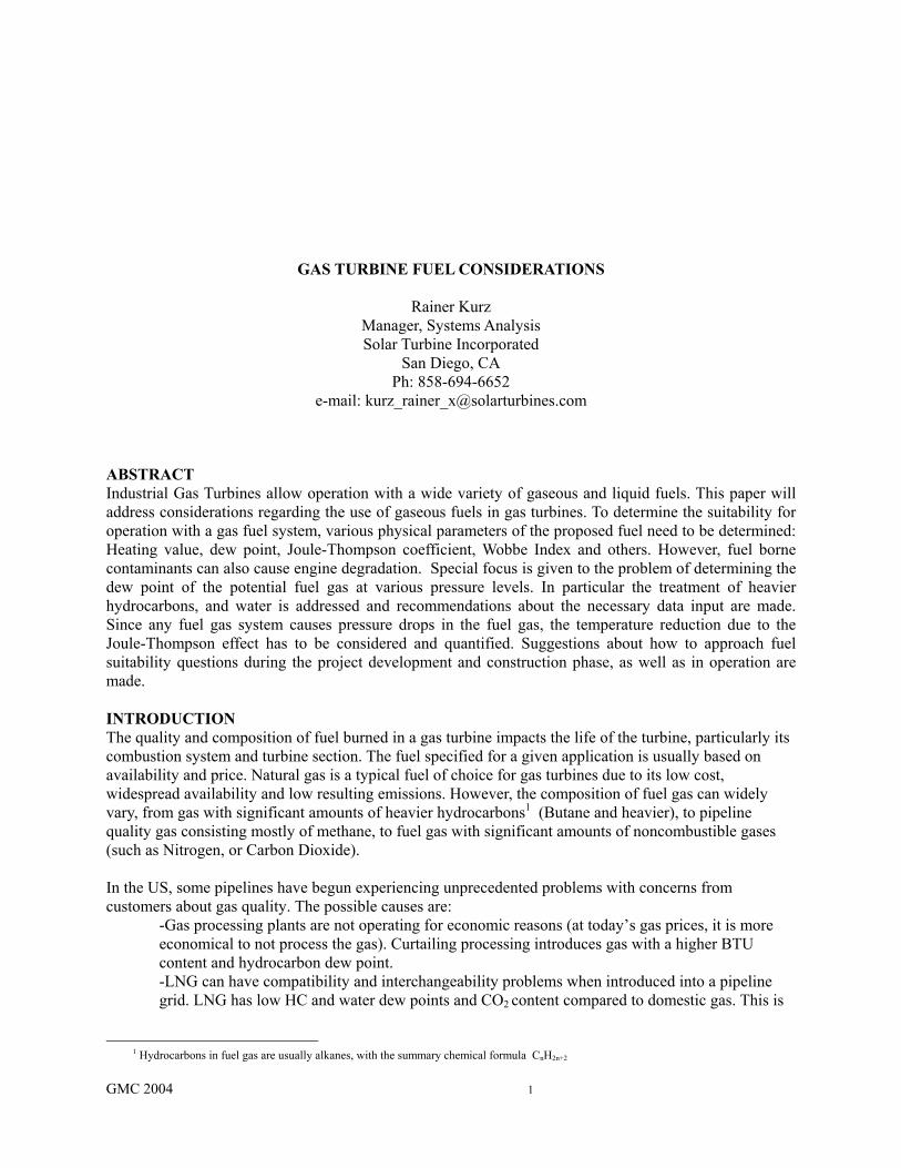
Figure 1: Typical Industrial Two Shaft Gas Turbine GAS TURBINES Gas Turbines are widely used in industrial applications. They usually are either single shaft or two shaft designs. Either design can use a standard, diffusion flame combustor, or a dry-low-emissions combustor (Greenwood, 2000). Most mechanical drive applications for gas turbines employ two-shaft gas turbines, while applications for power generation either employ single shaft or two shaft concepts. A two-shaft gas turbine (Figure 1) consists of an air compressor, a combustor, a gas generator turbine and a power turbine.2 The air compressor generates air at a high pressure, which is fed into to the combustor, where
2Some engines are configured as multi-spool engines. In this case, the gas generator has a low-pressure compressor driven by a
low-pressure turbine and a high-pressure compressor driven by a high-pressure turbine. For this configuration, the shaft connecting the LP compressor and turbine rotates inside the shaft connecting the HP compressor and turbine. In general, all the operating characteristics described above also apply to these engines.
GMC 2004 3
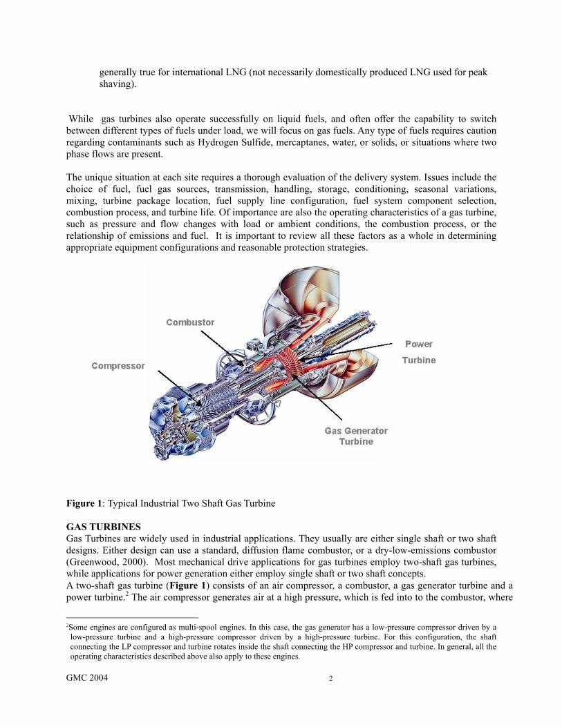
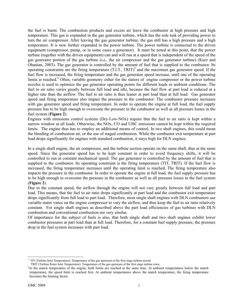
the fuel is burnt. The combustion products and excess air leave the combustor at high pressure and high temperature. This gas is expanded in the gas generator turbine, which has the sole task of providing power to turn the air compressor. After leaving the gas generator turbine, the gas still has a high pressure and a high temperature. It is now further expanded in the power turbine. The power turbine is connected to the driven equipment (compressor, pump, or in some cases a generator). It must be noted at this point, that the power turbine (together with the driven equipment) can and will run at a speed that is independent of the speed of the gas generator portion of the gas turbine (i.e., the air compressor and the gas generator turbine) (Kurz and Ohanian, 2003). The gas generator is controlled by the amount of fuel that is supplied to the combustor. Its operating constraints are the firing temperature (T.I.T., TRIT)3 and the maximum gas generator speed. If the fuel flow is increased, the firing temperature and the gas generator speed increase, until one of the operating limits is reached.4 Often, variable geometry either for the stators of engine compressor or the power turbine nozzles is used to optimize the gas generator operating points for different loads or ambient conditions. The fuel to air ratio varies greatly between full load and idle, because the fuel flow at part load is reduced at a higher rate than the airflow. The fuel to air ratio is thus leaner at part load than at full load. Gas generator speed and firing temperature also impact the pressure in the combustor: The combustor pressure increases with gas generator speed and firing temperature. In order to operate the engine at full load, the fuel supply pressure has to be high enough to overcome the pressure in the combustor as well as all pressure losses in the fuel system (Figure 2). Engines with emissions control systems (Dry-Low-NOx) require that the fuel to air ratio is kept within a narrow window at all loads. Otherwise, the NOx, CO and UHC emissions cannot be kept within the required limits. The engine thus has to employ an additional means of control. In two shaft engines, this could mean the bleeding of combustion air, or the use of staged combustion. While the combustor exit temperature at part load drops significantly for engines with standard combustion, it stays high for DLN engines. In a single shaft engine, the air compressor, and the turbine section operate on the same shaft, thus at the same speed. Since the generator speed has to be kept constant in order to avoid frequency shifts, it will be controlled to run at constant mechanical speed. The gas generator is controlled by the amount of fuel that is supplied to the combustor. Its operating constraint is the firing temperature (TIT, TRIT). If the fuel flow is increased, the firing temperature increases until the operating limit is reached. The firing temperature also impacts the pressure in the combustor. In order to operate the engine at full load, the fuel supply pressure has to be high enough to overcome the pressure in the combustor as well as all pressure losses in the fuel system (Figure 2). Due to the constant speed, the airflow through the engine will not vary greatly between full load and part load. This means, that the fuel to air ratio drops significantly at part load and the combustor exit temperature drops significantly from full load to part load. Therefore, most single shaft engines with DLN combustors use variable stator vanes on the engine compressor to vary the airflow, and thus keep the fuel to air ratio relatively constant. For single shaft engines as described above the part load efficiencies of gas turbines with DLN combustion and conventional combustion are very similar. Of importance for the subject of fuels is also, that both single shaft and two shaft engines exhibit lower combustor pressures at part load than at full load. Therefore, for a constant fuel supply pressure, the pressure drop in the fuel system increases with part load.
3 TIT (Turbine Inlet Temperature): Temperature of the gas upstream of the first stage turbine nozzle TRIT (Turbine Rotor Inlet Temperature): Temperature of the gas upstream of the first stage turbine rotor. 4At the match temperature of the engine, both limits are reached at the same time. At ambient temperatures below the match temperature, the speed limit is reached first. At ambient temperatures above the match temperature, the firing temperature becomes the limiting factor.
GMC 2004 4
60
80
100
120
140
160
180
200
220
260310 360 410460510560610660 710 760 810 Gas pressure psia
Gas
tem
p de
g F
Gas dew point 10 degF superheat gas 50 deg F superheat gas
Spec gas at req'd temp
Insurance Filter
Coalescer skid
Pressure regulator
Fuel control valve
Fuel manifold
A
D C
B
A
B
C D
Figure 2: Schematic of a Gas Fuel system, showing the pressure drop in various devices. If the gas is not superheated sufficiently, its temperature will eventually fall below the dew point temperature. Dry Low NOx (DLN) engines are a particular challenge regarding fuel quality. The general idea behind any DLN combustor currently in service is to generate a thoroughly mixed lean fuel and air mixture prior to entering the combustor of the gas turbine. The lean mixture is responsible for a low flame temperature, which in turn yields lower rates of NOx production. Because the mixture is very lean, in fact fairly close to the lean extinction limit, the fuel-to-air ratio has to be kept constant within fairly narrow limits. This is also necessary due to another constraint: The lower flame temperatures tend to lead to a higher amount of products related to incomplete combustion, such as CO and unburned hydrocarbons (UHC). The necessity to control the fuel-to-air ratio closely yields different part-load behavior when comparing gas turbines with conventional combustors and DLN engines.5 At certain levels of part load, the flame temperature is kept within limits by bleeding a certain amount of air from the compressor exit directly into the exhaust duct, or by fuel staging or by some form of variable geometry. Due to the requirement for thorough mixing prior to combustion, fuel channels for DLN systems tend to be narrower, and thus more susceptible to clogging due to solids in the fuel, than standard combustion systems. Also, a combustible mixture exists in the premixing portion of the injector. It must be avoided to ignite this mixture prior to its entering into the combustor. Therefore, autoignition behavior and flame speed of the fuel have to be carefully analyzed to avoid these problems.
5Regarding the requirements for DLN engines, multi-spool engines show no fundamental differences from single-spool engines.
GMC 2004 5
DLN systems for liquid fuel require fine atomization of the fuel with subsequent thorough mixing of fuel and air. Droplet sizes from given atomizers depend also on the physical properties (especially viscosity) of the liquid fuel. A limiting factor for lowering NOx emissions is often driven by the onset of combustor oscillations. Combustor oscillations are self-excited instabilities that gain their energy through positive feedback from the combustion process: A stable flame front would develop at some point in the combustion where the flow velocity reduces to the flame propagation velocity. Because Dry-Low-NOx systems require a lean fuel/air mixture, the velocity of propagation is significantly lower than for a normal diffusion combustion system; thus the position of the flame front is more easily influenced by slight flow disturbances. Assuming that fuel flow remains constant, a positive pressure pulse in the combustor causes a momentary decrease in the air entering the combustor. This creates a rich fuel pocket at the nozzles that travels downstream to the flame front. When this rich pocket reaches the flame after a certain delay, a sudden increase in heat release occurs which causes an increasing pressure. If the time delay of the rich fuel pocket traveling toward the flame front matches an acoustic period of the combustion chamber, then oscillations will occur. Changes in the fuel composition, causing variations in the combustion dynamics, can increase the oscillations in normally stable combustors, or borderline stable combustors. Some manufacturers recommend that a gas chromatograph or calorimeter be installed because of the sensitivity of DLE combustion to the fuel heating value if the heating may vary more than 2 to 3%. Other manufacturers allow changes in BTU content of 10%. A gas chromatograph is less expensive, but it updates only about every 5 or 6 minutes, whereas a calorimeter provides continuous reading of the Heating Value content. GAS FUELS Gas fuels for gas turbines are combustible gases, or mixtures of combustible and inert gases with a variety of compositions covering a wide range of heating values and densities. The combustible components can consist of methane and other low molecular weight hydrocarbons, hydrogen and carbon monoxide. The major inert components are nitrogen, carbon dioxide and water vapor. It is generally accepted that this type of fuel has to be completely gaseous at the entry to the fuel gas system, and at all points downstream to the fuel nozzle (ASME, 1992). Gaseous fuels can vary from poor quality wellhead gas to high quality consumer or “pipeline” gas. In many systems, the gas composition and quality may be subject to variations (Newbound et al, 2003). Typically, the major sources of contaminants within these fuels are:
• Solids
• Water
• Heavy gases present as liquids
• Oils typical of compressor oils
• Hydrogen sulfide (H2S)
• Hydrogen (H2)
• Carbon monoxide (CO)
• Carbon dioxide (CO2)
• Siloxanes
GMC 2004 6
Other factors that will affect turbine or combustion system life and performance include lower heating value (LHV), specific gravity (SG), fuel temperature, and ambient temperature. Some of these issues may co-exist and be interrelated. For instance, water, heavy gases present as liquids, and leakage of machinery lubricating oils, may be a problem for turbine operators at the end of a distribution or branch line, or at a low point in a fuel supply line.
Water in the gas may combine with other small molecules to produce a hydrate – a solid with an ice-like appearance. Hydrate production is influenced, in turn, by gas composition, gas temperature, gas pressure and pressure drops in the gas fuel system. Liquid water in the presence of H2S or CO2 will form acids that can attack fuel supply lines and components. Free water can also cause turbine flameouts or operating instability if ingested in the combustor or fuel control components. Heavy hydrocarbon gases present as liquids provide many times the heating value per unit volume than they would as a gas. Since turbine fuel systems meter the fuel based on the fuel being a gas, this creates a safety problem, especially during the engine start-up sequence when the supply line to the turbine still may be cold. Hydrocarbon liquids can cause:
-Turbine overfueling, which can cause an explosion or severe turbine damage). -Fuel control stability problems, because the system gain will vary as liquid slugs or droplets move through the control system. -Combustor hot streaks and subsequent engine hot section damage. -Overfueling the bottom section of the combustor when liquids gravitate towards the bottom of the manifold -Internal injector blockage over time, when trapped liquids pyrolyze in the hot gas passages.
Liquid carryover is a known cause for rapid degradation of the hot gas path components in a turbine (Anderson, 1980; Meher-Homji et al., 1998; Newbound et al, 2003 and 2004) . The condition of the combustor components also has a strong influence and fuel nozzles that have accumulated pipeline contaminants that block internal passageways will probably be more likely to miss desired performance or emission targets. Thus, it follows that more maintenance attention may be necessary to assure that combustion components are in premium condition. This may require that fuel nozzles be inspected and cleaned at more regular intervals or that improved fuel filtration components be installed. With a known gas composition, it is possible to predict dew point temperatures for water and hydrocarbons. However, the prediction methods for dew points may not always be accurate. In fact, it is known that different equations of state will yield different calculated dew points under otherwise identical conditions. Furthermore, the temperature in an unheated fuel line will drop, because the pressure drop due to valves and orifices in the fuel line causes a temperature drop in the gas (Figure 2). This effect is known as the Joule-Thompson effect. Most fuel gases (except hydrogen) will exhibit a reduction in temperature during an adiabatic throttling. Hydrogen on the other hand actually shows an increased temperature when the pressure drops, which is a potential explosion hazard.
GMC 2004 7
ProductionSeparator
Coalescer
PressureRegulator
Coalescer
Filter
Heater
LiquidDrop out
LiquidDrop out
Pressure feedback
Purchaserspecified gascomposition
above requiredtemperature
To engine
Purge/warm up
line
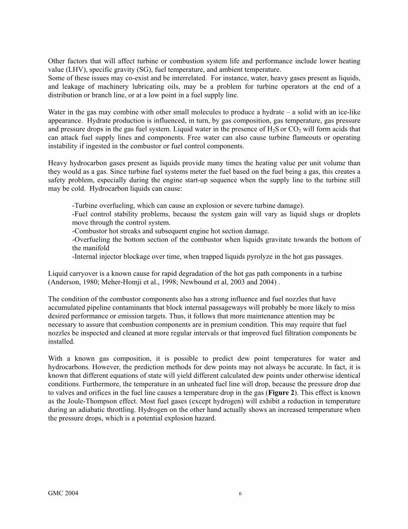
Figure 3: Schematic of Typical Oil or Gas Platform Fuel Conditioning System Protection against heavy gases and water present as liquids can be achieved by heating the fuel downstream of knockout drums and coalescing filters (Figure 3). The idea is to have a saturated gas at the exit of the knockout drum and filters and then to raise the temperature to the necessary superheat to prevent subsequent liquid dropout. The system shown in Figure 3 is typical for fuel systems on oil or gas platforms, where the gas produced is usually wet. For dry gas of well known composition, such as from gas plants or for pipeline applications, a less complex system may be appropriate (Figure 4).
Pipeline
Pressure
Regulator
Pressure feedback
Purchaser specified gas
composition above required
temperature
To engine
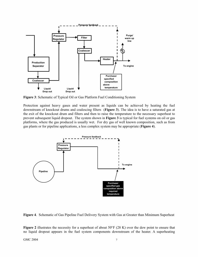
Figure 4. Schematic of Gas Pipeline Fuel Delivery System with Gas at Greater than Minimum Superheat Figure 2 illustrates the necessity for a superheat of about 50°F (28 K) over the dew point to ensure that no liquid dropout appears in the fuel system components downstream of the heater. A superheating
GMC 2004 8
requirement of 50°F (28 K) is currently acknowledged as an industry standard (ASME, 1992). The heat input yielded by a specific gas fuel is determined by the gas composition (including the moisture content), its mass flow, and its heating value. Performance representations for gas turbines are usually based on the lower heating value of the fuel gas, because the exhaust temperatures are always high enough to keep the water vapor in the exhaust from condensing. A gas analysis alone may not be entirely sufficient for the detection of heavy hydrocarbons, because it may only include the gases, but not the liquids in the stream. Also, it is common practice to lump all hydrocarbons from Hexane and heavier into one number. While this is perfectly acceptable for the calculation of the lower heating value as long as the Hexane and heavier hydrocarbons constitute a minute fraction of the gas, it will lead to a wrong estimate of the dew point. C14H30, even in parts-per-million amounts has a significant impact on the dew point of the gas mixture, as we will show later. Certainly a gas analysis has to be used in the project stage to allow for equipment sizing. Also, fuel systems usually limit the gas supply temperature due to temperature limits of its components. If the necessary superheat temperature exceeds the fuel system temperature limits, additional gas treatment may be necessary. Lower Heating Value, Specific Gravity, Fuel Temperature, and Ambient Temperature are important parameters since they influence the energy of the fuel flowing in the system. From the lower heating value (LHV) in Btu/scf [kJ/Nm3] and the specific gravity (SG), the Wobbe Index (WI) of the gas can be calculated:
SGLHVWI =
Because the fuel supply temperature Tf has an impact on the actual volumetric fuel flow, a temperature corrected Wobbe Index is often used, where the reference Temperature Tref is usually 520° R or 288K:
f
ref
TT
SGLHVWI ⋅=
If two different fuel gas compositions have the same Wobbe Index, the pressure drop in a given fuel system will be the same for both gases. The Wobbe Index is thus an indication of energy flow in the system at the same gas pressures and pressure drops. A standard fuel system may for example be designed for a Wobbe Index of 1220 ±10% Btu/scf (48,031 ±10% kJ/ Nm3) based on the LHV of the fuel. Different gas compositions can yield the same Wobbe Index, but they will have widely different hydrocarbon dew points. Minimum engine flameout fuel flows will also vary if the fuel contains high percentages of noncombustible gases. High fuel gas or ambient temperatures can cause problems if the temperature capabilities of elastomeric seals, electrical devices or other system components are exceeded. Low fuel gas or ambient temperatures can cause water or heavy hydrocarbon condensation. Protection against these factors includes analyzing the variations in the fuel composition, fuel temperature, and ambient temperature so that the required modifications to the fuel treatment system and turbine fuel system can be made. A turbine expected to operate with gaseous fuels exhibiting a wide Wobbe Index range will need to be configured differently than one that will only operate with a small
GMC 2004 9
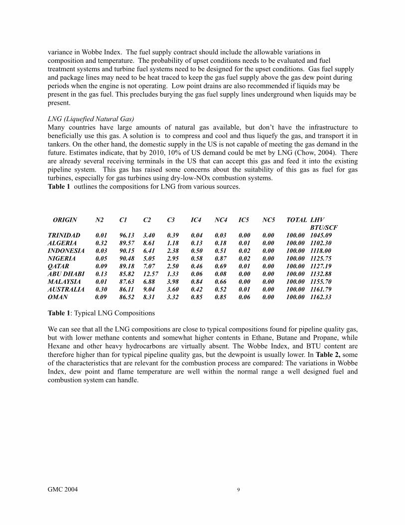
variance in Wobbe Index. The fuel supply contract should include the allowable variations in composition and temperature. The probability of upset conditions needs to be evaluated and fuel treatment systems and turbine fuel systems need to be designed for the upset conditions. Gas fuel supply and package lines may need to be heat traced to keep the gas fuel supply above the gas dew point during periods when the engine is not operating. Low point drains are also recommended if liquids may be present in the gas fuel. This precludes burying the gas fuel supply lines underground when liquids may be present. LNG (Liquefied Natural Gas) Many countries have large amounts of natural gas available, but don’t have the infrastructure to beneficially use this gas. A solution is to compress and cool and thus liquefy the gas, and transport it in tankers. On the other hand, the domestic supply in the US is not capable of meeting the gas demand in the future. Estimates indicate, that by 2010, 10% of US demand could be met by LNG (Chow, 2004). There are already several receiving terminals in the US that can accept this gas and feed it into the existing pipeline system. This gas has raised some concerns about the suitability of this gas as fuel for gas turbines, especially for gas turbines using dry-low-NOx combustion systems. Table 1 outlines the compositions for LNG from various sources. ORIGIN N2 C1 C2 C3 IC4 NC4 IC5 NC5 TOTAL LHV BTU/SCF TRINIDAD 0.01 96.13 3.40 0.39 0.04 0.03 0.00 0.00 100.00 1045.09 ALGERIA 0.32 89.57 8.61 1.18 0.13 0.18 0.01 0.00 100.00 1102.30 INDONESIA 0.03 90.15 6.41 2.38 0.50 0.51 0.02 0.00 100.00 1118.00 NIGERIA 0.05 90.48 5.05 2.95 0.58 0.87 0.02 0.00 100.00 1125.75 QATAR 0.09 89.18 7.07 2.50 0.46 0.69 0.01 0.00 100.00 1127.19 ABU DHABI 0.13 85.82 12.57 1.33 0.06 0.08 0.00 0.00 100.00 1132.88 MALAYSIA 0.01 87.63 6.88 3.98 0.84 0.66 0.00 0.00 100.00 1155.70 AUSTRALIA 0.30 86.11 9.04 3.60 0.42 0.52 0.01 0.00 100.00 1161.79 OMAN 0.09 86.52 8.31 3.32 0.85 0.85 0.06 0.00 100.00 1162.33 Table 1: Typical LNG Compositions We can see that all the LNG compositions are close to typical compositions found for pipeline quality gas, but with lower methane contents and somewhat higher contents in Ethane, Butane and Propane, while Hexane and other heavy hydrocarbons are virtually absent. The Wobbe Index, and BTU content are therefore higher than for typical pipeline quality gas, but the dewpoint is usually lower. In Table 2, some of the characteristics that are relevant for the combustion process are compared: The variations in Wobbe Index, dew point and flame temperature are well within the normal range a well designed fuel and combustion system can handle.
GMC 2004 10
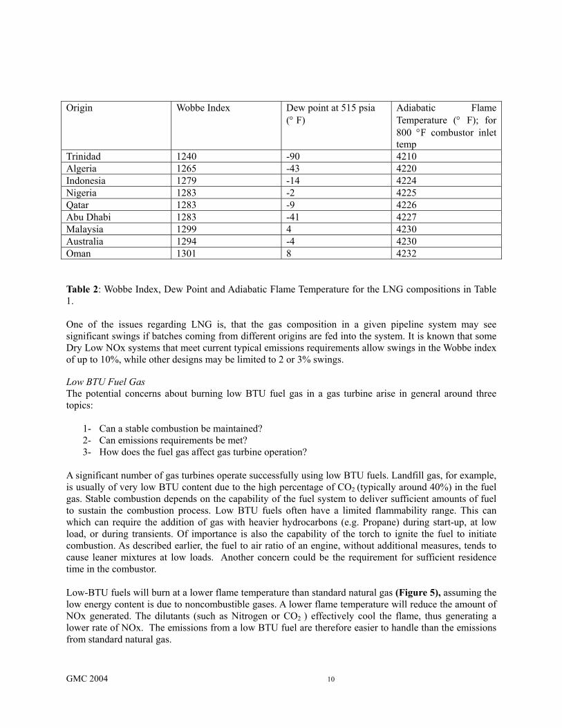
Origin Wobbe Index Dew point at 515 psia
(° F) Adiabatic Flame Temperature (° F); for 800 °F combustor inlet temp
Trinidad 1240 -90 4210 Algeria 1265 -43 4220 Indonesia 1279 -14 4224 Nigeria 1283 -2 4225 Qatar 1283 -9 4226 Abu Dhabi 1283 -41 4227 Malaysia 1299 4 4230 Australia 1294 -4 4230 Oman 1301 8 4232 Table 2: Wobbe Index, Dew Point and Adiabatic Flame Temperature for the LNG compositions in Table 1. One of the issues regarding LNG is, that the gas composition in a given pipeline system may see significant swings if batches coming from different origins are fed into the system. It is known that some Dry Low NOx systems that meet current typical emissions requirements allow swings in the Wobbe index of up to 10%, while other designs may be limited to 2 or 3% swings. Low BTU Fuel Gas The potential concerns about burning low BTU fuel gas in a gas turbine arise in general around three topics:
1- Can a stable combustion be maintained? 2- Can emissions requirements be met? 3- How does the fuel gas affect gas turbine operation?
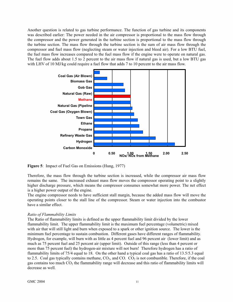
A significant number of gas turbines operate successfully using low BTU fuels. Landfill gas, for example, is usually of very low BTU content due to the high percentage of CO2 (typically around 40%) in the fuel gas. Stable combustion depends on the capability of the fuel system to deliver sufficient amounts of fuel to sustain the combustion process. Low BTU fuels often have a limited flammability range. This can which can require the addition of gas with heavier hydrocarbons (e.g. Propane) during start-up, at low load, or during transients. Of importance is also the capability of the torch to ignite the fuel to initiate combustion. As described earlier, the fuel to air ratio of an engine, without additional measures, tends to cause leaner mixtures at low loads. Another concern could be the requirement for sufficient residence time in the combustor. Low-BTU fuels will burn at a lower flame temperature than standard natural gas (Figure 5), assuming the low energy content is due to noncombustible gases. A lower flame temperature will reduce the amount of NOx generated. The dilutants (such as Nitrogen or CO2 ) effectively cool the flame, thus generating a lower rate of NOx. The emissions from a low BTU fuel are therefore easier to handle than the emissions from standard natural gas.
GMC 2004 11
Another question is related to gas turbine performance. The function of gas turbine and its components was described earlier: The power needed in the air compressor is proportional to the mass flow through the compressor and the power generated in the turbine section is proportional to the mass flow through the turbine section. The mass flow through the turbine section is the sum of air mass flow through the compressor and fuel mass flow (neglecting steam or water injection and bleed air). For a low BTU fuel, the fuel mass flow increases compared to the fuel mass flow if the engine were to operate on natural gas. The fuel flow adds about 1.5 to 2 percent to the air mass flow if natural gas is used, but a low BTU gas with LHV of 10 MJ/kg could require a fuel flow that adds 7 to 10 percent to the air mass flow. Figure 5: Impact of Fuel Gas on Emissions (Hung, 1977) Therefore, the mass flow through the turbine section is increased, while the compressor air mass flow remains the same. The increased exhaust mass flow moves the compressor operating point to a slightly higher discharge pressure, which means the compressor consumes somewhat more power. The net effect is a higher power output of the engine. The engine compressor needs to have sufficient stall margin, because the added mass flow will move the operating points closer to the stall line of the compressor. Steam or water injection into the combustor have a similar effect. Ratio of Flammability Limits The Ratio of flammability limits is defined as the upper flammability limit divided by the lower flammability limit. The upper flammability limit is the maximum fuel percentage (volumetric) mixed with air that will still light and burn when exposed to a spark or other ignition source. The lower is the minimum fuel percentage to sustain combustion. Different gases have different ranges of flammability. Hydrogen, for example, will burn with as little as 4 percent fuel and 96 percent air (lower limit) and as much as 75 percent fuel and 25 percent air (upper limit). Outside of this range (less than 4 percent or more than 75 percent fuel) the hydrogen-air mixture will not burn! Therefore hydrogen has a ratio of flammability limits of 75/4 equal to 18. On the other hand a typical coal gas has a ratio of 13.5/5.3 equal to 2.5. Coal gas typically contains methane, CO2, and CO. CO2 is not combustible. Therefore, if the coal gas contains too much CO2 the flammability range will decrease and this ratio of flammability limits will decrease as well.
Coal Gas (Air Blown)Biomass Gas
Gob Gas
Natural Gas (Raw)
Methane
Natural Gas (Pipeline
Coal Gas (Oxygen Blown)
Town GasEthane
Propane
Refinery Waste Gas
Hydrogen
Carbon Monoxide0 0.50 1.00 1.50 2.00 2.50
NOx/ NOx from Methane
GMC 2004 12
So how does this relate to operation of a gas turbine? In the combustor, the fuel and air must be continually burned to keep the engine running. When the flame in the combustor is extinguished it is called a flame-out or blow-out. The fuel to air ratio changes with the engine load, as described earlier. In order to prevent flame-out the combustor must support combustion over a range of fuel to air ratios. As explained above each fuel composition has its own flammability range (Ratio of Flammability Limits). If the engine required fuel to air ratio range is equal to or larger than the fuel flammability range than at some point the engine will experience flameout and will not be able to operate at that point. Knowing the ratio of flammability limits allows a decision whether the fuel composition has a broad enough flammability range to support combustion for all operating points of the engine. Stoichiometric Flame Temperature The stoichiometric flame temperature impacts the amount of NOx emissions. It is also a parameter to help verify that a given fuel composition can be burned at all gas turbine operating loads and idle. Across the flammability range the mixtures of fuel and air will burn at different temperatures. As the fuel to air ratio is increased from the lower flammability limit, the flame temperature will increase. Upon further increase in the ratio a point will be reached where the amount of fuel and air will be perfectly matched so that all the oxygen in the air is reacted with all the fuel - this is called the stoichiometric fuel to air ratio. It also corresponds to the maximum flame temperature. As the fuel to air ratio is increased further still the flame temperature starts to decrease and continues to decrease until the upper flammability limit is reached. In standard combustion systems, with a very heterogeneous mixture, the flame temperature is close to the stoichiometric flame temperature. The flame temperature has a significant impact on the NOx production rate (Greenwood, 2000) . Auto ignition Auto ignition is a process where a combustible mixture spontaneously reacts and releases heat in absence of any concentrated source of ignition such as a spark or a flame (Lefebvre, 1998). In lean premix combustors, or in general, in any combustor where fuel and air are premixed prior to combustion, this spontaneous ignition has to be avoided, because it can damage combustor components, and yields high pollutant emissions. The auto ignition delay time of a fuel is the time between the creation of a combustible mixture and the onset of the flame. This parameter is a function of the fuel composition, the fuel to air ratio, the pressure, and the mixture temperature. Leaner mixtures tend to have a longer delay time, while higher mixture temperatures and higher pressures tend to shorten the delay time. In a lean premix injector, the flow velocities thus have to be high enough to avoid auto ignition inside the injector at the prevailing temperatures. Increasing the content of heavier hydrocarbons in an associated gas leads to a decrease of delay time. This is mainly caused by the non-symmetry of all higher hydrocarbons: Heavy hydrocarbons can be attacked much easier than methane molecules, resulting in reduced ignition delay times. Flashback Flame speed is a propagation of the flame front moving in the combustion zone. Changes in the fuel composition, fuel to air ratio and inlet temperature affect the flame speed (Glassman, 1996). Flame propagation velocity is strongly influenced by the fuel/air mixture ratio; the leaner the mixture the lower the velocity. If the flow velocity exceeds the flame propagation velocity, then flameout could occur. If the flame propagation velocity exceeds the flow velocity, then flashback within the premixing injectors could occur that can cause damage by overheating the injector tips and walls. To maintain flame stability at a point, the velocity of the fuel-air mixture must be within the flame-propagation speed to prevent flashback (Lefebvre,1998). Flame flashback from the combustion chamber into the premixing zone is one of the inherent reliability problems of lean premixed combustion. The flame speed is one of the most
GMC 2004 13
important parameters governing flashback. High flame speeds occur for example in associated gases containing high percentages of propane or butane. Dew point For fuel gas containing heavier hydrocarbons or water, the temperature of the gas has to be high enough to avoid the dropping out of liquids. The dew point temperature of a gas is the temperature at a given pressure at which the first drop of liquid forms in equilibrium with the gas. When a real gas experiences a drop in pressure (e.g. due to a flow orifice or a valve), and no heat or work is exchanged with the environment, the temperature of the gas will change. The enthalpy of the gas stays constant. This behavior is called Joule-Thompson Effect. The temperature will actually drop for most gases (in particular hydrocarbons) except hydrogen when the pressure is reduced. Since any fuel system will cause a pressure drop to the fuel , fuel gas that is above the dew point at the fuel system inlet, could experience liquid drop out due to this drop in temperature. The situation is often aggravated by heat loss of the fuel system when the surrounding temperature is lower than the fuel supply temperature. Because the calculation of the dew point temperature, the enthalpy at the dew point, and the enthalpy of the gas mixture at various pressures is so important, we will discuss it in more detail. The necessary calculations are performed using a suitable equation of state (examples are Soave-Redlich-Kwong, Redlich-Kwong (Poling et al, 2001), Peng-Robinson (1976), to name a few). These semi-empirical correlations allow, for a known gas composition, to calculate the dew point temperature and dew point enthalpy for a given pressure. They also allow to calculate the enthalpy of the gas for given pressures and temperatures. Thus, as long as the enthalpy of the gas is higher than the enthalpy at the dew point (for a given pressure), no liquid dropout will occur. The basis for performing a dew point calculation is the understanding that it is an equilibrium state. The fundamental thermodynamic relation for phase equilibria, such as the dew point, is that the fugacity of each component in the vapor phase is equal to the fugacity of the same component in the liquid phase. This arises because the fugacity is a measure of the "escaping tendency" for a component to leave its phase. Thus, when a component's fugacity is the same in two or more homogeneous phases in contact, there will be no net mass transfer, i.e., equilibrium exists. The fugacity coefficient is calculated using an equation of state. Elliott at al. (2002) describe the calculation procedure in detail. If water is present in the gas, then the problem becomes more complex. Though the systems of interest are mostly alkanes and, in some cases, non-polar inorganic gases, an aqueous phase may be formed at a higher temperature than the organic phase. The dew point calculated is not necessarily the relevant one, since it is possible for the organic phase to drop out first. The preferred method is to calculate both the dew point where the organic phase drops out first and the dew point where the aqueous phase drops out first, and then to choose whichever temperature is larger.
GMC 2004 14
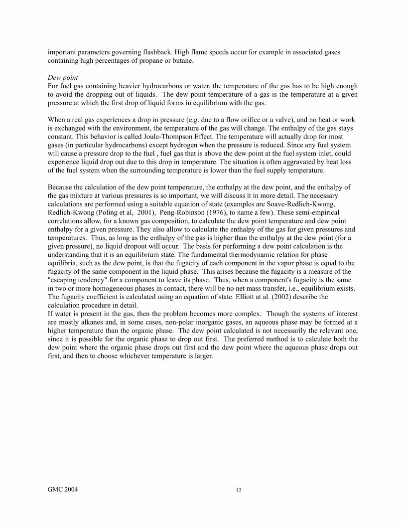
Figure 6: Dew line for different gas mixtures in a pressure(bar)-temperature(K) diagram. Gas composition is: Methane 73.8%,Ethane 8.2%,Propane 3.23%, I-Butane .28%, n-Butane 0.78%, I-Pentane 0.24%,n-Pentane 0.18%, n-Hexane 0.18%, Cxx 0.71%, Nitrogen 0.93%, Carbondioxide 11.68%. Cxx represents either Hexane (C6), Octane(C8) or Decane(C10). Despite the fact that Cxx represents only 0.71% of the gas, it has a significant impact on the dew point. To conduct a successful determination of the fuel system capability, the fuel gas composition, possible contaminants, the fuel supply pressure and temperature need to be known. As part of this study, it became obvious that the dew point of a hydrocarbon gas mixture is highly dependent on the heavier hydrocarbons. The common practice to report Hydrocarbons individually only up to pentane, and lump all heavier hydrocarbons into one C6+ number may yield sufficient information about the lower heating value and the Wobbe Index of the fuel. It will not yield an accurate dew point, however. In Figure 6, a typical situation is evaluated: A fuel gas composition has 0.71 percent of its constituents lumped together as C6+. Then, dew points are calculated assuming these constituents are either all Hexane, or all Octane or all Undecane. As Figure 6 shows, even small amounts of heavier hydrocarbons have a significant effect on the dew point of the gas mixture. Campbell (1998) suggests therefore to determine the individual constituents of the gas composition up to C14. Arguably, the practice to remove all liquids in a separator, and then to heat the gas portion by, say 50°F (28 K), will insure that the gas supplied to the gas turbine will indeed be superheated by 50°F (28K). However, a proper sizing of the heater is not possible without knowing (at least approximately), the required end temperature. Also, fuel system components usually have maximum allowable temperatures. Without prior knowledge of the necessary gas temperature, the fuel system temperature limits may not allow the necessary superheat. It must be noted that all the prior statements assume an adiabatic fuel system. Heat loss in the fuel system will occur, however, if the system is not insulated and the surrounding temperature is significantly lower than the fuel supply temperature. In particular during start-up at low ambient temperatures, when the fuel system is still cold liquids can form. A system without heat tracing needs to be evaluated assuming the lowest surrounding temperature. However, standard heat transfer methods allow to approximate the heat
200
220
240
260
280
300
320
340
360
380
400
0 10 20 30 40 50 60 70 80 90 100
pressure
tem
p
C6
C10
C8

GMC 2004 15
loss of a fuel system under arbitrary surrounding conditions, and using the first law of thermodynamics, to calculate the fuel gas enthalpy at any point of the fuel system. As described above, this enthalpy has to be higher than the enthalpy of the vapor at the dew point. Avoidance of Liquid Dropout Many gas turbine installations operate with very simple fuel supply systems, especially if the fuel composition and supply temperature and pressure are constant. If the fuel analysis determines that there will not be any liquid dropout under any operating condition with sufficient superheat margin, the system as outlined in Figure 4 should be sufficient. In applications where the fuel quality is subject to significant change, or where a sufficient margin of superheat cannot be ensured, a fuel system as outlined in Figure 3 is more appropriate. In such a fuel system with a separator and subsequent heater, the fuel will leave the separator in a saturated state (either saturated with water or heavy hydrocarbons). The temperature increase in the heater is thus equal to the amount of superheat of the gas. On a side note, for a given required amount of superheating, the required heat input of the heater PH is approximately:
TcWP pH ∆⋅⋅=
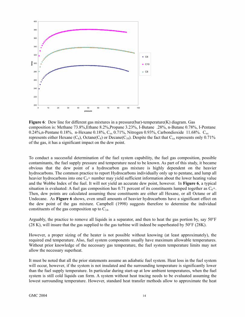
The heater can be electric, or use hot water; exhaust heat can also be used to heat fuel, using heat exchangers.To determine whether the system will be capable of avoiding liquid drop out, the enthalpy of the fuel gas has to be calculated at the skid edge. Knowing the gas composition, the gas pressure and the gas temperature at skid edge allows calculating the enthalpy of the gas. The pressure in the combustor depends on the engine load (Figure 7). The exact slope of combustor pressure versus load depends on the design of the engine; in particular whether it is a single or two-shaft engine, and the type of engine controls used. We further assume that the velocities in the fuel system stay low (i.e. there is no significant difference between the static and the total enthalpy). The necessary condition to avoid liquid drop out in an adiabatic fuel system is, that for all pressure levels that may occur in this fuel system, the enthalpy of the vapor at the dew point is lower than the enthalpy of the gas at the skid edge (Figure 7)6. This approach does obviously not account for the effect of high velocities in the fuel system, as they can occur in partially closed valves. These high velocities can lead to a significant drop in the enthalpy, and can easily cause a situation where liquids drop out. However, this situation is not as critical as it looks at the first glance. First, the velocities will drop again after the valve. The static enthalpy will therefore increase, so even if droplets may have formed, they will evaporate again. Second, it is known (Gyarmathy, 1962) that in situations with rapidly accelerated gas there is a time lag between the condition where the state of the gas would indicate liquid droplets and the actual formation of droplets. This effect is frequently experienced in steam turbines, where, during the rapid acceleration of the steam in the nozzles, steam can be substantially supercooled without forming liquids. Under quasi -stationary conditions, we can easily describe the change of states from skid edge to the exit of the fuel injector into the combustor. The conditions at skid edge are known, and the engine compressor exit pressure or the actual combustor pressure can be used to approximate the pressure at the injector exit. The path in a Mollier diagram is shown in Figure 7. The dew line, which is typical for hydrocarbon fuel gas, shows a distinct maximum δH/δp =0. The shape of the dew line thus suggests, that the highest chance of liquid dropout occurs not necessarily at the lowest pressure in the combustor. The example in
6 The Joule Thompson Effect manifests itself in the fact, that for the condition of a pressure drop at constant enthalpy, the temperature of the
gas will change. For an ideal gas in the same situation, temperature and enthalpy would remain constant.
GMC 2004 16
0
0.2
0.4
0.6
0.8
1
1.2
0 0.2 0.4 0.6 0.8 1 1.2
Load (%)
Com
bust
or P
ress
ure
PCD-2shaftPCD-1shaft
Figure 7: Engine compressor discharge pressure (pcd) as a function of engine load, and the resulting process path of fuel gas in an adiabatic fuel system.
Appendix A outlines a situation, where the liquid dropout would become likely at part load operation of the engine. In evaluating these fuel systems, one must take into account that the highest pressure drops in the fuel system may not occur at full load, but rather during the starting of the engine, when the combustor pressure is lowest (Figure 7). In other words, the system has to be evaluated for the highest pressure that the gas can have at skid edge, and the combustor pressure at light-off conditions, as well as for any load condition between idle and full load. Additionally, unless the fuel lines are heat traced, they may be colder than the fuel especially during start up. Therefore, a significant safety margin between the dew point temperature, and the lowest possible fuel temperature is necessary.
GMC 2004 17
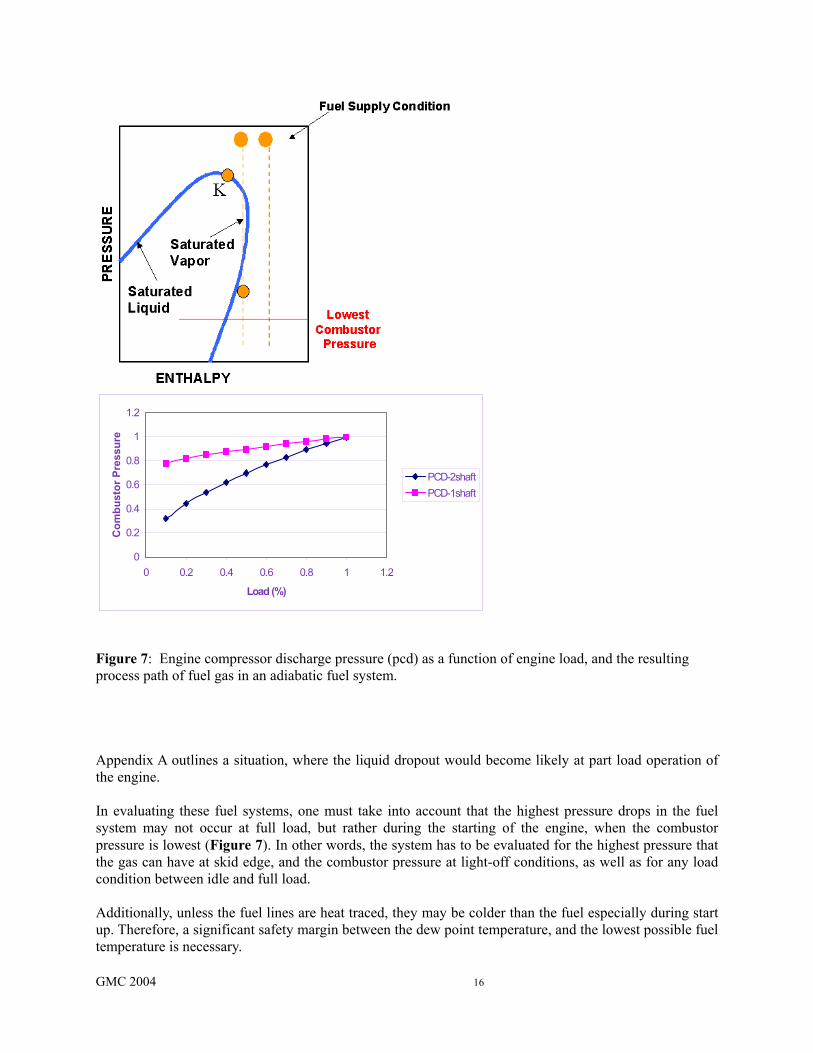
Dew Point Monitoring Newbound and Wagiella (2003) presented data from online dew point monitoring systems. They state that many operators of gas turbines lack sufficient data about the dew point of the fuel gas they use for their turbines to determine the safe fuel inlet temperature threshold. Their data indicates significant changes in the dew point of their fuel gas over time, with daily variations of 12° -14°F (7°-8°C). Figure 8 shows an example of these variation of dew points. Since the fuel supply temperature drops below the dewpoint, formation of liquids is inevitable.
Figure 8: Variations in Dew point and Fuel Inlet Temperature at a Gas turbine Installation (Newbound et al, 2004). The reasons for these fluctuations are given as a result of the warming and cooling down of the pipeline with daily temperature changes, and subsequent accumulation of heavy hydrocarbons. Other reasons include process changes in upstream gas plants, or a change of supply wells (especially for applications close to gas fields). In cases where these fluctuations are present, and a reason for concern, automated dew point monitors are recommended, because on-line gas chromatography is usually not set up to analyze hydrocarbons up to C14. When liquids are generated, they often occur in slugs rather than fine mist. In many systems, they accumulate at the low points, and eventually get carried away by the gas flow. This means that in the combustor locally very high temperatures are generated, which create streaks of hot gas that can quickly overheat exposed sections of the turbine or the combustor liner. Hydrogen Sulfide Hydrogen sulfide (H2S) causes a number of challenges to the operation of a gas turbine. The fact that it is highly toxic requires sufficient protection of personnel from leakages. Hydrogen sulfide and CO2 form acids in the presence of liquid water. Since many fuels are water saturated, sufficient superheat over the water dew point of the fuel as well as heat tracing has to be provided, to avoid corrosion of the fuel system. The Sulfur contained in Hydrogen Sulfide (as well as in Mercaptanes) will react in the combustion process to from SO2 and SO3. These gases are often regulated because they can cause acid rain. Additionally, if sulfur has the opportunity to react with sodium or potassium (which often is introduced with the combustion air, especially in offshore applications) in the combustor, it will form alkali sulfates that can cause hot corrosion in the hot section of the gas turbine (Meher-Homjii et al., 1998). It is
GMC 2004 18
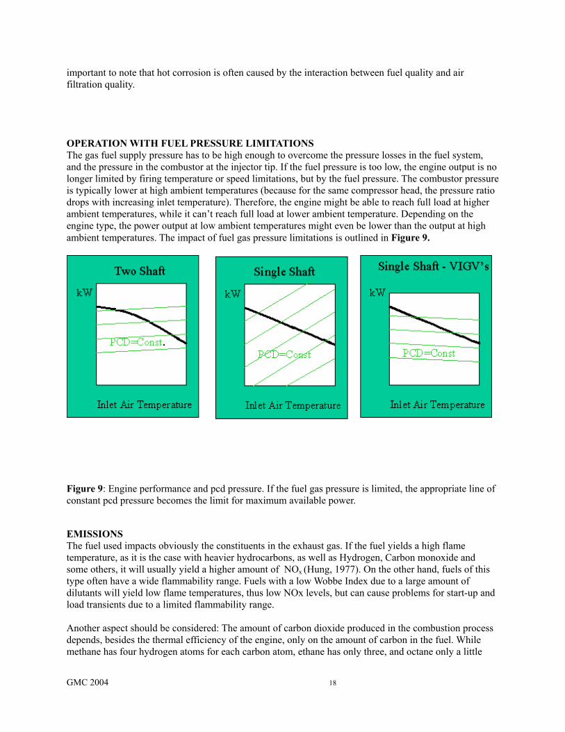
important to note that hot corrosion is often caused by the interaction between fuel quality and air filtration quality. OPERATION WITH FUEL PRESSURE LIMITATIONS The gas fuel supply pressure has to be high enough to overcome the pressure losses in the fuel system, and the pressure in the combustor at the injector tip. If the fuel pressure is too low, the engine output is no longer limited by firing temperature or speed limitations, but by the fuel pressure. The combustor pressure is typically lower at high ambient temperatures (because for the same compressor head, the pressure ratio drops with increasing inlet temperature). Therefore, the engine might be able to reach full load at higher ambient temperatures, while it can’t reach full load at lower ambient temperature. Depending on the engine type, the power output at low ambient temperatures might even be lower than the output at high ambient temperatures. The impact of fuel gas pressure limitations is outlined in Figure 9.
Figure 9: Engine performance and pcd pressure. If the fuel gas pressure is limited, the appropriate line of constant pcd pressure becomes the limit for maximum available power. EMISSIONS The fuel used impacts obviously the constituents in the exhaust gas. If the fuel yields a high flame temperature, as it is the case with heavier hydrocarbons, as well as Hydrogen, Carbon monoxide and some others, it will usually yield a higher amount of NOx (Hung, 1977). On the other hand, fuels of this type often have a wide flammability range. Fuels with a low Wobbe Index due to a large amount of dilutants will yield low flame temperatures, thus low NOx levels, but can cause problems for start-up and load transients due to a limited flammability range. Another aspect should be considered: The amount of carbon dioxide produced in the combustion process depends, besides the thermal efficiency of the engine, only on the amount of carbon in the fuel. While methane has four hydrogen atoms for each carbon atom, ethane has only three, and octane only a little
GMC 2004 19
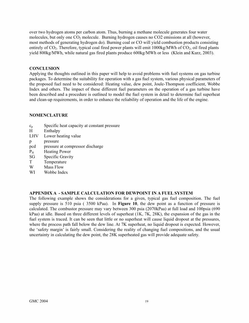
over two hydrogen atoms per carbon atom. Thus, burning a methane molecule generates four water molecules, but only one CO2 molecule. Burning hydrogen causes no CO2 emissions at all (however, most methods of generating hydrogen do). Burning coal or CO will yield combustion products consisting entirely of CO2. Therefore, typical coal fired power plants will emit 1000kg/MWh of CO2, oil fired plants yield 800kg/MWh, while natural gas fired plants produce 600kg/MWh or less (Klein and Kurz, 2003). CONCLUSION Applying the thoughts outlined in this paper will help to avoid problems with fuel systems on gas turbine packages. To determine the suitability for operation with a gas fuel system, various physical parameters of the proposed fuel need to be considered: Heating value, dew point, Joule-Thompson coefficient, Wobbe Index and others. The impact of these different fuel parameters on the operation of a gas turbine have been described and a procedure is outlined to model the fuel system in detail to determine fuel superheat and clean-up requirements, in order to enhance the reliability of operation and the life of the engine. NOMENCLATURE cp Specific heat capacity at constant pressure H Enthalpy LHV Lower heating value p pressure pcd pressure at compressor discharge PH Heating Power SG Specific Gravity T Temperature W Mass Flow WI Wobbe Index APPENDIX A - SAMPLE CALCULATION FOR DEWPOINT IN A FUEL SYSTEM The following example shows the considerations for a given, typical gas fuel composition. The fuel supply pressure is 510 psia ( 3500 kPaa). In Figure 10, the dew point as a function of pressure is calculated. The combustor pressure may vary between 300 psia (2070kPaa) at full load and 100psia (690 kPaa) at idle. Based on three different levels of superheat (1K, 7K, 28K), the expansion of the gas in the fuel system is traced. It can be seen that little or no superheat will cause liquid dropout at the pressures, where the process path fall below the dew line. At 7K superheat, no liquid dropout is expected. However, the ‘safety margin’ is fairly small. Considering the reality of changing fuel compositions, and the usual uncertainty in calculating the dew point, the 28K superheated gas will provide adequate safety.
GMC 2004 20
Figure 10: Dew point Enthalpy for gas fuel and process path for adiabatic expansion starting with different degrees of superheat. Fuel gas composition is: Methane 83%,Ethane 8%,Propane3%, I-Butane 0.3%, n-Butane 0.8%, I-Pentane 0.3%, n-Pentane 0.3%,n-Hexane 0.4%, n-Heptane 0.2%, n-Octane 0.08%, n-Nonane 0.02%, n-Decane 0.01%, Nitrogen 1.9%, Carbondioxide 1.69%. REFERENCES Anderson, A.W., 1980, Sawyers Turbomachinery Maintenance Handbook, Vol.1, Turbomachinery Intl Publications, Norwalk,CT. ASME B133.7,1992, ”Gas Turbine Fuels” Campbell,J.M., 1998, Gas Conditioning and Processing Chow, K., 2004, ‘LNG Role in Gas Supply/Demand’, Gas Electric Partnership, VII Workshop, Houston, Tx Elliott, F.G., Kurz, R., Etheridge, C., and O’Connell, J.P., 2004, “Fuel System Suitability Considerations for Industrial Gas Turbines’ , TransASME J Eng for Gas Turbines and Power, Vol. 126, pp119-126. Glassman,I, 1996, Combustion, Academic Press, New York, 3rd Edition. Greenwood, S.A, 2000, ”Low Emission Combustion Technology for Stationary Gas Turbine Engines”, Proc.29th Turbomachinery Symposium, Houston, Tx Gyarmarthy, G., 1962, “Grundlagen einer Theorie der Nassdampfturbine”, Diss. ETH Zuerich
4.6
4.7
4.8
4.9
5
5.1
5.2
5.3
5.4
5.5
5.6
0 1000 2000 3000 4000
pressure -kPa
enth
alpy
-kJ/
mol
e
dewpoint enthalpy1K Superheat7K Superheat28K Superheat
GMC 2004 21
Hung, W.S.Y., 1977, “The NOx Emission Levels of Unconventional Fuels for Gas Turbines”, ASME Paper 77-GT-16 . Klein, M., Kurz, R., 2003, ‘An Output Based Approach to Emissions Standards for Industrial Gas turbines’, ASME GT2003-38785. Kurz, R., Ohanian, S., 2003,’Modelling Turbomachinery in Pipeline Simulations’, Proc. PSIG 03, Berne, Switzerland Lefebvre,A.H., 1998, Gas Turbine Combustion, 2nd Ed., Taylor and Francis, Philadelphia Meher-Homji,C.B., Gabriles, G. A., 1998, ‘Gas Turbine Blade Failures-Causes, Avoidance and Troubleshooting’, Proc. 27th Texas A&M Turbomachinery Symposium Newbound, T.D., Wagiealla, W.,2003, ‘On-Line Hydrocarbon Dew Point Monitoring in Fuel Gas’, ASME GT2003-38868 Newbound, T.D., Al-Showiman,K.S., 2004, ‘Tuning Your Fuel-Gas Delivery System’, ASME GT2004-53298. Peng, D.Y., and Robinson, D.B., 1976, “A New Two-Constant Equation of State,” Ind. Eng. Chem. Fundam., Vol. 15, pp. 59-64. Poling, B.E., Prausnitz, J.M., O'Connell, J.P.,2001, The Properties of Gases and Liquids, 5th ed. McGraw-Hill, New York


![Dual Fuel Gas Turbine[1]](https://static.fdocuments.in/doc/165x107/551502d84a7959d2028b511e/dual-fuel-gas-turbine1.jpg)