
Gas Transmission R&D Programme Detailed Reports · Effect of Post Weld Heat Treatment (PWHT) on...
109
313 Annual Report 2011/12 Innovation Funding Incentive Gas Transmission R&D Programme Detailed Reports
Transcript of Gas Transmission R&D Programme Detailed Reports · Effect of Post Weld Heat Treatment (PWHT) on...
313
Annual Report 2011/12
Innovation Funding Incentive
Gas Transmission R&D Programme Detailed Reports

314
Gas Transmission R&D Programme Detailed Report
During the financial year 2011/2012 National Grid Gas Transmission utilised 98.0% of the Innovation Funding Incentive across a number of programme areas. The programme areas have been reclassified to match National Grids Innovation submission for RIIO and the associated projects are indexed below with a detailed progress reports.
Contents
Safety ..........................................................................................................315 Safe Working Practices...................................................................................................... 315
Risk Assessment Methodologies for Pipelines and AGIs .............................................. 315 Modernisation of Fire & Gas Protection Strategy........................................................... 318
Infrastructure ...................................................................................................................... 322 Detection & Management of Corrosion on Above Ground Insulated Pipework and Pipe Supports ......................................................................................................................... 322 Optimisation of Integrity Management at Sleeved Crossings ........................................ 324 Development of AC Over Line Survey System .............................................................. 326 Magnetic Tomography Method (MTM) Pipeline Inspection System: Evaluation & Validation........................................................................................................................ 332 Ledeen Valve Actuator Tie Rod Condition ..................................................................... 337 Pit Wall Transitions (PWT) Inspection Technologies ..................................................... 341 Effect of Post Weld Heat Treatment (PWHT) on Thermo-Mechanically Controlled Process (TMCP) Steel Pipelines.................................................................................... 344 Ageing Critical Valve Research...................................................................................... 347 The Need for Pressure De-rating Prior To In-Service Welding...................................... 349 Dev. of Novel Mitigation Methods for High Frequency Main Pipework Vibration........... 352
Third Party Interference ..................................................................................................... 354 Installation of IRIS separators ........................................................................................ 354 Third Party Work Surveillance........................................................................................ 356
Reliability....................................................................................................359 Optimising Asset Management .......................................................................................... 359
Pipeline Impact Detection System ................................................................................. 359 AGI Paint Systems ......................................................................................................... 361 High Pressure Metering Uncertainty Calculation Tool ................................................... 365 Efficacy of Low Flow Differential Pressure Measurement for Orifice Plate Meters........ 368 Evaluation of Chemical Rock Breaking .......................................................................... 376
Gas Quality ........................................................................................................................ 379 External Contamination Detection and Measurement at Entry Points ........................... 379 Development of FWACV Capability for New Gas Chromatograph DANINT Software .. 383
Capacity & Capability ......................................................................................................... 386 Combined Geophysics Tool for Pipelines Routeing & Risk Assessment ...................... 386
Environment ...............................................................................................388 Operational Venting ........................................................................................................... 388
Alternatives to Venting from the NTS Gas Transmission System.................................. 388 Environmental Study for Future Above Ground Facility Developments......................... 392 Bleed Reduction on Gas Chromatographs .................................................................... 397
Customer Satisfaction & Commercial......................................................399 Charging Frameworks........................................................................................................ 399
Daily Gas Demand Forecasting ..................................................................................... 399 Information Provision ......................................................................................................... 401
Automatic Risk-Based Handling Of Plant Enquiries ...................................................... 401
Strategic .....................................................................................................403 New Material & Technology ............................................................................................... 403
Research into Requirements for Gaseous Phase CO2 Transmission ........................... 403 Feasibility study into the use of composite materials as impact protection for road crossings ........................................................................................................................ 414 Leveraged International Research Programmes for Gas Pipelines and Above Ground Facilities.......................................................................................................................... 417

315
Safety
Safe Working Practices
Project title Risk Assessment Methodologies for Pipelines and AGIs
Project Engineer
Dave McCollum
Description of project
Research into the ongoing improvement of risk management software and associated databases for the management of safety risks on gas transmission pipelines. Development of models and procedures through the joint venture, PIPESAFE Group, and other collaborations.
Research into the management of safety risks on above ground installations. Development of models and procedures through the joint venture ORDER collaboration.
Expenditure for financial year
Internal £13k
External £103k
Total £117k
Expenditure in previous (IFI) financial years
Internal £12k
External £59k
Total £71k
Total project costs (collaborative + external + NG)
£246k Projected 2011/12 costs for NG
£58k
Technological area and/or issue addressed by project
Above-ground installations (AGI’s), e.g. compressor stations, terminals, etc…, associated with high pressure natural gas transmission pipelines present potential major hazards (i.e. fires or explosions) in the unlikely event of accidental releases of gas, due to a range of potential causes. Under the Pipeline Safety Regulations and the COMAH Regulations, National Grid is required to manage the risks associated with these assets effectively, and to be able to demonstrate to HSE that risk is managed to a level which is considered As Low As Reasonably Practicable (ALARP).
High-pressure natural gas transmission pipelines present potential major hazards (i.e. fires) in the unlikely event of accidental releases of gas, due to a range of causes, but particularly accidental interference damage by third parties. Under the Pipeline Safety Regulations, National Grid is required to manage the risks associated with these assets effectively, and to be able to demonstrate to HSE that risk is managed to a level which is ALARP.
Project Benefits Rating
Project Residual Risk
Overall Project Score
Type(s) of innovation involved
Incremental
15 -5 20

316
Expected benefits of project
This project supports National Grid in optimising the safety of new facilities through appropriate layout and design, and in achieving ongoing improvements in the efficiency and effectiveness of the management of risk associated with AGI’s on the high-pressure gas transmission pipeline network.
This project supports National Grid in achieving ongoing improvements in the efficiency and effectiveness of the management of risk associated with high-pressure gas transmission pipelines.
Through collaboration with other gas transmission companies, National Grid is able to participate in, and benefit from, the development of international best practice in risk management, and to share learning from incidents.
Expected timescale of project
Reviewed Annually Duration of benefit once achieved
5 years
Probability of success
80% Project NPV = (PV benefits – PV costs) x probability of success
£204k
Potential for achieving expected benefits
High potential that the benefits will be realized. Collaboration reduces costs significantly and enhances the likelihood of success. Results from the project are constantly being implemented by National Grid, including a new version of the Hazard Assessment Methodology Manual (HAMM) for pipelines. Experiments performed as part of the ESM project have demonstrated the effectiveness of PE slabs in providing cost-effective and practical protection for pipelines against third party interference where required and the possibility of implementing them as an alternative to the concrete slabs currently used is being investigated.
Transmission pipelines and associated installations are recognised by National Grid as important process safety risks, with the potential for high impact, low frequency events, which are currently under review internally. The two reports reviewing incident trends on National Grid’s transmission pipelines and high pressure gas installations provide a measure of safety performance that feed into Key Performance Indicators being developed as part of this initiative. Participation in these international working groups supports National Grid’s aspiration to be seen as a leader in the area of process safety.
Project progress [Year to End of March 2012]
A new version of the PIPESAFE package (for hazard and risk assessments of gas transmission pipelines) was delivered through the PIPESAFE collaboration in the last phase of this project. Improvements in the tool and knowledge were implemented in an updated version of the Hazard Assessment Methodology (HAMM).
An annual review of gas release incidents on National Grid’s high pressure pipelines and related installations continues to examine trends and highlight issues. Reports produced from the annual review provide information that feeds into Key Performance Indicators to monitor safety performance in National Grid.
Progress continues to be made with the joint industry collaborations funded through this project. This included the ongoing ESM (Effectiveness of Safety-improving Measures) project, which is concerned with measuring and improving the effectiveness of safety measures for pipelines; in particular due to external interference.
Part A of the project, including full scale experiments with excavating machinery, was concluded and an interim report with recommendations prepared. This work identified human factors as a key area for further study. In response to this a questionnaire was developed to obtain information on human factors, as input to the next stage of the project. The questionnaire was issued to construction firms across Europe and North America and results are currently being analysed to

317
improve understanding of the human-factor issues that contribute to the damage to pipelines.
The experiments performed in the ESM project also demonstrated the effectiveness of PE slabs as physical protection for pipelines, offering a similar level of protection as concrete slabs at lower cost.
CompCab, a software package developed for National Grid to perform quantified risk assessments of compressor stations, has been updated and refined to take account of new research carried out for this project to assess the modelling of small leaks using a more sophisticated computational fluid dynamics (CFD) code. A user guide has been prepared together with input files for National Grid’s sites to allow the tool to be applied by users in National Grid.
Part 1 (scoping study) and Part 2 (feasibility) of a new tool to support risk management of the transmission pipeline system operated by National Grid were completed. A specification for the development of the tool has been agreed in principle, to commence in 2012/13.
The tool aims to provide National Grid with a risk-based asset management tool capable of storing pipeline-specific input and output data, and which will help to streamline the TD/1 survey process. The tool will provide visualisations of the variation in risk across the pipeline network and associated information such as emergency planning distances, superposed on maps of the pipeline routes, to support sound decision-making.
Example of risk information presented in the risk-based asset management tool
Collaborative partners
National Grid’s partners in the PIPESAFE Group, ORDER Group and related joint industry collaborations on pipeline safety issues sponsored through this project include: GdF Suez (France), Gasunie (Netherlands), Enagas (Spain), Energinet.dk (Denmark), Tokyo Gas (Japan), Osaka Gas (Japan), Fluxys (Belgium), Statoil (Norway), TransCanada PipeLines (Canada), Alliance Pipeline (Canada), Swissgas (Switzerland), BP (UK) and BG Group (UK).
R&D provider GL Noble Denton
318
Project title Modernisation of Fire & Gas Protection Strategy
Project Engineer
Dave McCollum
Description of project
The project aims to develop a new guidance reference on the selection of Fire & Gas detection technologies on National Grid gas transmission compressors, including advice on the suitability of a range of new technologies / techniques and how these can be combined with traditional elements to produce a smarter philosophy for fire and gas detection.
Expenditure for financial year
Internal £5k
External £37k
Total £42k
Expenditure in previous (IFI) financial years
Internal £0
External £0
Total £0
Total project costs (collaborative + external + NG)
£42k Projected 2012/13 costs for NG
£0
Technological area and/or issue addressed by project
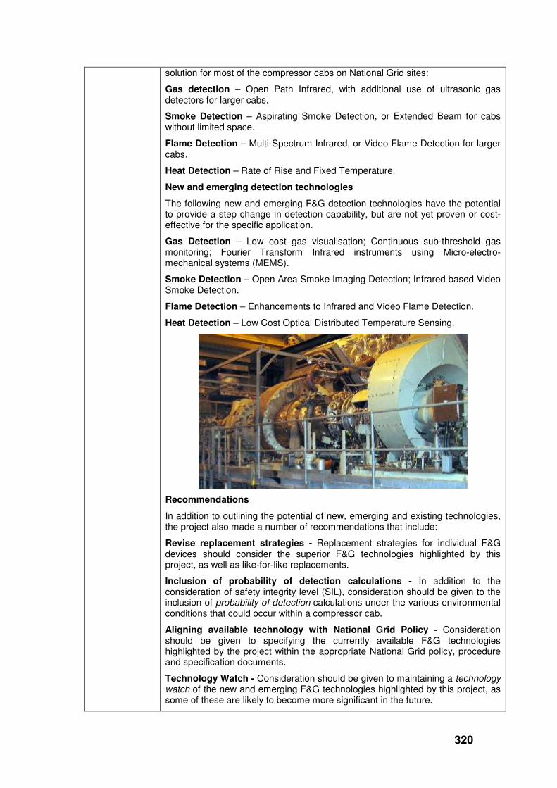
Compressor cab design has evolved significantly in terms of size, layout, ventilation and engine type since the first NTS compressor stations were built in the 1970s.
Running separately to these changes, there is continuous pressure to reduce cab maintenance and to increase the safety of maintenance personnel. For example, many compressor cabs are experiencing higher temperatures due to summer running.
Unfortunately there has not been a corresponding evolution in Fire and Gas (F&G) protection philosophy, or any significant uptake for new types of F&G detection systems that could more effectively address the changes outlined above. As a result, the F&G protection philosophy and the types of detection systems being used have been broadly transferred from one installation to the next. This means that, for many compressor cabs, the F&G systems are no longer optimised in terms of the following issues:
Performance - Ceiling mounted devices are exposed to severe temperature regimes.
Reliability - Traditional devices do not meet the recommended Safety Integrity Level for the environment.
Operating regime - Use of high powered ventilation fans.
Ease and Safety of Maintenance - Elevated locations and requirement for periodic maintenance with greater frequency.
Number of Devices - Use of multiple detectors to increase chance of detection and tendency to add new devices, rather than replace traditional devices.
This project will therefore review a number of potential techniques that have not yet currently been deployed or evaluated for use as fire and gas detection sensors on UK transmission pipeline compressor stations.
Project Benefits Rating
Project Residual Risk
Overall Project Score
Type(s) of innovation involved
Tech Transfer
17 -1 18
319
Expected benefits of project
1. Improved performance of fire and gas safety protection on compressor stations
a. Increased ability to achieve target SIL (safety integrity level) - for example by using self-diagnostics to prevent operation with hidden failures to sensors and associated systems.
b. Increased sensitivity where required - for example where traditional devices provide insufficient sensitivity in highly ventilated compressor cabs.
c. Increased performance - for example by avoiding ceiling locations where sensors can be affected by high temperature.
2. Reduced safety risk for maintenance operatives - for example by avoiding elevated locations and, where these are necessary, reducing the frequency of intervention.
3. A typical compressor cab may have as many as 20 fire & gas detectors, many of which require regular periodic maintenance to validate their performance. The cost of maintaining these devices (often in hard to reach locations and requiring the hiring of scaffolding or raising platforms) can amount to several thousand pounds per year per compressor unit.
4. The total cost of a control and instrument refit on a compressor station is targeted at about £5m per station. To catch up on the delayed programme of refits, it may be necessary to carry out several station refits per year over the next few years. Fire & Gas detection is an important part of the refit and may account for as much as £0.3m per compressor unit (Typically 2 – 3 units per station). The project will look to identify opportunities to reduce this cost, but the outcome could also be that National Grid benefits from better value (required safety integrity level, required sensitivity and increased performance) for a similar cost outlay.
Expected timescale of project
1 year Duration of benefit once achieved
5 years
Probability of success
60% Project NPV = (PV benefits – PV costs) x probability of success
£32k
Potential for achieving expected benefits
New and emerging F&G devices that provide enhanced performance, reliability and reduced maintenance requirement have been identified as meeting the main objectives of this project. In addition, recommendations have been made detailing the most appropriate combination of new F&G devices that would best suit the layout and configuration of the different compressor cabs on National Grid’s transmission network.
The potential for achieving the expected benefits is considered to be high, subject to the timescales of an implementation programme. It is likely that the implementation programme will be aligned to the existing investment scheme for periodic control system and F&G refits.
Project progress
[Year to End of March 2012]
The project found that most of the F&G detection devices installed on National Grid sites were the traditional types, with their inherent weaknesses. Therefore, considerable performance and maintenance benefits could accrue by upgrading to best-of-breed devices currently available.
Existing detection technologies
The following existing F&G detection technologies could provide a generic
320
solution for most of the compressor cabs on National Grid sites:
Gas detection – Open Path Infrared, with additional use of ultrasonic gas detectors for larger cabs.
Smoke Detection – Aspirating Smoke Detection, or Extended Beam for cabs without limited space.
Flame Detection – Multi-Spectrum Infrared, or Video Flame Detection for larger cabs.
Heat Detection – Rate of Rise and Fixed Temperature.
New and emerging detection technologies
The following new and emerging F&G detection technologies have the potential to provide a step change in detection capability, but are not yet proven or cost-effective for the specific application.
Gas Detection – Low cost gas visualisation; Continuous sub-threshold gas monitoring; Fourier Transform Infrared instruments using Micro-electro-mechanical systems (MEMS).
Smoke Detection – Open Area Smoke Imaging Detection; Infrared based Video Smoke Detection.
Flame Detection – Enhancements to Infrared and Video Flame Detection.
Heat Detection – Low Cost Optical Distributed Temperature Sensing.
Recommendations
In addition to outlining the potential of new, emerging and existing technologies, the project also made a number of recommendations that include:
Revise replacement strategies - Replacement strategies for individual F&G devices should consider the superior F&G technologies highlighted by this project, as well as like-for-like replacements.
Inclusion of probability of detection calculations - In addition to the consideration of safety integrity level (SIL), consideration should be given to the inclusion of probability of detection calculations under the various environmental conditions that could occur within a compressor cab.
Aligning available technology with National Grid Policy - Consideration should be given to specifying the currently available F&G technologies highlighted by the project within the appropriate National Grid policy, procedure and specification documents.
Technology Watch - Consideration should be given to maintaining a technology watch of the new and emerging F&G technologies highlighted by this project, as some of these are likely to become more significant in the future.

321
Site-specific risk assessments - It is recommended that a detailed site-specific risk assessment is always undertaken to determine the final deployment details of the fire and gas detection devices highlighted by this project.
Collaborative partners
None
R&D provider GL Noble Denton

322
Infrastructure
Project title Detection & Management of Corrosion on Above Ground Insulated Pipework and Pipe Supports
Project Engineer
Peter Martin
Description of project
The project will produce:
• A market review of corrosion inspection systems for pipework and pipework supports that are normally covered by insulation materials.
• A practical evaluation of the most applicable corrosion inspection system(s), established by the market review.
Expenditure for financial year
Internal £8k
External £11k
Total £19k
Expenditure in previous (IFI) financial years
Internal £10k
External £111k
Total £121k
Total project costs (collaborative + external + NG)
£140k Projected 2012/13 costs for NG
£0
Technological area and/or issue addressed by project
The issue being addressed by this project is the condition of pipework on above ground facilities. External corrosion can develop and be hidden under noise insulation cladding or between the pipe and its mechanical supports. Complete removal and refitting of all insulation cladding and pipe supports to allow thorough inspection is prohibitively expensive. Sample removal does not guarantee that all corrosion is identified. Therefore, alternative methods are required to locate areas of hidden corrosion without removal of insulation cladding or dismantling of pipe supports.
Project Benefits Rating
Project Residual Risk
Overall Project Score
Type(s) of innovation involved
Tech Transfer
14 -3 17
Expected benefits of project
By using new inspection systems, National Grid will benefit in a number of ways:
1. Non-invasive inspection techniques will allow 100% coverage of assets, resulting in improved confidence in above ground pipework integrity and identification of problem corrosion prior to failures (and their associated impacts on safety, security of supply and the environment)
2. Invasive maintenance can be targeted only where it is needed, leading to a faster conclusion to remedial action programmes, followed by reduced maintenance costs in the future.
3. National Grid can demonstrate to the Certifying Authority (HSE) that they are using the best available technology to improve safety on above ground installation (AGI) sites.
Expected timescale of project
3 years Duration of benefit once achieved
5 years

323
Probability of success
60% Project NPV = (PV benefits – PV costs) x probability of success
-£57k
Potential for achieving expected benefits
The results of both the in-house and onsite trials have demonstrated that the Hydrotector system can be refined to produce accurate information on the condition of the insulation material (in terms of saturation level and location) under lagging. This has potential benefits for National Grid in terms of a significant cost saving in time and materials through a more focussed inspection regime.
The work has now been completed and National Grid should consider using the Hydrotector system as an additional tool to assist with the inspection of above ground lagged pipework.
Project progress [Year to End of March 2012]
The initial in-house trails with the Hydrotector unit to evaluate the effects of variables such as temperature and humidity enabled a set of graphs to be drawn up for use when using the Hydrotector unit on site to inspect above ground lagged pipework.
A subsequent 10 month on site trial using the above graphs in conjunction with the Hydrotector, confirmed that the Hydrotector system can be used successfully for detecting both sections of wet lagging and the level of saturation of the lagging.
These findings have enabled the Hydrotector results to be viewed with a greater confidence, allowing the removal of lagging to be more focussed on areas where corrosion is most likely to be present. This could provide a significant cost saving and National Grid should consider implementing an inspection programme using the Hydrotector system to inspect lagged pipework on above ground installations (AGI’s).
In November 2011, GL produced report 11311 detailing the Hydrotector work and made a number of recommendations, some of which are listed below:
� Improvement in inspection results to meet the T/PM/CM/4 (CM/4) Management Procedure Specification.
� Significant cost savings in time and materials through a more focussed inspection regime.
� Demonstration to the HSE that National Grid is addressing the problem of corrosion under insulation in a novel and cost effective manner.
Collaborative partners
None
R&D provider GL Noble Denton

324
Project title Optimisation of Integrity Management at Sleeved Crossings
Project Engineer
Rob Stockley / Joanne Harris
Description of project
This project is looking into alternative fills for the 1100 Nitrogen sleeves that were installed on the NTS in the 60’s and 70’s. The valves and rubber hoses connecting the sleeves have begun to perish and difficulties exist in maintaining pressure. This project will look to address that issue.
Expenditure for financial year
Internal £11k
External £28k
Total £39k
Expenditure in previous (IFI) financial years
Internal £9k
External £89k
Total £98k
Total project costs (collaborative + external + NG)
£137k Projected 2012/13 costs for NG
£0
Technological area and/or issue addressed by project
The aim of the project is to carry out research in order to determine:
• Alternative solutions to the use of nitrogen for providing an inert atmosphere and seal within the sleeve. This should include a review of research carried out and the evidence available to prove a products fitness for purpose and long term performance. It should also consider the level of proven operator experience.
• International best practice on sleeve management, picking up on the techniques currently being employed within the European gas industry.
Project Benefits Rating
Project Residual Risk
Overall Project Score
Type(s) of innovation involved
Incremental
12 0 12
Expected benefits of project
The purpose of this project is to determine and quantify the potential benefits for the UK gas transmission system using alternative methods for providing an inert atmosphere within existing pipe sleeves and to identify the costs of these alternative techniques, ease of installation, ongoing maintenance requirements, performance and overall reliability compared to current practice. The work includes a review of the appropriate fill mechanism for each product.
Expected timescale of project
3 years Duration of benefit once achieved
5 years
Probability of success
60%
Project NPV = (PV benefits – PV costs) x probability of success
£20k
Potential for achieving expected benefits
Potential to achieve expected benefits is good. Successful identification of two alternative casing fillers, which are set to be trialled in the field, resulted from information gathered on:
� Performance
� Cost
325
� Practical experimental experience
� The integrity management approach of other operators
Project progress [Year to End of March 2012]
In the initial phase of this project eight materials were identified as replacements to nitrogen for use as an alternative fill for pipe sleeves. The materials varied from gels to viscous fluids to gases, and were all selected due to their corrosion control capabilities as well as their ability to be injected into pipe sleeves through existing connections with minimal alterations where necessary.
After further consideration, four replacement materials consisting of alternative fill gases were removed from the list of options due to issues with maintaining pressure. The remaining four materials consisting of gel or viscous fluid were agreed to have potential as replacements for nitrogen as casing fillers in sleeved crossings. Two of the four casing fillers are petroleum based compounds; one is a polymer based compound and the other is vapour phase based.
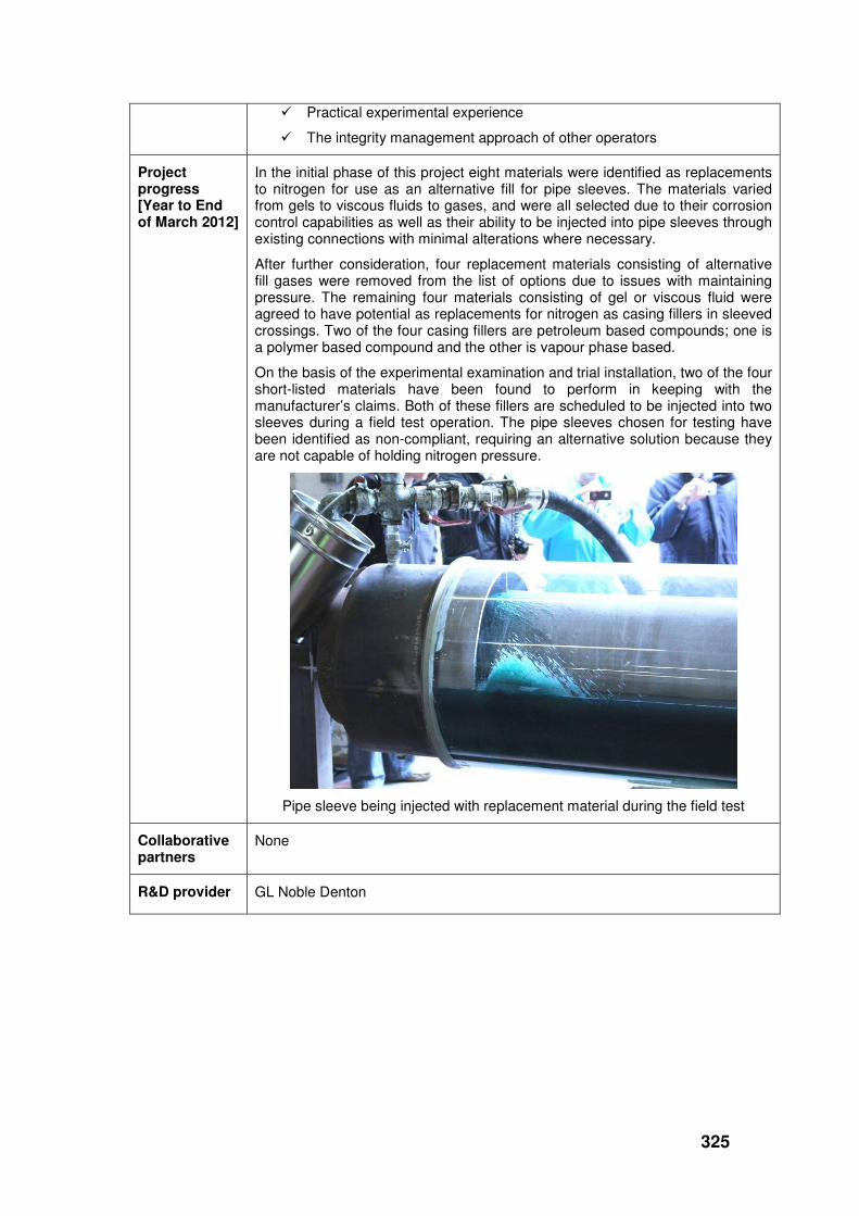
On the basis of the experimental examination and trial installation, two of the four short-listed materials have been found to perform in keeping with the manufacturer’s claims. Both of these fillers are scheduled to be injected into two sleeves during a field test operation. The pipe sleeves chosen for testing have been identified as non-compliant, requiring an alternative solution because they are not capable of holding nitrogen pressure.
Pipe sleeve being injected with replacement material during the field test
Collaborative partners
None
R&D provider GL Noble Denton

326
Project title Development of AC Over Line Survey System
Project Engineer
Peter Martin
Description of project
This project will deliver a suitable over line AC survey system that will be used for the initial identification of areas where the levels of AC interference on gas pipelines may require mitigating action. When implemented, the survey system will enable the improved detection and assessment of AC-induced corrosion in gas pipelines, thereby reducing the likelihood of leakage or failure though this particular corrosion process
Expenditure for financial year
Internal £7k
External £59k
Total £66k
Expenditure in previous (IFI) financial years
Internal £7k
External £121k
Total £128k
Total project costs (collaborative + external + NG)
£317k Projected 2012/13 costs for NG
£124k
Technological area and/or issue addressed by project
AC corrosion has been documented in the UK, mainland Europe and North America. Through-wall failures have been recorded and corrosion rates as high as 1.4 mm/yr calculated. A 2004 report indicates that 24 known cases of AC corrosion were reported in Europe (but likely that this is only a small percentage of the total). These pipelines were not shown to have any defects during conventional DC CIPS surveys. Increasing installation of power lines, rail transit systems and improvements to pipeline coating quality will all continue to increase AC corrosion instances.
Project Benefits Rating
Project Residual Risk
Overall Project Score
Type(s) of innovation involved
Significant
12 6 6
Expected benefits of project
The business benefit is attained through developing a clear view of the levels of AC interference along a pipeline, rather than just at the test points (as is presently the case). Through this process, mitigation measures can be applied, if necessary, enabling the issue to be effectively monitored and controlled. The potential order of magnitude of costs ‘avoided’ are outlined above.
Expected timescale of project
3 years Duration of benefit once achieved
5 years
Probability of success
90% Project NPV = (PV benefits – PV costs) x probability of success
£42k
Potential for achieving expected benefits
Based upon the data captured and analysed from the preliminary field trial there is a high potential for this project achieving the expected benefits.
Whilst further trial data is required to fully corroborate the findings to date, and to qualify the technology options, early indications from the data suggest that the technology can identify areas of high current density.

327
Project progress
[Year to End of March 2012]
The project experienced a significant delay in the availability of the candidate field device and the custom design, development and build of the prototype AC module.
Development of trailing cable technologies
Further theoretical physics work was conducted in relation to electromagnetic inductance on the field device and the impact that this could have on any measurements taken in the field. As a result of this a number of mitigating technology options were explored. This resulted in the design, development and bench testing of 2 trailing cable technologies designed to shield the trailing cable from EM induction.
Bench testing of the trailing cable technologies was undertaken to determine the effectiveness of the shielding technology. The testing took place under controlled conditions using a simulated real world electromagnetic field.
A draft operational procedure was also written for the candidate device and the supporting trailing cable technologies.
Field Testing
Following promising results under laboratory conditions for the candidate device, the prototype AC Module and the 2 trailing cable technologies it was decided to test the technology in the field.
Bad weather conditions in December and January added some further delays to the project. However, in early March the first field trial was conducted on the pipeline adjoining Stallingborough Power Station. This pipeline has experienced AC corrosion in the past and it is known to have very high levels of AC current and voltage induced on the pipeline as regularly monitored via test posts / coupons.
The field trial was designed to test 3 cable technologies with the candidate device and the associated prototype AC module. The cables technologies tested were set out in the following three scenarios:
• Standard MC Miller copper wire as used in a standard CIPS survey for control purposes i.e no shielding from AC inductance
• Specially designed 0.3mm Coaxial cable – Shielded against EM induction
• 2 x MC Miller copper wires in very close proximity combined with a prototype shielding device designed to cancel out any EM inductance / interference

328
MC Miller Candidate device with prototype AC CIPS Module and measurement probes attached during field trail at Stallingborough power station
The following were also tested during the first field trial.
• Usability of the candidate device, and each cable technology
• Deployment of cable technology
• Test the draft operational procedures for the device and the trailing cable technologies in the real world.
• Soil resistivity tests
• Static voltage and current readings
• Test post voltage and current monitoring
• Measurement of the EM field generated by the overhead power lines
A good data set was collected for each of the 3 scenarios and a series of lessons learned were captured.
The MC Miller candidate Device with Prototype AC CIPS Module attached
The initial data has been processed in accordance with the formula identified in the theoretical physics studies and this initial data has now been analysed.
During the first field trial an issue was identified whereby a.c. voltage measurements on the mobile logger were not consistent with those from the

329
static logger. In order to understand this behaviour a second set of tests were performed over part of the same test section.
During this series of tests a number of a.c. current and a.c. voltage measurements were taken at the start point of the survey section. The purpose of these tests was to check for consistency of measurements between devices and also look at the impact of trailing wire configurations on such measurements.
Connecting AC Voltage and Current Readings at the test post at Stallingborough power station
Having established that consistent readings could be recorded with the different devices, further tests were performed to establish the effectiveness of mitigation techniques (twin wire and coaxial cable) against a reference (single strand copper wire).
A comprehensive set of data from the second field trial, for all 3 cable configurations has enabled data analysis algorithms to be further refined. Evaluation of the survey results subsequently lead to 1 of the 3 cable configurations being dropped. In the twin wire configuration additional transformer secondary impedance was found to have an adverse effect on the current readings that is not readily compensated for, hence the omission of the twin pair option.
Bench testing of cable real shielding

330
From the second field trial it has been possible to establish a number of conclusions and recommendations which have been outlined below:
Conclusions
1. Profile of a.c. current and a.c. voltage measurements along the survey route is consistent with expectation
2. Calculated a.c. current values without a spool/coil in circuit exhibit good correlation to reference measurements
3. Calculated a.c. current values with either a single strand copper wire or coaxial cable spool/coil in circuit are under estimates. This is most likely due to estimates of resistance and inductance for the length remaining on the spool at any point being inaccurate
4. Tests over short lengths (up to 200 m) suggest that the induced voltage due to ac fields from overhead power lines are so small that they do not have a measurable effect on the voltage reading.
5. There is no differentiating factor between the cable technologies when considering the impact of the overhead power cables on the measurement of voltage.
6. Any current density measurements taken without compensating for inductance on a coil are not accurate and will significantly underestimate the actual current density at the measurement point.
Sample output of data analysis from the Stallingborough field trail
Recommendations
1. Further refine calculations used to determine coil inductance as these are playing a significant role in the calculation of a.c. current
2. The MC Miller probe used for current measurements does not have a surface area of exactly 1cm2 and needs to be modified (or its true surface area taken into consideration).
3. Modify survey procedure to check that there is no a.c. voltage or a.c. current offset observed between moving logger and static logger prior to the survey commencing
4. Modify survey procedure/software to ensure that particular attention is given to the measurement of trailing wire resistance at the beginning and end of each survey section
5. Modify survey procedure/software to ensure that particular attention is given to estimating the length of wire remaining on each spool at the

331
beginning and end of each survey section
6. Consider the influence of temperature on resistance of the spooled wire. Determine whether this needs to be included in the methodology.
7. Repeat the over line survey at Stallingborough ensuring that the full 500 m section between TP #1300 and TP #1400 is surveyed (using single strand copper wire and coaxial cable)
8. Qualify the impact of the cable packing factor on the inductance of a spool of cable.
9. Instruct cable manufacture to count number of turns and the actual length of cable on the full real within a +/- 5% error of margin.
Further reading is available in the Development of AC Overline Survey – Phase 2 Interim Report, February 2012. Recommendations of this report are currently being written into a revised field trial procedure that will form the basis of the next field trials.
Collaborative partners
None
R&D provider GL Noble Denton

332
Project title Magnetic Tomography Method (MTM) Pipeline Inspection System: Evaluation & Validation
Project Engineer
Peter Martin
Description of project
Conduct field trials to evaluate this new inspection method’s ability to detect significant metal loss features on buried NG pipelines and validate the method’s output by subsequent selected excavation and physical examinations of the pipelines.
Expenditure for financial year
Internal £7k
External £73k
Total £80k
Expenditure in previous (IFI) financial years
Internal £5k
External £70k
Total £75k
Total project costs (collaborative + external + NG)
£373k Projected 2012/13 costs for NG
£218k
Technological area and/or issue addressed by project
Uniqueness of the MTM Technique
None of the techniques, currently employed above-ground to assess the condition of buried pipelines, are capable of locating coating disbondment. However, the MTM technique is now claimed to be able to locate coating disbondment from above ground, and therefore provide similar information to that generated during an in-line inspection (ILI).
MTM technology has been developed to be an innovative, non-intrusive and non-contact method of inspection which can provide 100% inspection of a pipeline from above ground. It is said to be capable of locating pipeline material anomalies, characterizing these anomalies and forecasting the need for follow-up actions
How it Works
The MTM inspection technique has recently appeared in the UK market place and is currently being marketed by Transkor Ltd. The technique measures distortions in the earth’s magnetic field due to the presence of buried objects such as a pipeline. Areas of high stress in the pipeline, cause significant distortion of the earth’s magnetic field that surround the pipeline and these areas of distortion can be detected from the surface. Excavation of these areas can then be made to determine the cause of the distortion. The technique is claimed to have the following advantages over other above ground techniques:
� No need for advanced preparation or change to the pipeline’s operating conditions.
� Suitable for any pipeline regardless of type of construction, type of medium transported and presence of flow.
� Does not magnetize the pipe.
� Reveals metal loss features and cracking.
The technique is claimed to be of particular benefit where metal loss features occur under disbonded coating. Although these features are detectable using ILI tools, none of the above ground survey techniques, currently employed on pipelines, are capable of locating or sizing metal loss features.
Historical Note

333
In 2007/8, the MTM system was trialled in the United States by the NE Gas Alliance of which, National Grid US is a partner. The trial was performed in Manhattan on a number of buried pipelines, but due to problems, the pipes were never excavated to evaluate the MTM results and as a consequence of this the MTM inspection results were not confirmed. Consequently, the MTM system still requires to be evaluated by National Grid to determine the extent of it’s abilities to detect significant features on National Grid pipelines.
Project Benefits Rating
Project Residual Risk
Overall Project Score
Type(s) of innovation involved
Radical
11 0 11
Expected benefits of project
If the MTM system can truly detect the magnetic signature created by significant metal loss on a buried pipeline, the biggest benefit will be that it should enable National Grid to tackle a potentially significant problem that is starting to generate concern.
The potentially significant problem is corrosion, caused by disbondment of the coal-tar coating on buried pipelines (most of the pipeline network is now exceeding its original 40-year design life and coal tar coatings, in particular, are giving rise to concern, because coal-tar is a liquid, albeit a very viscous one). Where disbondment occurs, water tends to seep between the pipeline and its coating by capillary action, where it forms a “closed” corrosion cell. The significance of it being a “closed” corrosion cell is that cathodic protection does nothing to reduce the rate of corrosion (CP only works to reduce corrosion of exposed defects).
The standard approach to identifying and controlling corrosion on buried pipelines is to conduct in-line inspection (ILI) surveys every 14 years. Where sub-critical defects are detected by ILI, the level of cathodic protection is increased in conjunction with ‘close intervals potential surveys’ (CIPS), which are undertaken much more frequently.
A typical pipeline may have up to 3000 sub-critical defects. 70% of pipelines are coated with coal-tar. International experience suggests that as much as 20% of corrosion defects may be caused by disbondment. However, National Grid has no current method to confirm this. Safety considerations dictate that National Grid cannot afford to wait 14 years to measure corrosion rate of defects over the period between two ILI surveys. CIPS can detect the location of lowest potentials but cannot diagnose the nature of the corrosion and CP will do nothing to halt or delay the corrosion in a “closed” corrosion cell.
If MTM works, it could be used to conduct surveys from the surface during the 14 year interval between ILI surveys. It may be able to characterise coating disbondment on a single survey. Alternatively, if successive MTM surveys showed continuing metal loss despite CP levels being raised, this could indicate a corrosion mechanism that is not affected by CP (e.g. a “closed” corrosion cell caused by coating disbondment). The metal loss could then be monitored by MTM until the defect became critical, at which point National Grid would dig down and repair the pipeline.
Without MTM surveys (or a comparable solution), National Grid has no way of knowing how extensive is the problem of “closed” corrosion cells caused by coating disbondment. If coating disbondment is a significant problem, National Grid then has no way of monitoring it during the 14 years between ILI surveys. In order to manage the risk to the public of pipeline failure from this type of corrosion, National Grid would be required to either increase the frequency of ILI surveys or dig down and visually inspect the worst of the 3000 or so sub-critical defects on the typical pipeline.

334
The increased “pig and/or dig” activity would lead to an escalation in maintenance costs that National Grid would be keen to avoid:
� Typical ILI survey cost for a pipeline (including disruption to network capacity): £80k – £100k.
� Typical excavation cost: £20k – £30k (occasionally rising to £250k in mountainous areas).
� Indicative cost of MTM service (equipment hire, plus qualified operator and provision of analysis): £30k /month.
National Grid is currently part way through an aggressive CIPS survey programme covering a significant percentage of the network. For example, this has highlighted 22 defects that warrant further investigation on Feeder No.12 in Scotland between Aberdeen and Glenmavis. If MTM works, it could be used to prioritise any subsequent dig activity. Another example would be No.2 Feeder between Dowlais and Dyffryn in Wales. This is a coal tar coated pipeline in a mountainous region, where dig activity would be at a premium.
If the project is successful, NGG Transmission might reasonably expect in the course of 10 years to delay by an average of 5 years the cost of digging down to further investigate 1% of the current total 38,000 sub-critical defects. The cost of hiring the MTM kit for 4 months each year would be around £120k per year.
Expected timescale of project
2 years Duration of benefit once achieved
5 years
Probability of success
85% Project NPV = (PV benefits – PV costs) x probability of success
£26k
Potential for achieving expected benefits
Results from the first MTM trials were compared directly to In Line Inspection (ILI) tool results by overlaying both data sets onto an Uptime pipeline map. This enabled the results to be directly compared and confirmed that there was a correlation between both data sets.
The results indicate that the MTM system has the potential to inspect a buried pipeline from the surface and locate metal loss features and to identify stress deformed pipeline sections due to ground movement.
The MTM system is also a non intrusive method of pipeline inspection and, coupled with results obtained for this first set of site trials, it appears to have great potential for National Grid and other Oil and Gas majors for pipeline inspection.
Project progress [Year to End of March 2012]
Between February and April 2011, the MTM system was used successfully to inspect the 6 sections of chosen pipeline, having a total length of approximately 10kms. The pipeline sections had previously been inspected with an In Line Inspection (ILI) tool and the ILI data was available for comparison with the MTM results.
Following completion of the onsite trails, an MTM inspection report was produced and the MTM results were overlaid on top of the ILI data using National Grid’s Uptime system. This produced a set of pipeline maps that has enabled a direct comparison to be made between the two sets of data. Two of these maps have been provided in this report for your reference.

335
Uptime Map for the Dowlais to Dyffryn Clydach Pipeline-Forest Section.
Uptime Map for the Roundham Heath to Gt Wilbraham Pipeline-Forest Section.
Evaluation of the two data sets has shown that there is a good correlation between the locations of the pipeline anomalies.

336
All of the information and results obtained from the site trials was recorded and discussed in a GLND report No.13110, issued in December 2011. The report concluded that:
“These initial MTM trials suggest that the MTM system has potential to inspect a buried pipeline from the surface and locate metal loss features as well as to identify stress deformed pipeline sections due to ground movement. However, in order to improve NGG’s understanding of the MTM system’s true performance, further trials should be considered”.
Based on these results and the potential of the MTM system to National Grid, and following discussions with National Grid, in March 2012, GL applied for further IFI funding to perform a second set of trials to inspect sections of National Grid pipeline where known ILI features were located. These features were scheduled to be excavated for a P11 assessment. The MTM system to be used for these latest trials would be a “Mark 2” system that had been updated from the original unit as used on the first set of trials for National Grid.
Collaborative partners
None
R&D provider GL Noble Denton

337
Project title Ledeen Valve Actuator Tie Rod Condition
Project Engineer
Steve Johnstone
Description of project
The project aim is to inform National Grid on how the severity of valve actuator tie rod deterioration contributes to the risk of failure within the substantial population of scotch yoke design valve actuators fitted with piston cylinders held in place with external tie-bars installed on the NTS. It is understood that similar failures in the upstream sector have presented a significant safety hazard to maintenance operatives, and generated concerns over the reliability of this design of valve actuator.
Expenditure for financial year
Internal £7k
External £22k
Total £29k
Expenditure in previous (IFI) financial years
Internal £5k
External £10k
Total £15k
Total project costs
(collaborative + external + NG)
£44k Projected 2012/13 costs for NG
£0
Technological area and/or issue addressed by project
A number of Ledeen double acting scotch yoke gas/hydraulic type actuators, some of which are over 30 years old, are to be removed during decommissioning of Bathgate Compressor Station. These actuators have been found to be in very poor condition. Of particular interest are the tie rods holding the piston cylinders to the actuator bodies, which have significant material loss due to severe corrosion.
A HSE safety bulletin reported a spring return ESD valve actuator failure on an offshore facility. This failure rendered the platform isolation device inoperable with the valve failed in the open position. According to ongoing investigation, tie rod failure due to corrosion led to the release of the end plate and subsequent spring release at velocity propelled by stored energy. Consequently, the HSE recommends, among other things, that:
a) Valves are to be inspected to ensure that the spring housing and retention tie rods are fit for purpose with particular attention being paid to open ended tie rods which may accumulate dirt and moisture.
b) Maintenance regime is to include adequate inspection of the actuator.
c) Coating and seal maintenance programme be carried out to prevent corrosion.
d) The suitability of retaining tie rods and end plates on spring return valves is reviewed given the potential for moisture accumulation and difficulty in condition inspection.
National Grid Gas Transmission is concerned that this design of actuator could potentially fail in a similar way to the above-mentioned offshore spring return ESD valve actuators. Their concern has been heightened by the observation of significant corrosion on the valve actuators at Bathgate.
Project Benefits Rating
Project Residual Risk
Overall Project Score
Type(s) of innovation involved
Incremental
10 -3 13

338
Expected benefits of project
Several hundred scotch yoke design of actuators are currently in service on the NTS. This project will inform National Grid on the how the severity of valve actuator tie rod deterioration contributes to the risk of failure, so that their modification or replacement can be prioritised by in-situ assessments, conducted as part of the periodic maintenance programme.
As well as the direct threat to maintenance operatives in close proximity to a valve actuator undergoing this type of failure, the failure of a valve to operate reliably can increase the threat to safety and the environment from loss in integrity or reduce the availability of capacity.
Increased awareness of the risk of failure associated with tie rod and actuator cylinder deterioration will also help to ensure that sufficient budget is made available to cover any significant replacement or modification costs.
Expected timescale of project
1 year Duration of benefit once achieved
5 years
Probability of success
60% Project NPV = (PV benefits – PV costs) x probability of success
-£27k
Potential for achieving expected benefits
The number of valves at Bathgate represents a small sample of the total population of this type of valve actuator design on the NTS. However, the Bathgate examples do appear to be in poor condition and are of an age that is not untypical of many others. It is expected that the project should at least deliver an assessment of how soon the Bathgate valve actuators would need to be replaced or modified. The project should also develop and demonstrate a suitable methodology for opportunistic collection of further evidence during subsequent decommissioning activity, it may also be necessary to conduct similar tests on spring return actuators as these offer a higher risk potential in comparison to the hydraulic double acting actuators.
Project progress [Year to End of March 2012]
HSE reports were reviewed on the failure of a spring return valve actuator in the offshore industry. Documents referenced by the HSE highlighted that tie rods on actuators can be exposed to corrosion degradation, such that the following are recommended:
a) Plant owners should have a procedure for assessing the integrity of actuator and tie rod coating.
b) Coating replacement in the event of coating damage.
c) Limits on extent of thread degradation.
Summary of findings following the completion of the test programme:
• Tested actuator tie rods have failed in a ductile manner meaning it is likely that the cylinder will leak as a result of tie rod yielding prior to failure.
• Theoretical calculations demonstrate that significant corrosion is possible before yielding of the tie rods under normal operation will occur.
• It is suggested that the minimum tie rod diameter required to withstand the maximum cylinder rated pressure should be conservatively taken as 70% of the original diameter.
In conjunction with existing guidelines for integrity of pressurised systems, bolted joints and existing maintenance policy, it is imperative that a dedicated guideline for monitoring the condition of actuator tie rods is available to ensure valve actuators are maintained in a safe condition. The following table shows the acceptability criteria for actuator tie rods regardless of the return mechanism. This has been designed to fit in the existing National Grid CM/4 procedure.

339
Actuator and tie rod coating inspection and acceptability
† Remove all trace of corrosion before recoating in accordance to National Grid specification T/SP/PA/10 [15].
†† Ensure that paint/coating does not close the gap between the tie rod stem and cylinder, as this would create a collection point for debris and possibly form a corrosion cell. Ensure that all work is executed in accordance with National Grid specification T/SP/PA/10.
††† Tie rod diameter should be measured in various directions and minimum size recorded and compared with original un-corroded size. Percentage reduction in tie rod diameter should be obtained as shown below.
% reduction in diameter/size = (Original – Corroded)/ Original *100
Visual Grade
Description Photo Examples
1 Tie rod and cylinder including bolted ends painted or coated.
In excellent condition with no visible signs of corrosion.
No remedial action required.
2 Tie rod and cylinder paint/coating broken down or visual signs of the onset of corrosion without significant levels of corrosion product or significant metal loss.
Clean and recoat actuator, tie rods, nuts and cylinder. †, ††.
Monitor and record as a CM/4 fault.
3 Tie rod and/or cylinder paint/coating broken down with signs of significant metal loss.
Tie rod bolt heads and nuts with less than 10% across flats dimension loss.
Tie rods showing less than 30% corrosion metal loss in the shank diameter
Recoat cylinder and tie rods. †,††, †††.
Record as a CM/4 fault.
4 Tie rod bolt heads and nuts with 10% across flats dimension loss.
Tie rods showing 30% corrosion metal loss in the shank diameter. †††.
Replace all with appropriate new tie rods. ††††.
Record as a CM/4 fault.

340
†††† Ensure that the defective tie rods are replaced as a set with the correct material.
Collaborative partners
None
R&D provider GL Noble Denton

341
Project title Pit Wall Transitions (PWT) Inspection Technologies
Project Engineer
Wayne Lawson
Description of project
The primary aim of the project is to identify an appropriate and reliable inspection technique for identifying corrosion within Pit Wall Transitions (PWT). This work involves a full and detailed report on findings together with a presentation to include recommendations of the best available techniques to National Grid which are worthy of further investigation. Selected techniques have been assessed further in a simulated environment at PMC Ambergate.
Technology tested previously did not prove reliable in an operational environment. However, due to technology development we anticipate that there may now be appropriate techniques available to identify the level of corrosion within PWTs and therefore successfully determine the need for removal or replacement (under T/PM/CM/4 Grade 4 or 5).
The outcome of this project will form the basis of a wider scheme of works to assess, evaluate and repair all identified PWT faults on the NTS as required.
Expenditure for financial year
Internal £17k
External £20k
Total £37k
Expenditure in previous (IFI) financial years
Internal £5k
External £13k
Total £18k
Total project costs (collaborative + external + NG)
£55k Projected 2012/13 costs for NG
£0
Technological area and/or issue addressed by project
The non-invasive inspection techniques (LRUT) currently used have not proven to be reliable in quantifying the metal loss due to corrosion on hidden pipe work running through pit wall transitions on above ground facilities. Because of this unreliability inherent in the existing inspection techniques, we are limited to the option of PWT removal, regardless of actual need, due to a lack of substantiated evidence.
T/PM/CM/4 requires the following remedial action by visual grade:
Grade 4: Perform guided wave inspection and assess results.
Grade 5: Perform guided wave inspection and assess results. Consider removal/replacement of pit wall transition.
Grade 6: Guided wave inspection has shown indication of corrosion damage. Remove and replace PWT and repair pipeline as appropriate.
The term guided wave inspection is a generic expression used to describe the technologies being assessed in this project. It is anticipated that the experience built up by a number of competing techniques under review, with various refinements around the world, will provide a suitable technique that National Grid can use to successfully determine which Grade 4 or 5 pit wall transitions require either removal or replacement.
Project Benefits Rating
Project Residual Risk
Overall Project Score
Type(s) of innovation involved
Significant
14 -2 16

342
Expected benefits of project
A number of Terminals/Compressor stations have identified a significant amount of PWT features (approximately 50–60) that require further investigation. These have all been recorded on the Plant Status Register.
Without a suitable technique in place the only alternative is to continue to excavate all PWTs (of the approximately 50-60 mentioned above) based exclusively on their score in the plant status register. Any excavation works undertaken will require pressure reduction, outages and other flow constraints on the NTS resulting in a significant cost to the business.
If an appropriate technique is identified and approved during the course of the project, this would make it possible to test and assess PWTs without the need for excavation. Thereby providing greater confidence in establishing the condition and integrity of the pipe work within the PWT. Historical information indicates that this advancement could allow for a potential cost savings of £125 - 135k per PWT.
In addition, the utilisation of an approved technique will allow for further cost benefits when calculating business costs based on the ability to identify the percentage of PWTs that can be kept in their current state for an extended period of time, where they would otherwise need to be repaired straight away.
Expected timescale of project
2 years Duration of benefit once achieved
5 years
Probability of success
60% Project NPV = (PV benefits – PV costs) x probability of success
£241k
Potential for achieving expected benefits
Following the short listing and trials conducted at PMC Ambergate, the potential for achieving benefits from the project results have met all expectations. An organisation (SPI–MATRIX) has been identified as being a service provider with the potential to meet business expectations moving forward.
Project progress
[Year to End of March 2012]
The project is now fully complete. A full evaluation and report has been undertaken by ABB to identify suitable techniques that are available to National Grid in the current marketplace.
Identifying corrosion within pit wall transitions

343
Recommendations have been made based on results from the test facility trials at PMC Ambergate. It is the recommendation of ABB that SPI–MATRIX meet the criterion set out by National Grid from the outset. The results have been considered and SPI–MATRIX has been used in a ‘live’ incident as an opportunity to test the techniques further.
A presentation, including a challenge and review session, was carried out at National Grid House by SPI-MATRIX to understand the organisation’s wider capabilities.
Collaborative partners
None
R&D provider ABB (Wilton)

344
Project title Effect of Post Weld Heat Treatment (PWHT) on Thermo-Mechanically Controlled Process (TMCP) Steel Pipelines
Project Engineer
Richard Wilkinson
Description of project
Determine whether standard welding procedures can be used on typical high strength TMCP (thermo-mechanically controlled process) steels. The project will identify the extent of possible deleterious effects on two typical TMCP steels by locally re-heating samples of the steel above their critical temperatures using standard PWHT (post weld heat treatment) methods. After they are heated, the samples will be sectioned for mechanical testing to establish any degradation of properties.
Expenditure for financial year
Internal £8k
External £35k
Total £43k
Expenditure in previous (IFI) Financial years
Internal £0
External £0
Total £0
Total project costs (collaborative + external + NG)
£43k Projected 2012/13 costs for NG
£0
Technological area and/or issue addressed by project
Practical options for routeing new or diverted pipelines have lead to the construction of recent pipelines in potentially seismic or land-slip areas. Designers have advocated the use of extra heavy wall pipe in these areas with the possibility that post weld heat treatment of girth welds may be required. Modern high strength TMCP pipeline steels used by National Grid are not designed to be subjected to PWHT and may suffer degradation of mechanical properties if re-heated above critical temperatures.
It is proposed that this project is carried out to identify the extent of possible deleterious effects on typical high strength TMCP steels by locally re-heating the steel above critical temperatures using standard PWHT methods and following sectioning, mechanically test the steel samples to establish any degradation of properties.
Project Benefits Rating
Project Residual Risk
Overall Project Score
Type(s) of innovation involved
Incremental
19 -4 23
Expected benefits of project
The ability to make an informed decision when PWHT is required or specified by the pipeline designers will allow the selection of the most appropriate and cost effective welding process and procedures to be made. This could result in a saving on construction welding costs for special sections in landslip areas of approximately 400%.
A typical cost for a 48”OD heavy wall welding procedure test is circa £4k, so potential savings could be as much as £16k per diversion in landslip areas. A reasonable expectation would be that this amount would be saved about once every two years. However, if there was another significant pipeline project through high landslip potential country (e.g. a second Milford Haven feeder), the savings would be higher and concentrated within the pipeline project timescales.
Expected timescale of
1 year Duration of benefit once achieved
5 years

345
project
Probability of success
90%
Project NPV = (PV benefits – PV costs) x probability of success
£1k
Potential for achieving expected benefits
Current forecasts predict that there may be a need to reinforce Feeder 28 from South Wales. Should a new pipeline be routed onshore, limited available corridor routes could result in construction through known landslip areas. In keeping with initial benefit projections, the knowledge gained from this work will be beneficial in the planning and costs associated with the South Wales project, as well as any future projects which undertake work in landslip areas.
Project progress [Year to End of March 2012]
This project has been completed with the final MACAW report 5553 Issue 02 delivered in January 2012.
A detailed evaluation of the effect of PWHT on two TMCR materials has been performed. The steels tested were L450MB and L555MB grade pipe of size 1219mm x 25.4mm, and 1219mm x 22.9mm respectively. The investigation incorporated testing of the pipe body, longitudinal seam weld and girth welds produced in both pipe materials manufactured specifically for this project at the National Grid Pipeline Maintenance Centre at Ambergate.
Summary of findings
All testing in the PWHT condition met the requirements of the pipe and girth weld specifications.
The data generated in this work suggests that a PWHT temperature of 620�C may be too high for pipe manufactured using the type of TMCR plate material investigated. A rationalisation of maximum limits for PWHT cycles may be possible based on this work and existing recommendations. However, further work, as identified in the recommendations below, is required to accurately define the effects of PWHT and recommend specific limits.
Preparation for weld test

346
Completed weld test
Recommendations
1. It is recommended that the use of PWHT on TMCP pipe materials is restricted, and for cases where PWHT cannot be avoided testing should be performed on the specific material to define any deleterious effect on the pipe body, pipe seam weld and girth weld at the proposed PWHT temperature and thermal cycle.
2. Engage with plate and pipe suppliers to further define the acceptable PWHT limits for the material investigated in this study.
3. Engage with induction bend manufacturers as to the suitability of TMCR material for subsequent heat treatment, based on research work being performed in this area. Report No 5553 Issue 2 Effect of PWHT on TMCP pipeline steels MACAW Engineering Ltd.
4. Develop additional data across a production quantity to give some statistical relevance to the data. On future projects involving TMCR material, request testing at the pipe mill to identify the effect of PWHT.
5. In order to fully characterise the effect of PWHT on toughness, perform additional Charpy testing to define the transition curves in each condition.
6. Perform an additional testing program to fully define the temperature/hold time limit, below which no effect of PWHT is observed.
7. Consider Charpy testing in the HAZ of the longitudinal seam weld to identify any effect of PWHT in this critical region.
Collaborative partners
None
R&D provider GL Noble Denton

347
Project title Ageing Critical Valve Research
Project Engineer
Steve Johnstone
Description of project
This project looks to establish guidelines for prioritising valve replacements and to develop reliable methods for refurbishing valves. In both cases, the ultimate aim is to reduce the potential future annual cost of valve replacements.
Expenditure for financial year
Internal £6k
External £79k
Total £86k
Expenditure in previous (IFI) financial years
Internal £0
External £0
Total £0
Total project costs (collaborative + external + NG)
£114k Projected 2012/13 costs for NG
£29k
Technological area and/or issue addressed by project
Following an upgrade at Churchover compressor station a number of Cameron ball valves were removed, which provides an opportunity to conduct detailed analysis on the performance and condition of this type of valve. This study complements previous work already carried out on the Cort valves but importantly, the deterioration/condition assessments will be carried out on a valve type that was not covered by the previous work. Two 36” Cameron ball valves have been identified for the assessment – a ‘low duty’ Station valve and a ‘high duty’ unit valve.
A 36” Cort ball valve at Helpston AGI has also been removed from service due to a leak from its ‘Cort’ 3-piece bolted closure joint. The leak was subject to attempted remediation by means of ‘Furmanite’ injection into holes drilled about the circumference of the 3-piece bolted closure joint. This solution has failed over time and the valve was subsequently removed and is currently stored at PMC Ambergate. This valve will be dismantled, examined and compared to previous valve investigations. Dismantling will also allow National Grid and Furmanite the opportunity to conduct a detailed assessment of the earlier attempted remediation.
Project Benefits Rating
Project Residual Risk
Overall Project Score
Type(s) of innovation involved
Incremental
20 3 17
Expected benefits of project
The benefits that can be derived by this project stem from identifying ageing Cameron valves that do not need replacement. The number of Cameron ball valves with more than 30 years service on the NTS is approximately 1000 (between 50mm and 1200mm). Revalidation of each Cameron valve back to T/SP/V/6 could cost in the order of £4k for a typical 30” ball valve. Because of its construction, it is not possible to re-life this type of valve. Replacement of each Cameron valve could cost £200k to £250k per valve.
The number of Cort ball valves with more than 30 years service on the NTS is approximately 700 (between 200mm and 1050mm). Refurbishment / re-life of each Cort valve could cost £100k. Replacement of each Cort valve could cost in a range of £200k to £250k per valve.
Expected timescale of
1 year Duration of benefit once achieved
5 years

348
project
Probability of success
20%
Project NPV = (PV benefits – PV costs) x probability of success
£1,035k
Potential for achieving expected benefits
The benefit potential remains high. Work undertaken to date does not indicate any detrimental impact on the original potential for achieving the expected benefits for this project.
Project progress [Year to End of March 2012]
The valves have been constructed into test vessels by PMC and complete pressure testing and sealant trials are underway
� The Cameron ball valves have been inspected, welded into pressure vessels, and strength tested as per T/SP/V/6 and API 6D with encouraging results.
� The Helpston Cort valve has been inspected, welded into a vessel and pressure tested. Leak paths at various pressures have been identified.
A change control has been submitted and approved to extend the project delivery dates to allow for trial completion.
Valve with stem extension removed and Cameron gearbox fitted
Valve 721512 following vessel construction
Collaborative partners
None
R&D provider GL Noble Denton

349
Project title The Need for Pressure De-rating Prior To In-Service Welding
Project Engineer
Brian Woodhouse
Description of project
This IFI project aims to confirm that hot-tap welding to pipelines operating at pressures above 70 bar can be carried out within sufficient margins of safety to prevent loss of material strength and consequent local bulging due to the effect of high pipe wall temperatures and internal gas pressure acting upon pipe walls.
Expenditure for financial year
Internal £5k
External £40k
Total £45k
Expenditure in previous (IFI) financial years
Internal £0
External £0
Total £0
Total project costs (collaborative + external + NG)
£45k Projected 2012/13 costs for NG
£0
Technological area and/or issue addressed by project
In-service welding is a common maintenance and installation connection practice which generates both economic and environmental benefits by not removing pipelines from service. The T/SP/P/9 procedure, first published in 1984, specifies pipeline pressure “to be reduced to the minimum practicable”. This programme is a benchmark study which looks to address whether elements of the procedure should be amended in light of material and technological developments over the past 20 years.
Other published standards such as BS 6990 and EEMUA 185 will also be reviewed. The BMT Fleet Technology’s hydrogen diffusing modelling tool, along with data collated on variation in material properties with temperature, will be used for this analysis.
Project Benefits Rating
Project Residual Risk
Overall Project Score
Type(s) of innovation involved
Incremental
15 -4 19
Expected benefits of project
The principle driver in this case is safety. When welding onto a live gas pipeline the pipe is preheated up to 250°C and then welded during the time it takes for the pipe temperature to cool down to 150°C. The preheat and welding cycle is repeated until the joint has been completed. If excessive temperatures are encountered, together with the internal pressure, this could lead to bulging of the pipe. In extremes cases this could even lead to a blow-out. This project looks to determine whether a certain combination of worst-case conditions might lead to a problem, using some simplified analysis to try and predict whether blow-out is likely to be an issue or not.
Therefore this project has the potential to avoid loss of life, remedial costs, shipper penalties and loss of company reputation in the event of a pipeline failure while carrying out in-service pipeline welding.
There is a business benefit in establishing whether the following three procedures are consistent and appropriate for current National Grid operations given the use of new materials and changing network conditions:
• T/SP/P/9
• BS 6990

350
• EEMUA 185
Hot tap welding is carried out approximately five times per year on the National Transmission System (NTS). There is cost associated with this activity related to pressure constraints (i.e. buyback costs £500,000 /day). In most instances there is a need to reduce gas flow rate to allow P/9 welding to take place, this could result in decreased pressures.
Expected timescale of project
1 year Duration of benefit once achieved
5 years
Probability of success
80%
Project NPV = (PV benefits – PV costs) x probability of success
-£37k
Potential for achieving expected benefits
This project ascertained that, for the three line pipes assessed in this work, no pressure reduction is required during hot tap welding, provided the safe guards in the P9 procedure are correctly followed.
Project progress [Year to End of March 2012]
There were two key tasks for this project:
1. A detailed review of the existing safeguards in P9 and a comparison with other published standards, a selection of published papers on work sponsored by Pipeline Research Council International (PRCI) and Australian Pipeline Industry Association (APIA) and a literature search to determine the appropriate strength versus temperature property data for typical line pipe steels.
2. A welding simulation using finite element analysis (FEA) to assess numerically the requirements for pressure reduction during hot tap welding.
Hot-tap welding to pipelines operating at pressures above 70 bar
Based on GL Noble Denton Report Number 12406 and on the review conducted by 5G Orbital, it was concluded that “the welding practices embodied in P9 are arguably the best protection against blow-out”.
1 Several changes to pipe wall
thickness as defined in P9 were suggested and conservative analyses undertaken using recommended elevated temperature tensile properties showed that the following three line pipes have sufficient margins against collapse.
1 A Review of Precautions for Prevention of Blow-Out During In-Service Welding
Onto Pipelines – With an Emphasis on Pressure Derating Requirements

351
Collaborative partners
None
R&D provider GL Noble Denton

352
Project title Development of Novel Mitigation Methods for High Frequency Main Pipework Vibration
Project Engineer
Brian Woodhouse
Description of project
A review of available techniques associated with mitigation against high frequency pipe wall vibration, and the development of a new concept of a grouted ring solution into a working prototype.
Expenditure for financial year
Internal £5k
External £21k
Total £26k
Expenditure in previous (IFI) financial years
Internal £0
External £0
Total £0
Total project costs
(collaborative + external + NG)
£106k Projected 2012/13 costs for NG
£80k
Technological area and/or issue addressed by project
High frequency acoustic excitation of main pipework is characterised by excitation of pipe wall ‘shell’ modes, with local flexing around the circumference and along the length of the pipe section. At high levels this behaviour can lead to acoustic fatigue at welded features such as pipe supports and small bore connections.
Excitation sources which can give rise to this type of internal pipe noise and vibration include blade passing or other periodic excitation or broadband turbulence from centrifugal compressors, high pressure drops from components such as control or pressure relief valves, and vortex-shedding from an obstruction in the flow. Once created the energy from the source can be amplified by acoustic and mechanical resonances, giving rise to high vibration and noise.
Problems associated with this type of response include failure of main pipe welds at local stiffening features, such as blank weldolets/small bore connections and welded pipe supports, and excitation of attached impulse pipework. A number of National Grid compressor sites have experienced problems of this nature.
There are a number of possible mitigation methods which can be used to address this issue depending on the nature of the excitation, including changes to the source such as alteration of compressor impeller clearances or the installation of compressor Helmholtz dampers, installation of acoustic material or a silencer inside the pipe, attachment of external damping material, or welding of stiffening rings to the pipework. The practicality and feasibility of each of these methods depends on what stage in the plant life cycle the problem has been identified.
A new approach is proposed as a possible mitigation method for this behaviour, consisting of a short metal sleeve or ring which is fixed to the outside of the pipe using epoxy grout. This approach would have the benefits of ease of installation and no immediate integrity issues.
Project Benefits Rating
Project Residual Risk
Overall Project Score
Type(s) of innovation involved
Incremental
16 2 14

353
Expected benefits of project
Benefits of carrying out the above study include the following:
1. Reduced risk of vibration-related fatigue failure due to high frequency acoustic noise for compressor station and AGI pipework. Failure of main pipe welds, pipe supports and impulse pipework can be classed as RIDDOR reportable, a serious safety risk as well as potentially leading to large releases of natural gas into the environment.
2. The failure of compressor discharge process/impulse pipework, caused by high dynamic stresses, is likely to cost in the region of £50,000 (including materials, manpower and nitrogen purging). There is also a high risk of a loss of network flexibility with compressor units on outage. Historically these have generated losses of around £50,000. A grouted ring solution could be installed (retro-fitted) with minimal disruption to site operations and has the potential to provide savings in the order of £100k/year.
3. There is an increasing need to monitor vibration across the NTS due to changes in national infrastructure relating to gas inputs and the impact this will therefore have on the use of the NTS. This approach benefits from ease of installation and no immediate integrity issues, allowing for the cost savings achieved when using this new approach.
4. There are the additional environmental benefits of a reduction of radiated noise levels and no requirement to vent the units on installation.
Expected timescale of project
1 year Duration of benefit once achieved
5 years
Probability of success
60% Project NPV = (PV benefits – PV costs) x probability of success
£142k
Potential for achieving expected benefits
The proposed approach has good potential for realisation of the expected benefits.
This project builds on extensive experience with the use of epoxy grout for pipeline repair techniques and offers a method for tackling the identified issue with minimal disruption to operational sites.
Project progress [Year to End of March 2012]
The initial stage of this project has now been completed, comprising of background research into candidate mitigation techniques typically deployed for resolving high frequency pipework vibration problems.
Work to date has covered approaches for tackling the problem at source, methods that can be used during the design and installation phase, and those that can be retro-fitted to existing plant. Findings have been summarised in a review report in which the advantages and limitations of each approach have been considered, together with the relative cost benefits of the techniques and the proposed new approach.
Based on the knowledge gained in the initial stage of this project, as set out in the summary mentioned above, development of the grouted ring concept will commence shortly, through theoretical and experimental studies.
Collaborative partners
None
R&D provider GL Noble Denton

354
Third Party Interference
Project title Installation of IRIS separators
Project Engineer
Paul Sinclair
Description of project
To install IRIS separators in the fuel gas supplies at Carnforth Compressor Station.
Expenditure for financial year
Internal £6k
External £11k
Total £17k
Expenditure in previous (IFI) financial years
Internal £29k
External £227k
Total £256k
Total project costs (collaborative + external + NG)
£273k Projected 2012/13 costs for NG
£0
Technological area and/or issue addressed by project
Trialing the use of a rotary separator that will easily remove liquid contaminants from the fuel gas supply, thus increasing the efficiency and life of the gas generators.
Project Benefits Rating
Project Residual Risk
Overall Project Score
Type(s) of innovation involved
Technology Transfer
11 1 10
Expected benefits of project
There is a mandatory requirement from Gas Turbine OEM’s to provide a clean, dry gas supply system within certain limits. If this requirement isn’t met, the effect is considerable damage to gas generator hot gas path components that cause a loss of efficiency, increased operational, overhaul and repair. Monitoring the amount of liquid removed will determine the schemes success.
Expected timescale of project
4 years Duration of benefit once achieved
5 years
Probability of success
60%
Project NPV = (PV benefits – PV costs) x probability of success
£27k
Potential for achieving expected benefits
There is a high likelihood the IRIS filters will remove liquids if they are present. Currently there remains uncertainty around whether all significant liquid contaminants will be removed from the fuel lines and if there is a potential for detectable reduction in major overhaul frequency for the gas turbine engines.
Project progress [Year to End of March 2012]
Following a number of delays on the project, the preparatory work on the connecting pipe work has been carried out for the installation of the two IRIS separators at the Carnforth compressor station. Further funding is required to complete installation within the 2012/13 compressor station outage.

355
Collaborative partners
None
R&D provider Dresser Rand

356
Project title Third Party Work Surveillance
Project Engineer
Rob Stockley
Description of project
The project will determine whether it is possible, practical, legal and cost-effective to monitor remotely, using cameras in marker posts, the planned activities of third parties engaged in excavation or construction activity within the agreed exclusion zone around National Grid buried pipeline assets.
Expenditure for financial year
Internal £6k
External £35k
Total £41k
Expenditure in previous (IFI) financial years
Internal £7k
External £23k
Total £29k
Total project costs (collaborative + external + NG)
£71k Projected 2012/13 costs for NG
£0
Technological area and/or issue addressed by project
A third party, responsible for carrying out civil works in the proximity of a gas transmission pipeline, must contact National Grid to establish the exclusion zone around the pipeline that they must adhere to.
During third party civil works, a National Grid representative will visit the site every two weeks. However, busier traffic makes these visits increasingly costly to keep up against a backdrop of driving down OPEX. Also, a lot of damage could be done by the third party in the space of two weeks. Therefore the ability to have a quick look at the activity at numerous locations on a daily basis from a central location would provide increased security for the pipeline, potentially at much lower cost.
Project Benefits Rating
Project Residual Risk
Overall Project Score
Type(s) of innovation involved
Technology Transfer
6 0 6
Expected benefits of project
Additional reduction in the risk to the integrity of the asset. The current fortnightly visit would be used to change batteries. The surveillance system will allow third party work to be monitored remotely (e.g. daily dial-in) in-between the fortnightly site visits, providing an increased chance of detecting encroachment while there is still potential for damage to be prevented.
Expected timescale of project
3 years
Duration of benefit once achieved
5 years
Probability of success
60%
Project NPV = (PV benefits – PV costs) x probability of success
-£35k
Potential for achieving expected benefits
The technology of video call mobile phones is well established, however, the ability of such devices to perform reliably in exposed conditions for up to two weeks needs to be shown. At this stage of the project, it has been demonstrated that it is possible to make video calls to the cameras and obtain live video feed from the site. One of the camera systems tested has proven to have a battery life of at least two weeks in the field.

357
A set of production models have been developed with improved Li-ion batteries. It is therefore expected that the project benefits will be realised.
Project progress
[Year to End of March 2012]
The project previously covered a review of currently available remote monitoring systems and the associated legal issues of installing cameras for surveillance. The report concluded that:
• A number of potential options were identified as being available to trial.
• Site trials to test the functionality, reliability, connectivity and battery life under various conditions should be undertaken before giving consideration to full implementation.
Results of first trial
Functionality of the monitoring systems was assessed in the laboratory in advance of the site trials. Two pipeline marker posts were adapted to house the selected monitoring systems. The decision to use marker posts to hide the camera equipment was made with the intention to reduce possibility of theft, rather than to provide covert surveillance. During this time the project experienced a substantial delay to allow National Grid to give full consideration to the privacy issues arising.
Two different camera systems were then subjected to field trial in pipeline marker posts at Chalgrove AGI (see figure 1). Images were accessed on remote mobile phones by video call, with zoom, tilt and pan being available on one of the cameras, the other being fixed (see figure 2). The battery life of the fixed system was found to be substantially lower during the site trial compared with the laboratory evaluation, but the other system was similar. The cause is currently under investigation and could be due to low ambient temperature or poor signal strength inside the marker post.
Figure 1: Pan -Tilt Camera located at Chalgrove.

358
Figure 2: Image received on remote mobile at Chalgrove.
Results of second trial
A second field trial at Peterborough Tee and Peterborough Compressor (one camera at each), which will took place in mid-2011 to allow further evaluation, in warmer weather conditions and to allow for the possibility of different mobile phone signal receptions.
The second field trial went ahead during 2011-2012 at Peterborough Compressor Station during and was successful. A stage gate meeting was held with the project sponsors to review the results obtained to date. It was agreed that the BiBCOM fixed view camera would be the most likely to achieve the expected benefits. The development of a set of cameras based on the initial prototype was approved. Access to the cameras via a website application was also requested.
Project completion
The final stage of this project has been completed. A website has been developed and a set of cameras were designed and manufactured to be used going forward. Additional cameras can be ordered directly from the camera supplier as and when required. In addition to this, a work procedure and supporting instruction manual have been written to ensure business as usual is supported going forward.
Collaborative partners
None
R&D provider GL Noble Denton

359
Reliability
Optimising Asset Management
Project title Pipeline Impact Detection System
Project Engineer
Aroon Parmar
Description of project
Evaluation of the first use of a Threatscan remote-by-satellite pipeline acoustic monitoring system for the detection of third party interference.
Expenditure for financial year
Internal £5k
External £9k
Total £14
Expenditure in previous (IFI) financial years
Internal £81k
External £512k
Total £593k
Total project costs (collaborative + external + NG)
£607k Projected 2012/13 costs for NG
£0
Technological area and/or issue addressed by project
The objective of the project is to examine the feasibility of an impact detection system for transmission pipelines. GE has developed a solution which has been tested on an operational pipeline in the USA and Germany. The impact detection system will be installed on No 7 feeder for trial.
Project Benefits Rating
Project Residual Risk
Overall Project Score
Type(s) of innovation involved
Radical
15 2 13
Expected benefits of project
It is hoped that the tool would enable National Grid to identify location of Third Party plant and equipment working in close proximity to the pipeline without physical impact damage taking place. This will allow National Grid to take proactive precautionary measures to safeguard the system integrity before damage occurs.
Expected timescale of project
6 years Duration of benefit once achieved
5 years
Probability of success
60% Project NPV = (PV benefits – PV costs) x probability of success
£184k
Potential for achieving expected benefits
The system has now been shown to be effective for detecting actual impacts on the transmission system. The technology does not at the current stage of development offer a pro-active indication of encroachment near to the pipeline.
Project progress [Year to End of March 2012]
The ThreatScan system, developed by General Electric (GE), was installed on five sites along the No 7 Feeder between East Ilsley and Michelmersh in September 2008. The aim was to examine the feasibility and operational performance of impact detection system on transmission pipelines.
A programme of impact testing was carried out to assess functionality of the ThreatScan hydrophones and to check any correlation with GE supplied monthly

360
impact data. A series of impacts were made at the AGI sites on above ground pipework at the five beacon sites and Lockerley Compressor Station. The time of impact, magnitude of force and frequency response was recorded and there was five minute delay between impacts to allow for identification of individual impact events in subsequent hydrophone data. Results indicated good functionality of the hydrophones and were encouraging in establishing the tool as reactive.
The time of impact, magnitude of force and frequency response was recorded and there was five minute delay between impacts to allow for identification of individual impact events in subsequent hydrophone data. Results indicated good functionality of the hydrophones and were encouraging in establishing the tool as reactive.
Following a review meeting with GE, further work was carried out to investigate the possibility of developing algorithms to enable the system to detect encroachment activities. Monitoring of the system was suspended whilst investigations were carried out. However the project has now concluded that the system is not sufficiently developed for proactive detection and does not offer any further advantages over current third party pipeline impact prevention systems. The decommissioning of the Threatscan system will therefore take place in 2012/13.
Collaborative partners
None
R&D provider GE Oil & Gas
GL Noble Denton

361
Project title AGI Paint Systems
Project Engineer
Peter Martin
Description of project
Development of new painting practices for the National Grid gas transmission system’s above ground installations (AGIs) to minimise the costs of future maintenance painting activities.
Expenditure for financial year
Internal £6k
External £72k
Total £78k
Expenditure in previous (IFI) financial years
Internal £12k
External £144k
Total £156k
Total project costs (collaborative + external + NG)
£250k Projected 2012/13 costs for NG
£16k
Technological area and/or issue addressed by project
Over the past 10 - 15 years the good condition of the gas transmission asset has allowed National Grid to achieve short-term OPEX savings by considerably reducing the level of corrosion control investment. Due to its age and the reduced level of corrosion investment, the general condition of the asset is now reaching the stage where a reactive approach to corrosion management will no longer be cost effective. Unless action is taken to improve the corrosion management of these assets, there will be a significant increase in repair/replacement costs and the potential for corrosion related failures.
This project will facilitate the development of National Grid’s painting policy and practice for its above ground installations to minimise the cost of maintenance painting.
This objective will be achieved by two key developments
1. Identification of single coat paint systems that can be used to perform local patch repair on existing paint coatings without the requirement for grit-blasting and will provide temporary protection until the next scheduled maintenance painting programme.
2. Identification of over-coating paint systems which can be applied to entire sites to extend the life of the existing coating. This will mitigate having to grit-blast pipe work and structures back to bare metal and re-apply a complete paint system.
Project Benefits Rating
Project Residual Risk
Overall Project Score
Type(s) of innovation involved
Technical Transfer
13 2 11
Expected benefits of project
Failure to invest appropriately in corrosion management of assets is a false economy.
In addition to ensuring the integrity of equipment, a pro-active approach to corrosion management has major financial benefits through:
� Reduced un-scheduled pressure reductions and outages due to corrosion related repairs
� Reduced repair costs
� Maximisation of asset life

362
Example of asset corrosion
The outcome of this project will be the identification of two-coat paint systems that are compatible with existing materials. Maintaining the existing coating system, rather than effecting its complete removal and replacement, will provide a more cost effective solution to maintenance painting.
Expected timescale of project
4 years Expected duration of benefits
5 years
Probability of success
60% Project NPV = (PV benefits – PV costs) x probability of success
£48k
Potential for achieving expected benefits
Based on accelerated corrosion testing a two-coat system has been identified that is reported to provide equivalent performance to the four-coat systems traditionally specified for maintenance painting.
Information generated from large-scale site trials indicate the two-coat systems have good application properties, can be applied to the required film thickness (in two coats), dry/cure under the extremes of environmental conditions that often prevail on site and have the ability to provide long-term corrosion protection.
Development of two-coat maintenance systems, rather than the four-coat approach employed by National Grid will potentially reduce paint, application and inspection costs, and minimise the potential for costly problems to occur.
Project progress [Year to End of March 2012]
Five large-scale field trials of a two-coat paint system were conducted during the 2010 painting season at National Grid (Gas) above-ground installations (AGIs) located around the UK. At four of these sites (Carlisle, Mickle Trafford, Brisley and Larbert) complete removal and replacement of the paint system was deemed to be necessary. At a further site (Honeybourne) a patch repair programme was considered to be sufficient.
The original purpose of this programme was to identify systems suitable for maintenance where partial paint breakdown had occurred. It is now evident that the successful two-coat systems from the laboratory programme are equally applicable to AGIs where complete removal and replacement is necessary, hence extending the application opportunities for these two-coat systems.

363
The AGIs identified for the field trials were representative of coastal, industrial and rural sites. This allowed us to capture a range of prevailing difficult environmental conditions; low temperatures, high humidity and condensation.
After the application of the two-coat system
Short-term performance assessment of the two-coat systems were found to have good application characteristics, were capable of achieving the target (250 microns) thickness in two coats, dried and cured in an acceptable timeframe and gave an aesthetically pleasing finish of the topcoat. Performance assessment was based on:
� Topcoat appearance, e.g. gloss, colour change and lack of dirt retention.
� Intercoat adhesion and adhesion to the substrate.
� The degree of degradation, e.g. flaking, delamination and blistering.
� Compatibility with existing systems where patch repair has been undertaken.
Monitoring continued over a span of two years to assess performance of the two-coat system. The last round of paint condition assessments was completed in April 2012 and a final report of those findings is being prepared. A high-level summary of the paint condition assessment findings are as follows:
Corrosion protection
All of the experimental two-coat paint systems applied at Carlisle, Mickle Trafford, Brisley and Larbert AGIs are generally providing excellent corrosion protection after 24 months in service.
Adhesion
All of the experimental two-coat paint systems exhibit excellent adhesion and none show any propensity to fail adhesively from the substrate. In the majority of cases, pull-off adhesion tests fail cohesively through the topcoat or exhibit glue line failure.
Topcoat gloss and colour retention
Aesthetic properties of the paint systems, while not a critical factor, were taken under consideration. Trial topcoats retained a high level of gloss with the exception of the International Paints system applied at Mickle Trafford; lower gloss levels recorded on the International Paints topcoat was attributed to

364
condensation during the curing process. The retention of a high gloss often facilitates a certain degree of self cleaning of the paintwork hence preventing excessive dirt retention.
Colour retention of the topcoats was excellent and in most cases the colour changes would only be perceptible to a trained colour matching chemist.
Coverage
In the majority of cases the experimental two-coat paint systems provided excellent protection when applied to difficult to coat areas including nuts, stud bolts, flange edges, pipe supports etc. No paint breakdown or rust staining was observed in these difficult to coat areas at Mickle Trafford, Brisley and Larbert.
However, there is evidence that some rust staining has started to occur at a few stud bolts on small diameter flanges and pipe supports at Carlisle. Premature paint breakdown on stud bolts was attributable to the limited access to these items (concealed within the bolt holes in flange and pipe supports) and insufficient attention to stripe coating operations.
Comparable corrosion protection
The experimental two-coat paint systems applied at Mickle Trafford, Carlisle, Brisley and Larbert provided a comparable level of corrosion protection to the standard four-coat system specified in the National Grid painting specification T/SP/PA/10.
Time & Cost benefit
The use of two-coat paint systems, in place of the four-coat maintenance system currently specified in T/SP/PA/10, incurs significantly less time and hence cost in terms of its application, and minimises the opportunity for problems to occur during the maintenance painting programme, e.g. pressure reductions resulting in condensation. The fewer coats a system requires, the fewer opportunities there are for these types of problems to occur.
Brush & Spray application guidelines
Where large-scale removal and replacement of paint systems is being planned, two coat systems should only be specified where spray application is being employed. Large scale application by brush may not achieve the total coating thickness (200 – 250 microns) required. As in any painting programme, stripe coating of difficult to protect areas (nuts, stud bolts, flange edges, pipe supports etc.) is essential.
When patch painting is being conducted, the application of two coat systems, by brush, has been shown to be practical. Stripe coating of difficult to protect areas is critical when brush application is being employed.
Collaborative partners
None
R&D provider GL Noble Denton

365
Project title High Pressure Metering Uncertainty Calculation Tool
Project Engineer
John Wilson
Description of project
Develop a measurement uncertainty tool for orifice plate meters, turbine meters and ultrasonic meters. The resulting technique will allow error and bias to be monitored against maximum permissible error (MPE) and maximum permissible bias (MPB), to avoid costly annual re-calibrations where these are demonstrated to be unnecessary.
Expenditure for financial year
Internal £5k
External £9k
Total £14k
Expenditure in previous (IFI) financial years
Internal £0
External £0
Total £0
Total project costs (collaborative + external + NG)
£49k Projected 2012/13 costs for NG
£35k
Technological area and/or issue addressed by project
Initially a prototype model was developed for calculating the maximum permissible bias (MPB), maximum permissible error (MPE) and uncertainty in volume and energy of flange-tapped orifice plate meters. The second stage of the project developed the orifice plate tool further to cover any range of gas composition, pressure, temperature and differential pressure.
Going forward the tool is being used by both National Grid Gas Transmission and Distribution to develop their in-house procedures such as T/PR/ME/1. Work proposed under this project looks to develop the tool further for turbine and ultrasonic meter technologies.
Project Benefits Rating
Project Residual Risk
Overall Project Score
Type(s) of innovation involved
Incremental
11 -8 19
Expected benefits of project
The cost of springing, recalibrating off-site, and re-instating a typical ultrasonic meter is £25-30k (including cranes, transport and calibration charge). This cost is getting close to the cost of a new ultrasonic meter, so the ‘fit and forget’ concept and associated cost benefit advantage of selecting an ultrasonic meter could easily disappear unless something is done to improve confidence in longer calibration intervals (e.g. 2 -4 years, instead of 12 months).
This project seeks to reduce the frequency of the above recalibration cost for installed ultrasonic, turbine and orifice plate meters, by increased confidence in the meter accuracy.
By extending the improvement in the calculation of uncertainty, error and bias of volume and energy to cover turbine, ultrasonic and orifice plate meters, the tool will allow National Grid to:
1. Identify where site improvements can be most effective.
2. Demonstrate to Ofgem, third parties and external auditors that the metering is fit for purpose and ensure compliance with contractual obligations.
3. Separate uncertainties and errors as required by OIML (Organisation Internationale de Métrologie Légale).

366
4. Re-assess the tolerances of primary and secondary instrumentation during validation and therefore enable the updating of National Grid policy and procedure documents.
Expected timescale of project
2 years Duration of benefit once achieved
5 years
Probability of success
60% Project NPV = (PV benefits – PV costs) x probability of success
£16k
Potential for achieving expected benefits
There is a high potential for achieving the following expected benefits:
1. Identifying where site improvements will be most effective.
2. Ability to demonstrate compliance (or otherwise) with contractual obligations.
3. Separate uncertainties and errors.
4. Ability to re-assess the tolerances on National Grid policy and procedure documents.
Project progress [Year to End of March 2012]
Development of the orifice plate, turbine and ultrasonic meter uncertainty and error calculation tools have been completed and are now ready for testing.
Orifice plate meter uncertainty tool development
These tools are now ready for testing by an independent third party using real flow and validation data from HPMIS. With the aim to provide an independent assessment of compliance with latest developments at British Standards Institute.
Inputs to the calculations consist of all on-site measurements which includes:
• Gas quality
• Pressure
• Temperature
• Differential pressure for orifice plates
• Meter calibrations
• Equation of state
• Barriers
• Analogue to digital conversion

367
• Measurement of fluid flow by means of pressure differential devices inserted in circular cross-section conduits running full (ISO 5167)
The orifice plate, turbine and ultrasonic tools developed in this project separate out the calculation of uncertainty and error for volume and energy. A finite element option with each tool allows the user to determine the sensitivities of the individual uncertainties and errors to identify the inputs with the greatest impact.
Included in the scope of this project, the independent third party will also be updating a number of National Grid documents from the ME procedure (work procedure for validation of equipment associated with measurement systems for the calculation of mass, volume & energy flowrate of gas) which have an inter-dependency on the calculation methods and results generated from this project.
Turbine and ultrasonic meter uncertainty tool development
Collaborative partners
None
R&D provider GL Noble Denton

368
Project title Efficacy of Low Flow Differential Pressure Measurement for Orifice Plate Meters
Project Engineer
Quentin Mabbutt
Description of project
This programme is to provide experimental evidence as to the uncertainty of low differential pressure measurement. Currently there is limited experimental evidence available to support the industry held view that continued operation of meters at low differential pressures of a few millibar (mBar) is inappropriate tending towards meter under registration.
Expenditure for financial year
Internal £ 5k
External £ 17k
Total £ 23k
Expenditure in previous (IFI) financial years
Internal £ 0
External £ 0
Total £ 0
Total project costs (collaborative + external + NG)
£ 24k Projected 2012/13 costs for NG
£ 2k
Technological area and/or issue addressed by project
Despite recent advances in high pressure gas measurement technology, the majority of meter systems are of the Orifice Plate (OP) design. These systems rely on three key primary measurement components, the orifice plate and carrier assembly, pressure, temperature and differential pressure measurement. All these measurements are usually well within the operating range of the respective instruments across the whole flow range of the meter and are covered by the standard validation processes.
However, the differential pressure measurement, by contrast, can be well outside the expected 30-90% range (span) of the instrument if the plate dimensions and flow velocities are not compatible. In these cases, the meter system will operate outside its design envelop. There is a strong body of circumstantial evidence and limited experimental evidence to suggest that low flow and hence low differential pressures, result in a negative measurement bias (under read) of greater than 2% of absolute reading.
Although flow equation is a continuum across the flow range, its proportionality to the square root of the differential pressure ensures that errors in its measurement will dominate at low flow. This is further exacerbated by the measuring instrument’s uncertainty at these very low values. This, coupled with the resolution of the differential pressure instrument, and the inability to validate at these low pressure values outside a dedicated calibration laboratory, make experimental validation of these phenomena more relevant.
All commercial arrangements that govern off taken gas from the NTS require minimum flow and measurement uncertainties to be adhered to. Most of these meter systems are of the orifice plate design, thus flow measurement is a function of the differential pressure measurement across the plate.
However, due to changing operational and commercial regimes a number of National Transmission System (NTS) off takes operate at exceedingly low flows. This coupled, with the resolution of the differential pressure instrument and the inability to validate at these low pressure values outside a dedicated calibration laboratory, make experimental validation of these phenomena very relevant.

369
Project Benefits Rating
Project Residual Risk
Overall Project Score
Type(s) of innovation involved
Incremental
15 0 15
Expected benefits of project
Of one hundred and twenty one (121) Distribution Network off takes that operated in 2010/11, sixteen (16) OP meters recorded continuous flowing differential pressures of less than 15 mBar for periods in excess of twenty (20) percent of their annual throughput. From the evidence presented, the resulting measurement errors are considerable although the absolute system flow is low.
In 2010/11, 71,175 GWh (6570 mscm) of gas was delivered through meter systems operating at differential pressures below 10 mBar. If a negative weighted bias of 2%1 is applied to the expected differential pressure measurement the annual gas under registered is potentially 1420 GWh. This constitutes 24.7% of the assessed NTS Shrinkage Unaccounted for Gas (UAG) component at a cost to the Shrinkage budget of ~ £21m for the same period.
There are currently significant efforts expended to ensure customer value and National Grid efficiency. Improving off take operation by reducing extended operation at low differential pressures would significantly improve potential UAG husbandry.
Expected timescale of project
1 year Duration of benefit once achieved
5 years
Probability of success
60%
Project NPV = (PV benefits – PV costs) x probability of success
£28k
Potential for achieving expected benefits
From the Conclusions section below, the initial test results did indicate that orifice plates operating at low differential pressures exhibited a tendency to under register flow. The magnitude of under registration varies from 1.9% to 0.4% with orifice plates of beta ratios of 0.5 and 0.6 respectively. The results from the 0.7 beta ratio test was inconclusive and require further analysis.
The results are consistent with other studies (see George et al 2010). The initial cost benefits are in line with the present results and updating to 2011/12 figures produces the following:
• The initial estimates of flow through off takes operating at differential pressures below 10 mBar in 2011/12: 89,015 GWh (8,092 mscm).
• If a negative bias of 0.8% is applied, the annual gas under registered by off takes alone is: 712 GWh at a cost of £14.95m to the shrinkage budget as UAG.
To realise these potential energy savings for the gas community, further examination of the magnitude of the effects of low differential pressure on orifice plate measurement will be required.
Upon completion of the additional analysis, and in the event it confirms the initial results, this study will form the central feature of the ongoing meter strategy with all orifice plate asset owners.
1 George, D.L. & Hawley, A.G. (2010) Extended Low Flow Range Metering Final Report. SwRI
Report No. 1815188, PR-015-09605.

370
Project progress [Year to End of March 2012]
Programme Summary
A set of tests, whereby gas flow measurement determined by an orifice plate (OP) metering system at low differential pressures, was compared to that of a calibrated turbine meter, both operated in series. The experiments employed 300mm (12”) orifice plate’s with beta ratios (ratio of meter tube to bore diameter) of 0.5, 0.6 and 0.7. These beta ratios being a typical of meter systems across the NTS. Each individual plate was subjected to a 9 point test procedure whereby flow measurements were made at differential pressures of 5mBar, 10mBar, 15mBar, 20mBar and 80mbar in both ascending and descending flow directions.
Initial analysis indicates that the OP meter under registered flow when operated at differential pressures below 20mBar when compared to that of the reference (turbine) meter. The results for the 0.5 and 0.6 beta show a strong propensity for under registration of between 1.9% to 0.4% across the 5 to 20mBar range (see figure 1). This under registration tending to follow a parabolic decay with increasing differential pressure. These results generally agree with limited experimental evidence presented by George et al (G-M (2001))2 at comparable beta ratios.
Reference Flow: Orifice Flow Error(%)
0
0.5
1
1.5
2
2.5
0 20 40 60 80 100
DP (mBar)
Qre
fere
nc
e :
Qo
rific
e
(%)
Beta 0.5
Beta 0.6
G-M (2001)
Figure 1. Initial Orifice Plate Low Differential Pressure Test Results.
The nature of the results at higher beta ratios (>0.6) were inconclusive displaying a transition from over to under registration (see figure 2).
Reference Flow : Orfice Plate Error (%)
-1
-0.5
0
0.5
0 20 40 60 80 100
DP (mBar)
Qre
fere
nc
e :
Qo
rifi
ce
(%)
Beta 0.7
Figure 2. Low Flow Rate Results with 0.7 Beta Ratio Orifice Plate.
There are no other experimental results to confirm the 0.7 plate behaviour although the following observations are made:
• The clarity of meter behaviour becomes less defined as the beta ratio increases with a mixed under over registration behaviour at a beta ratio of 0.7.
2 George, D.L., and Morrow, T.B (2001), Metering Research Facility Program. Orifice Meter
Operational Effects: Orifice Meter Flow Measurement at Low Differential Pressures. GTI Topical
Report No GRI-00/0216. February 2001.

371
• The results for the 0.5 and 0.6 plates are consistent with earlier work and confirm the view that the orifice plate metering system has a tendency to under register at low differential pressures (flows). The observed variation in the results was well within the experimental error associate with the testing regime and the sites’ accredited uncertainty of the differential pressure measurement.
• The magnitude of the under registration is between 1.9 and 0.4% and has to be considered a measurement bias.
• The Orifice plate flow equation is strongly dependent on the Discharge coefficient Cd, and the general trend for the 0.7 plate was different to that of the 0.5 and 0.6 plates. For the 0.7 plate Cd was of a lower magnitude and displayed a slope inversion with respect to Reynolds Number, Re as shown in Figures 3 & 4 respectively. This potentially indicates that either the position or orientation of the plate may have been incorrect and may explain the flow error behaviour.
Calibration Reference BA5333
Test 1 - 0.6 Beta Orifice Plate
0.58
0.59
0.60
0.61
0.62
0.63
0 1,000,000 2,000,000 3,000,000 4,000,000 5,000,000 6,000,000
Pipe Reynolds number (Re) Test
CD
cal
CD cal 1 Ascending
CD cal 2 Ascending
CD cal 1 Descending
CD cal 2 Descending
Figure 3. Discharge Coefficient (Cd) for 0.6 Beta Ratio Test
Calibration Reference BA5333
Test 3 - 0.7 Beta Orifice Plate Test
0.58
0.59
0.60
0.61
0.62
0.63
0 2,000,000 4,000,000 6,000,000 8,000,000 10,000,000
Pipe Reynolds number (Re) Test
CD
ca
l
CD cal Descending
CD cal2 Descending
CD cal Ascending
CD cal2 Ascending
CD cal 1
CD cal2
CD cal 1 15mbar
CD cal 2 15mbar
Figure 4. Discharge Coefficient (Cd) for 0.7 Beta Ratio Test
Conclusions
1. Initial results trend towards confirming that orifice plates operating at low differential pressures have a tendency to under register flow between 1.9% (0.5 beta ratio/5 mbar) with base levels of 1% (0.5 & 0.6/10) and 0.4% (0.5 & 0.6/20).

372
2. The observed under registration was low at the higher beta ratio (0.6).
3. Results of this study were inconclusive at large beta ratios (>0.6), however, evidence suggests that these tests have inconsistencies that warrant further analysis.
Collaborative partners
None
R&D provider GL Noble Denton

373
Project title CIPS Box II
Project Engineer
Peter Martin
Description of project
The project aims to develop a prototype device capable of supporting a Close Interval Potential Survey (CIPS) and a Test Post Survey. The device will also be uniquely designed to accommodate the hardware required to support an AC CIPS survey and a Pearson’s Survey (a coating defect survey).
Expenditure for financial year
Internal £5k
External £68k
Total £73k
Expenditure in previous (IFI) financial years
Internal £0
External £0
Total £0
Total project costs (collaborative + external + NG)
£106k Projected 2012/13 costs for NG
£33k
Technological area and/or issue addressed by project
A cathodic protection (CP) current is induced into a pipeline to prevent corrosion. If this current is switched on and off, the efficiency of the CP and areas of pipeline coating damage can be detected by measuring On and Off potentials between the ground and the pipeline.
Currently National Grid Gas Transmission has a number of hand held logger devices for capturing cathodic protection (CP) data (moving data and GPS coordinates) as part of maintenance activities at test post facilities (Nomad Loggers). The loggers devices currently used are unable to carry out dual channel close interval potential surveys (CIPS). This is because the devices do not have the hardware capability. Dual channel close interval potential surveys (CHIPS) are conducted as part of maintenance as well as used in fault finding and defect analysis. At present, without a logger device that has CIPS capability we are fully dependent upon using contract labour and resources to carry out this work. This results in a considerable financial impact on the business.
An existing interim solution termed CIPS Box I has provided a rudimentary solution to enable small scale CIPS to be undertaken (measure the voltages and send the voltages to the PDA). However, as the original solution is a handmade bespoke ‘project box’. With individual elements manually soldered and attached, this solution has proved to lack the facility for firmware and have limited functionality for hardware updates or future improvements (e.g. it is know as a ‘dumb’ device). As a result, this solution has grown to be increasingly unreliable and has shown significant durability problems.
The development of the CIPS Box II prototype device therefore looks to provide significant improvements in both functionality and flexibility.
Project Benefits Rating
Project Residual Risk
Overall Project Score
Type(s) of innovation involved
Incremental
12 0 12
Expected benefits of project
Gas Transmission will require approximately 30 units for the necessary maintenance and fault finding activities. The unreliability inherent in CIPS Box I has significant safety implications associated with correctly identifying any issues associated with pipeline integrity. Hence, assuming business requirement to develop a more appropriate device, the proposal to develop CIPS Box II centres around the high level of flexibility that this particular device could offer and the

374
financial benefits when compared to either CIPS Box I or other proprietary device.
The flexibility and functionality of the different options are described below:
• A small scale run of 8 CIPS Box I devices is currently estimated at costing around £60k to produce whilst the development of a bespoke solution with increased functionality and future proofing as outlined above would cost around £99k to develop.
• The cost of purchasing a proprietary CIPS logger which combines the logger and CIPS functionality in a single machine is circa £7-10k dependent on the supplier however this solution lacks the functionality of the CIPS Box II (typical cost post development £1,500 + £800 (Nomad logger cost) = £2,300).
• Estimates for the fully designed and tooled CIPS Box II devices indicate costs are likely to be around £1,500 or to put this into context with the CIPs Box I, a £6,000 saving per unit. Assuming the costs of the development factored into the costs of the CIPs box II and assuming the costs for a run of CIPS Box I is scalable, the break even point between the solutions would be between 16 and 17 units constructed.
The above costs do not factor in the significant differences between the two solutions with regard to their technical capability and the functionality. The CIPS box II solution would also be able to be used with any data logger, capable of communicating with any device capable of supporting Bluetooth or USB thereby allowing it to be utilised with current and future device and technology, e.g. tablets, tough books, smart phones etc. The CIPS Box II solution also has the ability to be used as a data logger at a test post due to its memory card and would provide the only available solution to work with the AC CIPS equipment currently being developed as part of a parallel IFI project.
Expected timescale of project
1 year Duration of benefit once achieved
5 years
Probability of success
90%
Project NPV = (PV benefits – PV costs) x probability of success
£56k
Potential for achieving expected benefits
Based on the technical progress made to date, there is good potential for this project to achieve the expected benefits.
Project progress [Year to End of March 2012]
Requirement specification was completed in January 2012 and the design and prototyping of the Smart Survey Device (CIPS Box II) is well advanced with a number of key deliverables complete, or near completion.
This work has included a Smart Survey Device Mock-up that has been used to support Printed Circuit Board (PCB) packaging but also to review ergonomics with the end users (see figure 1).

375
Figure 1: Smart Survey Device Mock-up
Design of the PCB was signed off in February which has allowed them to progress to the manufacturing phase. The prototype boards were received back from the manufacturer at the end of March 2012 and populated with components (see figure 2). The circuit boards are now being subjected to bench testing.
Figure 2: Main PCB Prototype
The next phase of development for this project will include device firmware and software development for the Trimble Nomad device.
Collaborative partners
None
R&D provider GL Noble Denton

376
Project title Evaluation of Chemical Rock Breaking
Project Engineer
Tamsin Kashap
Description of project
This project looks to investigate and evaluate the use of a chemical product, Sylentmite, as a method for cracking rock for a pipeline excavation.
Expenditure for financial year
Internal £5k
External £87k
Total £92k
Expenditure in previous (IFI) financial years
Internal £0
External £0
Total £0
Total project costs (collaborative + external + NG)
£103k Projected 2012/13 costs for NG
£11k
Technological area and/or issue addressed by project
A number of coating defects have been identified on the Feeder 28 pipeline. Part of this pipe-section was installed by a trenchless technique known as Augerbore. The augerbore section was installed through hard rock (compressive strength ranging from 90mpa to 280mpa), making the required excavation for remediation works impossible by hand whilst mechanical picks cannot be used in close proximity to the live pipeline.
The project therefore looks to use Sylentmite, a chemical product comprised of naturally occurring minerals that cause a reaction resulting in expansion when cold water is added. Once the top of the pipe section is exposed, the Sylentmite mix will be inserted into holes drilled for this purpose. There are both primary and secondary holes, and expansion holes to control the rate of cracking. The intention is to expose a trench of 1200mm plus the removal of rock under the pipeline in ~4m sections.
The main concerns of this process being imposed stresses, vibration, and temperature. As this is not a technique previously used on the NTS, the review and monitoring process looks to provide reassurance that the integrity of the pipeline is not affected.
Project Benefits Rating
Project Residual Risk
Overall Project Score
Type(s) of innovation involved
Incremental
18 -5 23
Expected benefits of project
Safety is the key driver for this project. The isolation of Feeder 28 hand is not possible and mechanical picks cannot be used through the hard rock in such close proximity to the live pipeline. The review will provide reassurance that the novel methodology proposed will not impact in any way on the integrity of the pipeline. The on site monitoring of pipeline stress, temperature, and vibration will provide this reassurance during the field operation.
National Grid has been increasingly utilising horizontal directional drilling and other similar boring techniques in laying new pipelines. These techniques were used multiple times in preference to open cut during the construction of relatively new feeders 24, 28 and 29 for road crossings and in mountainous areas. If corrosion features are discovered over the life cycle of these pipeline sections, the use of chemicals in the breaking up of

377
the overlaying rock will be a very useful technique in addition to the more conventional digging options.
Expected timescale of project
1 year Duration of benefit once achieved
5 years
Probability of success
60% Project NPV = (PV benefits – PV costs) x probability of success
£1,322k
Potential for achieving expected benefits
The conclusion of this work has deemed that the use of chemical product Sylentmite to break rock in close proximity to a high pressure pipeline is acceptable. By following an approved Method Statement, the process would not produce significant levels of stresses, heat or vibration that would pose a threat to the integrity of the pipeline.
Project progress [Year to End of March 2012]
Prior to commencement of the rock breaking a Method Statement and Risk Assessment were approved by GL Noble Denton. However, due to the unknown nature of the rock, adjustments of these documents were required throughout the initial phases of work. As the initial extraction phase progressed, it became evident that even with higher strength chemical, closer drilled holes and leaving the product in the holes for up to 24 hours or more, that only the upper ½ m of rock was cracking sufficiently to allow removal.
The maximum stress changes measured are under 80 N/mm2. This
resulted in the increase of the Equivalent Stress from about 35% SMYS to 43% SMYS at 70 bar internal pressure (assuming negligible residual stresses). This is well within the acceptance limit of 90% SMYS. It should be noted that the maximum stress changes occurred when all the rock has been taken out underneath the pipeline, i.e. when the pipeline is free spanning in the pit, causing vertical bending stress. The stress change from rock cracking when using Sylentmite is very low.
There was very little temperature increase measured, a maximum of 22.1°C was recorded. Given the pipe coating would be inspected and repaired anyway, there are no particular concerns on the temperature effect from the chemical rock breaking on the pipe coating.
The general vibration level was about 20 to 30 mm/s during the work. The maximum measured vibration was 59.8 mm/s, well within the acceptance limit of 75 mm/s. The pipe movement results tie in well with the VWSG monitoring, showing maximum of 1-2 mm of movement during the chemical rock breaking, but a settlement of about 9 mm once the rock has been taken out underneath the pipeline, i.e. when the pipeline is free spanning in the pit.

378
The report will now be reviewed before inclusion in National Grid procedures for further use. It should be noted that the results from this trial indicate a monitoring system similar to this one should be considered for any further work due to the individual nature of the various properties of rock and product, particularly if close to an older pipeline with a low strength of steel and weld quality.
Collaborative partners
None
R&D provider GL Noble Denton

379
Gas Quality
Project title External Contamination Detection and Measurement at Entry Points
Project Engineer
John Harris
Description of project
This project will provide recommendations on the device, or array of devices, that would be required to detect liquid contamination at the entry points to the NTS gas transmission system. The project will also evaluate the capability of such devices to provide quantitative measurements, initially targeting “order of magnitude” as a level of uncertainty.
Expenditure for financial year
Internal £5k
External £347k
Total £353k
Expenditure in previous (IFI) financial years
Internal £13k
External £736k
Total £749k
Total project costs (collaborative + external + NG)
£1,202k Projected 2012/13 costs for NG
£1000k
Technological area and/or issue addressed by project
Compliance with GS(M)R and National Grid network entry agreements with regard to “solid or liquid material that may interfere with the integrity or operation of pipes or any gas appliance within the meaning of regulation 2(1) of the Gas Safety (Installation and Use) Regulations 1998 that a consumer could reasonably be expected to operate”.
Each year there are several serious incidents of liquid contamination within the NTS, some of which have caused damage to equipment owned by either NG (compressors) or large industrial customers. The annual bill to repair damage and compensate customers is in excess of £1M.
Liquid contamination found during routine pigging
There are two main suspected mechanisms for liquid contamination:
Gas producers may accidentally allow liquids produced by process failures to contaminate the gas. Such liquids are glycols, methanol and gas condensates.
Gas that enters the NTS in compliance with GS(M)R may have a composition

380
which, when certain physical conditions such as temperature, pressure and flow are changed, condenses out as liquid in an unexpected manner.
The instruments currently used to monitor the gas composition at NTS entry points have the following limitations:
• All sample points and measuring instruments are designed to sample and analyse dry gas. Any liquid contamination picked up by the sample probe causes damage to the analysers.
• There are no instruments in place to monitor the concentrations of some potential liquid contaminants (glycols and methanol).
• The instruments which monitor higher hydrocarbon concentration and calculate hydrocarbon dewpoint do not analyse on a continuous basis; a typical time interval for sampling is every 30 minutes. This may be too infrequent to detect a liquid event.
Tech Transfer Tech Transfer Tech Transfer Type(s) of innovation involved
Technology Transfer
15 0 15
Expected benefits of project
Compliance
As a gas transporter, National Grid is responsible for ensuring that the gas they supply complies with GS(M)R.
Financial
If gas supplied directly by National Grid is proved to cause damage to customer’s equipment, then National Grid are liable for compensation.
NTS equipment is designed to operate or monitor dry gas. Contamination of the gas by liquids causes major damage to expensive items such as compressors.
Whenever liquid events are discovered, they must be resolved immediately by diverting staff from their usual duties.
Knowledge
If a liquid event is caused by a gas producer, National Grid need robust data to justify either terminating gas flow and/or seeking compensation.
Expected timescale of project
5 years Duration of benefit once achieved
5 years
Probability of success
80% Project NPV = (PV benefits – PV costs) x probability of success
£585k
Potential for achieving expected benefits
A prototype laser-based analyser has been built by IMA Ltd. to design parameters agreed with NG. Results from a functional testing program specified by GL Noble Denton have demonstrated that the prototype analyser is extremely sensitive to the presence of any liquid or aerosol (both liquid and particulate). Measurement of liquid depth is linear and repeatable for all liquids that are known NTS contaminants, and liquid identification spectra have been collected using the analyser.
Further rigorous testing on an out-door high pressure test loop at GL Noble Denton’s Spadeadam Test Facility will identify any operational limitations of the analyser and will demonstrate whether the results obtained so far can be repeated with fast flowing turbulent liquids in a high pressure gas flow.
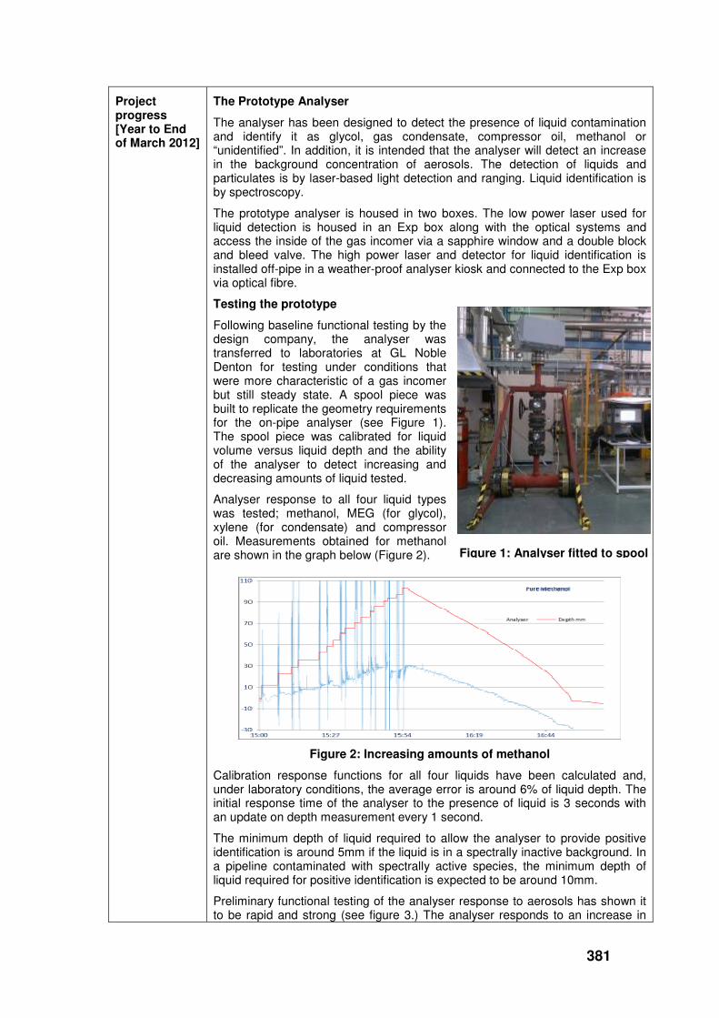
381
Project progress [Year to End of March 2012]
The Prototype Analyser
The analyser has been designed to detect the presence of liquid contamination and identify it as glycol, gas condensate, compressor oil, methanol or “unidentified”. In addition, it is intended that the analyser will detect an increase in the background concentration of aerosols. The detection of liquids and particulates is by laser-based light detection and ranging. Liquid identification is by spectroscopy.
The prototype analyser is housed in two boxes. The low power laser used for liquid detection is housed in an Exp box along with the optical systems and access the inside of the gas incomer via a sapphire window and a double block and bleed valve. The high power laser and detector for liquid identification is installed off-pipe in a weather-proof analyser kiosk and connected to the Exp box via optical fibre.
Testing the prototype
Following baseline functional testing by the design company, the analyser was transferred to laboratories at GL Noble Denton for testing under conditions that were more characteristic of a gas incomer but still steady state. A spool piece was built to replicate the geometry requirements for the on-pipe analyser (see Figure 1). The spool piece was calibrated for liquid volume versus liquid depth and the ability of the analyser to detect increasing and decreasing amounts of liquid tested.
Analyser response to all four liquid types was tested; methanol, MEG (for glycol), xylene (for condensate) and compressor oil. Measurements obtained for methanol are shown in the graph below (Figure 2).
Figure 2: Increasing amounts of methanol
Calibration response functions for all four liquids have been calculated and, under laboratory conditions, the average error is around 6% of liquid depth. The initial response time of the analyser to the presence of liquid is 3 seconds with an update on depth measurement every 1 second.
The minimum depth of liquid required to allow the analyser to provide positive identification is around 5mm if the liquid is in a spectrally inactive background. In a pipeline contaminated with spectrally active species, the minimum depth of liquid required for positive identification is expected to be around 10mm.
Preliminary functional testing of the analyser response to aerosols has shown it to be rapid and strong (see figure 3.) The analyser responds to an increase in
Figure 1: Analyser fitted to spool

382
the background concentration of aerosols regardless of whether the aerosol is liquid or solid. Currently, National Grid cannot trap particulate contamination sized below 5µm and it would be very useful if the analyser could identify the presence of all particulate matter between 2 and 5µm. Further testing using 3µm particulates will be carried out when the analyser is tested on the high pressure test loop at GL’s Spadeadam Test Facility.
Collaborative partners
None.
R&D provider GL Noble Denton
Figure 3: Response to aerosol

383
Project title Development of FWACV Capability for New Gas Chromatograph DANINT Software
Project Engineer
Roger Wood
Description of project
This project will:
• Research, develop and trial the application of more accurate and reliable management of gas composition, calorific value (CV) and volume data at Ofgem-directed sites to enhance the performance of network.
• Implement Flow Weighted Average CV (FWACV) onto improved and next generation gas chromatographs via engineering software that complies with Ofgem regulatory requirement, 'The Gas Calculation of Thermal Energy Regulations'.
Expenditure for financial year
Internal £7k
External £12k
Total £19k
Expenditure in previous (IFI) financial years
Internal £5k
External £17k
Total £22k
Total project costs (collaborative + external + NG)
£52k Projected 2012/13 costs for NG
£11k
Technological area and/or issue addressed by project
This project provides an opportunity to improve the accuracy and reliability of data provision from these sites in line with regulatory requirements. Currently, National Grid Gas Transmission and the other four operators are operating Daniels Model 500 Process Gas Chromatographs on Ofgem-directed sites.
The project will research, develop and seek Ofgem approval of a methodology to be delivered in the next release of DANINT software, build 12c, that can interface with next generation (model 700) Daniels Process Gas Chromatographs and also for use with the Model 500 + New Processor card. (Note that National Grid are currently using build 12a software, so additional £5.6k is required to first upgrade to build 12b software)
The broad project aims are to:
• Develop a system solution through information gathering with the supplier of the Ofgem approved analyser
• Develop processes to collect data from the Approved CV analyser and flow computer that can be incorporated into DANINT software.
• Develop the methodology for creation of secure data files that will be used in the calculation of FWACV.
• Support the application to Ofgem for the approval of the software changes, following trials on FWACV system.
Project Benefits Rating
Project Residual Risk
Overall Project Score
Type(s) of innovation involved
Incremental
8 -8 16

384
Expected benefits of project
This project provides an opportunity to enhance network performance through improving the accuracy and reliability of data provision, in line with regulatory requirements. Environmental benefits are also achieved through the reduction in transport associated with site visits and the reduced use of bottled helium gas.
If the improvements are successful, there is also an opportunity to reduce operational costs, as the improved system is rolled out onto National Grid’s FWACV sites.
A typical FWACV site consumes bottled helium gas and requires a bottle change approximately once every 8 weeks. This is a one-day job requiring two members of staff on site. A typical visit costs £545 (£500 in labour and £45 for 1 bottle of Helium) and each site will require 6 visits or costs of £3,270 per year.
If the project is successful, the number of site visits per year is expected to reduce from 6 to 2, resulting in an annual saving of £2,180 per implementation.
The implementation programme is yet to be finalised for National Grid Transmission. However, for the purposes of project justification, we can assume that two sites will be converted per year over the next five years, starting next year.
Expected timescale of project
5 years Duration of benefit once achieved
5 years
Probability of success
80% Project NPV = (PV benefits – PV costs) x probability of success
£11k
Potential for achieving expected benefits
Benefits will be realised with the provision that the new version/equipment is deployed by each funding party. The main benefits expected from the project to date are an operational efficiency saving per site where deployed and compliance with Ofgem approved equipment.
Project progress
[Year to End of March 2012]
Testing and development has been undertaken of the following systems:
1. Ofgem approved DANINT FWACV software. Tested over multiple scenario for use with the Daniel Model 700 gas chromatograph and 2350 (new card) Controller.
2. EOD software. Version 5.3 of EOD was developed to use the difference in the Offtake Cumulative Volume Tota” between consecutive DAT file records. The output included the demonstrating and testing of these revisions, and presenting the results back to Ofgem for approval.
3. The new version of DANINT. Installation of DANINT took place at the National Grid Gas Distribution’s Holford site. Several issues occurred following install, however, they have not been directly attributed to the system. Based on these findings, further revision is necessary.

385
Collaborative partners
Leverage of 5:1 on the IFI costs:
• National Grid Gas Distribution – 20% (Project Lead)
• Northern Gas Networks – 20%
• Scotia Gas Networks – 20%
• Wales & West Utilities – 20%
• National Grid Gas Transmission – 20%
R&D provider GL Noble Denton

386
Capacity & Capability
Project title Combined Geophysics Tool for Pipelines Routeing & Risk Assessment
Project Engineer
Matthew Sumerling
Description of project
The project objective is to trial new approaches to subsurface (geophysical) surveying, which will reduce the cost of pipeline construction projects caused by unforeseen or avoidable sub-surface ground conditions. This project will trial these new approaches on two construction projects to cover all areas of the research and prove the technologies fit for purpose.
It is hoped that this project will provide a cost effective method to give detailed geological information prior to beginning site works on construction projects and allow for the optimum route to be found.
Expenditure for financial year
Internal £5k
External £46k
Total £51k
Expenditure in previous (IFI) financial years
Internal £16k
External £349k
Total £365k
Total project costs (collaborative + external + NG)
£426k Projected 2012/13 costs for NG
£10k
Technological area and/or issue addressed by project
The issue addressed is how best to combine the multitude of geophysical techniques on one platform meaning that one survey will provide the majority of information required for construction projects. Although the technologies are existing, using a multisensory platform has not been done before in the UK energy sector. The research will examine the benefits of greater integration of geophysical data into the pipeline routing process at an earlier stage of project design.
Project Benefits Rating
Project Residual Risk
Overall Project Score
Type(s) of innovation involved
Technology Transfer
14 1 13
Expected benefits of project
Cost savings of 5:1 are claimed for the use of a mobile multi-sensor platform, compared to traditional subsurface survey methods (saving on costs of liaising with landlords and matching up disparate datasets from individual specialists). It is claimed that a corridor 2.5km x 40m could be surveyed each day with the mobile multisensory platform. By undertaking subsurface surveys of the soil composition before and after a pipeline is laid, National Grid has the data available to deal with (e.g. counter) any compensation claims from the landlord that the soil composition (i.e. soil type and %clay) has been changed.
The development of a best practice manual, decision support tool and survey data visualisation will help to ensure that the above benefits are available for future pipeline construction projects.
Expected timescale of project
3 years
Duration of benefit once achieved
Lifetime of inserted pipes

387
Probability of success
60% Project NPV = (PV benefits – PV costs) x probability of success
£3,669k
Potential for achieving expected benefits
Phase 1: The potential for achieving the expected benefits remains high for the Route Corridor selection despite issues surrounding land access which increased the costs and prevented access to all sections of all routes. The method of integrating the geophysical findings with the environmental study findings needs to be reviewed and refined to gain maximum benefit.
Phase 2: The potential for achieving the expected benefits remains high despite some issues with the equipment being very sensitive and picking up unwanted interference from the surroundings. Cost-benefit analysis will need to be carried out to determine the level of sensitivity required. The benefits will only be able to be assessed following the post-construction survey.
Project progress [Year to End of March 2012]
Phase 1 of the Hornsea-Beeford Geophysical survey works is complete and the draft Phase 1 report has been delivered. It has been reviewed within National Grid and discussions are ongoing to finalise how the route selection criteria adopted by Zetica to ensure the method of integrating the geophysical findings with the environmental study findings is sufficiently refined to gain maximum benefit.
Phase 2 of the works has been initiated. Pre-Construction Surveys have taken place on the Hole House Farm Pipeline construction project and the results received and analysed. The pipeline was reinstated in September/October 2011 and Post-Construction surveys will take place on the pipeline route once land access has been granted.
The Best Practice Manual is being completed following the conclusion of physical works to ensure all lessons learned could be included.
Collaborative partners
None
R&D provider Zetica

388
Environment
Operational Venting
Project title Alternatives to Venting from the NTS Gas Transmission System
Project Engineer
Ian Briggs
Description of project
The key objective of this study is to develop practical methods to reduce the emissions of methane that would otherwise occur during venting to the atmosphere from the natural gas transmission network.
Expenditure for financial year
Internal £10k
External £677k
Total £687k
Expenditure in previous (IFI) financial years
Internal £18k
External £394k
Total £413k
Total project costs (collaborative + external + NG)
£1,150k Projected 2012/13 costs for NG
£51k
Technological area and/or issue addressed by project
Natural gas, which is typically 85-93% methane, is released to the environment from gas transmission networks in a number of ways, including:
Infrastructure containment failures (e.g. elastomer seals, small bore pipework connections, pipework failures)
• Operational venting for decommission/repair or extension of networks
• Process venting from equipment (planned and unplanned)
• Fugitive leakage from pipeline equipment
Venting and fugitive leakage constitutes a significant part of the overall methane losses to atmosphere. Fugitive leakage from the NTS has been estimated to be of the order of 4000 tonnes per annum. Although this project will not address fugitive emissions, the figure is given here to compare with operational venting of methane (i.e. planned venting for maintenance or automated venting of compressor units during emergency shutdowns).
Planned venting can arise from a number of sources around the network, including venting at compressor sites and pipeline decommissioning prior to repairs, replacement or modification activity.
Planned venting at compressor sites is monitored and recorded through the on-line control system. For 2007, NTS reported to the Environment Agencies that there had been 1887 tonnes of natural gas emitted by planned vented from compressor stations.
Pipeline pressure is typically reduced to 7barg by recompressing it into an adjacent pipeline. However, the last 7barg can not be sensibly recompressed using the available equipment. It is therefore safely vented to atmosphere. Historical trends suggest that in excess of 150,000m
3 of pipework volume is
vented to atmosphere in this way each year (about 1000 tonnes of gas).
Clearly there are sound environmental and energy efficiency reasons for developing methods to reduce the amount of vented natural gas. There are several points that influence the current venting best practice, including both commercial and operational factors in addition to energy saving and environmental concerns. These concerns include the consideration of:
Distance between pipeline block valves. These isolation distances are tending to
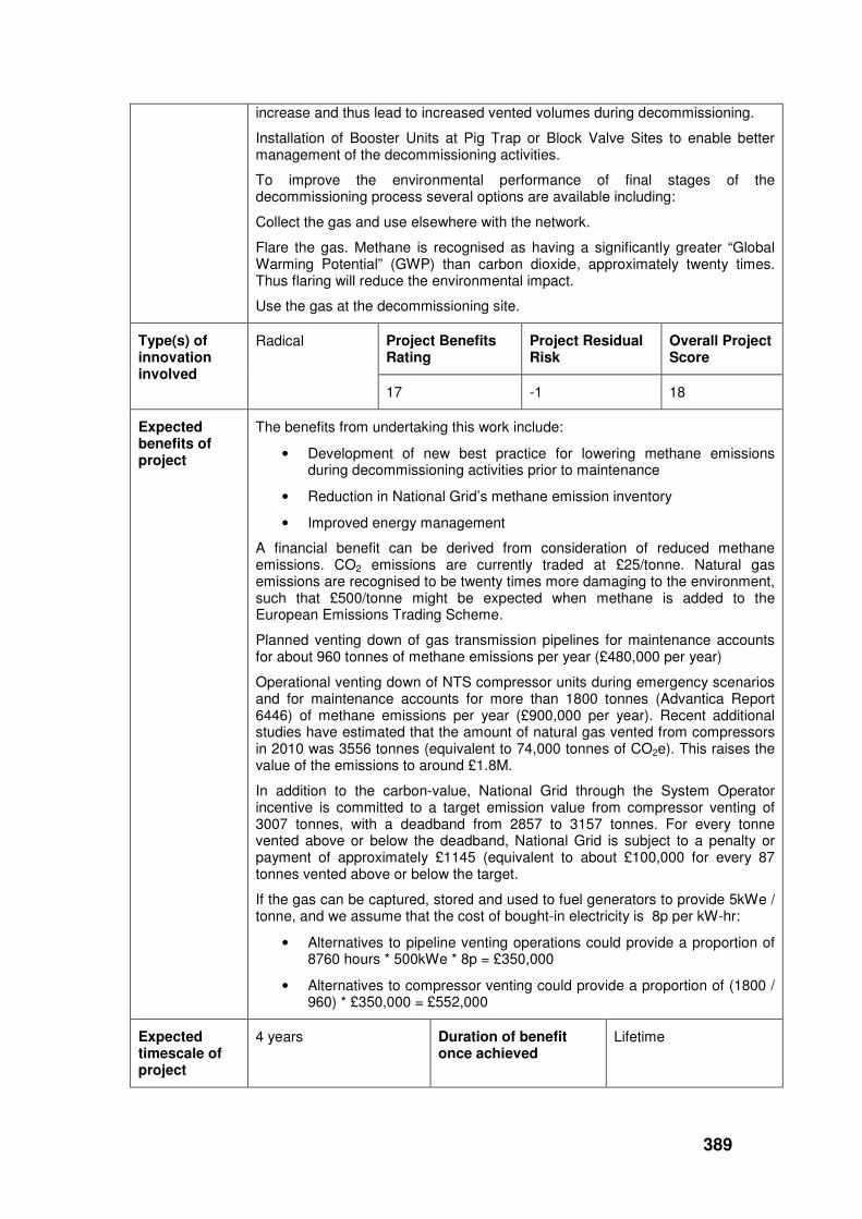
389
increase and thus lead to increased vented volumes during decommissioning.
Installation of Booster Units at Pig Trap or Block Valve Sites to enable better management of the decommissioning activities.
To improve the environmental performance of final stages of the decommissioning process several options are available including:
Collect the gas and use elsewhere with the network.
Flare the gas. Methane is recognised as having a significantly greater “Global Warming Potential” (GWP) than carbon dioxide, approximately twenty times. Thus flaring will reduce the environmental impact.
Use the gas at the decommissioning site.
Project Benefits Rating
Project Residual Risk
Overall Project Score
Type(s) of innovation involved
Radical
17 -1 18
Expected benefits of project
The benefits from undertaking this work include:
• Development of new best practice for lowering methane emissions during decommissioning activities prior to maintenance
• Reduction in National Grid’s methane emission inventory
• Improved energy management
A financial benefit can be derived from consideration of reduced methane emissions. CO2 emissions are currently traded at £25/tonne. Natural gas emissions are recognised to be twenty times more damaging to the environment, such that £500/tonne might be expected when methane is added to the European Emissions Trading Scheme.
Planned venting down of gas transmission pipelines for maintenance accounts for about 960 tonnes of methane emissions per year (£480,000 per year)
Operational venting down of NTS compressor units during emergency scenarios and for maintenance accounts for more than 1800 tonnes (Advantica Report 6446) of methane emissions per year (£900,000 per year). Recent additional studies have estimated that the amount of natural gas vented from compressors in 2010 was 3556 tonnes (equivalent to 74,000 tonnes of CO2e). This raises the value of the emissions to around £1.8M.
In addition to the carbon-value, National Grid through the System Operator incentive is committed to a target emission value from compressor venting of 3007 tonnes, with a deadband from 2857 to 3157 tonnes. For every tonne vented above or below the deadband, National Grid is subject to a penalty or payment of approximately £1145 (equivalent to about £100,000 for every 87 tonnes vented above or below the target.
If the gas can be captured, stored and used to fuel generators to provide 5kWe / tonne, and we assume that the cost of bought-in electricity is 8p per kW-hr:
• Alternatives to pipeline venting operations could provide a proportion of 8760 hours * 500kWe * 8p = £350,000
• Alternatives to compressor venting could provide a proportion of (1800 / 960) * £350,000 = £552,000
Expected timescale of project
4 years Duration of benefit once achieved
Lifetime

390
Probability of success
60%
Project NPV = (PV benefits – PV costs) x probability of success
£48k
Potential for achieving expected benefits
The financial and environmental benefits that this project can bring are still evident, in that substantial natural gas emissions savings can be made through reduced venting of gas. The continued laboratory test work has confirmed the gas capture capability. The design activities have shown that the process is both practical and realisable.
The development of the Decision Support Tool has enabled better estimates to be made of the overall benefit of reduced venting, encompassing gas capture, flaring and recompression
To achieve the proposed benefits will require implementation of the developed technology and additional activities with regard to the Policy and Procedures related to venting either from pipelines or compressor sites.
Project progress [Year to End of March 2012]
After the successful completion of the initial technical and economic feasibility phases of the project, the focus has been on developing the overall natural gas capture process to a stage of half-scale demonstration and testing.
The feasibility study and laboratory scale demonstration of adsorbed natural gas (ANG) storage highlighted the potential benefits of this technology on compressor stations. Gas that would otherwise be vented following compressor unit shut-down can be stored and re-used for other site operations.
Mechanical, electrical and Instrumentation designs have been completed to meet the practical, process requirements for National Grid and for installation on a high-pressure gas transmission site.
Civil works and mechanical construction have been completed, The ANG vessel and guard bed vessel were filled with activated carbon using a vacuum conveying method at the Spadeadam test facility as shown in the image on the right.
The filled ANG vessel is now installed in the gas test facility built at GL’s Bishop Auckland Flow Centre test site. The vessel forms the key part of the facility that also includes the guard bed, heaters, compressors, and the gas quality measurement equipment.
In parallel with the civil and mechanical work, the Electrical and Instrumentation design development has been undertaken, and extensive measurement and telemetry used to ensure detailed control and data logging is possible. The parametric testing to be undertaken will provide information on the overall process and enable optimisation of the system to improve the operational performance.

391
Simulation diagram of the ANG vessel
A mimic layout of the test rig has been developed to assist in data capture and process control. The mimic layout forms a key part of the Human Machine Interface (HMI). This aspect is undergoing further development to ensure that the system is fit-for-purpose for replication on a real, operational site.
Plant overview – mimic layout
The Decision Support Spreadsheet has been produced to quantify the vented amount of natural gas, estimate the cost-benefit by reducing the amount vented and provide guidance on the possible best options to reduce the overall emissions.
The Decision Support Spreadsheet can be used for a number gas industry operations including Compressor venting, venting from Pipeline maintenance and repair, and venting from smaller-scale activities like PIG trap or filter maintenance. It highlights the potential emission avoided through use of different technologies and enables users to assess the best options for specific sites or operations.
A wider use of the Decision Support Spreadsheet is currently under review.
Collaborative partners
None
R&D provider GL Noble Denton

392
Project title Environmental Study for Future Above Ground Facility Developments
Project Engineer
Neil Dawson
Description of project
This project aims to identify what needs to be considered (in 2009 and the next 7-years) during the design of above ground installations (i.e. offtakes, multi-junctions, block valve sites and compressor facilities) if the design objective is changed from simple least cost to pursue an ambition to create the least environmentally damaging facility possible.
The second objective is then to identify the relative costs and applicability of each design option so that conclusions can be drawn about the best available techniques (from an environmental and cost perspective) that should be applied over the medium term.
Expenditure for financial year
Internal £5k
External £15k
Total £20k
Expenditure in previous (IFI) financial years
Internal £7
External £139
Total £145
Total project costs (collaborative + external + NG)
£165k Projected 2012/13 costs for NG
£0
Technological area and/or issue addressed by project
A major source of planning delay has been objections that relate to the environmental impact of our proposed developments. In order to respond to such challenges National Grid needs to be able to discuss the merits of technologies that may have been rejected as well as those that are actually utilised. This type of information is not available to National Grid at present and represents a significant risk National Grid in the planning process.
Project Benefits Rating
Project Residual Risk
Overall Project Score
Type(s) of innovation involved
Significant
7 4 3
Expected benefits of project
The results of this piece of work will be used by National Grid to:
• Support future planning applications for all above ground facilities, with complexity up to and including gas compressor stations. It will provide evidence of extensive research undertaken to specify the minimum range of innovative options that were required to be considered during project-specific environmental BAT studies.
• Where appropriate, rewrite its policies for design of gas installations.
• Reduce the delays associated with addressing public concerns over the environmental impact of a new facility, by being proactive and having suitable information in advance of potential projects (and the ensuing objections).
• Be able to reinforce and enhance their reputation with the general public and other stakeholders, as a good steward of the environment, because it will be seen to be proactively managing, and seeking to reduce, its impact on the environment.

393
Expected timescale of project
2 years Duration of benefit once achieved
5 years
Probability of success
70% Project NPV = (PV benefits – PV costs) x probability of success
£131k
Potential for achieving expected benefits
This project has three key deliverables which are all essentially stand alone reports. Each deliverable will be discussed individually within this document.
Pre-BAT Assessment of Gas Compression
Examination of the current best available techniques for gas compression whilst considering current and forthcoming environmental legislation. The report explores the two key scenarios for the gas transmission network going forward - New Build and Air Quality Improvements on Legacy Gas Turbines - taking into account the added flexibility required for a changing network.
For the New Build scenario the report recommends that environmental savings can be made by generating electricity on site using gas engines when compared to the carbon dioxide produced from the current UK electricity grid. This local electricity generation can then be used to power variable speed electric drives (VSD) which exhibit good efficiency across the power range.
Inside a gas engine power plant (Wärtsilä)
For the Air Quality Improvements on Legacy Gas Turbines scenario the report explores air quality abatement retrofit techniques to allow existing sites to meet the challenging emission limits outlined in the new EU Industrial Emissions Directive.
The report also considers post combustion carbon sequestration but concludes that due to the infrequent use and low volumes of CO2 emitted, this would be impractical. It is expected this pre-BAT study will form the basis of the Gas Network Investment strategy going forward and will provide a template for BAT studies on a site by site basis.
Use of Services
Environmental improvements for future above ground facilities (AGF’s) is currently being used to challenge the off the shelf design approach previously adopted by construction contractors. This part of the project is split into 16 separate environmental improvements with each demonstrating the quantifiable benefits of adopting them at both existing and new sites. The document has

394
formed a key part of the design strategy for new build sites and is expected to be added to tender ‘minimum requirements’ standards. The improvements have also been posted on the National Grid intranet.
Building Materials
Consideration of low carbon building materials for construction of future above ground facilities. This includes recycled and reclaimed materials alongside new construction materials with low embodied carbon. Where possible, worked examples have been provided quantifying the benefits of adopting alternative materials at sites.
The report concludes that a high percentage of the embodied carbon of a product is attributed to the transport of the materials to site and therefore locally sourced materials have an environmental benefit. On average, adopting higher recycled content materials reduces the overall environmental impact of a construction project, however, any carbon associated with the processing of these materials should also be considered. The portfolio has already been adopted as guidance for construction projects and has been uploaded onto the National Grid intranet.
Project progress [Year to End of March 2012]
There are 49 improvements identified for future above ground facilities developed in Phase I of this project. They are categorised into three areas:
1. Architectural
2. Use of Services
3. Building Materials
After consultation it was decided that National Grid already had a good handle on the architectural aspects of new above ground facilities and so this area was not considered further. Due to changes in the gas transmission network strategy going forward since Phase I, it was decided to instead carry out a pre-BAT assessment of the primary drivers of gas compression.
Pre-BAT Assessment of Gas Compression
The project team researched exhaustively the possibilities for providing gas compression and evaluated them against new and existing environmental legislation. Two scenarios were considered:
1. New Build
2. Air Quality Improvements on Legacy Gas Turbines.
The options included use of gas engines to generate electricity locally on site followed by VSD electric drives for new builds and retrofitting emission abatement technologies to existing gas turbines.
Combined CO & NOx abatement systems (Johnson Matthey)
One of the key aspects of the report focussed on use of multiple turbines with different power ratings to improve running efficiencies across a wider operating range as illustrated below. GL Noble Denton presented a draft of the report during a workshop held in Loughborough on 24th February 2011.

395
Some of the pre-BAT study was used in the Network Review to illustrate to the competent authority that indicative BAT includes the scenario-based examples e.g. multiple units on new build.
Use of Services
Environmental improvements to the use of services at above ground facilities were researched, these included:
• Links Between Improvements
• Insulation Materials
• Use of Waste Heat
• Green Energy Accounts
• Solar Power and Wind Turbines
• Storage of Renewable Energy
• Power Optimisers
• Carbon Zero Air Compressors
• Maximisation of Natural Lighting
• Ground Source Heat Pumps
• Rainwater & Greywater Harvesting
• Sustainable Drainage Systems
• Fuel Gas Pre-Heating
• Venting & Leakage
• Trace Heating
• Gas Actuated Valves
• Fuel Cells
As part of the research the environmental and other benefits were quantified by evaluating them against existing available utility/site data. In addition, the project has investigated how these improvements can be linked to produce further environmental benefits, illustrated for 3 different scenarios:
1. Legacy Site Heat Recovery & Storage
2. Legacy Site Electricity Generation
3. New Build Heat & Power
Wind Turbine
Photovoltaic panels
Mains Supply
Gas Engine Generators
Electric Drive Compressors
Organic Rankine Cycle Generator Ground Source
Heat Pump
Solar Heating Panels
Vent/Leakage ANG Storage Gas
Gas Water Heating
Fuel Cell
Hot Water Storage
Battery Storage
Inverter
Heating: Office/Workshop Trace Heating Machinery Cabs Compressor Oil
Instrumentation & Control Lighting Office Equipment Air Compressors
Gas In
Discharge Gas Cooling
Electric Power
Exhaust Electric Power
Gas Out
Hot Water
Heat
Gas Electricity Use of Waste
Storage
Renewable
Fossil Fuels
End Use
Heat
Colour Key
Diagram for the New Build Heat & Power scenario.

396
Building Materials
A thorough review of alternative low carbon building materials including recycled and reclaimed goods was performed and the applicability of each type was evaluated for use at NG sites. This part of the project evaluates the embodied carbon of each material type and offers quantified examples of environmental benefits where possible. The range of materials documented include external construction materials like bricks, timber and steel through to internal furnishings such as carpet, plaster and paint.
The Building Materials portfolio was delivered by GL Noble Denton in February 2011
The project has highlighted manufacturer’s green wash, where claims of environmental benefits are not substantiated by evidence. It also looks at product developments which may hold future environmental benefits like negative carbon concrete. The importance of sourcing materials locally was focussed on and the depletion of natural resources was also considered as aspects of sustainable construction techniques.
Collaborative partners
None
R&D provider GL Noble Denton

397
Project title Bleed Reduction on Gas Chromatographs
Project Engineer
Neil Dawson
Description of project
The aim of this project is to:
• Confirm the emission rates
• Evaluate options to reduce the emissions
This will include oxidation of the gas to carbon dioxide, e.g. small-scale catalytic combustors. The project will also review alternative methods to provide sufficient transit speed, as appropriate.
Expenditure for financial year
Internal £5k
External £7k
Total £12k
Expenditure in previous (IFI) financial years
Internal £0
External £0
Total £0
Total project costs (collaborative + external + NG)
£12k Projected 2012/13 costs for NG
£0
Technological area and/or issue addressed by project
There are over 120 Danalysers (gas chromatographs) on the network. Currently, a continuous bleed of gas is used to speed up the transit time from the insertion probe to the gas chromatograph. A second, smaller bleed is then used to purge the gas chromatograph at a continuous rate.
This project will produce an options study for the potential reduction of natural gas emissions from gas chromatograph systems on NTS above ground facilities.
Project Benefits Rating
Project Residual Risk
Overall Project Score
Type(s) of innovation involved
Incremental
7 -4 11
Expected benefits of project
The business benefit is reduction in the amount of natural gas vented to atmosphere (currently around £1.25k per tonne). The overall target environmental benefit is to reduce the natural gas venting by over 50%. Outcome of the project may also facilitate further benefit from more responsive gas analysis.
Expected timescale of project
1 year Duration of benefit once achieved
Continuous
Probability of success
60% Project NPV = (PV benefits – PV costs) x probability of success-
-£4k
Potential for achieving expected benefits
Developments to the sampling equipment and overall process for gas analysis can potentially result in emissions reduction to meet the target. As well as improving the response times for the analysis equipment. A programme to retro-fit equipment has started and the data obtained to date confirms the predicted project benefits.
Project The project has focused on several themes:
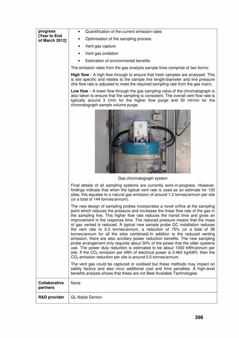
398
progress [Year to End of March 2012]
• Quantification of the current emission rates
• Optimisation of the sampling process
• Vent gas capture
• Vent gas oxidation
• Estimation of environmental benefits
The emission rates from the gas analysis sample lines comprise of two forms:
High flow - A high flow through to ensure that fresh samples are analysed. This is site specific and relates to the sample line length/diameter and line pressure (the flow rate is adjusted to meet the required sampling rate from the gas main).
Low flow – A lower flow through the gas sampling valve of the chromatograph is also taken to ensure that the sampling is consistent. The overall vent flow rate is typically around 3 l/min for the higher flow purge and 30 ml/min for the chromatograph sample volume purge.
Gas chromatograph system
Final details of all sampling systems are currently work-in-progress. However, findings indicate that when the typical vent rate is used as an estimate for 120 sites, this equates to a natural gas emission of around 1.2 tonnes/annum per site (or a total of 144 tonnes/annum).
The new design of sampling probes incorporates a novel orifice at the sampling point which reduces the pressure and increases the linear flow rate of the gas in the sampling line. This higher flow rate reduces the transit time and gives an improvement in the response time. The reduced pressure means that the mass of gas vented is reduced. A typical new sample probe GC installation reduces the vent rate to 0.3 tonnes/annum, a reduction of 75% (or a total of 36 tonnes/annum for all the sites combined).In addition to the reduced venting emission, there are also ancillary power reduction benefits. The new sampling probe arrangement only requires about 30% of the power that the older systems use. The power duty reduction is estimated to be about 1000 kWh/annum per site. If the CO2 emission per kWh of electrical power is 0.463 kg/kWh, then the CO2 emission reduction per site is around 0.5 tonnes/annum.
The vent gas could be captured or oxidised but these methods may impact on safety factors and also incur additional cost and time penalties. A high-level benefits analysis shows that these are not Best Available Technologies.
Collaborative partners
None
R&D provider GL Noble Denton

399
Customer Satisfaction & Commercial
Charging Frameworks
Project title Daily Gas Demand Forecasting
Project Engineer
Chris Aldridge
Description of project
The main aim of the project is to develop new methods for forecasting the daily gas demand from the National Transmission System. These would be used to improve the demand forecasts that are provided to the market and used in operational decision-making.
Expenditure for financial year
Internal £7k
External £101k
Total £108k
Expenditure in previous (IFI) financial years
Internal £0
External £0
Total £0
Total project costs
(collaborative + external + NG)
£117k Projected 2012/13 costs for NG
£9k
Technological area and/or issue addressed by project
National Grid Transmission forecasts the national gas demand for each day over a range of timescales, from a week ahead to within the day, and publishes forecasts to the gas market. This includes the demand from distribution networks, power stations, industrial loads, storage sites and interconnectors.
Current systems calculate demand forecasts using a “bottom-up” approach, by combining forecasts for individual elements, using regression techniques. The model is complicated and the results are unreliable. An extra forecast is done day ahead using a spreadsheet model largely based on a “top-down” forecast of the total demand, also using regression, which gives a more accurate prediction. These are used as the basis for the forecasts published and used by the Gas National Control Room.
The proposed project would investigate using local predictor techniques, which automatically identify similar days in history to the forecast day, to make a top-down forecast of total demand. This is a different approach to the fixed regression formula currently used, and initial tests have indicated a significant increase in accuracy over the current models.
Project Benefits Rating
Project Residual Risk
Overall Project Score
Type(s) of innovation involved
Technical Transfer
13 -4 17
Expected benefits of project
National Grid’s published demand forecasts ahead of the day are used by the market to aid trading and operational decisions in balancing supply and demand on the day. This work is likely to lead to better information provided to National Grid’s customers in the gas industry, and potentially reduces gas price distortions.
Expected timescale of project
1 year Duration of benefit once achieved
5 years

400
Probability of success
60%
Project NPV = (PV benefits – PV costs) x probability of success
£1,069k
Potential for achieving expected benefits
There is a good potential that the benefits will be realised. The worth of the new techniques has been proved, and provided knowledge transfer is made and the prototype tool implemented, the benefits can be achieved.
Project progress
[Year to End of March 2012]
Since this project started in July 2011 an initial local predictor model was created for day-ahead demand forecasting, based around weather data, and tested over a historical period. As predicted, this model shows improved accuracy over current methods.
Live Trails
The model was then refined and a system was set up launch a live trial in October 2011. The live trial is running the model every day to prove the worth of the new techniques. Results to date have once again demonstrated better accuracy than current methods being used by the business. Work on the live trial continues.
Trailing new methods of forecasting the daily gas demands from the NTS
Additional Trials
Additional trials are underway to understand model accuracy based on alternative inputs. Liverpool University has investigated improving the model using gas prices as an input. Initial results using historical data indicated a further improvement in accuracy.
Collaborative partners
None
R&D provider Liverpool University

401
Information Provision
Project title Automatic Risk-Based Handling Of Plant Enquiries
Project Engineer
Nik Wileman
Description of project
Development and trial of an automated web-based response service to advise developers of construction restrictions in the vicinity of National Grid energy transmission assets.
Expenditure for financial year
Internal £5k
External £21k
Total £26k
Expenditure in previous (IFI) financial years
Internal £29k
External £82k
Total £111k
Total project costs (collaborative + external + NG)
£193k Projected 2012/13 costs for NG
£55k
Technological area and/or issue addressed by project
This project is evaluation whether the risk of third party interference can be reduced by automatic handling of developers’ enquiries relating to critical National Grid assets. Such interference can have consequences for security of energy supply, public safety and the environment, together with the associated operational coasts and cost from potential prosecution and/or damages claims.
Interference damage from third party developers, causing a London black-out, is a credible and potentially costly incident. Having a system that gives instant, repeatable, reliable responses to those third parties (including utilities, contractors and local government) involved in development work in the vicinity of National Grid assets should reduce the risk of interference damage.
Third part interference causing environmental damage is also a credible possibility. Methane released from gas pipelines is 20 times more damaging than carbon dioxide. Oil releases from electrical cables can lead to the risk of prosecution, especially if not discovered by National Grid at the time of damage.
Project Benefits Rating
Project Residual Risk
Overall Project Score
Type(s) of innovation involved
Incremental
13 4 9
Expected benefits of project
The proposed system is designed to mitigate the risk of third party damage. This system will provide comprehensive, accurate and timely asset information and advice based on agreed plant protection rules. Known areas of critical supply and priority/vulnerable customers can be defined in the system and monitored for high risk works. Notification emails can be triggered to plant protection engineers when enquires are received matching criteria setup in the system, such as the examples listed above or when monitoring named users/ organisations that may be causing frequent damage or near misses.
National Grid Transmission Land and Development currently handle plant location enquiries form external organisations on a manual basis, utilising a team of about 7 fulltime employees. With an automated response service in place, this team could focus more time on any exceptions, for example the more difficult enquiries, as well as conducing quality assurance and identifying potential improvements to the automated response service.

402
Expected timescale of project
5 years Duration of benefit once achieved
5 years
Probability of success
80%
Project NPV = (PV benefits – PV costs) x probability of success
£44k
Potential for achieving expected benefits
Confidence that the project will realise the intended benefits continues to be high based on positive feedback from the completion of external (third-party) and internal (National Grid Plant Protection team) trials of the system.
Project progress [Year to End of March 2012]
A pilot of the self-service system was successfully trailed by third parties during stage 3 of the project. Outputs from the trail indicated that the system delivered usability, efficiency, and safety improvements in keeping with expectations. These were attributed to updates implemented to the rule and responses and the location functionality that served to improve overall efficiently and accuracy of the system.
Stage 4 of the project consisted of extended internal trials focused on:
• A proof of concept for the use of the Ordinance Survey OnDemand service in place of Google Maps.
• Integration of new OS technology for map mark-up and location search into the trail system.
The aim has been to test the feasibility of the above mentioned functionality and to gather additional feedback from expert users during user acceptance testing (UAT). As a result, a number of enhancements were identified based on UAT feedback that will further improve the system’s usability and enquiry management capabilities. These results will provide the foundations for a proposed production implementation of the self-service system during stage 5 of the project. The proposed deliverables in stage 5 have been defined and are set to run in parallel with a number of business critical enhancements.
Collaborative partners
National Grid Gas Distribution, National Grid Electricity Transmission.
R&D provider GL Industrial Services (UK) Ltd.
403
Strategic
New Material & Technology
Project title Research into Requirements for Gaseous Phase CO2 Transmission
Project Engineer
Russell Cooper
Description of project
National Grid is considering the change of use of existing natural gas National Transmission System (NTS) transmission pipelines so that they can be capable of transporting anthropogenic Carbon Dioxide (CO2) from large industrial emitters, such as power stations, to a location where the CO2 can be safely stored. This will require full demonstration, through preparation of a safety justification that the activity can be carried out safely.
The project involves a range of research and development activities to be undertaken in order that a robust safety justification for the design and operation of gaseous phase CO2 pipelines can be prepared.
Expenditure for financial year
Internal £16k
External £428k
Total £445k
Expenditure in previous (IFI) financial years
Internal £58k
External £1,771k
Total £1,830k
Total project costs (collaborative + external + NG)
£2,725k Projected 2012/13 costs for NG
£469k
Technological area and/or issue addressed by project
CO2 poses potential safety risks to people and the complex phase characteristics of the fluid require specialist modelling to assess the hydraulic behaviour on pipeline design and operation.
The nature of pure CO2 changes from gaseous condition to a dense phase condition at the critical point. In the gaseous phase, CO2 behaves as a heavy gas, but in the dense phase, the “fluid” has the viscosity of a gas and the density of a liquid. While transportation of dense phase CO2 offers efficiencies due to the properties of the fluid, National Grid’s immediate interests are in the transportation of gaseous phase CO2.
The heavy gas behaviour of the gaseous phase CO2 affects the dispersion of the gas and therefore the distances over which it disperses pose a hazard to people. Anthropogenic CO2 contains impurities, and the effects of these impurities on the phase boundary, hydraulic behaviour, hazard distance and pipe integrity need to be investigated and understood in order that pipeline design and pipeline operation can be carried out safely.
Project Benefits Rating
Project Residual Risk
Overall Project Score
Type(s) of innovation involved
Radical
19 5 14
Expected benefits of project
This research provides a benefit to gas consumers as it enables CO2 networks to be developed through the reuse of existing natural gas pipeline assets. This change of use will enable natural gas consumers to be protected against the decommissioning costs and associated liabilities that would otherwise be required if a natural gas pipeline is no longer required for natural gas transmission. Further value can be captured for gas consumers by reusing existing pipelines for other applications. The value in question may well be underpinned by calculations of residual asset value.
Wider energy consumers, including electricity consumers, stand to benefit if the research enables the development of CO2 networks to support carbon capture from coal fired generators. It is possible that without this technology there will be a much diminished role for coal in the UK energy mix, leading potentially to higher electricity prices and an impaired outlook for electricity security of supply.
Consumers will also benefit from the clear environmental benefits that will be delivered to the UK through effective mitigation of CO2 emissions. The UK Government and European Union both believe that Carbon Capture and Storage (CCS) present an important opportunity for reducing CO2 emissions. This research can be aligned with the environmental policies of both national and supra-national bodies, potentially presenting real opportunities to re-deploy existing natural gas assets efficiently in the service of mitigating climate change.
Expected timescale of project
5 years Duration of benefit once achieved
Lifetime
Probability of success
30%
Project NPV = (PV benefits – PV costs) x probability of success
£2,816k
Potential for achieving expected benefits
Benefit potentials remain good:
CO2 transportation through pipelines has been in operation in the United States since the 1970’s. These activities have been mainly focussed on the transport of naturally occurring CO2 from the source to various oil fields for the purposes of delivering Enhanced Oil Recovery (EOR). It is noted though that the CO2 pipelines in the United States are laid in remote areas and very little research work has been carried out relating to the safety aspects of pipeline operation. However, the knowledge that these pipelines exist and have been in operation for a substantial period of time provides a high degree of confidence that a successful CO2 transportation network can be developed in Europe.
Similar research and development (R&D) work was carried out for natural gas in the 1970s and 1980s and forms the basis of the safety justification for National Grid’s high pressure transmission network. The results of the work are not directly relevant to the transportation of CO2, but the logic applied and learning obtained will be applied as appropriate which assists in minimising timescales by the application of “lessons learnt”.
National Grid is utilising a range of service providers who have a wealth of experience with this type of R&D work and knowledge of CO2 systems.
Progress to date has been good for the R&D work and National Grid continues to monitor and review the R&D programme.

404
Project progress [Year to End of March 2011]
Overview
Research and Development (R&D) work conducted for gaseous phase Carbon Dioxide (CO2) covered four main work areas:
1. Corrosion testing utilising gaseous phase CO2.
2. Venting of gaseous phase CO2.
3. Dispersion of gaseous phase CO2 from craters.
4. Metering.
Details of each of these areas are outlined in the following pages.
1. Corrosion testing
MACAW Engineering Limited have previously conducted a series of tests for National Grid to assess the corrosion potential of transporting anthropogenic CO2 gas mixtures from industrial emitters in carbon steel pipelines.
The current work expands and develops the test work previously conducted and has the objective of assessing potential corrosion rates in conventional pipeline materials which could result from an unintentional release of water into a pipeline transporting gaseous phase anthropogenic CO2.
Work is split into the following four main tasks:
Task 1 - Modify the existing test rig to demonstrate the corrosion rates obtained in test work conducted by MACAW’s correlate with published test results.
Task 2 - Conduct a literature review of all available published data on corrosion in CO2 pipelines.
Task 3 - Using a gas mix derived from the National Grid worst case specification, investigate the corrosion mechanisms and rates over short durations using different linepipe materials.
Task 4 - An additional test matrix similar to task three including further testing which will be performed only if required and could test new operational scenarios, different gas mixes and/or alternate pipe material as required by the findings of task three.
Further information on each task is outlined in detail below.
Corrosion testing - Task 1
The objective is to demonstrate that the MACAW test facility can replicate the results of published data. In particular, the tests carried out by Yoon-Seok Choi

405
and Srdjan Nesic in their paper “Determining the corrosive potential of CO2 transport pipeline in high pressure CO2 water environments”.
Figures 1 and 2 show photographs taken during completion of this task.
Figure 2: Corrosion test weight loss coupon prior to testing
Task 1 has been completed and concluded:
• MACAW Engineering’s test rig produces results similar to those published by Choi and Nesic. However, it is not possible to replicate the results exactly, due to the published papers not providing details of all the test parameters. (Noting that most published data in this area do not fully detail the test parameters. As a result, it is difficult to replicate the results of experimental work precisely.)
• The tests also confirmed that higher corrosion rates were observed in the CO2 saturated water solution than in the water saturated gaseous CO2 phase.
Corrosion testing - Task 2
The review considered published papers, conference proceedings and relevant standards. The review also discussed how published data compared with the testing which has already been conducted and advised on what further work is required to understand corrosion risks to pipelines from the transportation of anthropogenic CO2 in both the gaseous and dense phase.
The review considered experimental techniques used in published work when testing with CO2 and gave recommendations on what techniques are the most suitable for the purposes of assessing the corrosion in CO2 pipelines.
Task 2 has been completed and the literature review concluded:
• Negligible corrosion rates are expected in CO2 free of impurities as long as water remains dissolved in the CO2 fluid.
• In the presence of impurities water solubility in CO2 can be lowered and corrosion may occur.
• In high pressure CO2 environments, it has been clearly confirmed that carbon steel materials exposed to free liquid water will suffer high sweet corrosion rates. However, there are clear discrepancies between the different corrosion rates reported and, equally significantly, the trend of corrosion rates with CO2 pressure has not been found to be consistent.

406
Confidence in data can only be achieved if the test procedure and parameters are clearly documented and sufficient tests are carried out to demonstrate repeatability.
• In the presence of impurities, corrosion in pipelines in the presence of an aqueous phase will be dependent on the types of impurities and their concentration in the CO2 stream and on the partitioning behaviour of these impurities between the different CO2 and water phases.
• Corrosion inhibitor injection could prove to be beneficial when water is present in the pipeline at high CO2 pressures but further testing is required.
• At high CO2 pressures, high grade stainless steels may be satisfactory for service, even in the presence of free liquid water at temperatures below 30 degrees Celsius. The effect of impurities remains to be tested.
Corrosion testing - Task 3
It is believed that the gas components that would have the greatest effect on corrosion were CO2, Nitrogen Dioxide (NO2) and Sulphur Dioxide (SO2). Therefore the following four test gas compositions are being considered and tested to evaluate their effects on the corrosion mechanisms:
1) Pure CO2.
2) CO2 + NO2.
3) CO2 + SO2.
4) CO2 + NO2 + SO2.
The corrosion mechanisms observed during the earlier test work showed sensitivity to the steel’s microstructure. So the testing includes three different types of materials to understand the effect that microstructure sensitive corrosion has on corrosion rates. The tests will be carried out on material from an existing high pressure natural gas pipeline (constructed circa 1975), material that is representative of a new section of pipeline and material from an existing older pipeline system (material from around the 1968 era).
Progress with Task 3 is advanced and will be completed shortly. Initial findings from the work completed so far are:
• Corrosion in the water saturated gaseous phase appears to be at a constant level.
• Corrosion rates decreased by up to 50% when the test conditions were changed from a pressure of 50 barg and 50 degrees Celsius down to 34 barg and 30 degrees Celsius.
• Small additions of NO2 appear to only have a small effect on corrosion rates.
• Small additions of SO2 appear to increase corrosion rates.
Corrosion testing - Task 4
This is additional test work (similar in nature to Task 3) to consider new operational scenarios, different gas mixes and/or alternate pipe material depending on the findings from Task 3.
2. Venting of gaseous phase CO2
As part of its research programme into the behaviour of CO2, National Grid commissioned a series of experiments to vent CO2 from storage to the atmosphere. In order to carry out the programme of work, two separate test facilities were constructed, one to examine a release at a steady rate through a vertically upwards pointing vent and the second to examine the gradual venting of a section of pipeline through a smaller diameter horizontal vent. The purposes of the experiments were to obtain data on the dispersion of the releases in the

407
atmosphere and to record the changing conditions in the CO2 vessel or pipeline during the venting process. The work carried out in this study examined the data collected during the experiments to seek out trends in the data and compared the behaviour of CO2 during the experiments with pragmatic models of the type used in carrying out risk assessments. This study has been completed.
In particular, the temperature, pressure and changes of phase that occurred as the CO2 depressurised on approach to the vent exit were examined and the outflow rate was compared with predictions. The measurements of the temperature within the first 5 meters of the atmospheric plume formed by the vertical vent were analysed and it was shown that a consistent set of data had been obtained, with the results following the expectations for a jet like flow. The trajectory of the plume was compared with the predictions of a dispersion model. It was noted in the experiments that, unlike some of the views that had been expressed prior to the experiments, no CO2 was observed to ‘rain out’ of the plume close to the source and in many of the experiments, the plume dispersed entirely whilst above ground level. The influence of wind speed and mass flow rate on trajectory was examined and it was noted that the concentrations that were recorded downwind of the release close to the ground were always below the level that would cause immediate harm to people. Interestingly, the experiments revealed large differences in behaviour were produced depending on whether the venting took place from the bottom or top of the length of horizontal pipework.
The information obtained should help in the safe design and conduct of any venting operations.
Reference is due to be made to the work in a paper to be presented at the 23rd Hazards international symposium being arranged by the Institution of Chemical Engineers (I.Chem.E.) in November 2012.
3. Dispersion of gaseous phase CO2 from craters
This work area incorporates a full scale puncture and rupture test using gaseous phase CO2. The puncture test was successfully completed on Friday 4th November 2011 although the rupture test can’t now be completed until late 2012/early 2013.
In order to reduce costs and minimise timescales, a test arrangement incorporated in another National Grid research programme is to be utilised although there is the potential for sequential delays. The other research programme has identified some significant technical issues that need to be urgently resolved which has identified a requirement to use the test rig to allow these to be investigated. So there is a consequent pro-rata delay in the subsequent programme of rupture tests to be undertaken.
Dispersion of gaseous phase CO2 from craters - Puncture test work
There have been many studies carried out to understand how a puncture of a buried natural gas transmission pipeline would behave. However, there is no similar, reported work on how a puncture in a gaseous phase CO2 pipeline would behave. Hence, an experiment was carried out at full scale in order to observe the behaviour and to collect data that would be of use in the development or validation of mathematical models for gas outflow and dispersion.
An existing section of buried, instrumented, 914 mm diameter pipeline was used to provide a source for the release. The pipeline was fitted with a 50.8 mm diameter bursting disk that was selected to fail when the pressure was raised above about 35 barg. The bursting disk was located in a horizontal position, on the side of the buried pipe, simulating a release from a puncture at this location. The pressure and temperature of the CO2 in the vessel were monitored, as was the temperature on the walls of the pipeline, especially close to the point of release. The release was allowed to form its own pathway through the surrounding soil to the surface. The dispersion in the atmosphere of the resulting CO2 cloud was monitored using an array of oxygen cells, located close to ground level in the nominal downwind

408
direction. Video records of the cloud that was formed were taken. In addition, temperature measurements were taken alongside the oxygen cells. The ambient wind speed and direction, atmospheric humidity and temperature were all logged during the experiment.
The observations showed that an open crater was not formed by this below ground release. Rather, the soil surface rose up slightly (up-welling) and the ground surface was cracked in numerous places. Evidence was found for a number of ‘blow holes’ in the soil, through which the CO2 flow made its way to the atmosphere. The equivalent free area of the blow holes was measured to be approximately 2.4m
2. The plume that was formed by the releases through the ‘blow
holes’ was observed to return to close to ground level and subsequently dispersed downwind under the influence of the wind. The maximum value of the recorded CO2 concentration, using 5 second moving averages, on each downwind arc has been plotted against the downwind and statistics on how the concentration varies with time have been obtained.
The experiment gave direct evidence of the importance at full scale of the source conditions, the density of the release in determining the dispersion behaviour and the results are currently being compared with the predictions of a number of mathematical models, to help improve the risk assessments for such releases.
Reference is due to be made to the work in a paper to be presented at the 23rd Hazards international symposium being arranged by the Institution of Chemical Engineers (I.Chem.E.) in November 2012.
4. Metering of CO2
Due to the unique properties and characteristics of CO2, it presents some challenges with regards to flow metering. National Grid has ascertained that there are still several knowledge gaps that need to be considered and investigated.
CO2 metering requires the same standards of uncertainty and error as natural gas applications but the challenges are very different - these include working at higher and lower pressures, avoiding the two phase regions of the phase diagram, using different sampling and analysis systems as well as different equations of state.
One approach is to construct a flow rig designed for CO2 operation in order to replicate an actual metering arrangement producing representative flow conditions which could be scaled up to develop our understanding of CO2 metering and confirm the primary flow metering principles whilst identifying any limitations. Two flow rig options have been considered and both have been found to be cost prohibitive.
National Grid then organised a tripartite meeting with TUV SUD NEL Ltd (NEL) and Germanischer Lloyd Noble Denton (GLND) in November 2011 to discuss and develop what other approaches/work could be undertaken to investigate CO2 metering to a level that will fill the knowledge gaps and confirm the primary flow metering principles.
NEL and GLND subsequently developed a joint proposal detailing a suggested work programme which will enable National Grid to understand in more detail the flow metering of CO2.
Metering of CO2 - Work area
This work area is being led by NEL who develop and maintain part of the National Measurement System on behalf of the UK National Measurement Office. NEL is a global centre of excellence for flow measurement and fluid flow systems and is therefore very well placed to lead this programme of work for National Grid.
GLND provide technical consultancy to National Grid on custody transfer metering both in their transmission and distribution businesses; this includes meter design, validations, procedures, meter error reporting as well as uncertainty and error calculations to ensure metering compliance with contractual obligations.

409
This joint NEL/GLND proposal develops further work previously conducted by GLND for National Grid and draws on the strengths of both providers.
This work area is split into the following Work Packages:
• Work Package 1: Flow meter testing.
• Work Package 2: Orifice plate diagnostic systems.
• Work Package 3: Equations of state.
• Work Package 4: Sampler and chromatograph testing.
• Work Package 5: Project management.
Further information on each of the Work Packages is detailed below.
Metering of CO2 - Work Package 1: Flow meter testing
The accountability of CO2 transported is vital to the successful operation of any Carbon Capture and Storage (CCS) project. CO2 captured by an emitter will have to be transported to storage and, as it travels through the system, the custodian will be responsible for the quantity of CO2 in their care. National Grid as a transporter will potentially be accountable for losses of CO2 in the system even if the ownership of the fluid lies with the emitter or the storage operator. National Grid will also require accurate measurement of flowrates in a transport system to allow control of the pipelines and to allow adequate accounting of the inventory of CO2 in their custody.
This work package has been formulated to demonstrate the operation of a metering system based on the use of orifice plates, coriolis and ultrasonic meter technologies.
Currently there is little or no independent investigation or demonstration of these technologies. Although not addressing all issues, the work package will provide National Grid with a definitive operating experience of each of the three technologies that could be used in the first CCS schemes.
While orifice plates will provide the most likely technology to be taken forward as the basis for the first CCS schemes, the system has never been tested as a working system for CO2 in the gaseous phase nor configured to meet the UK and European legislation requirements. While the concept and physics behind using orifice plate technology is well understood, the commissioning of a trial to prove the system will increase confidence in the whole concept. The main benefit will be physical test data that will provide confidence that the correct metering technologies have been applied in the design life-cycles of CCS. Conducting tests with an orifice plate metering system in a controlled environment will provide higher levels of confidence that a metering system will meet the requirements of National Grid, their partners and the Regulators in CCS schemes.
Over leaf, figure 3 shows a photograph of the NEL water test facility being utilised, figures 4 and 5 show orifice plate and ultrasonic meters respectively during testing. Some initial testing of two ultrasonic meters has been undertaken and the data has been compared with the results from a high accuracy Venturi tube. Further testing of the flow meters is scheduled to take place shortly.

410
Figure 3: NEL water test facility
Figure 4: Orifice plate meter during testing

411
Figure 5 Ultrasonic meter during testing
Metering of CO2 - Work Package 2: Orifice plate diagnostic systems
One of the major advantages in selecting ultrasonic flow meters for a natural gas pipeline transport system lies in the diagnostic information which is available directly from the meter. Diagnostic information, if used correctly, provides a reduction in measurement risk, an increase in recalibration intervals and a reduction in operational costs. In the past, little or no diagnostic information was available from orifice plate installations hence a burden of operating costs in calibration and checking.
Recently a commercial monitoring system has come onto the market which allows live condition monitoring of orifice plate installations. The use of this system should provide a similar reduction in measurement risk for differential pressure meters as is shown by ultrasonic meters.
For a variety of operational and technical reasons, orifice plates still provide the first choice meter for CCS metering stations. The introduction of a well understood diagnostic system would give significantly improved confidence in the performance of the measurement systems. Combined with the use of modern differential pressure transmitters and the potential to install dual secondary instrumentation, orifice plates can be utilised over wider flow ranges and with greater confidence than currently expected.
The adoption of diagnostic technologies has the potential to reduce operating costs and metrological risk to a CCS metering system. Through theoretical and physical testing of such a device valuable information will be produced that can inform future purchasing decisions of such technologies and also feed into the design considerations for CCS. Testing of a range of flow configurations, based on experiences in the natural gas system, to determine the capabilities of the diagnostic system is ongoing.
Metering of CO2 - Work Package 3: Equations of state
Equations of state describe the properties of fluids and fluids mixtures - this includes phase changes and the complex thermodynamics in the critical region. In work previously delivered to National Grid, GLND has looked at existing equations of state for CO2; these included the GERG 2008 and the older NIST equation. It was concluded that the GERG 2008 equation of state is the most suitable at the moment. This equation of state, however, was not specifically designed for CO2-rich mixtures but for natural gas.
There is a significant body of work being undertaken currently in universities and other research institutions on CO2 and its mixtures - this includes both new

412
experimental measurements and new equations of state. All equations of state are fitted to experimental data and the equations can only be as good as the data underpinning them. Much of the research will be useful for the evolving CCS sector and in particular for the calculation of fluid properties for CO2 metering. For custody transfer metering and line pack calculations, equations of state are used for calculating density. Other properties relevant to metering are Joule-Thomson coefficient, isentropic index, viscosity and speed of sound.
This proposal includes a search of the scientific literature specifically for experimental measurements on pure CO2 and CO2 mixtures containing those components specified in the National Grid CO2 transport specification developed. The quality and relevance of this work to the custody transfer metering of CO2 will be assessed.
This study will provide National Grid with the means to specify and select the best calculation methods for a transport scheme to meet the needs of process control and custody transfer measurement.
This study will provide National Grid with the means to specify and select the best equations of state and calculation methods to be employed in a transport scheme to meet the needs of process control and fiscal measurement. This work package is advanced and the report on the work is being produced.
Metering of CO2 - Work Package 4: Sampler and chromatograph testing
Fluid density is calculated from temperature, pressure and composition using an equation of state. This work package is concerned with the accurate measurement of composition. The incorrect sampling of CO2 from the pipeline and poor analysis systems will lead directly to CO2 metering errors.
Sampling systems and process gas chromatographs are already used extensively by National Grid Gas to determine the composition of natural gas. The composition is used to calculate the volume and energy of natural gas. The sampling and analysis of CO2 for custody transfer CCS metering will present new challenges.
Once sampling and analysis systems are selected and installed, their performance should be assured. There is significant financial risk to both the emitter and National Grid should fluid composition be in error leading to:
• An error in the density calculation (producing an error in the flow calculation).
• Contaminated CO2 entering the system.
• Venting of CO2 to atmosphere.
To analyse any pipeline fluid, a representative sample needs to be extracted and presented to the analysis system. For a gas chromatograph analysis system, the fluid pressure needs to be reduced to 2 bar (typically). Heating is applied during pressure reduction to ensure that the sample does not undergo a phase change which would lead to errors in determining the composition. For natural gas, the pressure reduction systems are well established. However, the phase line and critical point of CO2 and its mixtures are at much higher temperatures than natural gas and the sampling and pressure reduction systems need to be developed and proved.
GLND have identified a sampling and pressure reduction system which can be developed for the pressures and temperatures proposed for CO2 transportation pipelines. The system will be purchased and configured by GLND and then be provided to NEL for testing using a test rig designed and built for this purpose.
This work package aims to demonstrate that a commercially available gas sampling and pressure reduction system is available to provide a representative measurement of the pipeline CO2 for CCS metering applications. If successful, it will provide a blueprint for future operational facilities.
The specification and control of the quality and composition of CO2 entering a

413
transportation system is vital to the safe operation of the pipelines, pumps and compressors. If uncontrolled, contaminants may cause corrosion etc. of pipework and components. While National Grid has established a range of entry specifications, which may vary between different schemes, the means by which the quality and composition is to be measured and monitored is far from clear. This work package will aim to provide test data to evaluate and underpin the capabilities of relevant technologies.
Metering of CO2 - Work Package 5: Project management
NEL are responsible for the day to day operation and management of the work.
Progress Summary
Coal will continue to provide a significant percentage of the electricity generated in the UK and around the world as it is reliable, low cost, there are abundant reserves available and coal fired generation can easily respond to fluctuations in energy demand. However, coal is also the fuel with the highest carbon emissions and generates significant quantities of CO2.
The use of CCS has the potential to reduce CO2 emissions from fossil fuel power stations by up to 90%.
The Government believes that CCS is an important way of reducing CO2 emissions given that a significant proportion of the increase in world energy demand is expected to be met by fossil fuels, in particular from coal. CCS can help to meet the UK’s increasing energy needs whilst maintaining the security of the energy supply by making coal a more viable option and assists in reducing dependence on natural gas imports.
CCS is a critical part of the UK’s decarbonisation strategy and it facilitates the transition to a low carbon economy.
Ongoing R&D work develops upon previous work and continues to develop information on CO2 systems. Knowledge gaps are being investigated whilst facilitating the implementation of CCS through the utilisation of existing pipeline assets which supports the Government’s objectives.
Collaborative partners
None
R&D provider Various

414
Project title Feasibility study into the use of composite materials as impact protection for road crossings
Project Engineer
Tamsin Kashap
Description of project
A feasibility study to assess the use of composite materials, in the form of pipeline sleeves or wraps as an alternative to thick walled pipe at road crossings. Establish the extent of previous research carried out into the use of composite sleeves, summarise current technology and its applications and implementation methods, and understand the actions necessary to establish a deviation from IGEM\TD\1 or influence the next version of the standard if this approach is deemed appropriate.
Expenditure for financial year
Internal £5k
External £9k
Total £14k
Expenditure in previous (IFI) financial years
Internal £0
External £0
Total £0
Total project costs (collaborative + external + NG)
£14k Projected 2012/13 costs for NG
£0
Technological area and/or issue addressed by project
NTS pipelines are constructed in accordance with IGEM/TD/1 Edition 5. Although previous editions of the standard have allowed the use of nitrogen filled sleeves as protection against third party interference at road crossings, the current edition specifies a preference for the use of heavy wall pipe.
National Grid receives about 2 or 3 requests a year to divert or install thick wall pipe for a new high density road. For example, Feeder 28, supplying gas from the two LNG terminals in Milford Haven, was constructed with a section of thick walled pipe in preparation for a planned road improvement scheme on the A477. Following a revision to the route of the road scheme, this road will now cross a different section of the pipeline, one without reinforcement of heavy walled pipe. Feeder 28, a 48” pipeline, is essentially a single feed in from South Wales so with no alternative supply route, the options for reinforcement are limited to a pipeline diversion and stoppling operation.
The inherent risks associated with type of operation, specifically on a pipeline of this size, and costs in terms of flow reduction and the implications of buyback, give a strong case for further investigation into any alternative options.
Project Benefits Rating
Project Residual Risk
Overall Project Score
Type(s) of innovation involved
Incremental
14 3 17
Expected benefits of project
The key benefit is a significantly reduced safety risk associated the diversion using stopple and bypass. If the composite sleeves can be proven a viable alternative, then this work could be carried out without exposing people to working downstream of a stopple.
Composite wraps potentially offer reduced installation time and reduced cost of material (pipeline thickness). National Grid completes several diversions each year, either customer initiated or internally driven, for which the composite sleeves could offer a less costly and less disruptive alternative. A diversion requires gas flows to be reduced whilst welding is carried out and the stopples fitted, the installation of composite materials could be carried out without
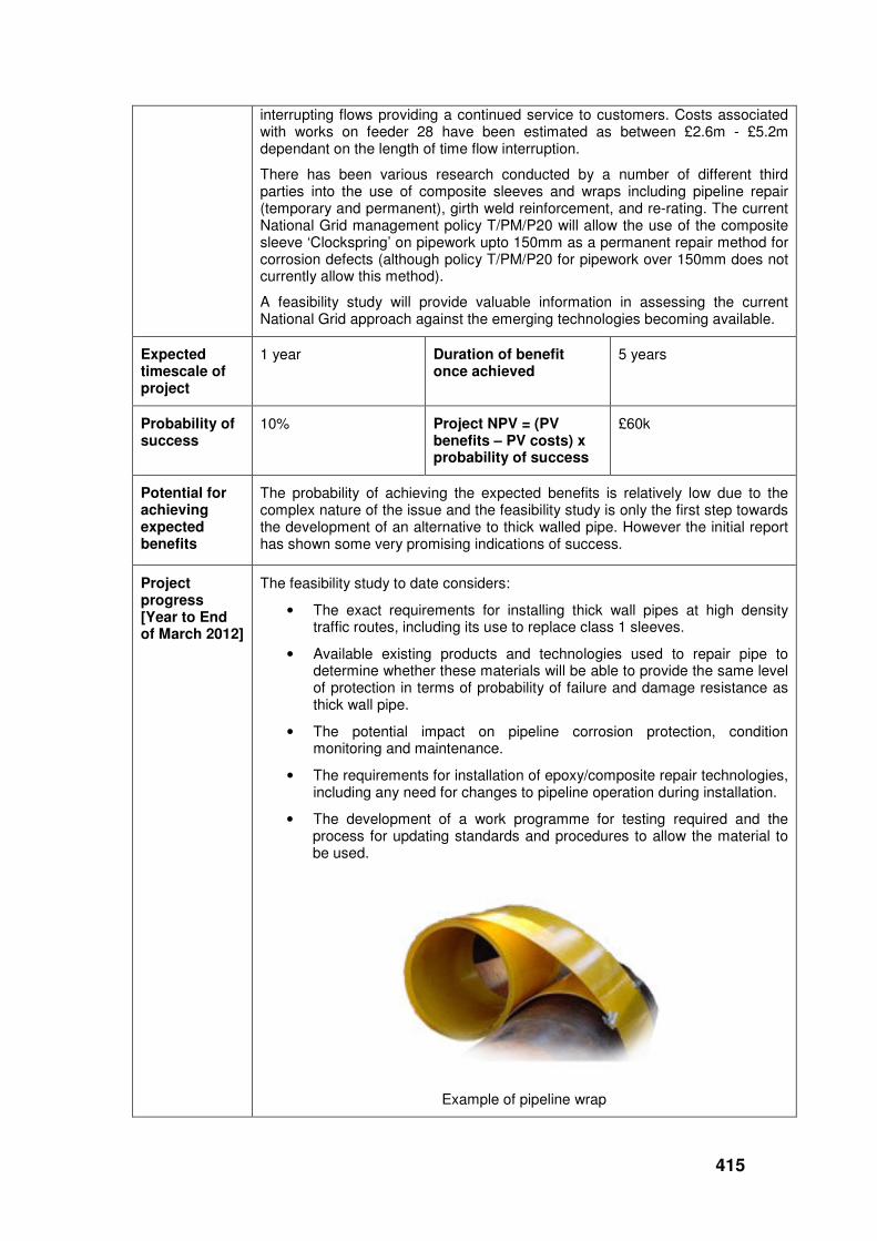
415
interrupting flows providing a continued service to customers. Costs associated with works on feeder 28 have been estimated as between £2.6m - £5.2m dependant on the length of time flow interruption.
There has been various research conducted by a number of different third parties into the use of composite sleeves and wraps including pipeline repair (temporary and permanent), girth weld reinforcement, and re-rating. The current National Grid management policy T/PM/P20 will allow the use of the composite sleeve ‘Clockspring’ on pipework upto 150mm as a permanent repair method for corrosion defects (although policy T/PM/P20 for pipework over 150mm does not currently allow this method).
A feasibility study will provide valuable information in assessing the current National Grid approach against the emerging technologies becoming available.
Expected timescale of project
1 year Duration of benefit once achieved
5 years
Probability of success
10%
Project NPV = (PV benefits – PV costs) x probability of success
£60k
Potential for achieving expected benefits
The probability of achieving the expected benefits is relatively low due to the complex nature of the issue and the feasibility study is only the first step towards the development of an alternative to thick walled pipe. However the initial report has shown some very promising indications of success.
Project progress [Year to End of March 2012]
The feasibility study to date considers:
• The exact requirements for installing thick wall pipes at high density traffic routes, including its use to replace class 1 sleeves.
• Available existing products and technologies used to repair pipe to determine whether these materials will be able to provide the same level of protection in terms of probability of failure and damage resistance as thick wall pipe.
• The potential impact on pipeline corrosion protection, condition monitoring and maintenance.
• The requirements for installation of epoxy/composite repair technologies, including any need for changes to pipeline operation during installation.
• The development of a work programme for testing required and the process for updating standards and procedures to allow the material to be used.
Example of pipeline wrap

416
Dependant upon the outcome of phase 1, a programme for the testing and analysis that are necessary to meet policy requirements will be developed.
Collaborative partners
None
R&D provider GL Noble Denton
417
Long Term Research
Project title Leveraged International Research Programmes for Gas Pipelines and Above Ground Facilities
Project Engineer
Tony Stonehewer
Description of project
Pipeline Research Council International (PRCI)
The PRCI facilitates a collaborative R&D programme, funded by contributions, based on the total length of pipelines operated by each member company. This is a global organisation managed out of the USA with a combination of membership and associate membership from America, Europe, Asia and Australia. Each member company contributes to the projects that most closely address their needs, but all member companies have access to the output of the complete programme.
European Pipeline Research Group (EPRG)
EPRG is a cooperation of European pipe manufacturers and gas transmission companies. EPRG undertakes a wide range of research directed to increase integrity and safety of gas transmission pipelines.
European Turbine Network (ETN)
The European Turbine Network (ETN) is a non-profit European association which brings together the gas turbine technology community for power generation and mechanical drive applications in Europe, representing 79 members from 17 European countries.
Expenditure for financial year
Internal £23k
External £88k
Total £110k
Expenditure in previous (IFI) financial years
Internal £37k
External £160k
Total £197k
Total project costs (collaborative + external + NG)
£307k Projected 2012/13 costs for NG
£0
Technological area and/or issue addressed by project
PRCI - The PRCI aims to conduct a collaboratively-funded research & development programme that enables energy pipeline companies around the world to provide safe, reliable, environmentally compatible, cost-efficient service to meet customer energy requirements.
The areas covered by the PRCI programme in 2011 that were supported by National Grid included the following:
• Design, Materials & Construction: 36% of National Grid subscription
• Operations & Integrity: 30%
• Compressor and pump station 21%
• Measurement: 7%
• Corrosion 7%
ETN
Cycle Efficiency: Improved performance of gas turbine components and intelligent system integration will enhance fuel efficiency and environmental performance.
Fuel Flexibility & Emissions: Gas turbines capable of operating in an efficient,
418
safe and reliable manner utilising a wide range of fuels whilst minimising polluting emissions such as NOx and aiming at zero CO2 emissions.
Materials Degradation & Repair Technologies: Extend the ultimate life and repair interval for hot section components.
Condition Monitoring, Instrumentation & Control: Aiming for 25,000 hours of gas turbine operation without intervention.
Project Benefits Rating
Project Residual Risk
Overall Project Score
Type(s) of innovation involved
Incremental
21 0 21
Expected benefits of project
PRCI - PRCI’s value proposition: “Formal cost / benefit studies of member participation show a consistently positive ratio of 4:1 to 7:1 from reduced costs of operations and maintenance, inspection, materials, design, construction and testing”
National Grid Transmission and National Grid Gas Distribution this year used their combined annual contribution of $153k to help launch 14 PRCI projects with a total cost of $2.8m. This represents more than 20:1 average leverage on National Grid supported projects.
EPRG - Improved system integrity knowledge, Improved corrosion protection, reduced 3rd party incidents leading to less supply disruptions. Networking opportunity with other pipeline operators, sharing information and best practice. It is very difficult to articulate the proposed benefits of these high level benefits until the output of each individual project is known.
Significant research leverage benefits of about 15:1, based on an NG contribution of €20k.
ETN - ETN promotes environmentally sound GT technology with reliable and low cost operation. Besides facilitating and coordinating research effort of different parties, bringing together key stakeholders in the gas turbine community, ETN also presents extensive networking opportunities and acts as solid platform for exchange of knowledge and experiences. ETN identifies research gaps and influences EU research agenda and policy-making at early stage.
Expected timescale of project
Ongoing -
Reviewed annually
Duration of benefit once achieved
Ongoing
Probability of success
70% Project NPV = (PV benefits – PV costs) x probability of success
>£1m
Potential for achieving expected benefits
The PRCI collaborative programme gives National Grid the opportunity to benefit from a significant number of highly leveraged projects which compliment much of the work on the overall IFI programme. It also provides a link with PRCI global membership and benefits of identifying emerging threats and opportunities.
The programme of work within EPRG has potential for achieving the expected benefits for National Grid due the collaborative nature of the projects. The R&D leverage ratio of 15:1 and the shared knowledge on best practice and incidents are the main benefits and a consistency between the Distribution and Transmission businesses.
National Grid predominantly uses ETN as a forum to help identify emerging issues and opportunities with gas turbine mechanical drives.
Project PRCI - The following PRCI projects were supported by National Grid this year:

419
progress [Year to End of March 2012]
Design, Materials & Construction
• Program to Evaluate the Long-term Performance of Composite Repair Systems
• Leak Prevention in CO2 Pipeline Valves • Development of CO2DECOM for determination of decompression waves • Sleeve End Fillet Weld Stress Intensity Factor Solutions - Year 2 • NASA TecFusion
Operations and Integrity
• Right of Way Automated Monitoring • Demonstration of Second Generation Satellite-based Pipeline Integrity
Management Pipeline Integrity using EMAT • Mechanical Damage Inspection and Characterization
Corrosion
• Seal healing coating
Compressor and Pump Station
• Collecting Cold Ambient Emissions Field Data on Solar's Titan 130 SoLoNOx Gas Turbine
• Compressor station NO2 modelling • Technology challenges for liquid CO2 pump stations
Measurement
• Effect of Upstream Piping Configurations on Ultrasonic Meter Bias
EPRG - Meetings of the EPRG Corrosion, Materials and Design Committee were attended. A large number of projects are currently ongoing :
Materials
• (EPRG 137) Assessment of delayed failure under constant pressure
• (EPRG 146) Development of a reliable model for evaluating the ductile fracture propagation resistance for high grade steel pipelines
• (EPRG 155) Assessment of delayed failure under constant pressure
• (EPRG 156) Guidelines for mechanised GMAW welding
• (EPRG 157) DWTT for small-diameter thick-walled pipe - seamless
• (EPRG 158) DWTT for small-diameter thick-walled pipe - inverse fracture
• (EPRG 160& 161) CO2 pipelines – fracture control & shock tube testing
Design
• (EPRG 141) Discrimination for mill features using MLF pigs for baseline inspections- Phase 1
• (EPRG 143) Extension of FFP and puncture resistance criteria to X80
• (EPRG 147) Development of an improved model for the burst strength of dent-gouge damage under sustained internal pressure loading - modelling & experimental

420
• (EPRG 162) Revision of EPRG weld defect guidelines
• (EPRG 164) Assessment of bending wrinkles
Corrosion
• (EPRG 149 & 150) HIC Assessment of low alloy steel line pipe for sour service application
• (EPRG 151) Assessment of sensitivity to hostile environments of damaged pipe, under cathodic protection and internal pressure
• (EPRG 154) Survey of sulphide stress cracking testing methodologies
• (EPRG 163) Long term resistance to adhesion loss of 3 layer polyolefin coatings
Two review meetings were held to discuss progress and implications of EPRG projects to National Grid pipelines. As part of these discussions, the documented procedures that are currently applied to gas transmission and distribution operations in the UK were reviewed to establish how to incorporate any knowledge gained from recent/ongoing EPRG projects.
ETN - Ongoing European Turbine Network projects include:
Cycle Efficiency, Fuel Flexibility and Emissions
• CFD Validation Study
• Dynamics of Combustion Instabilities
• EC Work on Interoperability - Harmonisation of Gas Quality
• Shale Gas Study
• Virtual testing
Materials Degradation & Repair Technologies and Condition Monitoring, Instrumentation & Control
• Advanced sensor technology for gas turbines
• Benefits of emission reduction retrofits
• Creep – fatigue database
• Hot boroscoping project
• Life limiting mechanisms database
• Filtration technology project
Asset Management
• Condition Monitoring
• Esreda collaboration
• Risk based decision making project
Collaborative partners
PRCI is a collaboration with National Grid Gas Distribution (UK) and 36 other companies with energy pipeline interests (23 based in the USA; 6 European; 4 Canadian; 1 South American; 1 Middle-Eastern, 1 Far-Eastern)
EPRG is a collaboration with National Grid Gas Distribution and 17 other European pipe manufacturers and gas transmission companies
ETN has 78 other members from 17 European countries
R&D provider PRCI (which uses a selection of Research Contractors, including large, multi-discipline corporations, non-profit institutions, small, pipeline niche firms, major colleges and universities)
EPRG (which uses a range of European Research Contractors)
GL Noble Denton ETN

421
National Grid plc 1-3 Strand, London WC2N 5EH, United Kingdom Registered in England and Wales 4031152