GAS MANIFOLD SYSTEMS & ACCESSORIES MANIFOLD SYSTEMS & ACCESSORIES ... Fittings and Piping ... for...
20
GAS MANIFOLD SYSTEMS & ACCESSORIES anniversary 2016 1946 th Manifold Catalog: GMF-2016
Transcript of GAS MANIFOLD SYSTEMS & ACCESSORIES MANIFOLD SYSTEMS & ACCESSORIES ... Fittings and Piping ... for...

GAS MANIFOLD SYSTEMS & ACCESSORIES
anniversary2016
1946
th
Manifold Catalog: GMF-2016

HOW TO ORDER
2 www.superiorprod.com
MANIFOLD SELECTION AND SIZING ..........................2
ABOUT SUPERIOR PRODUCTS ...................................3
MANIFOLD ASSEMBLIES:
Simplex Manifolds ...............................................4-5 Manifold Header Extensions ................................4-5 Modular Manifolds ..................................................6 Duplex Manifolds ...................................................7 Simple Duplex Manifolds ........................................8 SCMB / CPR Cradle Pack Manifolds........................8 Regulator, Manifold .................................................9 Commonly Used Pigtails .........................................9
SEMI-AUTOMATIC MANIFOLDS:
SAM Series .....................................................10-11 GMC Series .........................................................12 GML Series........................................... ................13
MANIFOLD ACCESSORIES:
Fittings and Piping ..........................................14-16 Line Station Drops ................................................17 Line Station Valves ................................................17 Line Station Regulators .........................................17 Valves, Manifold ...................................................18
WARRANTY INFORMATION ......................................19
Table Of Contents
1. Calculate maximum possible usageTotal # of welding/gas use stations X SCFH used per station = max possible usage
2. Determine duty cycle (Hours per day of gas use)8 hours/day, 16 hours/day, 24 hours/day
3. Determine total gas usage per day1. Max possible usage X 2. Duty cycle = 3. Total gas usage per day
4. Determine gas volume of cylinders to be used(Typical high pressure cylinder = 250 cubic feet, typical liquid = 4500 cubic feet)
5. Determine # of cylinders needed per day3. Total gas usage/day ÷ 4. Volume of cylinders = # of cylinders/day
6. Determine frequency of cylinder change outs desiredOnce a day, every third day, once a week etc. Gas supplier delivery schedule will help determine.
7. Determine size of each manifold service bank5. # of cylinders per day X 6. Frequency of changeouts = size of service bank
1. What gas/gas mix, CGA
2. Liquid or high pressure cylinders
3. What is the end use application
4. Required line pressure to application (PSIG)
5. Required maximum flow rate to application (SCFH)
6. Is interruption of gas service acceptable
7. Is notification of changeover or gas outage required
8. Total # of cylinders (use How To Properly Size A Manifold below)
Manifold Selection Criteria
How To Properly Size A Manifold

ABOUT SUPERIOR PRODUCTS
Call for more information or to place an order 800.651.9490 • www.superiorprod.com 3
Established in 1948 and celebrating 70 years of providing superior products coupled with excellent customer service, Superior Products continues to thrive and respond to changing markets.
With this new product update and extension of our Gas Manifold Systems and Accessories, Superior Products offers an expanded line of compressed gas manifolds, regulators, pigtails and fittings.
Superior Products’ gas manifold systems provide a reliable and safe way for large volumes of gas to be distributed. Manifold selection begins with choosing the type of manifold or control section. Superior Products offers header manifolds in a variety of custom configurations and options. Header manifolds include simplex, duplex, modular and simple duplex models. Partner with a manifold regulator and flexible pigtails for a complete system.
Superior Products’ semi-automatic manifolds give three options for uninterrupted gas service. All semi-automatic manifolds switch from depleted bank to full bank automatically and can be used for compressed gas or gas withdrawal from liquid dewars.
All products in this catalog as designed for standard industrial gases and meet or exceed the specifications on the Compressed Gas Association (CGA) and the National Fire Protection Association (NFPA). All assemblies are tested to at least 1.5 times working pressure.
For assistance please contact Superior Products customer service department at 800-651-9490.

4 www.superiorprod.com
The Superior Simplex Manifold system is designed to provide a single source of supply from one cylinder bank. This manifold is typically used as a high pressure back-up system for liquid or bulk tank systems in both industrial and medical applications.
The simplex manifold has a master shut-off valve with a single row of cylinders. Each header consists of 1/2” pipe, 1/2” tees or
crosses, header valves or inlet adaptors with check valves, master shut-off valve, end plug and mounting brackets. The end has a plug that allows for future expansion. The outlet regulator is ordered separately based on the required delivery pressure.
SPECIFICATIONS:• Maximum inlet pressure: 3000 PSIG• Manifold outlet: 1-11.5 NPS-RH or 1-11.5 NPS-LH• 1/2” brazed pipe & tees for maximum leak protection• Manifold regulator sold separately (see page 9)• Pigtails must be ordered separately (see page 9)
GMSM-HVR-580-02
All Superior manifolds are expandable to meet changing application requirements. Header extensions are shipped ready for addition to existing manifolds. Unit includes 1/2” piping, 1/2” tees, header valves or inlet adaptors with check valves and a mounting bracket. The end has an NPT plug that allows for future expansion.
All pigtails for Superior manifolds must be ordered separately.
• Specify right side extension (HVR) or left side extension (HVL)
• Model shown in photo is right hand header extension
GMHE-HVR-580-02
GAS MANIFOLD ASSEMBLIES: Simplex, Header Extensions
Simplex Manifolds (Left or Right Design) - GMSM Series
Manifold Header Extensions - GMHE Series
(regulator sold separately)
Ordering Guide
1. Choose your header type
2. Add a regulator
3. Add pigtails
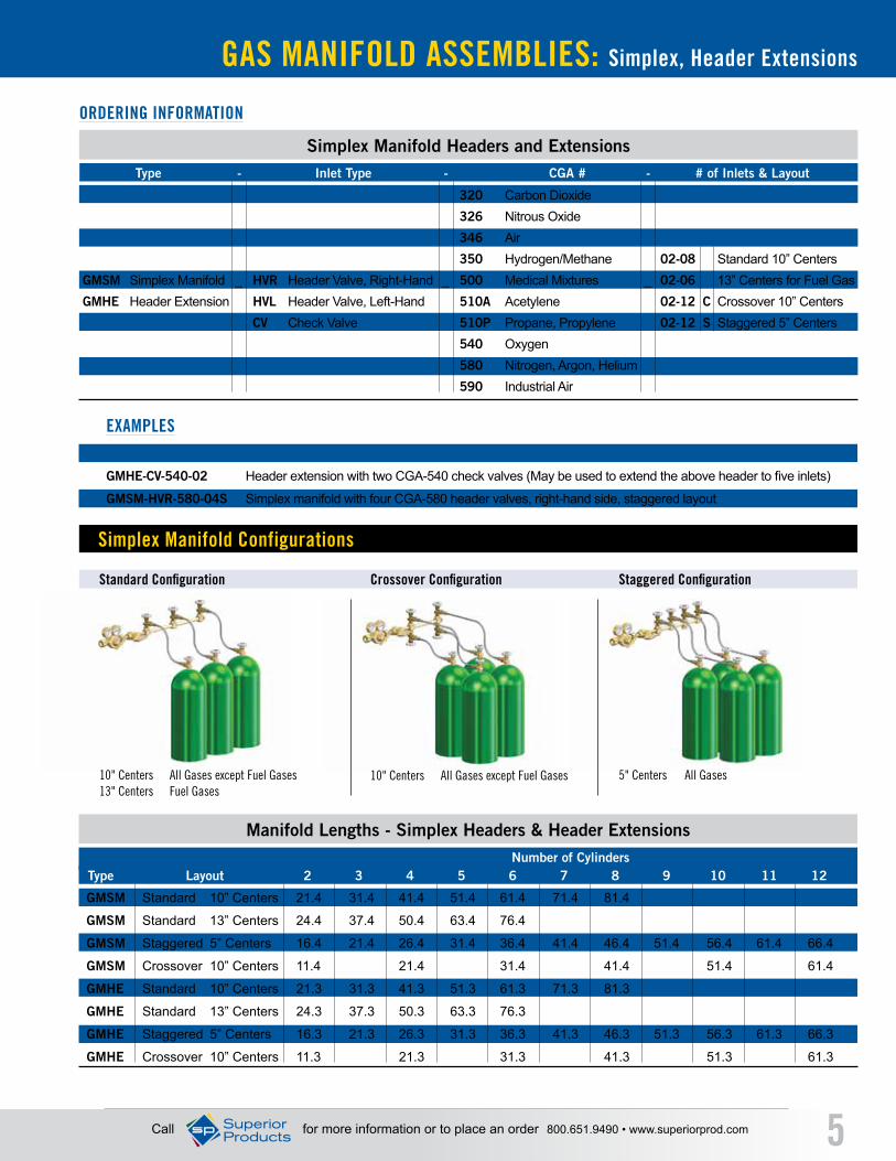
Staggered ConfigurationCrossover ConfigurationStandard Configuration
Simplex Manifold Configurations
Call for more information or to place an order 800.651.9490 • www.superiorprod.com 5
GAS MANIFOLD ASSEMBLIES: Simplex, Header Extensions
ORDERING INFORMATION
EXAMPLES
GMSM Standard 10” Centers 21.4 31.4 41.4 51.4 61.4 71.4 81.4
GMSM Standard 13” Centers 24.4 37.4 50.4 63.4 76.4
GMSM Staggered 5” Centers 16.4 21.4 26.4 31.4 36.4 41.4 46.4 51.4 56.4 61.4 66.4
GMSM Crossover 10” Centers 11.4 21.4 31.4 41.4 51.4 61.4
GMHE Standard 10” Centers 21.3 31.3 41.3 51.3 61.3 71.3 81.3
GMHE Standard 13” Centers 24.3 37.3 50.3 63.3 76.3
GMHE Staggered 5” Centers 16.3 21.3 26.3 31.3 36.3 41.3 46.3 51.3 56.3 61.3 66.3
GMHE Crossover 10” Centers 11.3 21.3 31.3 41.3 51.3 61.3
Manifold Lengths - Simplex Headers & Header Extensions
Type Layout 2 3 4 5 6 7 8 9 10 11 12
320 Carbon Dioxide 326 Nitrous Oxide 346 Air 350 Hydrogen/Methane 02-08 Standard 10” Centers
GMSM Simplex Manifold _ HVR Header Valve, Right-Hand _ 500 Medical Mixtures _ 02-06 13” Centers for Fuel GasGMHE Header Extension HVL Header Valve, Left-Hand 510A Acetylene 02-12 C Crossover 10” Centers
CV Check Valve 510P Propane, Propylene 02-12 S Staggered 5” Centers 540 Oxygen 580 Nitrogen, Argon, Helium 590 Industrial Air
Simplex Manifold Headers and Extensions Type - Inlet Type - CGA # - # of Inlets & Layout
GMSM-CV-540-03 Simplex manifold with three CGA-540 check valve inlets
GMHE-CV-540-02 Header extension with two CGA-540 check valves (May be used to extend the above header to five inlets)
GMSM-HVR-580-04S Simplex manifold with four CGA-580 header valves, right-hand side, staggered layout
Number of Cylinders
5" Centers All Gases10" Centers All Gases except Fuel Gases 13" Centers Fuel Gases
10" Centers All Gases except Fuel Gases
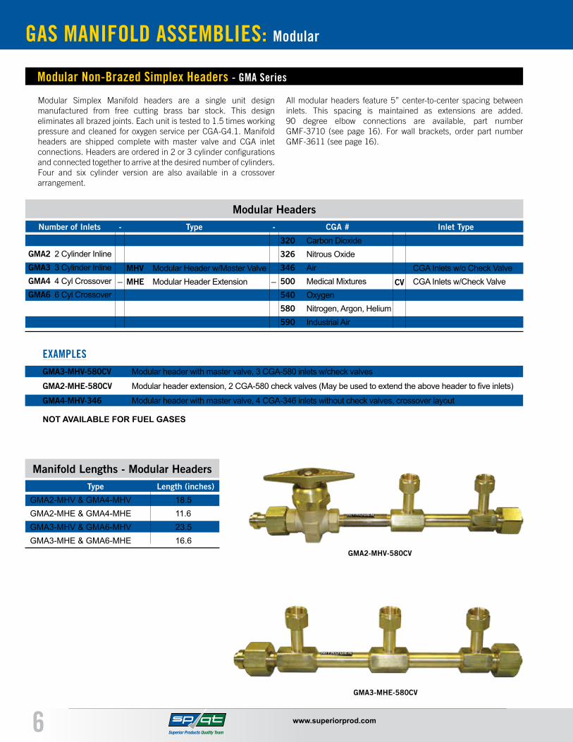
GAS MANIFOLD ASSEMBLIES: Modular
6 www.superiorprod.com
Modular Simplex Manifold headers are a single unit design manufactured from free cutting brass bar stock. This design eliminates all brazed joints. Each unit is tested to 1.5 times working pressure and cleaned for oxygen service per CGA-G4.1. Manifold headers are shipped complete with master valve and CGA inlet connections. Headers are ordered in 2 or 3 cylinder configurations and connected together to arrive at the desired number of cylinders. Four and six cylinder version are also available in a crossover arrangement.
All modular headers feature 5” center-to-center spacing between inlets. This spacing is maintained as extensions are added. 90 degree elbow connections are available, part number GMF-3710 (see page 16). For wall brackets, order part number GMF-3611 (see page 16).
Modular Non-Brazed Simplex Headers - GMA Series
Modular Headers Number of Inlets - Type - CGA # Inlet Type
EXAMPLES
GMA2-MHV & GMA4-MHV 18.5GMA2-MHE & GMA4-MHE 11.6GMA3-MHV & GMA6-MHV 23.5GMA3-MHE & GMA6-MHE 16.6
Manifold Lengths - Modular HeadersType Length (inches)
GMA2-MHV-580CV
GMA3-MHE-580CV
GMA2 2 Cylinder InlineGMA3 3 Cylinder InlineGMA4 4 Cyl CrossoverGMA6 6 Cyl Crossover
MHV Modular Header w/Master ValveMHE Modular Header Extension CV
CGA Inlets w/o Check ValveCGA Inlets w/Check Valve_ _
320 Carbon Dioxide326 Nitrous Oxide346 Air500 Medical Mixtures540 Oxygen580 Nitrogen, Argon, Helium590 Industrial Air
GMA3-MHV-580CV Modular header with master valve, 3 CGA-580 inlets w/check valves
GMA2-MHE-580CV Modular header extension, 2 CGA-580 check valves (May be used to extend the above header to five inlets)
GMA4-MHV-346 Modular header with master valve, 4 CGA-346 inlets without check valves, crossover layout
NOT AVAILABLE FOR FUEL GASES

GAS MANIFOLD ASSEMBLIES: Duplex
Call for more information or to place an order 800.651.9490 • www.superiorprod.com 7
Duplex Manifolds - GMDM Series
The Superior Duplex Manifold is designed to provide a dual source of supply via a primary and reserve bank of cylinders. Once the primary side has been depleted the reserve bank must be manually activated to return the system to working status.
The duplex manifold has two master shut-off valves allowing replacement of the exhausted bank of cylinders while the full bank of cylinders is in operation. The center section accommodates a
single regulator (sold separately). The manifold is shipped with master shut off valves, brazed 1/2” pipe & tees, header valves or inlet adaptors with check valves, end plugs and mounting brackets. The last module has an NPT plug that allows for future expansion. The outlet regulator is ordered separately based on the required delivery pressure.
GMDM-HV-580-04
SPECIFICATIONS:• Maximum inlet pressure: 3000 PSIG• Manifold outlet: 1/2” NPT• 1/2” brazed pipe & tees• Manifold regulator sold separately (see page 9)• Pigtails must be ordered separately (see page 9)
ORDERING INFORMATION
EXAMPLES
320 Carbon Dioxide
326 Nitrous Oxide
346 Air
350 Hydrogen/Methane
GMDM Duplex Manifold _ HV Header Valve _ 500 Medical Mixtures _ 04-16 Standard 10” Centers
CV Check Valve 510A Acetylene 04-12 13” Centers for Fuel Gas
510P Propane, Propylene
540 Oxygen
580 Nitrogen, Argon, Helium
590 Industrial Air
Duplex Manifolds
Type - Inlet Type - CGA # - # of Inlets & Layout
GMDM-HV-580-04 Duplex manifold with four CGA-580 header valves (two per side)
GMDM-CV-540-06 Duplex manifold with six CGA-540 check valve inlets (three per side)
(regulator sold separately)
GMDM Standard 10” Centers 52.8 72.8 92.8 112.8 132.8 152.8 172.8
GMDM Standard 13” Centers 64.8 90.8 116.8 142.8 168.8
Manifold Lengths - Duplex Headers (inches)
Type Layout 4 6 8 10 12 14 16Number of Cylinders
GAS MANIFOLD ASSEMBLIES: Simple Duplex, SCMB / CPR Series
8 www.superiorprod.com
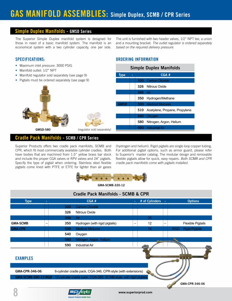
The Superior Simple Duplex manifold system is designed for those in need of a basic manifold system. The manifold is an economical system with a two cylinder capacity, one per side.
The unit is furnished with two header valves, 1/2” NPT tee, a union and a mounting bracket. The outlet regulator is ordered separately based on the required delivery pressure.
Simple Duplex Manifolds - GMSD Series
SPECIFICATIONS:• Maximum inlet pressure: 3000 PSIG• Manifold outlet: 1/2” NPT• Manifold regulator sold separately (see page 9)• Pigtails must be ordered separately (see page 9)
ORDERING INFORMATION
320 Carbon Dioxide
326 Nitrous Oxide
346 Air
350 Hydrogen/Methane
GMSD - 500 Medical Mixtures
510 Acetylene, Propane, Propylene
540 Oxygen
580 Nitrogen, Argon, Helium
590 Industrial Air
Simple Duplex ManifoldsType - CGA #
GMSD-580 (regulator sold separately)
Cradle Pack Manifolds - SCMB / CPR Series
Superior Products offers two cradle pack manifolds, SCMB and CPR, which fit most commercially available cylinder cradles. Both have bodies that are machined from 1.5” yellow brass bar stock and include the proper CGA valves or RPV valves and 24” pigtails. Specify the type of pigtail when ordering. Stainless steel flexible pigtails come lined with PTFE or ETFE for lighter than air gases
(hydrogen and helium). Rigid pigtails are single loop copper tubing. For additional pigtail options, such as armor guard, please refer to Superior’s master catalog. The modular design and removable flexible pigtails allow for quick, easy repairs. Both SCMB and CPR cradle pack manifolds come with pigtails installed.
320 Carbon Dioxide 326 Nitrous Oxide 346 Air 06
GMA-SCMB _ 350 Hydrogen (with rigid pigtails) _ 12 _ Flexible PigtailsGMA-CPR 500 Medical Mixtures 18 RGD Rigid Pigtails
540 Oxygen580 Nitrogen, Argon, Helium 590 Industrial Air
Cradle Pack Manifolds - SCMB & CPR Type - CGA # - # of Cylinders - Options
EXAMPLESGMA-SCMB-320-12 12-cylinder cradle pack, CGA-320, SCMB-style
GMA-CPR-346-06 6-cylinder cradle pack, CGA-346, CPR-style (with extensions)
GMA-SCMB-580-12-RGD 12-cylinder cradle pack, CGA-580, SCMB-style, with rigid pigtails
GMA-SCMB-320-12
GMA-CPR-346-06

MANIFOLD REGULATORS & PIGTAILS
Call for more information or to place an order 800.651.9490 • www.superiorprod.com 9
320 Carbon Dioxide PTF-320CV-320-24 PTF-320-320-24 PTFP-320-24 PT-4320326 Nitrous Oxide PTF-326CV-326-24 PTF-326-326-24 PTFP-326-24 PT-4326346 Air PTF-346CV-346-24 PTF-346-346-24 PTFP-346-24 PT-4346350 Hydrogen/Methane PTFT-350CV-350-24 PTFT-350-350-24 n/a PT-4350500 Medical Mixtures PTF-500CV-500-24 PTF-500-500-24 PTFP-500-24 PT-4500510 Acetylene* PTF-510FACV-510-24 n/a n/a n/a510 Propane, Propylene PTF-510CV-510-24 PTF-510-510-24 n/a PT-4510540 Oxygen PTF-540CV-540-24 PTF-540-540-24 PTFP-540-24 PT-4540580 Nitrogen, Argon PTF-580CV-580-24 PTF-580-580-24 PTFP-580-24 PT-4580580 Helium PTFT-580CV-580-24 PTFT-580-580-24 n/a PT-4580590 Industrial Air PTF-590CV-590-24 PTF-590-590-24 PTFP-590-24 PT-4590*Includes flash arrestor
Below are the common pigtails that are used on Superior manifolds. Superior gives you the option of ordering the specific pigtail you want when ordering your manifold. Pigtails may be ordered in different
lengths than stated below and also in a variety of other pressure ratings and materials (armor guard, spring guard, etc.) Refer to Superior’s master catalog for a complete selection of pigtails.
24” 24” 24” RIGID COPPER CGA # GAS SERVICE WITH CHECK VALVE WITHOUT CHECK VALVE WITH PERMANENT ENDS WITH LOOP
Commonly Used Pigtails - For Use On Manifolds
GMR-015LH 0-15 PSI 1-11.5 NPS-LH (CGA-1350) Fuel Gas
GMR-125LH 0-125 PSI 1-11.5 NPS-LH (CGA-1350) Fuel Gas
GMR-125RH 0-125 PSI 1-11.5 NPS-RH (CGA-1340) Other Than Fuel Gas
GMR-200RH 0-200 PSI 1-11.5 NPS-RH (CGA-1340) Other Than Fuel Gas
Model Pressure Range Connection Gas Service
SPECIFICATIONS:• All brass bonnet and body construction• High flow, 1/4” encapsulated seat• Neoprene diaphragm• Internal relief valve• Maximum inlet pressure: 3000 PSIG (except acetylene)• 1-11.5 NPS-RH or 1-11.5 NPS-LH inlet/outlet fittings• 3/8” NPT body ports
Manifold Regulator - GMR Series
GMR-125RH
GMA-CPR-346-06

10 www.superiorprod.com
SEMI-AUTOMATIC MANIFOLDS: SAM Series
Ordering Guide
Semi-Automatic Manifold - SAM Series
1. Choose your control section
2. Add pigtail kit or Add headers and pigtails
Use with high-pressure cylinders • • • •
Use with liquid cylinders (gas withdrawal) • • •
Maximum Inlet Pressure (PSIG) (oxygen/inert) 3000 3000 3000 n/a 230 350
(CO2 / N2O) 2000 2000 n/a 2000 230 350
(acetylene) 400 400 n/a n/a n/a n/a
(propane/LPG) 400 400 n/a n/a n/a n/a
Delivery Range (PSIG) (oxygen/inert) 0-125 30-125 50-200 n/a 40-85 40-180
(CO2 / N2O) 0-125 30-125 n/a 30-125 40-85 40-180
(acetylene) 0-15 0-15 n/a n/a n/a n/a
(propane/LPG) 0-125 0-30 n/a n/a n/a n/a
Max Flow Rate (SCFH) (oxygen/inert) 750 1200 2000 n/a 750 800
(CO2 / N2O) 25 35 n/a 500 750 800
(acetylene) 300 500 n/a n/a n/a n/a
(propane/LPG) 500 500 n/a n/a n/a n/a
Automatic Manifold Selection Matrix Description SAM GMC GMC-HP GMC-HL GML GML-HP
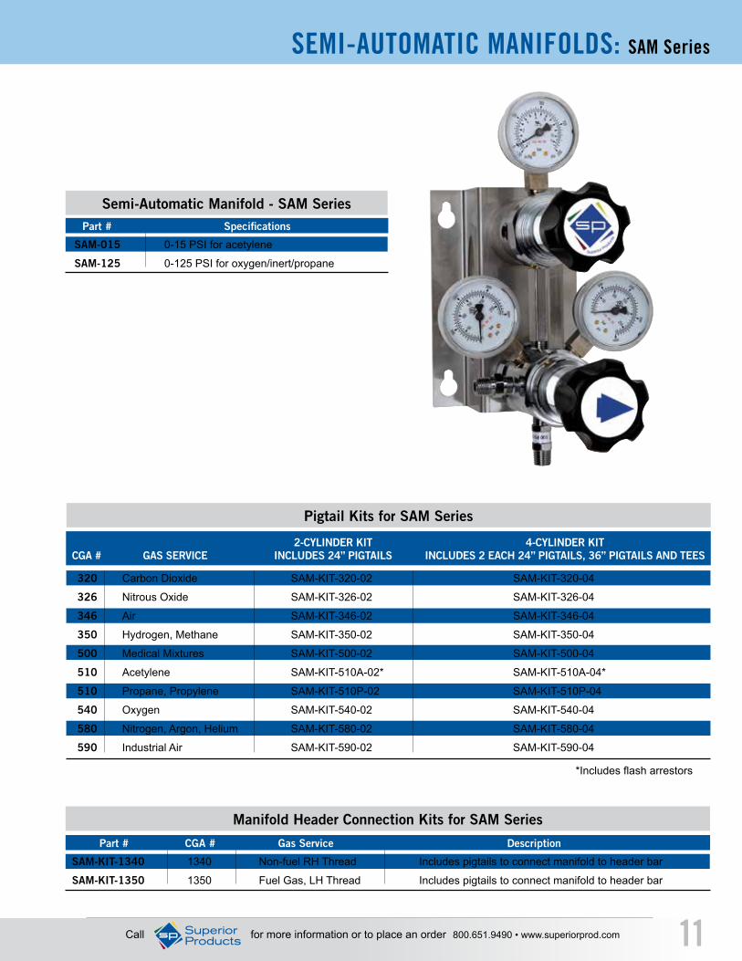
The SAM-125 and SAM-015 are semi-automatic switchover manifolds that prevent downtime by automatically switching gas supply from the primary cylinder bank to the reserve cylinder bank. The user resets the primary bank by simply turning the control knob to indicate the new primary supply. The unit is designed with a built-in outlet regulator to maintain a constant downstream delivery pressure. This unit is economically priced and ideal for most high pressure gases and gaseous withdrawal from liquid cylinders.
Pigtail kits are available to connect the manifold to two or four gas cylinders. To connect more than four cylinders, use a manifold header connection kit and any modular or brazed manifold headers (see pages 4-6).
SPECIFICATIONS:• Includes line control regulator • Inlet connections: 1/4” Male NPT • Outlet Connection: 1/4” Female NPT • 2” dual scale gauges • Chrome-plated brass with stainless steel regulator diaphragms • 9 pounds approximate weight• Pigtail kits ordered separately (see page 11)
Maximum Inlet Pressure (PSI) 400 400 3000 3000
Maximum Flow Rate (SCFH) 300 500 25 750
Delivery Range (PSI) 0-15 0-125 0-125 0-125
Switchover Pressure - Right Bank (PSI) 18 180 180 180
Switchover Pressure - Left Bank (PSI) 15 150 150 150
CARBON DIOXIDE, OXYGEN, INERTS, SPECIFICATIONS ACETYLENE PROPANE NITRIOUS OXIDE OTHER GASES
LINE STATION DROPS, LINE STATION VALVES & BALL VALVES
Call for more information or to place an order 800.651.9490 • www.superiorprod.com 11
SEMI-AUTOMATIC MANIFOLDS: SAM Series
SAM-015 0-15 PSI for acetylene
SAM-125 0-125 PSI for oxygen/inert/propane
Semi-Automatic Manifold - SAM Series Part # Specifications
320 Carbon Dioxide SAM-KIT-320-02 SAM-KIT-320-04
326 Nitrous Oxide SAM-KIT-326-02 SAM-KIT-326-04
346 Air SAM-KIT-346-02 SAM-KIT-346-04
350 Hydrogen, Methane SAM-KIT-350-02 SAM-KIT-350-04
500 Medical Mixtures SAM-KIT-500-02 SAM-KIT-500-04
510 Acetylene SAM-KIT-510A-02* SAM-KIT-510A-04*
510 Propane, Propylene SAM-KIT-510P-02 SAM-KIT-510P-04
540 Oxygen SAM-KIT-540-02 SAM-KIT-540-04
580 Nitrogen, Argon, Helium SAM-KIT-580-02 SAM-KIT-580-04
590 Industrial Air SAM-KIT-590-02 SAM-KIT-590-04
*Includes flash arrestors
2-CYLINDER KIT 4-CYLINDER KIT CGA # GAS SERVICE INCLUDES 24” PIGTAILS INCLUDES 2 EACH 24” PIGTAILS, 36” PIGTAILS AND TEES
Pigtail Kits for SAM Series
SAM-KIT-1340 1340 Non-fuel RH Thread Includes pigtails to connect manifold to header bar
SAM-KIT-1350 1350 Fuel Gas, LH Thread Includes pigtails to connect manifold to header bar
Part # CGA # Gas Service Description
Manifold Header Connection Kits for SAM Series
SEMI-AUTOMATIC MANIFOLDS: GMC Series
12 www.superiorprod.com
Pressure Differential Changeover for High-Pressure Cylinders
Pressure Differential Switchover from High Pressure Cylinders – GMC Series
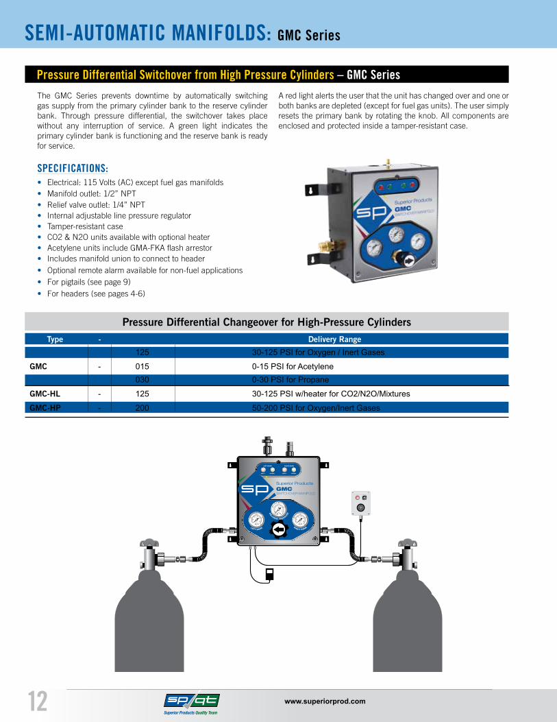
The GMC Series prevents downtime by automatically switching gas supply from the primary cylinder bank to the reserve cylinder bank. Through pressure differential, the switchover takes place without any interruption of service. A green light indicates the primary cylinder bank is functioning and the reserve bank is ready for service.
A red light alerts the user that the unit has changed over and one or both banks are depleted (except for fuel gas units). The user simply resets the primary bank by rotating the knob. All components are enclosed and protected inside a tamper-resistant case.
SPECIFICATIONS:• Electrical: 115 Volts (AC) except fuel gas manifolds• Manifold outlet: 1/2” NPT• Relief valve outlet: 1/4” NPT• Internal adjustable line pressure regulator• Tamper-resistant case• CO2 & N2O units available with optional heater• Acetylene units include GMA-FKA flash arrestor• Includes manifold union to connect to header• Optional remote alarm available for non-fuel applications• For pigtails (see page 9)• For headers (see pages 4-6)
125 30-125 PSI for Oxygen / Inert Gases
GMC - 015 0-15 PSI for Acetylene 030 0-30 PSI for Propane
GMC-HL - 125 30-125 PSI w/heater for CO2/N2O/Mixtures
GMC-HP - 200 50-200 PSI for Oxygen/Inert Gases
Type - Delivery Range

SEMI-AUTOMATIC MANIFOLDS: GML Series
Call for more information or to place an order 800.651.9490 • www.superiorprod.com 13
The GML Series is designed specifically to regulate and monitor vaporized gas from cryogenic cylinders. The GML series prevents downtime by automatically switching gas supply from the primary cylinder bank to the reserve cylinder bank. Through pressure differential, the switchover takes place without any interruption of service. A green light indicates the primary cylinder bank is
functioning and the reserve bank is ready for service. A red light alerts the user that the unit has changed over and one or both banks are depleted. The user simply resets the primary bank by rotating the knob. All components are enclosed and protected inside a tamper-resistant case.
Pressure Differential Switchover for Gas Withdrawal from Liquid Cylinders – GML Series
SPECIFICATIONS:• Available up to 3 cylinders per side• Electrical: 115 Volts (AC)• Maximum Inlet Pressure: 230 or 350 PSI• Manifold outlet: 1/2” NPT• Relief valve outlet: 1/4” NPT• GML-085 for use with 235 PSI relief valve liquid cylinders• GML-HP-180 for use with 350 PSI relief valve liquid cylinders• Economizer circuit helps prevent reserve cylinder from wasting gas due to venting to atmosphere • Optional remote alarm available• Pigtail kits must be ordered separately (see below)
GML - 085 (40-85 PSI for cylinders w/ 235 PSI relief valve)
GML-HP - 180 (40-180 PSI for cylinders w/ 350 PSI relief valve)
Type - Delivery Range
Pressure Differential Changeover for Liquid Cylinder Gas Withdrawal
320 Carbon Dioxide GML-KIT-320-02 GML-KIT-320-04 GML-KIT-320-06
326 Nitrous Oxide GML-KIT-326-02 GML-KIT-326-04 GML-KIT-326-06
540 Oxygen GML-KIT-540-02 GML-KIT-540-04 GML-KIT-540-06
580 Nitrogen, Argon, Helium GML-KIT-580-02 GML-KIT-580-04 GML-KIT-580-06
2-CYLINDER KIT 4-CYLINDER KIT 6-CYLINDER KIT CGA # GAS SERVICE 2 x 72” PIGTAILS 4 x 72” PIGTAILS & 2 x Tees 6 x 72” PIGTAILS & 2 x Crosses
Pigtail Kits for GML Series
• Black polyester blend perforated cover • 3/8” ID synthetic core • 2250 PSI working pressure

MANIFOLD ACCESSORIES
14 www.superiorprod.com
Superior’s flash arrestor kit provides flash back, reverse flow and pressure relief protection in the compact device. This unit is included with any Superior Products acetylene manifold for
more than 2 cylinders. It is also available as an option for use with hydrogen or propane manifolds.
Dry Type Flash Back Arrestors - GMA-FK Series
Brass Manifold Pipe and Pipe Fittings
FEATURES:• No water or fluid to check or replenish• Approved safety device under ANSI Z49• Help meet OSHA & NFPA safety standards• Built in relief valve meets NFPA 51 requirements
GMA-FKA Acetylene 300 1/2 NPT 15 PSIG
GMA-FKP-40 Propane 300 1/2 NPT 40 PSIG
GMA-FKP-60 Propane 300 1/2 NPT 60 PSIG
GMA-FKH Hydrogen 300 1/2 NPT 40 PSIG
Part # Type Capacity Inlet/Outlet Relief Valve
Fittings are machined from CDA-360 brass, stress relieved and cleaned for oxygen service. All measurements are in inches.
GMF-3011 1/2 - 14 NPT 1/2 - 14 NPT 1 - 5/16 3/4GMF-3012 1/2 - 14 NPT .843 - .847 1 - 5/16 3/4GMF-3013 1/2 - 14 NPT .843 - .847 1 - 5/16 3/4
GMF-3041 1/2 - 14 NPT 1/2 - 14 NPT 1/2 - 14 NPT 1 - 1/2GMF-3042 .843 - .847 1/2 - 14 NPT 1/2 - 14 NPT 1 - 1/2GMF-3043 .843 - .847 Slip Thru 1/2 - 14 NPT 1 - 1/2
Part # Ref. A Ref. B Ref. F Ref. G Part # Ref. A Ref. B Ref. C & D Ref. E
Pipe Elbows - 3,000 PSI Pipe Crosses - 3,000 PSI
GMF-3021 1/2 - 14 NPT 1/2 - 14 NPT 1/2 - 14 NPT 1 - 1/2
GMF-3022 1/2 - 14 NPT 1/2 - 14 NPT .843 - .847 1 - 1/2
GMF-3023 .843 - .847 1/2 - 14 NPT 1/2 - 14 NPT 1 - 1/2
GMF-3033 .843 - .847 Slip Thru 1/2 - 14 NPT 1 - 1/2GMF-3034 .843 - .847 Slip Thru .843 - .847 1 - 1/2
Part # Ref. A Ref. B Ref. C Ref. E Part # Ref. A Ref. B Ref. C Ref. E
Pipe Tees - 3,000 PSI

LINE STATION DROPS, LINE STATION VALVES & BALL VALVES MANIFOLD ACCESSORIES
Call for more information or to place an order 800.651.9490 • www.superiorprod.com 15
Pipe Nipples, Threaded Ends / Pipe Lengths, Plain Ends - 3,000 PSI
Bulk Pipe Lengths, Plain Ends
GMF-3214
GMF-3224
FEATURES:• Cleaned for oxygen service• Suitable for acetylene• Made from CDA-360 Brass• Special lengths available upon request
FEATURES:• NOT CLEANED for oxygen service• Suitable for acetylene• Made from CDA-360 brass
NOTE: GMF-3237 and GMF-6237 must ship via common carrier
1.5 n/a GMF-3211
2 GMF-3222 GMF-3212
4 GMF-3223 GMF-3213
6 GMF-3224 GMF-32149.75 GMF-3225 GMF-321512.75 GMF-3226 GMF-3216
6 GMF-3236 GMF-6236
12 GMF-3237 GMF-6237
Length Unthreaded Threaded (inches) 1/2” Nominal Pipe 1/2 - 14 NPT
Length Unthreaded Unthreaded (feet) 1/2” Nominal Pipe 3/4” Nominal Pipe

Union Bushings Wall Bracket
GMF-3332
GMF-3331 1 -11.5 NPS-RH 3/8 -18 NPT 3.125
GMF-3332 1 -11.5 NPS-RH 1/2 -14 NPT 2.187
GMF-3335 1 -11.5 NPS-LH 3/8 -18 NPT 3.125
GMF-3336 1 -11.5 NPS-LH 1/2 -14 NPT 2.187
Part # Thread Pipe Thread Length
MANIFOLD FITTINGS & PIPING
Union Bushings without Filter - 3,000 PSI
16 www.superiorprod.com
Union 90° Union Plug
Image not to scale
GMF-3710 GMA-RH-PLUG
Part No. Thread Part No. Thread
GMA-RH-PLUG 1 -11.5 NPS-RH-INT.
GMA-LH-PLUG 1 -11.5 NPS-LH-INT.
GMF-3710 1 -11.5 NPS-RH
GMF-3711 1 -11.5 NPS-LH
Union Nuts Union Nipples
GMF-3326GMF-3311
Part No. Thread Part No. Thread Length
GMF-3311 1 -11.5 NPS-RH-INT.
GMF-3312 1 -11.5 NPS-LH-INT.
GMF-3321 3/8 -18 NPT 2.40
GMF-3326 1/2 -14 NPT 2.94
Part No. Description
GMF-3611 for use with GMSM, GMHE, Modular, GMDM manifolds (or any 1/2” nominal pipe)

MANIFOLD FITTINGS & PIPING
Call for more information or to place an order 800.651.9490 • www.superiorprod.com 17
Line Station Drops, Valves & Regulators - 200 PSI
GMA-SSD-022V-01 Oxygen Single 9/16 -18 RH “B” size valve
GMA-SSD-022V-02 Oxygen Double 9/16 -18 RH “B” size valve
GMA-SSD-023V-01 Fuel Gas Single 9/16 -18 LH “B” size valve
GMA-SSD-023V-02 Fuel Gas Double 9/16 -18 LH “B” size valve
GMA-SSD-024V-01 Oxygen Single 7/8 -14 RH “C” size valve
GMA-SSD-024V-02 Oxygen Double 7/8 -14 RH “C” size valve
GMA-SSD-025V-01 Fuel Gas Single 7/8 -14 LH “C” size valve
GMA-SSD-025V-02 Fuel Gas Double 7/8 -14 LH “C” size valve
Part # Gas Service No. of Outlets Outlet Size
GMV-1025
GMV-1024 200 psi CGA-024 1/2 -14 NGT
GMV-1025 200 psi CGA-025 1/2 -14 NGT
Part No. Operating Pressure CGA Outlet Valve Inlet
Station Valves
Line Station Drops
Station Regulators
GSR-024-015 Oxygen 0-15 PSI 7/8-14 RH-INT (CGA-024) 9/16-18 LH-EXT (CGA-022)
GSR-024-050 Oxygen 0-50 PSI 7/8-14 RH-INT (CGA-024) 9/16-18 LH-EXT (CGA-022)
GSR-024-125 Oxygen 0-125 PSI 7/8-14 RH-INT (CGA-024) 9/16-18 LH-EXT (CGA-022)
GSR-024-200 Oxygen 0-200 PSI 7/8-14 RH-INT (CGA-024) 9/16-18 LH-EXT (CGA-022)
GSR-025-001 Fuel Gas 0-1 PSI 7/8-14 LH-INT (CGA-025) 9/16-18 LH-EXT (CGA-023)
GSR-025-015 Fuel Gas 0-15 PSI 7/8-14 LH-INT (CGA-025) 9/16-18 LH-EXT (CGA-023)
GSR-025-050 Fuel Gas 0-50 PSI 7/8-14 LH-INT (CGA-025) 9/16-18 LH-EXT (CGA-023)
GSR-034-050 Inert / Air 0-50 PSI 7/8-14 RH-EXT (CGA-034) 5/8-18 RH-INT (CGA-032)
GSR-034-125 Inert / Air 0-125 PSI 7/8-14 RH-EXT (CGA-034) 5/8-18 RH-INT (CGA-032)
GSR-034-200 Inert / Air 0-200 PSI 7/8-14 RH-EXT (CGA-034) 5/8-18 RH-INT (CGA-032)
Model Gas Service Delivery Pressure Inlet Connection (“C” Size) Outlet Connection (“B” Size)
GSR-024-125

MANIFOLD VALVES
18 www.superiorprod.com
Ball Valves
Manifold Valves
Master Shut-Off Valves - 3,000 PSI
GMV-1540
GMV-1580
GMV-1001 GMV-1001V
FEATURES:• Forged brass body• PTFE packing• Kel-F seat
Part # Inlet & Outlet Size
GMV-334 1/4 female NPT
GMV-338 1/2 female NPT
GMV-3312 3/4 female NPT
Brass body, hot forged brass ball valve, 600 PSI ratedSafe for use with acetylene
Part # Inlet Outlet
GMV-1001 1/2 -14 NPT 1/2 -14 NPT
GMV-1001V 1/2 -14 NPT 1/2 -14 NPT
GMV-1341 1-11.5 NPS-RH-EXT 1-11.5 NPS-RH-INT
GMV-11350 1-11.5 NPS-LH-EXT 1-11.5 NPS-LH-INT
GMV-1300 250 PSI CGA-300 1/2 -14 NGTGMV-1320 3,000 PSI CGA-320 1/2 -14 NGTGMV-1326 3,000 PSI CGA-326 1/2 -14 NGTGMV-1346 3,000 PSI CGA-346 1/2 -14 NGTGMV-1350 3,000 PSI CGA-350 1/2 -14 NGTGMV-1510 250/500 PSI CGA-510 1/2 -14 NGTGMV-1540 3,000 PSI CGA-540 1/2 -14 NGTGMV-1580 3,000 PSI CGA-580 1/2 -14 NGTGMV-1590 3,000 PSI CGA-590 1/2 -14 NGTGMV-3346 3,000 PSI CGA-346 3/4 -14 NGTGMV-3350 3,000 PSI CGA-350 3/4 -14 NGTGMV-3540 3,000 PSI CGA-540 3/4 -14 NGTGMV-3580 3,000 PSI CGA-580 3/4 -14 NGTGMV-3660SS 3,000 PSI CGA-660 3/4 -14 NGTGMV-3680 4,700 PSI CGA-680 3/4 -14 NGTGMV-3702 6,400 PSI CGA-702 3/4 -14 NGT
Part # Operating Pressure CGA Outlet Valve Inlet
GMV-338
WARRANTY
Call for more information or to place an order 800.651.9490 • www.superiorprod.com 19
WARRANTY:
The manufacturer warrants the products sold hereunder to be free from defects in material and workmanship at the date of shipment. Please note the distinction between “defects” and “damage” as used in this warranty: defects are covered because we, the manufacturer, are responsible: however, we have no control over damage caused by such things as misuse or improper installation. Therefore, damage for any reason is not covered under this warranty.
WHAT THE MANUFACTURER WILL DO:
If you, the Buyer, meet the eligibility requirements and obligations listed below, then we shall, within thirty (30) days of receipt of a timely claim and the parts claimed to be defective, inspect the parts and repair or replace, at our option, any parts which we determine were defective at the time of shipment from us. However, if we determine that the parts were defective and also that circumstances are such as to prevent us from remedying the warranted defects by repair or replacement, then we may at our option, refund you the purchase price of the parts.
ELIGIBILITY REqUIREMENTS & OBLIGATIONS OF BUYER:
You are eligible to obtain service under this warranty if you are the original consumer purchaser, either from us directly or from a seller who stocks our product for resale. However, in order for you to obtain service under this warranty, you must do the following:
1. Contact Superior Products to obtain a QCA number for the item(s) to be returned.
2. Send a claim in writing along with samples of the parts claimed to be defective to us freight prepaid.
3. Have your claim and sample parts delivered within ninety (90) days from the date of shipment of the parts from our factory.
However, if you bought the parts for resale, or if you bought the parts from someone who bought them for resale, then you must deliver the claim and the parts to us within ninety (90) days from the date of re sale–except under no circumstances shall we honor any claim which fails to be delivered to us with the parts within one hundred and eighty (180) day from the date of shipment of the parts from our factory.
Your claim should be in typed or printed form and include the following information:
1. Your name and address; 2. The name and address of the seller of the parts; 3. The date of purchase of the parts; 4. A short description of the alleged defect; 5. Proof of the purchase of the parts, for example, a receipt or canceled check.6. QCA number
WHAT IS NOT COVERED UNDER THIS WARRANTY (LIMITATION OF LIABILITY):As stated above, damage for any reason is not covered under this warranty. Furthermore NO OTHER WARRANTY, WHETHER EXPRESS OR IMPLIED, INCLUDING ANY WARRANTY OF MERCHANTABILITY OR FITNESS FOR A PARTICULAR PURPOSE, SHALL EXIST IN CONNECTION WITH THE SALE OR USE OF OUR PRODUCTS. However, some states do not allow limitations on how an implied warranty lasts, so this limitation may not apply to you. Also, since this is a limited warranty, WE SHALL NOT, UNDER ANY CIRCUMSTANCES, BE LIABLE FOR ANY OTHER CHARGES, LABOR COSTS, OR ANY OTHER INCIDENTAL OR CONSEQUENTIAL LOSSES OR DAMAGES OF ANY KIND OR DESCRIPTION WHATSOEVER ARISING OUT OF, OR IN ANYWAY RELATING TO, ANY BREACH OF THIS WARRANTY OR CLAIMED DEFECT IN, OR NON-PERFORMANCE OF, OUR PRODUCTS. However, some states do not allow the exclusion or limitation of incidental or consequential damages, so this limitation or exclusion may not apply to you. This warranty also excludes commercial and other non-consumer purchasers other than the original consumer purchaser.
WE HAVE NO AGENTS:We do not authorize any person to create for us any obligation of liability in connection with our products.
LEGAL RIGHTS:This warranty gives you specific legal rights, and you may also have other rights which vary from state to state (province to province in Canada).
Your claim, along with the part(s) and QCA number written on outside of box
should be sent to:
Superior Products3786 Ridge Road
Cleveland, Ohio 44144-1175ATTN: QCA DEPT.
Limited Warranty
anniversary2016
1946
th
Industrial Hospital Specialty
Manifold Catalog GMF-2016 (DSD - 1500)
VISIT WWW.SUPERIORPROD.COMTO LEARN MORE ABOUT OUR OTHER PRODUCT LINES
3786 Ridge Rd. | Cleveland, OH | 44144 | Ph. 800-651-9490 | Fx. 216-651-4071