Gas cylinders — Transportable refillable welded steel ... Standards are drafted in accordance with...
40
Reference number ISO 22991:2004(E) © ISO 2004 INTERNATIONAL STANDARD ISO 22991 First edition 2004-05-01 Gas cylinders — Transportable refillable welded steel cylinders for liquefied petroleum gas (LPG) — Design and construction Bouteilles à gaz — Bouteilles en acier soudé transportables et rechargeables pour gaz de pétrole liquéfié (GPL) — Conception et fabrication
Transcript of Gas cylinders — Transportable refillable welded steel ... Standards are drafted in accordance with...

Reference numberISO 22991:2004(E)
© ISO 2004
INTERNATIONAL STANDARD
ISO22991
First edition2004-05-01
Gas cylinders — Transportable refillable welded steel cylinders for liquefied petroleum gas (LPG) — Design and construction
Bouteilles à gaz — Bouteilles en acier soudé transportables et rechargeables pour gaz de pétrole liquéfié (GPL) — Conception et fabrication

ISO 22991:2004(E)
PDF disclaimer This PDF file may contain embedded typefaces. In accordance with Adobe's licensing policy, this file may be printed or viewed but shall not be edited unless the typefaces which are embedded are licensed to and installed on the computer performing the editing. In downloading this file, parties accept therein the responsibility of not infringing Adobe's licensing policy. The ISO Central Secretariat accepts no liability in this area.
Adobe is a trademark of Adobe Systems Incorporated.
Details of the software products used to create this PDF file can be found in the General Info relative to the file; the PDF-creation parameters were optimized for printing. Every care has been taken to ensure that the file is suitable for use by ISO member bodies. In the unlikely event that a problem relating to it is found, please inform the Central Secretariat at the address given below.
ISO 22991:2004(E)
© ISO 2004 – All rights reserved iii
Contents Page
Foreword............................................................................................................................................................ iv Introduction ........................................................................................................................................................ v 1 Scope...................................................................................................................................................... 1 2 Normative references ........................................................................................................................... 1 3 Terms and definitions........................................................................................................................... 2 4 Symbols ................................................................................................................................................. 3 5 Materials................................................................................................................................................. 3 6 Design .................................................................................................................................................... 4 6.1 General requirements ........................................................................................................................... 4 6.2 Calculation of cylindrical shell thickness........................................................................................... 5 6.3 Design of ends concave to pressure .................................................................................................. 5 6.4 Ends of other shapes............................................................................................................................ 9 6.5 Minimum wall thickness ....................................................................................................................... 9 6.6 Design of openings............................................................................................................................... 9 6.7 Valve protection .................................................................................................................................... 9 7 Construction and workmanship ........................................................................................................ 10 7.1 Welding qualification .......................................................................................................................... 10 7.2 Plates and pressed parts.................................................................................................................... 10 7.3 Welded joints....................................................................................................................................... 10 7.4 Tolerances ........................................................................................................................................... 10 7.5 Non-pressure-containing attachments ............................................................................................. 11 7.6 Valve protection .................................................................................................................................. 11 7.7 Closure of openings ........................................................................................................................... 11 7.8 Heat treatment ..................................................................................................................................... 11 8 Testing.................................................................................................................................................. 12 8.1 Mechanical testing .............................................................................................................................. 12 8.2 Burst test under hydraulic pressure ................................................................................................. 17 8.3 Pressure test ....................................................................................................................................... 18 8.4 Radiographic and macro examination.............................................................................................. 18 8.5 Visual examination of the surface of the weld................................................................................. 20 8.6 Pressure cycling (fatigue) test........................................................................................................... 20 9 Acceptance procedure ....................................................................................................................... 21 9.1 General ................................................................................................................................................. 21 9.2 Batch testing ....................................................................................................................................... 21 9.3 Failure to meet batch test requirements........................................................................................... 23 10 Technical requirements for type approval ....................................................................................... 23 11 Marking................................................................................................................................................. 24 12 Certification ......................................................................................................................................... 24 Annex A (normative) Manufacturer's marking .............................................................................................. 25 Annex B (informative) Examples of type approval and production test certificates................................. 26
BA178AF3EC677050DBAC9B8DA5349567ADC990EEFF93F3B562D565BBCCE551B04FB30348A9F905D2BEBE2EE710159EC8B560C0BF30F077189D3B68E26A9F3C8A6364EAF5157E4DFF4A2F011E10AD206AF0BD6437B2B1BD93F7746FD35D925920EF33
A&
I-N
orm
enab
on
nem
ent
- S
iem
ens
AG
- K
d.-
Nr.
9863
45 -
Ab
o-N
r.00
0027
03/0
05/0
01 -
200
4-06
-25
10:0
6:11
ISO 22991:2004(E)
iv © ISO 2004 – All rights reserved
Foreword
ISO (the International Organization for Standardization) is a worldwide federation of national standards bodies (ISO member bodies). The work of preparing International Standards is normally carried out through ISO technical committees. Each member body interested in a subject for which a technical committee has been established has the right to be represented on that committee. International organizations, governmental and non-governmental, in liaison with ISO, also take part in the work. ISO collaborates closely with the International Electrotechnical Commission (IEC) on all matters of electrotechnical standardization.
International Standards are drafted in accordance with the rules given in the ISO/IEC Directives, Part 2.
The main task of technical committees is to prepare International Standards. Draft International Standards adopted by the technical committees are circulated to the member bodies for voting. Publication as an International Standard requires approval by at least 75 % of the member bodies casting a vote.
Attention is drawn to the possibility that some of the elements of this document may be the subject of patent rights. ISO shall not be held responsible for identifying any or all such patent rights.
ISO 22991 was prepared by Technical Committee ISO/TC 58, Gas cylinders, Subcommittee SC 3, Cylinder design.
BA178AF3EC677050DBAC9B8DA5349567ADC990EEFF93F3B562D565BBCCE551B04FB30348A9F905D2BEBE2EE710159EC8B560C0BF30F077189D3B68E26A9F3C8A6364EAF5157E4DFF4A2F011E10AD206AF0BD6437B2B1BD93F7746FD35D925920EF33
A&
I-N
orm
enab
on
nem
ent
- S
iem
ens
AG
- K
d.-
Nr.
9863
45 -
Ab
o-N
r.00
0027
03/0
05/0
01 -
200
4-06
-25
10:0
6:11
Als Papierkopie - kein Änderungsdienst / Printed copy - no alert service

ISO 22991:2004(E)
© ISO 2004 – All rights reserved v
Introduction
This International Standard calls for the use of substances and procedures that may be injurious to health if adequate precautions are not taken. It refers only to technical suitability and does not absolve the user from legal obligations relating to health and safety at any stage. It has been assumed in the drafting of this International Standard, that the execution of its provisions is entrusted to appropriately qualified and experienced people.
BA178AF3EC677050DBAC9B8DA5349567ADC990EEFF93F3B562D565BBCCE551B04FB30348A9F905D2BEBE2EE710159EC8B560C0BF30F077189D3B68E26A9F3C8A6364EAF5157E4DFF4A2F011E10AD206AF0BD6437B2B1BD93F7746FD35D925920EF33
A&
I-N
orm
enab
on
nem
ent
- S
iem
ens
AG
- K
d.-
Nr.
9863
45 -
Ab
o-N
r.00
0027
03/0
05/0
01 -
200
4-06
-25
10:0
6:11
Als Papierkopie - kein Änderungsdienst / Printed copy - no alert service
INTERNATIONAL STANDARD ISO 22991:2004(E)
© ISO 2004 – All rights reserved 1
Gas cylinders — Transportable refillable welded steel cylinders for liquefied petroleum gas (LPG) — Design and construction
1 Scope
This International Standard specifies minimum requirements concerning material, design, construction and workmanship, procedure and test at manufacture of transportable refillable welded steel liquefied petroleum gas (LPG) cylinders of water capacity up to and including 150 l, exposed to ambient temperatures.
2 Normative references
The following referenced documents are indispensable for the application of this document. For dated references, only the edition cited applies. For undated references, the latest edition of the referenced document (including any amendments) applies.
ISO 643, Steels — Micrographic determination of the apparent grain size
ISO 1106-1:1984, Recommended practice for radiographic examination of fusion welded joints — Part 1: Fusion welded butt joints in steel plates up to 50 mm thick
ISO 1106-3:1984, Recommended practice for radiographic examination of fusion welded joints — Part 3: Fusion welded circumferential joints in steel pipes of up to 50 mm wall thickness
ISO 2504:1973, Radiography of welds and viewing conditions for films — Utilization of the recommended patterns of image quality indications (I.Q.I.)
ISO 4136, Destructive tests on welds in metallic materials — Transverse tensile test
ISO 4978, Flat rolled steel products for welded gas cylinders
ISO 5178, Destructive tests on welds in metallic materials — Longitudinal tensile test on weld metal in fusion welded joints
ISO 5817, Welding — Fusion-welded joints in steel, nickel, titanium and their alloys (beam welding excluded) — Quality levels for imperfections
ISO 6892, Metallic materials — Tensile testing at ambient temperature
ISO 7438, Metallic materials — Bend test
ISO 9606-1, Approval testing of welders — Fusion Welding — Part 1: Steels
ISO 9956-3, Specification and approval of welding procedures for metallic materials — Part 3: Welding procedure tests for arc welding of steels
ISO 10920, Gas cylinders — 25E taper thread for connection of valves to gas cylinders — Specification
ISO 11116-1, Gas cylinders — 17E taper thread for connection of valves to gas cylinders — Part 1: Specifications
BA178AF3EC677050DBAC9B8DA5349567ADC990EEFF93F3B562D565BBCCE551B04FB30348A9F905D2BEBE2EE710159EC8B560C0BF30F077189D3B68E26A9F3C8A6364EAF5157E4DFF4A2F011E10AD206AF0BD6437B2B1BD93F7746FD35D925920EF33
A&
I-N
orm
enab
on
nem
ent
- S
iem
ens
AG
- K
d.-
Nr.
9863
45 -
Ab
o-N
r.00
0027
03/0
05/0
01 -
200
4-06
-25
10:0
6:11
Als Papierkopie - kein Änderungsdienst / Printed copy - no alert service

ISO 22991:2004(E)
2 © ISO 2004 – All rights reserved
ISO 13769, Gas cylinders — Stamp marking
ISO 14732, Welding personnel — Approval testing of welding operators for fusion welding and of resistance weld setters for fully mechanized and automatic welding of metallic materials
ISO 17637, Non-destructive testing of welds — Visual testing of fusion-welded joints
ISO 17639, Destructive tests on welds in metallic materials — Macroscopic and microscopic examination of welds
3 Terms and definitions
For the purposes of this document, the following terms and definitions apply.
3.1 yield stress upper yield strength, Reh, or, for steels that do not exhibit a defined yield, the 0,2 % proof stress (non-proportional elongation), Rp
[ISO 6892]
3.2 normalizing heat treatment in which the cylinder is heated to a uniform temperature above the upper critical point (AC3) of the steel and then cooled in a controlled atmosphere or still air
3.3 stress relieving heat treatment given to the cylinder, the object of which is to reduce the residual stresses without altering the metallurgical structure of the steel, by heating to a uniform temperature below the lower critical point (AC1) of the steel and cooling in a controlled atmosphere or still air
3.4 competent body person or corporate body who, by combination of appropriate qualifications, training, experience and resources, is able to make objective judgements on the subject
BA178AF3EC677050DBAC9B8DA5349567ADC990EEFF93F3B562D565BBCCE551B04FB30348A9F905D2BEBE2EE710159EC8B560C0BF30F077189D3B68E26A9F3C8A6364EAF5157E4DFF4A2F011E10AD206AF0BD6437B2B1BD93F7746FD35D925920EF33
A&
I-N
orm
enab
on
nem
ent
- S
iem
ens
AG
- K
d.-
Nr.
9863
45 -
Ab
o-N
r.00
0027
03/0
05/0
01 -
200
4-06
-25
10:0
6:11
Als Papierkopie - kein Änderungsdienst / Printed copy - no alert service
ISO 22991:2004(E)
© ISO 2004 – All rights reserved 3
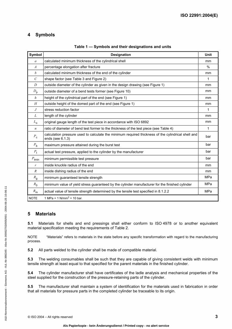
4 Symbols
Table 1 — Symbols and their designations and units
Symbol Designation Unit a calculated minimum thickness of the cylindrical shell mm A percentage elongation after fracture % b calculated minimum thickness of the end of the cylinder mm C shape factor (see Table 3 and Figure 2) 1 D outside diameter of the cylinder as given in the design drawing (see Figure 1) mm Dp outside diameter of a bend tests former (see Figure 10) mm
h height of the cylindrical part of the end (see Figure 1) mm H outside height of the domed part of the end (see Figure 1) mm J stress reduction factor 1 L length of the cylinder mm Lo original gauge length of the test piece in accordance with ISO 6892 mm
n ratio of diameter of bend test former to the thickness of the test piece (see Table 4) 1
Pc calculation pressure used to calculate the minimum required thickness of the cylindrical shell and ends (see 6.1.3) bar
Pb maximum pressure attained during the burst test bar
Pt actual test pressure, applied to the cylinder by the manufacturer bar
Ptmin minimum permissible test pressure bar
r inside knuckle radius of the end mm R inside dishing radius of the end mm Rg minimum guaranteed tensile strength MPa
R0 minimum value of yield stress guaranteed by the cylinder manufacturer for the finished cylinder MPa
Rm actual value of tensile strength determined by the tensile test specified in 8.1.2.2 MPa
NOTE 1 MPa = 1 N/mm2 = 10 bar.
5 Materials
5.1 Materials for shells and end pressings shall either conform to ISO 4978 or to another equivalent material specification meeting the requirements of Table 2.
NOTE “Materials” refers to materials in the state before any specific transformation with regard to the manufacturing process.
5.2 All parts welded to the cylinder shall be made of compatible material.
5.3 The welding consumables shall be such that they are capable of giving consistent welds with minimum tensile strength at least equal to that specified for the parent materials in the finished cylinder.
5.4 The cylinder manufacturer shall have certificates of the ladle analysis and mechanical properties of the steel supplied for the construction of the pressure-retaining parts of the cylinder.
5.5 The manufacturer shall maintain a system of identification for the materials used in fabrication in order that all materials for pressure parts in the completed cylinder be traceable to its origin.
BA178AF3EC677050DBAC9B8DA5349567ADC990EEFF93F3B562D565BBCCE551B04FB30348A9F905D2BEBE2EE710159EC8B560C0BF30F077189D3B68E26A9F3C8A6364EAF5157E4DFF4A2F011E10AD206AF0BD6437B2B1BD93F7746FD35D925920EF33
A&
I-N
orm
enab
on
nem
ent
- S
iem
ens
AG
- K
d.-
Nr.
9863
45 -
Ab
o-N
r.00
0027
03/0
05/0
01 -
200
4-06
-25
10:0
6:11
Als Papierkopie - kein Änderungsdienst / Printed copy - no alert service
ISO 22991:2004(E)
4 © ISO 2004 – All rights reserved
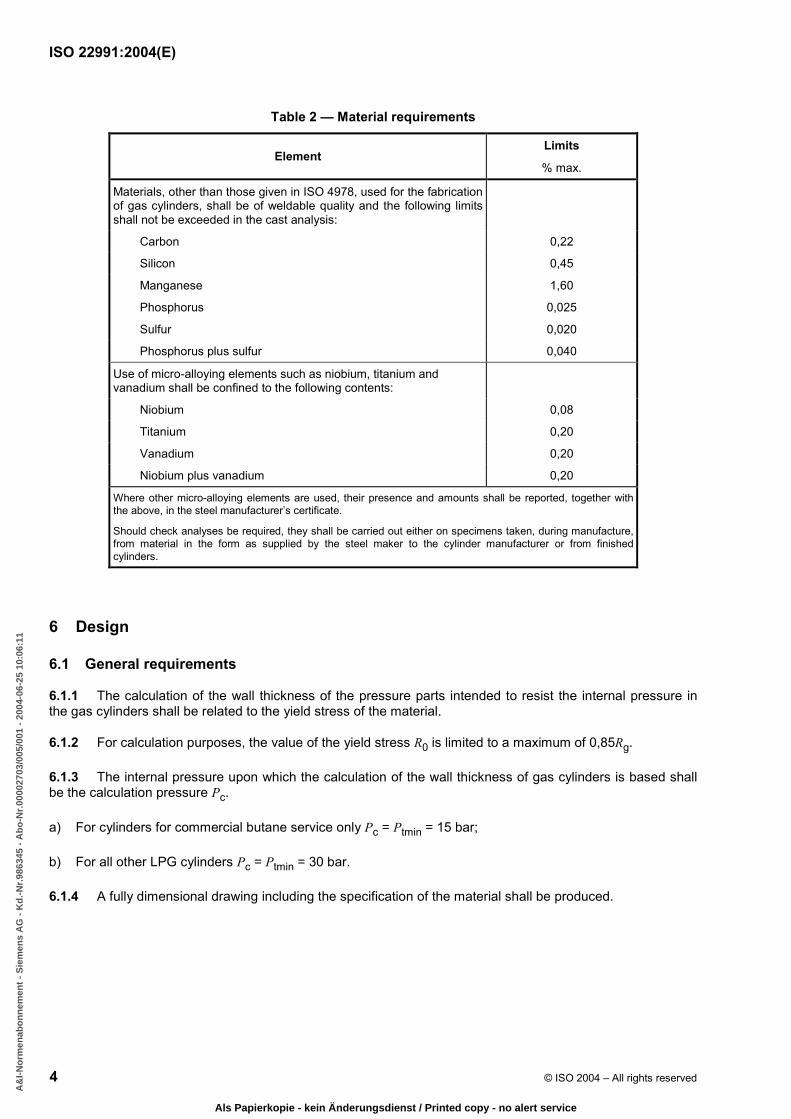
Table 2 — Material requirements
Element Limits
% max.
Materials, other than those given in ISO 4978, used for the fabrication of gas cylinders, shall be of weldable quality and the following limits shall not be exceeded in the cast analysis:
Carbon 0,22
Silicon 0,45
Manganese 1,60
Phosphorus 0,025
Sulfur 0,020
Phosphorus plus sulfur 0,040
Use of micro-alloying elements such as niobium, titanium and vanadium shall be confined to the following contents:
Niobium 0,08
Titanium 0,20
Vanadium 0,20
Niobium plus vanadium 0,20
Where other micro-alloying elements are used, their presence and amounts shall be reported, together with the above, in the steel manufacturer’s certificate.
Should check analyses be required, they shall be carried out either on specimens taken, during manufacture, from material in the form as supplied by the steel maker to the cylinder manufacturer or from finished cylinders.
6 Design
6.1 General requirements
6.1.1 The calculation of the wall thickness of the pressure parts intended to resist the internal pressure in the gas cylinders shall be related to the yield stress of the material.
6.1.2 For calculation purposes, the value of the yield stress R0 is limited to a maximum of 0,85Rg.
6.1.3 The internal pressure upon which the calculation of the wall thickness of gas cylinders is based shall be the calculation pressure Pc.
a) For cylinders for commercial butane service only Pc = Ptmin = 15 bar;
b) For all other LPG cylinders Pc = Ptmin = 30 bar.
6.1.4 A fully dimensional drawing including the specification of the material shall be produced.
BA178AF3EC677050DBAC9B8DA5349567ADC990EEFF93F3B562D565BBCCE551B04FB30348A9F905D2BEBE2EE710159EC8B560C0BF30F077189D3B68E26A9F3C8A6364EAF5157E4DFF4A2F011E10AD206AF0BD6437B2B1BD93F7746FD35D925920EF33
A&
I-N
orm
enab
on
nem
ent
- S
iem
ens
AG
- K
d.-
Nr.
9863
45 -
Ab
o-N
r.00
0027
03/0
05/0
01 -
200
4-06
-25
10:0
6:11
Als Papierkopie - kein Änderungsdienst / Printed copy - no alert service

ISO 22991:2004(E)
© ISO 2004 – All rights reserved 5
6.2 Calculation of cylindrical shell thickness
The wall thickness of the cylindrical shell shall be not less than that calculated using the formula:
o4
3
c20
c
R JP D
aP× ×
×=
+
for cylinders with a longitudinal weld: J = 0,9;
for cylinders without a longitudinal weld: J = 1,0.
In no case shall the actual thickness be less than that specified in 6.5.
6.3 Design of ends concave to pressure
6.3.1 Except as permitted by 6.4, the shape of ends of gas cylinders shall be such that the following conditions are fulfilled:
for torispherical ends: R u D; r W 0,1 D; h W 4b [see Figure 1a)];
for semi-ellipsoidal ends: H W 0,2 D; h W 4b [see Figure 1b)].
6.3.2 The wall thickness of the ends of gas cylinders shall be not less than that calculated using the formula:
oc
20 c4
3
RP D Cb
P×× ×
=+
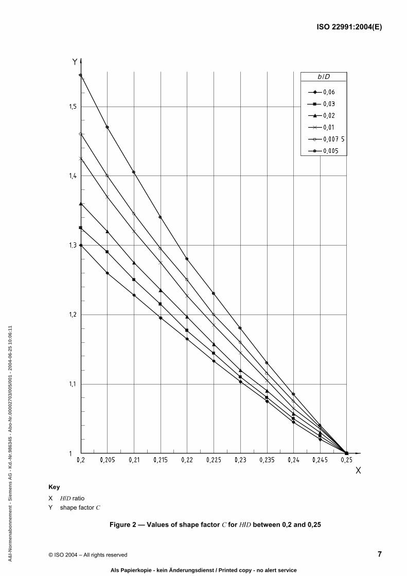
In this formula, C is a shape factor, the value of which depends on the ratio H/D.
The value of C shall be obtained from Table 3 and the graphs in Figure 2 and Figure 3.
The graph in Figure 2 details the value of C in relation to the ratio b/D.
BA178AF3EC677050DBAC9B8DA5349567ADC990EEFF93F3B562D565BBCCE551B04FB30348A9F905D2BEBE2EE710159EC8B560C0BF30F077189D3B68E26A9F3C8A6364EAF5157E4DFF4A2F011E10AD206AF0BD6437B2B1BD93F7746FD35D925920EF33
A&
I-N
orm
enab
on
nem
ent
- S
iem
ens
AG
- K
d.-
Nr.
9863
45 -
Ab
o-N
r.00
0027
03/0
05/0
01 -
200
4-06
-25
10:0
6:11
Als Papierkopie - kein Änderungsdienst / Printed copy - no alert service
ISO 22991:2004(E)
6 © ISO 2004 – All rights reserved
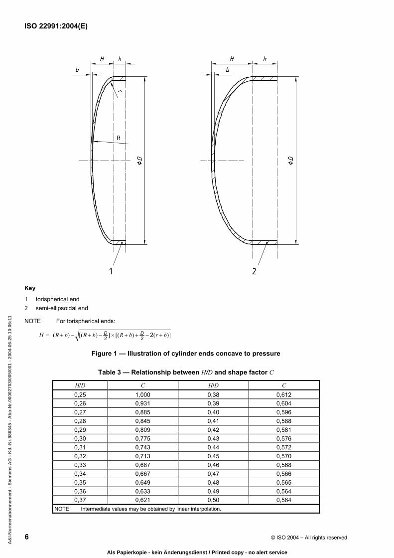
Key
1 torispherical end 2 semi-ellipsoidal end
NOTE For torispherical ends:
( ) [( ) ] [( ) ( )]2 2 2H R b R b R b r b= + − + − × + + − +D D
Figure 1 — Illustration of cylinder ends concave to pressure
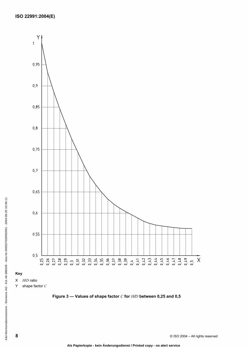
Table 3 — Relationship between H/D and shape factor C
H/D C H/D C 0,25 1,000 0,38 0,612 0,26 0,931 0,39 0,604 0,27 0,885 0,40 0,596 0,28 0,845 0,41 0,588 0,29 0,809 0,42 0,581 0,30 0,775 0,43 0,576 0,31 0,743 0,44 0,572 0,32 0,713 0,45 0,570 0,33 0,687 0,46 0,568 0,34 0,667 0,47 0,566 0,35 0,649 0,48 0,565 0,36 0,633 0,49 0,564 0,37 0,621 0,50 0,564
NOTE Intermediate values may be obtained by linear interpolation.
BA178AF3EC677050DBAC9B8DA5349567ADC990EEFF93F3B562D565BBCCE551B04FB30348A9F905D2BEBE2EE710159EC8B560C0BF30F077189D3B68E26A9F3C8A6364EAF5157E4DFF4A2F011E10AD206AF0BD6437B2B1BD93F7746FD35D925920EF33
A&
I-N
orm
enab
on
nem
ent
- S
iem
ens
AG
- K
d.-
Nr.
9863
45 -
Ab
o-N
r.00
0027
03/0
05/0
01 -
200
4-06
-25
10:0
6:11
Als Papierkopie - kein Änderungsdienst / Printed copy - no alert service
ISO 22991:2004(E)
© ISO 2004 – All rights reserved 7
Key
X H/D ratio Y shape factor C
Figure 2 — Values of shape factor C for H/D between 0,2 and 0,25
BA178AF3EC677050DBAC9B8DA5349567ADC990EEFF93F3B562D565BBCCE551B04FB30348A9F905D2BEBE2EE710159EC8B560C0BF30F077189D3B68E26A9F3C8A6364EAF5157E4DFF4A2F011E10AD206AF0BD6437B2B1BD93F7746FD35D925920EF33
A&
I-N
orm
enab
on
nem
ent
- S
iem
ens
AG
- K
d.-
Nr.
9863
45 -
Ab
o-N
r.00
0027
03/0
05/0
01 -
200
4-06
-25
10:0
6:11
Als Papierkopie - kein Änderungsdienst / Printed copy - no alert service
ISO 22991:2004(E)
8 © ISO 2004 – All rights reserved
Key
X H/D ratio Y shape factor C
Figure 3 — Values of shape factor C for H/D between 0,25 and 0,5
BA178AF3EC677050DBAC9B8DA5349567ADC990EEFF93F3B562D565BBCCE551B04FB30348A9F905D2BEBE2EE710159EC8B560C0BF30F077189D3B68E26A9F3C8A6364EAF5157E4DFF4A2F011E10AD206AF0BD6437B2B1BD93F7746FD35D925920EF33
A&
I-N
orm
enab
on
nem
ent
- S
iem
ens
AG
- K
d.-
Nr.
9863
45 -
Ab
o-N
r.00
0027
03/0
05/0
01 -
200
4-06
-25
10:0
6:11
Als Papierkopie - kein Änderungsdienst / Printed copy - no alert service

ISO 22991:2004(E)
© ISO 2004 – All rights reserved 9
6.4 Ends of other shapes
Ends of shapes other than those covered by 6.3 may be used provided that the adequacy of their design is demonstrated by fatigue testing in accordance with 8.6. For heads convex to pressure, the minimum head thickness shall be a minimum of 2 times that specified in 6.2.
6.5 Minimum wall thickness
6.5.1 The minimum wall thickness of the cylindrical shell, a, and of the end, b, shall be not less than the value derived from any of the following formulae:
for D < 100 mm:
amin = bmin = 1,1 mm (1)
for 100 mm u D u 150 mm:
amin = bmin = 1,1 + 0,008(D − 100) mm (2)
for D > 150 mm:
amin = bmin = (D/250) + 0,7 mm (3)
(with a minimum of 1,5 mm).
These formulae apply to cylindrical shells and ends irrespective of whether they are designed by calculation as specified in 6.2 and 6.3 or by testing as specified in 6.4. Apart from the requirements of 6.3, 6.4 and 6.5, any cylindrical part integral with an end shall, except as qualified by 6.5.2, also satisfy the requirements in 6.2 for the cylindrical shell.
6.5.2 The equation in 6.2 is not applicable where the length of the cylindrical portion of the cylinder, measured between the beginning of the domed parts of the two ends, is not more than 2 .bD In this case the wall thickness shall be not less than that of the domed part (see 6.3.2).
6.6 Design of openings
6.6.1 The location of all openings shall be restricted to one dished end of the cylinder.
6.6.2 Each opening in the cylinder shall be reinforced, either by a valve boss or pad, of weldable and compatible steel, securely attached by welding and so designed as to be of adequate strength and to result in no harmful stress concentrations. This shall be confirmed by design calculations or a fatigue test in accordance with 8.6.
6.6.3 If the leak-tightness between the valve and the cylinder is assured by a metallic seal (e.g. copper), a suitable internal valve boss can be fitted to the cylinder by a method which need not independently guarantee leak-tightness.
6.6.4 Unless otherwise specified, valve threads shall conform to a recognized specification e.g. ISO 10920 for the 25E thread or ISO 11116-1 for the 17E thread.
6.7 Valve protection
The design of the cylinder shall provide protection for valves against damage in order to avoid release of contents, unless otherwise protected for transportation, etc. in accordance with 7.6.
BA178AF3EC677050DBAC9B8DA5349567ADC990EEFF93F3B562D565BBCCE551B04FB30348A9F905D2BEBE2EE710159EC8B560C0BF30F077189D3B68E26A9F3C8A6364EAF5157E4DFF4A2F011E10AD206AF0BD6437B2B1BD93F7746FD35D925920EF33
A&
I-N
orm
enab
on
nem
ent
- S
iem
ens
AG
- K
d.-
Nr.
9863
45 -
Ab
o-N
r.00
0027
03/0
05/0
01 -
200
4-06
-25
10:0
6:11
Als Papierkopie - kein Änderungsdienst / Printed copy - no alert service
ISO 22991:2004(E)
10 © ISO 2004 – All rights reserved
7 Construction and workmanship
7.1 Welding qualification
7.1.1 The manufacturer, with the agreement of a competent body, before proceeding with the production of a given design of cylinder, shall approve the welding procedures to ISO 9956-3, welders to ISO 9606-1 and welding operators to ISO 14732, for all welding associated with the pressure envelope including the non-pressure-containing parts. Records of such approvals shall be retained by the manufacturer.
7.1.2 Welding procedure approval tests shall be made in such a manner that the welds shall be representative of those made in production.
7.1.3 Welders shall have passed the approval tests for the specific type of work and procedure concerned.
7.2 Plates and pressed parts
Before assembly, the pressure parts of the cylinders shall be visually examined for uniform quality and freedom from defects which may ultimately affect the cylinder integrity.
7.3 Welded joints
7.3.1 The welding of the longitudinal and circumferential joints shall be by a fully mechanized or semi-automatic or fully automatic process to provide consistent and reproducible quality of welds.
7.3.2 The longitudinal joint, of which there shall be no more than one, shall be the butt welded type.
7.3.3 Circumferential joints, of which there shall be no more than two, shall be butt welded, or butt welded with one member offset to form an integral backing strip, i.e. joggled (see Figure 4).
7.3.4 Before the cylinders are closed, longitudinal welds shall be visually examined from both sides in accordance with ISO 17637. Permanent backing strips shall not be used with longitudinal welds.
7.3.5 The fusion of the welded metal with the parent metal shall be smooth and free from overlapping, undercutting or abrupt irregularities. There shall be no cracks, notching or porous patches in the welded surface and the surface adjacent to the weld. The welded surface shall be regular and even without concavity. The excess thickness of the weld (bead height) shall not exceed one-fourth of the width of the weld.
7.3.6 Butt welds shall have full penetration.
7.3.7 Joggle butt welds shall have full root penetration verified by macro etch, bend testing and tensile testing.
7.4 Tolerances
7.4.1 Out of roundness
The out of roundness of the cylindrical shell shall be limited so that the difference between the maximum and the minimum outside diameter in the same cross section is not more than 1 % of the mean of these diameters, for two-piece cylinders, and 1,5 % for three-piece cylinders. The measurement shall not be taken over any of the welds but shall be taken adjacent to the welds.
7.4.2 Straightness
Unless otherwise shown on the manufacturer's drawing, the maximum deviation of the cylindrical part of the shell from a straight line shall not exceed 0,3 % of the cylindrical length.
BA178AF3EC677050DBAC9B8DA5349567ADC990EEFF93F3B562D565BBCCE551B04FB30348A9F905D2BEBE2EE710159EC8B560C0BF30F077189D3B68E26A9F3C8A6364EAF5157E4DFF4A2F011E10AD206AF0BD6437B2B1BD93F7746FD35D925920EF33
A&
I-N
orm
enab
on
nem
ent
- S
iem
ens
AG
- K
d.-
Nr.
9863
45 -
Ab
o-N
r.00
0027
03/0
05/0
01 -
200
4-06
-25
10:0
6:11
Als Papierkopie - kein Änderungsdienst / Printed copy - no alert service

ISO 22991:2004(E)
© ISO 2004 – All rights reserved 11
Key a Bevel optional. d Inside of cylinder to avoid sharp break. b As desired. e Thickness of metal which is offset. c Depth of offset = e1. e1 Thickness of metal which is not offset.
Figure 4 — Illustration of a typical joggled butt joint
7.4.3 Verticality
When the cylinder is standing on its base, deviation from vertical shall not exceed 25 mm per metre of length.
7.5 Non-pressure-containing attachments
7.5.1 Where non-pressure-containing attachments are to be attached to the cylinder by welding, such attachments shall be made of weldable and compatible steel (see 5.2).
7.5.2 Attachments shall be designed to permit inspection of welds, which shall be clear of longitudinal and circumferential joints, and so designed as to avoid trapping water.
7.5.3 Where a footring is fitted, it shall be of adequate strength to provide stability and be attached so that it does not prevent inspection of any pressure-containing welds. Any footring shall be suitably drained and the space enclosed by the footring suitably ventilated, e.g., by means of openings.
7.6 Valve protection
When the requirements of 6.7 are not met, then the manufacturer shall specify that the cylinders shall be conveyed in crates or cradles or shall be provided, during transportation, with some other effective valve protection, unless it can be demonstrated that the valve can withstand damage without product leakage.
7.7 Closure of openings
Where cylinders are supplied without the valve or safety device fitted, all openings shall be fitted with a plug of non-absorbent material to protect the thread and prevent ingress of moisture.
7.8 Heat treatment
7.8.1 Except as permitted under 7.8.4, cylinders shall be delivered in the heat treated (normalized or stress relieved) condition (see 3.2 and 3.3).
7.8.2 The cylinder manufacturer shall maintain records to indicate that the cylinders have been heat treated (normalized or stress relieved) after completion of all welding and to indicate the adequacy of the process of heat treatment.
BA178AF3EC677050DBAC9B8DA5349567ADC990EEFF93F3B562D565BBCCE551B04FB30348A9F905D2BEBE2EE710159EC8B560C0BF30F077189D3B68E26A9F3C8A6364EAF5157E4DFF4A2F011E10AD206AF0BD6437B2B1BD93F7746FD35D925920EF33
A&
I-N
orm
enab
on
nem
ent
- S
iem
ens
AG
- K
d.-
Nr.
9863
45 -
Ab
o-N
r.00
0027
03/0
05/0
01 -
200
4-06
-25
10:0
6:11
Als Papierkopie - kein Änderungsdienst / Printed copy - no alert service

ISO 22991:2004(E)
12 © ISO 2004 – All rights reserved
7.8.3 Localized heat treatment shall not be permitted.
7.8.4 Cylinders may be delivered that have not been heat treated (normalized or stress relieved) where the manufacturer complies with all the following requirements:
a) the cylinders shall be of three-piece construction;
b) ends shall be semi-ellipsoidal or torispherical in accordance with Figure 1, and pressing depth shall be limited such that:
0,26H bD− u (4)
and
8h bu (5)
c) the cylinders shall only be made from a fine grain steel with maximum grain size of 8, in the delivery condition, when tested in accordance with ISO 643;
d) three samples of each type shall be subjected to fatigue testing in accordance with 8.6.
Any subsequent change in design, material thickness, material specification or weld procedure shall require further fatigue testing.
8 Testing
8.1 Mechanical testing
8.1.1 General requirements
8.1.1.1 Where not covered by the requirements contained in this clause, the mechanical tests shall be carried out in accordance with the following documents:
a) parent material:
ISO 6892 in the case of the tensile test;
ISO 7438, as appropriate, in the case of the bend test, according to whether the thickness of the test-piece is 3 mm or above, or less than 3 mm;
b) welded test specimens tested in accordance with 8.1.2.
8.1.1.2 All the mechanical tests for checking the properties of the parent metal and welds of the pressure-containing shells of the gas cylinders shall be carried out on test specimens taken from finished cylinders.
8.1.2 Types of test and evaluation of test results
8.1.2.1 Tests
Each sample cylinder shall be subjected to the following tests.
a) For cylinders containing only circumferential welds (two-piece cylinders), one test specimen taken from the places shown in Figure 5.
BA178AF3EC677050DBAC9B8DA5349567ADC990EEFF93F3B562D565BBCCE551B04FB30348A9F905D2BEBE2EE710159EC8B560C0BF30F077189D3B68E26A9F3C8A6364EAF5157E4DFF4A2F011E10AD206AF0BD6437B2B1BD93F7746FD35D925920EF33
A&
I-N
orm
enab
on
nem
ent
- S
iem
ens
AG
- K
d.-
Nr.
9863
45 -
Ab
o-N
r.00
0027
03/0
05/0
01 -
200
4-06
-25
10:0
6:11
Als Papierkopie - kein Änderungsdienst / Printed copy - no alert service
ISO 22991:2004(E)
© ISO 2004 – All rights reserved 13
1 tensile test (in accordance with ISO 5178), parent metal in the geometric longitudinal direction of the cylinder (1), or, if it is not possible, in the circumferential direction or the centre of one dished end;
1 tensile test (in accordance with ISO 4136), perpendicular to the circumferential weld (2);
1 bend test (in accordance with ISO 7438), on the topside of the circumferential weld (3);
1 bend test (in accordance with ISO 7438), on the underside of the circumferential weld (4);
1 macro test (in accordance with ISO 17639), on a randomly selected location on the circumferential weld.
Test pieces which are not sufficiently flat shall be flattened by cold pressing. In all bend test specimens containing a weld, the weld shall be machined flush with the parent metal surface.
b) For cylinders with longitudinal and circumferential welds (three-piece cylinders), on test specimens taken from the places shown in Figure 6.
1 tensile test (in accordance with ISO 5178), parent metal of cylindrical part in the longitudinal direction (1), or, if this is not possible, in a circumferential direction;
1 tensile test (in accordance with ISO 5178), parent metal from one dished end (2);
1 tensile test (in accordance with ISO 4136), perpendicular to the longitudinal weld (3);
1 tensile test (in accordance with ISO 4136), perpendicular to the circumferential weld (4);
1 bend test (in accordance with ISO 7438), on the topside of longitudinal weld (5);
1 bend test (in accordance with ISO 7438), on the underside of the longitudinal weld (6);
1 bend test (in accordance with ISO 7438), on the topside of the circumferential weld (7);
1 bend test (in accordance with ISO 7438), on the underside of the circumferential weld (8);
1 macro test (in accordance with ISO 17639), on a randomly selected location on the circumferential weld.
Test pieces which are not sufficiently flat shall be flattened by cold pressing. In all bend test specimens containing a weld, the weld shall be machined flush with the parent metal surface.
The welding of the valve boss shall be checked at least by radiographic or macro examination in accordance with 8.4. In addition one sample from each welding process of non-pressure-containing attachments shall be checked to ensure that the heat affected zone does not extend to more than 40 % of the wall thickness of the pressure-containing envelope.
8.1.2.2 Tensile test
8.1.2.2.1 Tensile test on parent metal
8.1.2.2.1.1 The procedure for carrying out the tensile test is that given in the appropriate International Standards in accordance with 8.1.1.1. The two faces of the test specimen representing the inside and outside walls of the cylinder respectively shall not be machined.
8.1.2.2.1.2 The values obtained for yield stress, tensile strength and elongation shall be not less than those guaranteed by the cylinder manufacturer and in no case less than those given in the material specification.
BA178AF3EC677050DBAC9B8DA5349567ADC990EEFF93F3B562D565BBCCE551B04FB30348A9F905D2BEBE2EE710159EC8B560C0BF30F077189D3B68E26A9F3C8A6364EAF5157E4DFF4A2F011E10AD206AF0BD6437B2B1BD93F7746FD35D925920EF33
A&
I-N
orm
enab
on
nem
ent
- S
iem
ens
AG
- K
d.-
Nr.
9863
45 -
Ab
o-N
r.00
0027
03/0
05/0
01 -
200
4-06
-25
10:0
6:11
Als Papierkopie - kein Änderungsdienst / Printed copy - no alert service
ISO 22991:2004(E)
14 © ISO 2004 – All rights reserved
8.1.2.2.2 Tensile test on welds
8.1.2.2.2.1 The tensile test perpendicular to the weld (see ISO 4136) shall be carried out on a test specimen having a reduced cross section 25 mm in width for a length extending up to 15 mm beyond the edges of the weld (see Figure 7). Beyond this central part the width of the test specimen shall increase progressively.
8.1.2.2.2.2 The tensile strength value obtained, Rm, shall be not less than that guaranteed by the cylinder manufacturer, Rg, and in no case less than those given in the material specification, irrespective of where the fracture occurs in the cross section of the central part of the test specimen.
8.1.2.3 Bend test
8.1.2.3.1 The procedure for carrying out a bend test is given in ISO 7438. The bend test specimen shall be 25 mm in width. The mandrel shall be placed in the centre of the weld while the test is being performed (see Figure 8).
8.1.2.3.2 Cracks shall not appear in the test specimen when it is bent around a mandrel such that it has been bent through 180° (see Figure 8).
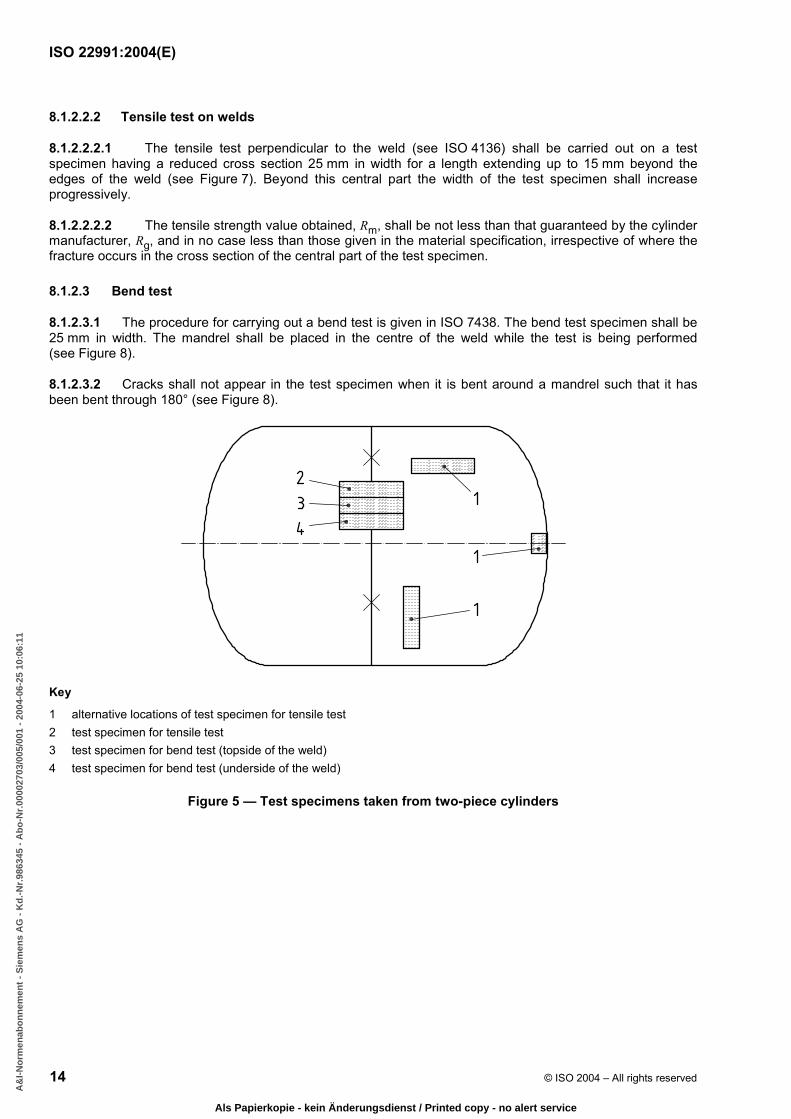
Key
1 alternative locations of test specimen for tensile test 2 test specimen for tensile test 3 test specimen for bend test (topside of the weld) 4 test specimen for bend test (underside of the weld)
Figure 5 — Test specimens taken from two-piece cylinders
BA178AF3EC677050DBAC9B8DA5349567ADC990EEFF93F3B562D565BBCCE551B04FB30348A9F905D2BEBE2EE710159EC8B560C0BF30F077189D3B68E26A9F3C8A6364EAF5157E4DFF4A2F011E10AD206AF0BD6437B2B1BD93F7746FD35D925920EF33
A&
I-N
orm
enab
on
nem
ent
- S
iem
ens
AG
- K
d.-
Nr.
9863
45 -
Ab
o-N
r.00
0027
03/0
05/0
01 -
200
4-06
-25
10:0
6:11
Als Papierkopie - kein Änderungsdienst / Printed copy - no alert service

ISO 22991:2004(E)
© ISO 2004 – All rights reserved 15
Key
1 alternative locations of test specimens for tensile test 2 test specimen for tensile test 3 test specimen for bend test (topside of the weld) 4 test specimen for bend test (underside of the weld)
Figure 6 — Test specimens taken from three piece cylinders
Dimensions in millimetres
Key
1 weld
Figure 7 — Test specimen for tensile test perpendicular to the weld
BA178AF3EC677050DBAC9B8DA5349567ADC990EEFF93F3B562D565BBCCE551B04FB30348A9F905D2BEBE2EE710159EC8B560C0BF30F077189D3B68E26A9F3C8A6364EAF5157E4DFF4A2F011E10AD206AF0BD6437B2B1BD93F7746FD35D925920EF33
A&
I-N
orm
enab
on
nem
ent
- S
iem
ens
AG
- K
d.-
Nr.
9863
45 -
Ab
o-N
r.00
0027
03/0
05/0
01 -
200
4-06
-25
10:0
6:11
Als Papierkopie - kein Änderungsdienst / Printed copy - no alert service

ISO 22991:2004(E)
16 © ISO 2004 – All rights reserved
Dimensions in millimetres
a) Dimensions of test specimen
b) Transverse guided bend test specimen preparation
c) Illustration of bend test Key
1 butt weld specimen 2 joggled joint weld specimen 3 weld dressed flush 4 joggled portion to be removed
Figure 8 — Bend tests
BA178AF3EC677050DBAC9B8DA5349567ADC990EEFF93F3B562D565BBCCE551B04FB30348A9F905D2BEBE2EE710159EC8B560C0BF30F077189D3B68E26A9F3C8A6364EAF5157E4DFF4A2F011E10AD206AF0BD6437B2B1BD93F7746FD35D925920EF33
A&
I-N
orm
enab
on
nem
ent
- S
iem
ens
AG
- K
d.-
Nr.
9863
45 -
Ab
o-N
r.00
0027
03/0
05/0
01 -
200
4-06
-25
10:0
6:11
Als Papierkopie - kein Änderungsdienst / Printed copy - no alert service

ISO 22991:2004(E)
© ISO 2004 – All rights reserved 17
Table 4 — Ratio of mandrel diameter and test piece thickness
Actual measured tensile strength
Rm MPa Value of n
u 440 2
> 440 u 520 3
> 520 4
8.1.2.3.3 The ratio n between the diameter of the mandrel, Dp, and the thickness of the test specimen, a, shall not exceed the values given in the Table 3.
8.2 Burst test under hydraulic pressure
8.2.1 Test conditions
8.2.1.1 If it is proposed to apply markings (in accordance with Clause 11) on the section of the cylinder subjected to pressure, then cylinders to be tested shall be similarly marked.
8.2.1.2 The burst test under hydraulic pressure shall be carried out with equipment which enables the pressure to be increased gradually until the cylinder bursts. The pressure at which the cylinder bursts shall be recorded.
8.2.2 Interpretation of test
The criteria adopted for the interpretation of the burst test are as follows:
a) volumetric expansion of the cylinder; this equals:
the volume of water used between the time when the pressure starts to rise and at the time of bursting or
the difference between the volume of the cylinder at the beginning and the end of the test (see 8.2.3.2);
b) examination of the tear and the shape of its edges (see 8.2.3.3).
8.2.3 Minimum test requirements
8.2.3.1 Bursting pressure
The measured bursting pressure Pb shall not under any circumstances be less than 225 % of the calculation pressure Pc, and not less than 50 bar.
8.2.3.2 Volumetric expansion
The ratio of the volumetric expansion of the cylinder to its initial volume shall be greater than or equal to:
20 %, if the length of the cylinder (length of the pressure envelope including the valve boss/neck ring) is greater than the diameter D;
17 %, if the length of the cylinder (length of the pressure envelope including the valve boss/neck ring) is equal to or less than the diameter D.
BA178AF3EC677050DBAC9B8DA5349567ADC990EEFF93F3B562D565BBCCE551B04FB30348A9F905D2BEBE2EE710159EC8B560C0BF30F077189D3B68E26A9F3C8A6364EAF5157E4DFF4A2F011E10AD206AF0BD6437B2B1BD93F7746FD35D925920EF33
A&
I-N
orm
enab
on
nem
ent
- S
iem
ens
AG
- K
d.-
Nr.
9863
45 -
Ab
o-N
r.00
0027
03/0
05/0
01 -
200
4-06
-25
10:0
6:11
Als Papierkopie - kein Änderungsdienst / Printed copy - no alert service

ISO 22991:2004(E)
18 © ISO 2004 – All rights reserved
8.2.3.3 Type of fracture
The fracture shall not initiate in a weld.
The main fracture shall not show any brittleness, i.e. the edges of the fracture shall not be radial but shall be at an angle to a diametrical plane and display a reduction of area throughout their thickness.
The fracture shall not reveal a visible defect in the metal, e.g. lamination.
The burst test shall not cause any fragmentation of the cylinder.
8.3 Pressure test
8.3.1 The pressurization medium shall normally be a liquid. A gas may be used provided that appropriate safety precautions are taken.
8.3.2 The minimum test pressure to be applied shall be as specified in 6.1.3. For butane cylinders only, the test pressure may be higher than the one shown in 6.1.3. In this case, the membrane stress within the wall of the cylinder shall not exceed 90 % of the minimum yield stress of the material (as stated in the material standard) during the test.
8.3.3 The pressure in the cylinder shall increase gradually until the test pressure is reached.
8.3.4 The cylinder shall remain under pressure for at least 30 s in order to make it possible to establish that no leak can be observed.
8.3.5 After the test the cylinder shall show no signs of permanent deformation.
8.3.6 Any cylinder tested which does not pass the test shall be rejected.
8.4 Radiographic and macro examination
8.4.1 Radiographic examination
8.4.1.1 General
Radiographic examination shall conform to the techniques specified in 8.4.1.3 to 8.4.1.5.
8.4.1.2 Radiographic requirements
a) Radiography shall be carried out on the circumferential and longitudinal welds (see Figures 9 and 10) of the first production cylinder after a change in type or size of cylinder or the welding procedure (including machine setting), or after a break in production exceeding 4 h.
Exception: in the case of cylinders less than 250 mm outside diameter, radiography of joggle joints circumferential welds may be replaced by two macro examinations (see 8.4.2) one of which shall be at the plane of the stop/start area and the other on the opposite side of the cylinder.
b) In addition to the requirements of a) for cylinders with longitudinal welds, one cylinder out of every 250 production cylinders shall have the junction of the longitudinal and circumferential welds radiographed as indicated in Figure 10.
c) Where more than one welding machine is used for production, the above procedures shall apply to all such machines.
BA178AF3EC677050DBAC9B8DA5349567ADC990EEFF93F3B562D565BBCCE551B04FB30348A9F905D2BEBE2EE710159EC8B560C0BF30F077189D3B68E26A9F3C8A6364EAF5157E4DFF4A2F011E10AD206AF0BD6437B2B1BD93F7746FD35D925920EF33
A&
I-N
orm
enab
on
nem
ent
- S
iem
ens
AG
- K
d.-
Nr.
9863
45 -
Ab
o-N
r.00
0027
03/0
05/0
01 -
200
4-06
-25
10:0
6:11
Als Papierkopie - kein Änderungsdienst / Printed copy - no alert service
ISO 22991:2004(E)
© ISO 2004 – All rights reserved 19
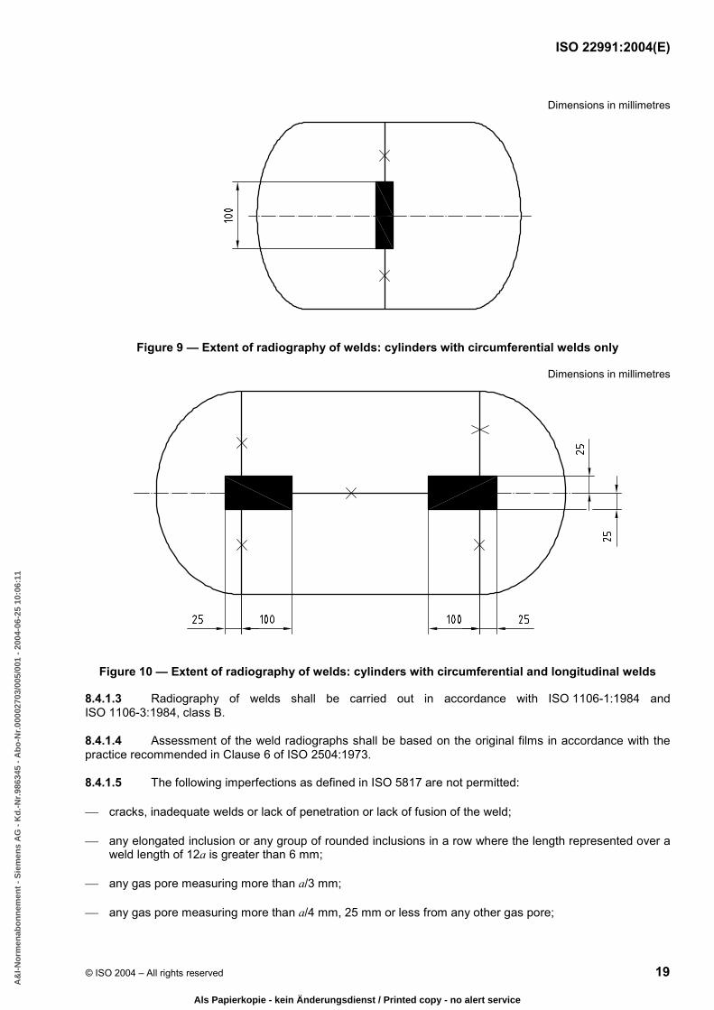
Dimensions in millimetres
Figure 9 — Extent of radiography of welds: cylinders with circumferential welds only
Dimensions in millimetres
Figure 10 — Extent of radiography of welds: cylinders with circumferential and longitudinal welds
8.4.1.3 Radiography of welds shall be carried out in accordance with ISO 1106-1:1984 and ISO 1106-3:1984, class B.
8.4.1.4 Assessment of the weld radiographs shall be based on the original films in accordance with the practice recommended in Clause 6 of ISO 2504:1973.
8.4.1.5 The following imperfections as defined in ISO 5817 are not permitted:
cracks, inadequate welds or lack of penetration or lack of fusion of the weld;
any elongated inclusion or any group of rounded inclusions in a row where the length represented over a weld length of 12a is greater than 6 mm;
any gas pore measuring more than a/3 mm;
any gas pore measuring more than a/4 mm, 25 mm or less from any other gas pore;
BA178AF3EC677050DBAC9B8DA5349567ADC990EEFF93F3B562D565BBCCE551B04FB30348A9F905D2BEBE2EE710159EC8B560C0BF30F077189D3B68E26A9F3C8A6364EAF5157E4DFF4A2F011E10AD206AF0BD6437B2B1BD93F7746FD35D925920EF33
A&
I-N
orm
enab
on
nem
ent
- S
iem
ens
AG
- K
d.-
Nr.
9863
45 -
Ab
o-N
r.00
0027
03/0
05/0
01 -
200
4-06
-25
10:0
6:11
Als Papierkopie - kein Änderungsdienst / Printed copy - no alert service
ISO 22991:2004(E)
20 © ISO 2004 – All rights reserved
gas pores over any 100 mm length, where the total area, in square millimetres, of all the figures is greater than 2a.
8.4.2 Macro examination
The macro examination, carried out in accordance with ISO 17639 of a full transverse section of the welds shall show complete fusion and complete penetration as specified in 8.4.1.5. In case of doubt, a microscopic examination of the suspect area shall be made.
8.4.3 Examination of valve boss/neck ring welding
For the examination of the valve boss/neck ring welding, radiographic or macro examination shall be carried out at sampling rates and on samples taken from cylinders corresponding to non-destructive tests as specified in 9.2.
8.4.4 Examination of welding non-pressure-containing attachments
For the examination of welding of non-pressure-containing attachments, radiographic or macro examinations shall be carried out on at least one cylinder out of every thousand production cylinders. The examination may be carried out on samples taken from cylinders corresponding to non-destructive tests specified in 9.2.
8.4.5 Unacceptable defects on radiographic or macro examination
Should any of the radiographic or macro examinations show any unacceptable defects, production shall be stopped and every cylinder welded since the preceding acceptable radiographic or macro examination shall be set aside until it is demonstrated that these cylinders are satisfactory either by radiographic or macro or other appropriate means. Production shall not be restarted until the cause of the defect has been established and rectified, and the starting up test procedure as specified in 8.4.1.2 a) has been repeated.
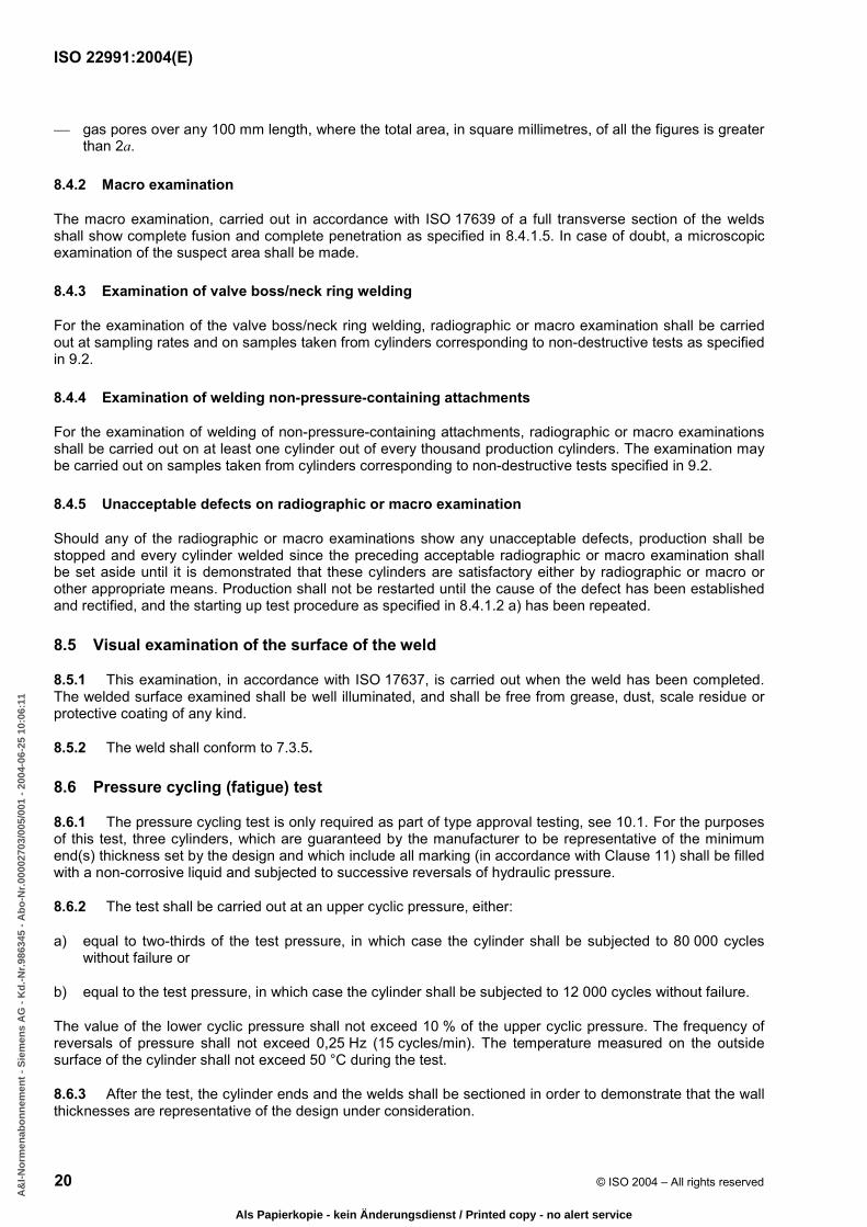
8.5 Visual examination of the surface of the weld
8.5.1 This examination, in accordance with ISO 17637, is carried out when the weld has been completed. The welded surface examined shall be well illuminated, and shall be free from grease, dust, scale residue or protective coating of any kind.
8.5.2 The weld shall conform to 7.3.5.
8.6 Pressure cycling (fatigue) test
8.6.1 The pressure cycling test is only required as part of type approval testing, see 10.1. For the purposes of this test, three cylinders, which are guaranteed by the manufacturer to be representative of the minimum end(s) thickness set by the design and which include all marking (in accordance with Clause 11) shall be filled with a non-corrosive liquid and subjected to successive reversals of hydraulic pressure.
8.6.2 The test shall be carried out at an upper cyclic pressure, either:
a) equal to two-thirds of the test pressure, in which case the cylinder shall be subjected to 80 000 cycles without failure or
b) equal to the test pressure, in which case the cylinder shall be subjected to 12 000 cycles without failure.
The value of the lower cyclic pressure shall not exceed 10 % of the upper cyclic pressure. The frequency of reversals of pressure shall not exceed 0,25 Hz (15 cycles/min). The temperature measured on the outside surface of the cylinder shall not exceed 50 °C during the test.
8.6.3 After the test, the cylinder ends and the welds shall be sectioned in order to demonstrate that the wall thicknesses are representative of the design under consideration.
BA178AF3EC677050DBAC9B8DA5349567ADC990EEFF93F3B562D565BBCCE551B04FB30348A9F905D2BEBE2EE710159EC8B560C0BF30F077189D3B68E26A9F3C8A6364EAF5157E4DFF4A2F011E10AD206AF0BD6437B2B1BD93F7746FD35D925920EF33
A&
I-N
orm
enab
on
nem
ent
- S
iem
ens
AG
- K
d.-
Nr.
9863
45 -
Ab
o-N
r.00
0027
03/0
05/0
01 -
200
4-06
-25
10:0
6:11
Als Papierkopie - kein Änderungsdienst / Printed copy - no alert service

ISO 22991:2004(E)
© ISO 2004 – All rights reserved 21
9 Acceptance procedure
9.1 General
9.1.1 All acceptance testing as required by this clause shall be carried out on finished production cylinders, prior to surface treatment.
9.1.2 All cylinders shall be subject to a pressure test as specified in 8.3 and visual examination of the surface of the welds as specified in 8.5.
9.1.3 Radiographic examination or macro examination shall be carried out as specified in 8.4.
9.1.4 Mechanical testing as specified in 8.1 and burst testing as specified in 8.2 shall be carried out on samples as specified in 9.2. The wall thickness at the thinnest point shall be measured and the stress shall be calculated on an adequate sample of cylinders.
9.2 Batch testing
9.2.1 Batch
A batch shall consist of finished cylinders made consecutively by the same manufacturer using the same manufacturing technique, to the same design, size and material specifications on the same type of automatic welding machines and subject to the same heat treatment conditions.
NOTE In this context “consecutively” need not imply continuous production.
9.2.2 Inspection lots
For acceptance purposes the batch shall be divided into inspection lots not exceeding 1 000 cylinders. For selection of sample cylinders for either burst or mechanical tests, each lot is subdivided into sub-lots of 250 cylinders during the first 3 000 cylinders of a batch and thereafter sub-lots of 500 cylinders or 1 000 cylinders, depending on cylinder size (see Figure 11).
9.2.3 Rate of sampling
9.2.3.1 General
Where a batch contains material from more than one cast, the manufacturer shall arrange for samples tested to represent each cast of material used. The reduced rate of sampling for large volume manufacture (above 3 000 cylinders) is subject to written agreement with a competent body once the manufacturer can demonstrate that the batch production test results and manufacturing processes are consistently reliable without any major interruption of manufacture. A chart illustrating the rate of sampling is given in Figure 11.
Except as permitted by 9.2.4, the samples taken for “mechanical or burst test” shall be alternated between the mechanical and burst tests.
BA178AF3EC677050DBAC9B8DA5349567ADC990EEFF93F3B562D565BBCCE551B04FB30348A9F905D2BEBE2EE710159EC8B560C0BF30F077189D3B68E26A9F3C8A6364EAF5157E4DFF4A2F011E10AD206AF0BD6437B2B1BD93F7746FD35D925920EF33
A&
I-N
orm
enab
on
nem
ent
- S
iem
ens
AG
- K
d.-
Nr.
9863
45 -
Ab
o-N
r.00
0027
03/0
05/0
01 -
200
4-06
-25
10:0
6:11
Als Papierkopie - kein Änderungsdienst / Printed copy - no alert service

ISO 22991:2004(E)
22 © ISO 2004 – All rights reserved
a For cylinders of volume u 35 l. b For cylinders of volume > 35 l.
Size of lot/sub-lot
Symbol No. of cylinders
Type of tests
250
2 one subjected to a burst test and one subjected to a mechanical test
250
1 one subjected to a burst test or to a mechanical test
500
2 one subjected to a burst test and one subjected to a mechanical test
500
1 one subjected to a burst test or to a mechanical test
1 000
2 one subjected to a burst test and one subjected to a mechanical test
NOTE Cylinders required by 9.2.2 to be subject to mechanical tests, and which have a water capacity less than 6,5 l and a burst pressure greater than 100 bar, may, at the manufacturer's discretion, be subjected to the alternative burst test.
Figure 11 — Inspection lots
9.2.3.2 Quantity less than or equal to 3 000 cylinders
9.2.3.2.1 From the first 250 cylinders or less in each inspection lot, representative cylinders shall be taken at random, one for the burst test and one for mechanical tests.
9.2.3.2.2 From each subsequent group of 250 cylinders or less in the inspection lot, one representative cylinder shall be taken at random for either a burst test or mechanical tests.
9.2.3.3 Quantity over 3 000 cylinders
9.2.3.3.1 For less than or equal to 35 l capacity, for the first 3 000 cylinders in the batch, representative cylinders shall be taken as specified in 9.2.3.2. From each inspection lot remaining, representative cylinders shall be taken at random, one for the burst test and one for mechanical tests.
BA178AF3EC677050DBAC9B8DA5349567ADC990EEFF93F3B562D565BBCCE551B04FB30348A9F905D2BEBE2EE710159EC8B560C0BF30F077189D3B68E26A9F3C8A6364EAF5157E4DFF4A2F011E10AD206AF0BD6437B2B1BD93F7746FD35D925920EF33
A&
I-N
orm
enab
on
nem
ent
- S
iem
ens
AG
- K
d.-
Nr.
9863
45 -
Ab
o-N
r.00
0027
03/0
05/0
01 -
200
4-06
-25
10:0
6:11
Als Papierkopie - kein Änderungsdienst / Printed copy - no alert service

ISO 22991:2004(E)
© ISO 2004 – All rights reserved 23
9.2.3.3.2 For greater than 35 l capacity, for the first 3 000 cylinders in the batch, representative cylinders shall be taken as specified in 9.2.3.2. From the first 500 cylinders or less in each inspection lot remaining, representative cylinders shall be taken at random, one for the burst test and one for mechanical tests. From the remaining 500 cylinders or less in such inspection lots, one representative cylinder shall be taken at random for either a burst test or mechanical tests.
9.2.4 For cylinders with a water capacity of less than 6,5 l and having a burst pressure greater than 100 bar. Those cylinders required to be subjected to mechanical tests, may, at the manufacturer's discretion, be subjected to the alternative burst test.
9.3 Failure to meet batch test requirements
9.3.1 In the event of failure to meet batch test requirements, retesting shall be carried out as specified in 9.3.2.
9.3.2 If there is evidence of a fault in carrying out the mechanical tests, or of an error of measurement, a second test on the same cylinder shall be performed. If the result of this test is satisfactory, the first test shall be ignored.
9.3.3 If the test has been carried out satisfactorily, the procedure specified in 9.3.3.1 or 9.3.3.2 shall be followed.
9.3.3.1 In the event of a single cylinder failing the initial mechanical or burst test, retesting of both mechanical and burst properties shall be made as shown in Table 5, the retest cylinders being taken at random from the same sub-lot.
Table 5 — Batch retest requirements
Inspection sub-lot size Failure Retest
u 250 1M 2M + 1B
u 250 1B 2B + 1M
> 250 1M 2M + 2B
> 250 1B 1M + 4B
NOTE “M” denotes mechanical test and “B” denotes burst test.
9.3.3.2 In the event of more than one cylinder failing the initial tests or one or more cylinders failing the retest specified in 9.3.3.1, the batch shall be rejected. In the case of heat treated cylinders, if the manufacturer:
a) re-heat treats the rejected batch or
b) repairs any weld defects and re-heat treats the batch, then the batch shall be resubmitted as a new batch as specified in 9.2.
In the case of non-heat treated cylinders, heat treatment shall only be applied if further type approval tests are carried out and the weld procedures are qualified for the heat treated condition.
10 Technical requirements for type approval
10.1 The manufacturer shall make available a batch of at least 50 cylinders of each type, from which the competent body shall select cylinders for test as follows:
BA178AF3EC677050DBAC9B8DA5349567ADC990EEFF93F3B562D565BBCCE551B04FB30348A9F905D2BEBE2EE710159EC8B560C0BF30F077189D3B68E26A9F3C8A6364EAF5157E4DFF4A2F011E10AD206AF0BD6437B2B1BD93F7746FD35D925920EF33
A&
I-N
orm
enab
on
nem
ent
- S
iem
ens
AG
- K
d.-
Nr.
9863
45 -
Ab
o-N
r.00
0027
03/0
05/0
01 -
200
4-06
-25
10:0
6:11
Als Papierkopie - kein Änderungsdienst / Printed copy - no alert service
ISO 22991:2004(E)
24 © ISO 2004 – All rights reserved
a) when so required by 6.4, 6.6.2, 7.8.4 d) or clause 11, a pressure cycling (fatigue) test as specified in 8.6: 3 cylinders;
b) mechanical tests as specified in 8.1: 2 cylinders;
c) a burst test as specified in 8.2: 2 cylinders.
From these cylinders, two shall have radiographic/macro tests as specified 8.4.1.3 to 8.4.1.5 and 8.4.2 respectively.
10.2 Different designs of cylinder shall be considered to be of the type within the following limitations:
a) two-piece cylinders that are of the same diameter, length and thickness, equipped with the same openings and manufactured using the same manufacturing techniques, and material specifications and on the same type of mechanized or automatic welding machines and subject to the same heat treatment conditions;
b) three-piece cylinders of the same diameter and thickness, equipped with the same openings manufactured as detailed in a) except that they can differ in length within the following limits:
the length of the cylindrical shell is not less than three times the outside diameter;
the length of the cylindrical shell is not more than 1,5 times the length of the cylindrical shell of the cylinders tested.
11 Marking
Each cylinder shall be permanently and legibly marked on a nameplate or other appropriate permanently attached non-pressure part, in accordance with ISO 13769, with the additional marks as detailed in Annex A. Where marking is on the ends of cylinders it shall be demonstrated in the fatigue and burst test that failure does not initiate in the markings and the markings are legible. Any limitation on the LPG to be put into the cylinder shall be permanently marked.
12 Certification
Each batch of cylinders shall be covered by a certificate to the effect that the cylinders meet the requirements of this International Standard, in all respects. A typical example of a certificate is given in Annex B.
BA178AF3EC677050DBAC9B8DA5349567ADC990EEFF93F3B562D565BBCCE551B04FB30348A9F905D2BEBE2EE710159EC8B560C0BF30F077189D3B68E26A9F3C8A6364EAF5157E4DFF4A2F011E10AD206AF0BD6437B2B1BD93F7746FD35D925920EF33
A&
I-N
orm
enab
on
nem
ent
- S
iem
ens
AG
- K
d.-
Nr.
9863
45 -
Ab
o-N
r.00
0027
03/0
05/0
01 -
200
4-06
-25
10:0
6:11
Als Papierkopie - kein Änderungsdienst / Printed copy - no alert service
ISO 22991:2004(E)
© ISO 2004 – All rights reserved 25
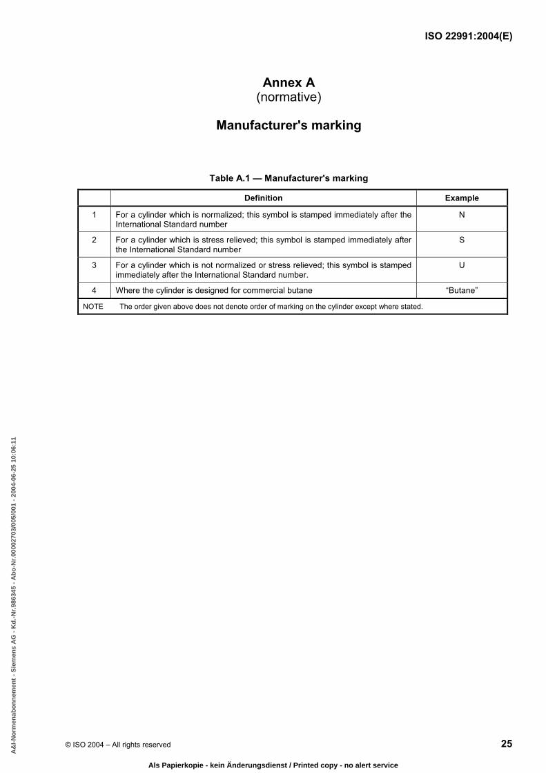
Annex A (normative)
Manufacturer's marking
Table A.1 — Manufacturer's marking
Definition Example
1 For a cylinder which is normalized; this symbol is stamped immediately after the International Standard number
N
2 For a cylinder which is stress relieved; this symbol is stamped immediately after the International Standard number
S
3 For a cylinder which is not normalized or stress relieved; this symbol is stamped immediately after the International Standard number.
U
4 Where the cylinder is designed for commercial butane “Butane”
NOTE The order given above does not denote order of marking on the cylinder except where stated.
BA178AF3EC677050DBAC9B8DA5349567ADC990EEFF93F3B562D565BBCCE551B04FB30348A9F905D2BEBE2EE710159EC8B560C0BF30F077189D3B68E26A9F3C8A6364EAF5157E4DFF4A2F011E10AD206AF0BD6437B2B1BD93F7746FD35D925920EF33
A&
I-N
orm
enab
on
nem
ent
- S
iem
ens
AG
- K
d.-
Nr.
9863
45 -
Ab
o-N
r.00
0027
03/0
05/0
01 -
200
4-06
-25
10:0
6:11
Als Papierkopie - kein Änderungsdienst / Printed copy - no alert service

ISO 22991:2004(E)
26 © ISO 2004 – All rights reserved
Annex B (informative)
Examples of type approval and production test certificates
B.1 Model type approval certificate
Issued by ................................... (Relevant Authority) .................................... on the basis of
..................................................................................................................................................
applying ISO 22991 .................................................................................................................
concerning WELDED, STEEL GAS CYLINDERS FOR LPG
_________________________________________________________________________
Approval No. ....................................................................... Date ..........................................
Type of cylinder …(Description of the family of cylinders which has received type approval)...
Pt ....................................... D ........................... Dp ...................... a ............ b .....................
Lo ...................................... Lmax
Manufacturer or agent ........................ (Name and address of manufacturer or its agent) ....
..................................................................................................................................................
..................................................................................................................................................
..................................................................................................................................................
Type approval mark .................................................................................................................
Details of the results of the examination of the type for type approval and the main features of the type are attached.
All information may be obtained from ............. (Name and address of the approving body) ..
..................................................................................................................................................
..................................................................................................................................................
..................................................................................................................................................
Date .................................................... Place .........................................................................
Signature ..............................................................
BA178AF3EC677050DBAC9B8DA5349567ADC990EEFF93F3B562D565BBCCE551B04FB30348A9F905D2BEBE2EE710159EC8B560C0BF30F077189D3B68E26A9F3C8A6364EAF5157E4DFF4A2F011E10AD206AF0BD6437B2B1BD93F7746FD35D925920EF33
A&
I-N
orm
enab
on
nem
ent
- S
iem
ens
AG
- K
d.-
Nr.
9863
45 -
Ab
o-N
r.00
0027
03/0
05/0
01 -
200
4-06
-25
10:0
6:11
Als Papierkopie - kein Änderungsdienst / Printed copy - no alert service

ISO 22991:2004(E)
© ISO 2004 – All rights reserved 27
Comments for use with type approval certificate
a) Results of type approval examination of the type with type approval details should be attached.
b) Main features of the type should be shown, in particular:
longitudinal cross-section of the type of cylinder which has received type approval, showing:
the diameter, Do, with an indication of the design tolerances laid down by the manufacturer;
the minimum thickness of the cylinder wall (a);
the minimum thickness of the ends (b);
the minimum and maximum length(s), Lmin, Lmax;
the water capacity or capacities, Vmin, Vmax;
the hydraulic test pressure, Pt;
the name of the manufacturer/No. of the drawing and date;
name of the type of cylinder;
the steel in accordance with Clause 5 [nature/chemical composition/method of manufacture/heat treatment/guaranteed mechanical characteristics (tensile strength – yield stress)];
the welding procedure specifications.
BA178AF3EC677050DBAC9B8DA5349567ADC990EEFF93F3B562D565BBCCE551B04FB30348A9F905D2BEBE2EE710159EC8B560C0BF30F077189D3B68E26A9F3C8A6364EAF5157E4DFF4A2F011E10AD206AF0BD6437B2B1BD93F7746FD35D925920EF33
A&
I-N
orm
enab
on
nem
ent
- S
iem
ens
AG
- K
d.-
Nr.
9863
45 -
Ab
o-N
r.00
0027
03/0
05/0
01 -
200
4-06
-25
10:0
6:11
Als Papierkopie - kein Änderungsdienst / Printed copy - no alert service

ISO 22991:2004(E)
28 © ISO 2004 – All rights reserved
B.2 Production testing certificate
Application of ISO 22991 .........................................................................................................
Inspector ..................................................................................................................................
..................................................................................................................................................
Date .........................................................................................................................................
Type approval No. ...................................................................................................................
Description of cylinders ...........................................................................................................
..................................................................................................................................................
Production testing No. .............................................................................................................
Manufacturing batch No. ................................................................. to ..................................
Manufacturer .................................. (Name and address) .....................................................
..................................................................................................................................................
..................................................................................................................................................
Country ................................................................. Mark ........................................................
Owner .......................................... (Name and address) ........................................................
..................................................................................................................................................
..................................................................................................................................................
Customer ..................................... (Name and address) ........................................................
..................................................................................................................................................
BA178AF3EC677050DBAC9B8DA5349567ADC990EEFF93F3B562D565BBCCE551B04FB30348A9F905D2BEBE2EE710159EC8B560C0BF30F077189D3B68E26A9F3C8A6364EAF5157E4DFF4A2F011E10AD206AF0BD6437B2B1BD93F7746FD35D925920EF33
A&
I-N
orm
enab
on
nem
ent
- S
iem
ens
AG
- K
d.-
Nr.
9863
45 -
Ab
o-N
r.00
0027
03/0
05/0
01 -
200
4-06
-25
10:0
6:11
Als Papierkopie - kein Änderungsdienst / Printed copy - no alert service

ISO 22991:2004(E)
© ISO 2004 – All rights reserved 29
Production tests
1 - Measurements of sample cylinders
Test No. Batch
consisting of No ....... to No.......
Water capacity l
Mass empty
kg Minimum measured thickness
of the cylindrical wall mm
of the ends mm
BA178AF3EC677050DBAC9B8DA5349567ADC990EEFF93F3B562D565BBCCE551B04FB30348A9F905D2BEBE2EE710159EC8B560C0BF30F077189D3B68E26A9F3C8A6364EAF5157E4DFF4A2F011E10AD206AF0BD6437B2B1BD93F7746FD35D925920EF33
A&
I-N
orm
enab
on
nem
ent
- S
iem
ens
AG
- K
d.-
Nr.
9863
45 -
Ab
o-N
r.00
0027
03/0
05/0
01 -
200
4-06
-25
10:0
6:11
Als Papierkopie - kein Änderungsdienst / Printed copy - no alert service

ISO 22991:2004(E)
30 © ISO 2004 – All rights reserved
2 - NDE results
BA178AF3EC677050DBAC9B8DA5349567ADC990EEFF93F3B562D565BBCCE551B04FB30348A9F905D2BEBE2EE710159EC8B560C0BF30F077189D3B68E26A9F3C8A6364EAF5157E4DFF4A2F011E10AD206AF0BD6437B2B1BD93F7746FD35D925920EF33
A&
I-N
orm
enab
on
nem
ent
- S
iem
ens
AG
- K
d.-
Nr.
9863
45 -
Ab
o-N
r.00
0027
03/0
05/0
01 -
200
4-06
-25
10:0
6:11
Als Papierkopie - kein Änderungsdienst / Printed copy - no alert service
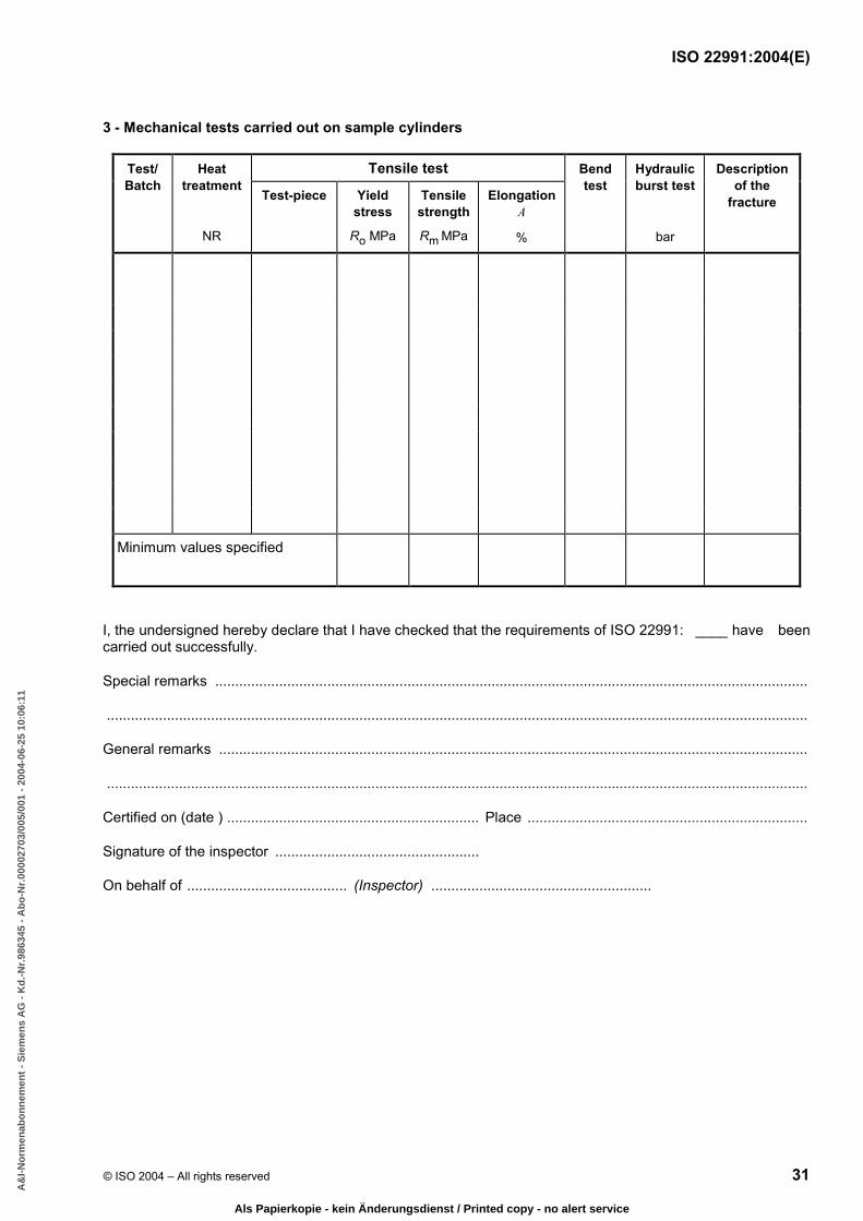
ISO 22991:2004(E)
© ISO 2004 – All rights reserved 31
3 - Mechanical tests carried out on sample cylinders
Tensile test Test/ Batch
Heat treatment
NR
Test-piece Yield stress
Ro MPa
Tensile strength
Rm MPa
Elongation A
%
Bend test
Hydraulic burst test
bar
Description of the
fracture
Minimum values specified
I, the undersigned hereby declare that I have checked that the requirements of ISO 22991: ____ have been carried out successfully.
Special remarks ....................................................................................................................................................
...............................................................................................................................................................................
General remarks ...................................................................................................................................................
...............................................................................................................................................................................
Certified on (date ) ............................................................... Place ......................................................................
Signature of the inspector ...................................................
On behalf of ........................................ (Inspector) .......................................................
BA178AF3EC677050DBAC9B8DA5349567ADC990EEFF93F3B562D565BBCCE551B04FB30348A9F905D2BEBE2EE710159EC8B560C0BF30F077189D3B68E26A9F3C8A6364EAF5157E4DFF4A2F011E10AD206AF0BD6437B2B1BD93F7746FD35D925920EF33
A&
I-N
orm
enab
on
nem
ent
- S
iem
ens
AG
- K
d.-
Nr.
9863
45 -
Ab
o-N
r.00
0027
03/0
05/0
01 -
200
4-06
-25
10:0
6:11
Als Papierkopie - kein Änderungsdienst / Printed copy - no alert service

This page is intentionally blank.
BA178AF3EC677050DBAC9B8DA5349567ADC990EEFF93F3B562D565BBCCE551B04FB30348A9F905D2BEBE2EE710159EC8B560C0BF30F077189D3B68E26A9F3C8A6364EAF5157E4DFF4A2F011E10AD206AF0BD6437B2B1BD93F7746FD35D925920EF33
A&
I-N
orm
enab
on
nem
ent
- S
iem
ens
AG
- K
d.-
Nr.
9863
45 -
Ab
o-N
r.00
0027
03/0
05/0
01 -
200
4-06
-25
10:0
6:11
Als Papierkopie - kein Änderungsdienst / Printed copy - no alert service

ISO 22991:2004(E)
ICS 23.020.30; 75.200 Price based on 31 pages
© ISO 2004 – All rights reserved
BA178AF3EC677050DBAC9B8DA5349567ADC990EEFF93F3B562D565BBCCE551B04FB30348A9F905D2BEBE2EE710159EC8B560C0BF30F077189D3B68E26A9F3C8A6364EAF5157E4DFF4A2F011E10AD206AF0BD6437B2B1BD93F7746FD35D925920EF33
A&
I-N
orm
enab
on
nem
ent
- S
iem
ens
AG
- K
d.-
Nr.
9863
45 -
Ab
o-N
r.00
0027
03/0
05/0
01 -
200
4-06
-25
10:0
6:11
Als Papierkopie - kein Änderungsdienst / Printed copy - no alert service