GAS COOLED, MOLTEN SALT HEAT EXCHANGER DESIGN …
52
Transcript of GAS COOLED, MOLTEN SALT HEAT EXCHANGER DESIGN …


This report was prepared as an accaunt of Government sponsored work. Neither the Unite
nor the Commission, nor any person acting on bshalf of the Commission:
A. Makes any warran+y or representation, expres completeness, or usefulness of the information contaipd In thLs- report, or that the use of any information, apparatus, method, or process disclosed in this report
privately owned rights; OT
6. Assumes any liabilities with respect to the use of, or for damages resulting f any information, apparatus, method, or process d
As used in the above, "person acting on behalf a
contractor of the Commission to the extent that s or distributes, or provides access to, any information pursuant to his employment or co
with the Commission.

" ,
0mJ-2605
Contract No, W-7405-eng-26
Reactor Projects Division
GAS COOLED, MOLTEN SALT HEAT EXCHANGER - DESIGN STUDY
R. E. MacPherson
Date Issued
Oak Ridge National Laboratory Oak Ridge, Tennessee
operated by Union Carbide Corporation
for the U. S. Atomic Energy Commission
3 4 4 5 b 0363239 7

J
4
- 2 -
CONTENTS
Page No, A b s t r & c t . ~ . o o o . . D . . . o . i , . . . . . o . o . v . . 4 Introduction . . e . . . . . . . . . ., ., , . . . 5 summary . . . . O . O O . . ~ . . O . O . O O O . . ~ . . o ~ 6 Design Considerations . . . . . . . e . . . e . . . . . . 8
1. Heat Exchanger Configuration , ,, . . . . . . . 8 2. Finned Tubing . . . . . . e . . , . . . . . . 12 3 . Tubing Size . . . . . . . e . . . . , e e . . . 14 4. General.. . . + . . e * . + . , . . * * . . a . .16
Discussion . . . . . . e . . . . . . . . . . . . e . . 16 1, Countercurrent, Cross Flow Heat Exchangers . e . e .16 2. Countercurrent Flow Heat Exchanger . . . . e . 24
Conclusions, . . . . . . . . . . . e . . . . . ..24 Method of Calculation . . . , . . . . ., . . 31 Nomenclature . e e . . . e . . . . . e . e . 38 Bibliography . . . . . . . . . . . . . . e 40
F 1

6
f
- 3 -
LIST OF FIGURES
Page No.
Fig. 1 - Annular Heat Exchanger Geometry . . . . . . . . . . . . 9
Fig. 2 . Design Study Heat Exchanger Geometry. . . . . . . . . . 10
Fig. 3 . Annular Heat Exchanger Design Parameters. . . . . . . . 11
Fig. 4 . Tubing Size Optimization. . . . . . . . . . . . . . . . 15
Fig. 5 - Design Parameters for a Four-Pass Heat Exchanger Using H e l i u m at 300 psig with an 8500F In le t Temperature . . . . . . . . . . . . . . . . . . . . . . 17
Fig. 6 - Design Parameters for a Three-Pass Heat Exchanger Using He l ium at 300 psig Gith an 850OF In le t Temperature . . . . . . . . . . . . . . . . . . . . . . 18
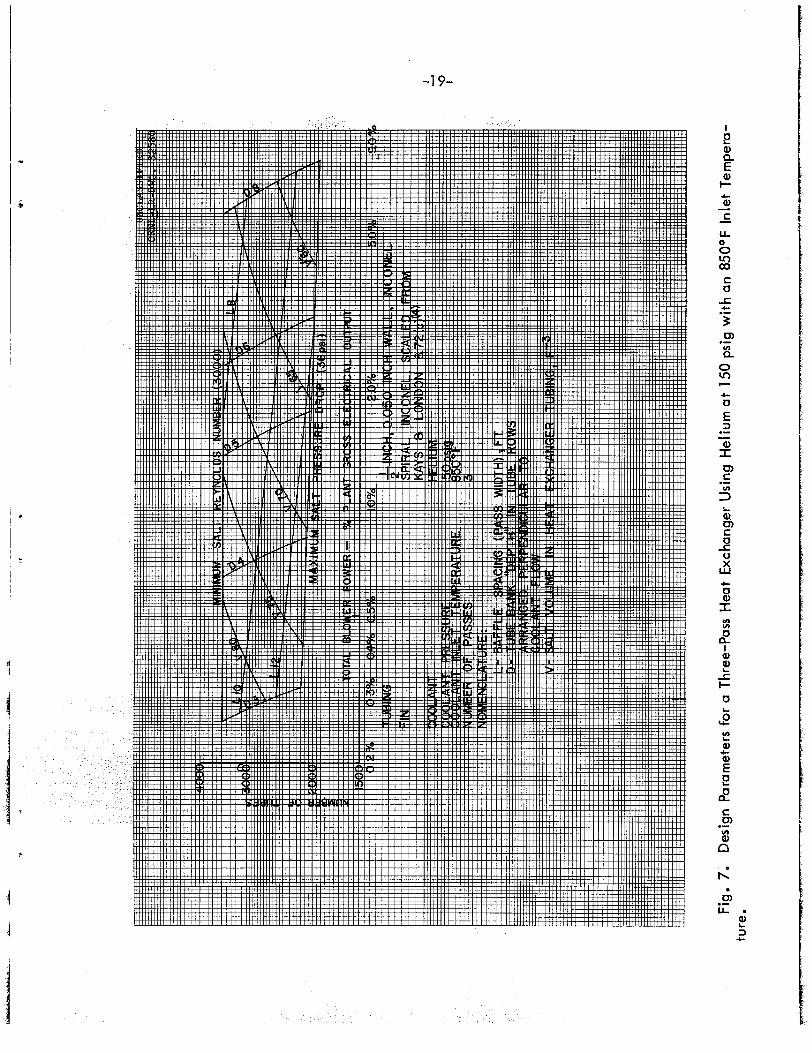
Fig,, 7 - Design Parameters for a Three-Pass Heat Exchanger Using Helium at 150 psig with an 8509 In le t Temperature . . . . . . . . . . . . . . . . . . . . . . 19
Fig. 8 - Design Parameters fo r a Four-Pass Heat Exchanger Using H e l i u m at 300 psig with a 700°F In le t Temperature . . . . . . . . . . . . . . . . . . . . . . 20
Fig. 9 - Design Parameters for a Four-Pass Heat Exchanger Using Hydrogen at 300 psig with an 8 5 0 0 ~ In le t Temperature . . . . . . . . . . . . . . . . . . . . . . 21
Using Steam at 300 psig with an 850OF Inlet Fig.10 - Design Par t e r s for a Four-Pass Heat Exchanger
c
Function of Total Blower Power Investment . . . . . . . 28 r
Cost per Heat Exchanger . . . . . . . . . . . . . . . . 29
Fige l? - Salt Volume i n Return Bends of Serpentine Fuel Tubes fo r a Four-Pass Heat Exchanger. . . . . . . . . . 37

- 4 -
ABSTRACT
One of the major problems i n the economic evaluation of the application of forced circvlation,<gas cooling t o high temperature, molten salt power reactor systems is the definition of the required heat transfer equipment, i t s s ize ana operating cost. changers f o r such a gas-cooled system has recently been completed, and the
results are.repoPted.
varying heat exchanger tubing size, coolant inlet temperature, coolant pres- sure level, allowable salt pressure.drop and uranium enrichment of the molten salt are demonstrated.
A design study of the.salt-to-gas heat ex-
Hel ium, hydrogen and steam are considered as coolants. The effects of
The relationship between heat exchanger dimensions, fuel inventory and blower power requirements i s presented i n graphical form for the most pertinent cases. exchanger overall s ize as a function,of coolant type and operating conditions,
Hydrogen isrshown t o be the most effective of the coolants considered, with steam and.helium being roughly comparable. t o be equal, helium can be made competitive with hydrogen by operating with
a 50 - 60$ higher helium temperature gradient through the heat exchanger. Opt imum heat exchanger geometries based on gas blower power costs and en- riched fue l inventory charges require a t o t a l blower power investment of approximately 0.5% of the plant gross e lec t r ica l output. reductions i n heat exchanger s i z e can be realized by going t o higher blower power investment levels.
Comparisons are made of annual operating costs and heat
Assuming other conditions
However, substantial

- 5 -
Introduction Since the early phases of design evaluation on a molten salt power reactor
system, it has been desired t o investigate the problems associatea with the use of gas as the primary coolant. A s a step i n t h i s direction, a design study has
been carried out t o define the salt-to-gas primary heat exchanger which would be required i n such a system. output of 640 megawatts (le generated i n blanket and removed through blanket cooling system) and a gross electr ical output of 275 megawatts. has been given t o the use of helium, hydrogen and steam as coolants. ference design was based on the following:
The study concerns a reactor having a thermal
Consideration The re-
4 primary heat exchangers 1/2" Inconel tubing (0.050" w a l l ) Circumferential Inconel f i n s Helium coolant - 623 lb/sec
Inlet 850'F Outlet 1025 OF
Pressure 300 psig Cross flow
Molten Salt (Fuel 130) 1768 lb/sec Inlet 1210 OF
Outlet 1075 OF Four pass serpentine flow
as t o the desirabili
Power Reactor.

- 6 -
s-rgr 'T
A design study lias been completed covering the application of gas as the prima-ry coolant i n a molten 'salt power reactgr system. hydrogen and steam was investigated along with the effect of gas pressure level, gas inlet Lempemture level and tubing size.
The use of helium,
The basic heat exchanger geometry studied was a cross, countercurrent flow arrangement with the molten salt (Mixture 130 - 62 mol % LiF, 37 mol $ B ~ F ~ , 1 mol 9 UF 1 making,fo-ur-se&ntine passes ac:osB the gas stream (see Fig, 2).
use6 i n a l l the f ina l heat exchanger calculations. Consideration was given i n the i n i t i a l phase of the study t o other tube sizes, and the standard s ize chosen i s fe l t t o approach the optimum,
4 One-half inch Inconel tubing with circumferential Inconel f i n s was
Eea-t exchanger optimization has been based on three c r i te r ia : first, fuel. inventory i n heat exchaager tubes, return bends and headers; second, gas blower power requirements; and th i rd , minimum heat exchanger container di-
mensions. a t 9 mi~s /kwh .
exchanger gas in l e t temperature with the out&et temperature fixed, the use of hydrogen results i n a smaller uni t with a bower fuel inventory and power requirenent than ei ther helium or,steam, hydrogen usage must be balanced against these obvious advantages, The optimum helium and steam heat exchanger are approximately the stme i n dollars invested i n fue l and pmer but differ geonetrbcally i n that the steam uni t i s larger i n dtamter and shorter i n length,
Fdel inventory was evaluated a t $1355/ft 3 /year and electr ical pover
Results of the study (Figs. 1 2 and 14) have shown that, at a given heat
Hovever, Yae hazards of large scale
Since a greater prexgmn i s attached t o diameter
i n the construction of the reqv..ired heat exchanger contsime!nt pressure vessel, the s t e m unit i s judged s l ight ly infer ior t o the I?e!-ium unt t dimensionally. Hovever, there &re imporkant incentives f o r the use of steam cooling. original cost of the steam inventory is negligib2e and the contaimmxt problem becomes o f minor importance, components can be used th%ou@out a steam system, clude6 tha t the application of steam t o t'ae gas cooling cycle would have eco-
The
In addi-t%on, stand&rd and. well de On th i s basi
nomic adwntages over helium.
and. heat load affects the coolant pumping power approxLmate2,y as the inverse Changing the coolant pressure bevel f o r a given heat exchanger configuration

- 7 -
square o the pressure ra t io ( i r e e , doubling pressure reduces pumping power t o one-fourth) Changing the coolant pressure level while maintaining a reasori- . ably constant blower power input affects primarily the required face area of' the heat exchanger with consequent changes i n container size.
Increasing the allowable salt side pressure drop increases the heat ex- changer container diameter while reducing i ts length. variable was not undertaken i n the present design study.
Decreasing salt enrichment by a factor of f ive results i n a reduction of yearly heat exchanger costs by factors of 2.5-4 i n the cases of primary interest e
The results of a companion study on longitudinal, countercurrent flow
Optimization of t h i s
of coolant over circumferentially finned straight tubing showed t h i s arrange- ment t o be somewhat l e s s a t t ract ive than the comparable crossflow case.
the heat exchanger container diameters were approximately the same, the re- quired container lengths were 30 - 4% greater. The use of such a straight tube geometry leads t o thermal s t ress problems associated with discrete tube plugging or flow variations from tube t o tube.
Although

- 8 -
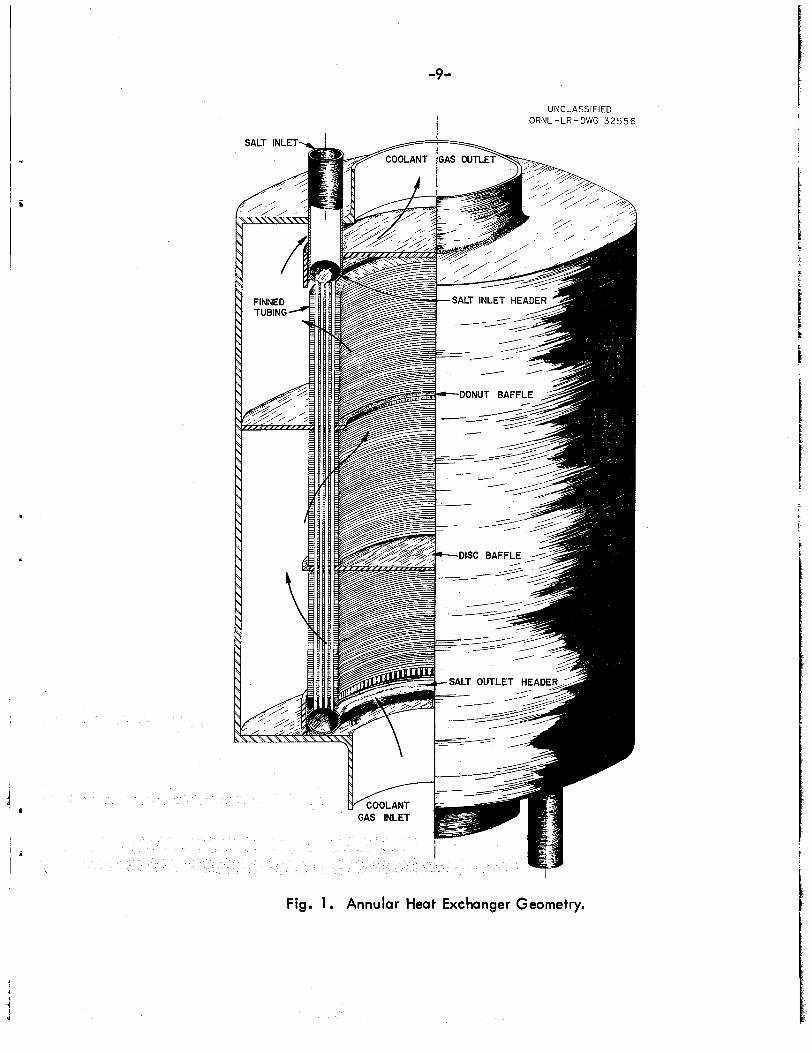
ger Conf igdration e ra l heat exchanger configurations i l lus t ra ted i n Figures 1
2 were given detailed consideration. cted as the l ea s t desirable of the two, was basically an annular
The first, which was ultimately
tubing arrangement with the salt flox sttraight through and the helium -countercurrent f lov around disc and donut baffles. The an-
ry imposed no restr ic t ion on the number of helium p s s e s e bundle since the helium could be in%roduc:e2 and col- a1 esse bo%k t o or from the ceater of the tube bmue he outside of the bmC!e, ace 1, a three-pass arrwgement was chosen as giving a
Base6 on correlations pre-
satisfactory approach t o pure countercurrent heat transfer ( i e e Q 9 es- sent ia l ly no correction factor t o be applied t o the log mean temperature difference based on the hot and cold stream inlet and outlet temperature under consideration). A t the same t ine, 8 s w i l l be shown later, keeping the numbe;P of passes t o a minimm restil-ts i n the most compct he8t ex- chcmger geometry.
Qne disadvantage of t h i s arrangement i s that, since straight tubes are used running fromthe salt i d e t t o the salt outlet header, plugging 05 one tube could lead t o a serious different ia l t h e m expasion condition, tubes could cause thermal stresses t o be imposed on the tubing and
f low fluctua-kions i n individual tubes could lead -to s t ra in cycling of tubing m t e r i a l , a simple geonetrical armgement such as a right m&e bend in %he tubing a% o r near ei ther the apper or l o~fe r header, it cannot be considered as a major stumbling block t o the use of t h i s geometry. appeered during the course of the study. from a fuel inventory an6 overall s ize stand,point proved. t o have internal
Mmeters which resulted i n high gas velocities as shorn in Fig, 3 . head losses associated with changes i n coolant flow direction and ve- loc i ty i n t h i s geometry are hard t o evaluate precisely, but it m s es- timated tha t 2 - 3 velocity heads would be l o s t per pass, Since t'mese losses approach i n magnitude the losses associated with f l o w across the
To a lesser extent, flow dispar i t ies between. sepamte
Since t h i s condition could be relieved somewhat by
The primary obstacle O p t i m heat exchanger geometries
The
-9-
UNCLASSIFIED I ORNL-LR-DWG 3 2 5 5 6
Fig. 1 . Annular Heat Exchanger Geometry.

-1 0-
UNCLASSIFIED ORNL-LR-DWG 31210
FINNED TUBE MATRIX
Fig. 2. Design Study Heat Exchanger Geometry.

-11-
Fig. 3. Annular Heat Exchanger Design Parameters.

- 12 -
heat transfer surfaces, they were f e l t t o be prohibitive, The annular * bundle was therefore rejected as a suitable geometry.
second heat exchanger geometry considered was a more n t having serpentine salt tubes with the gas flowing
entional ight
.,
through the heat transfer matrix, In t h i s case, it was
sary t o provide a four pass arsangement t o provide c
diff
ing
al t h e m expansion i n the tubing while avoi which would be required i f only three passes
, the four pass arrangement allows the salt inlet close together, an arrangement which stands t h
the amount of piping required t o connect &he he
All f ina l optimization studies were done on the basis of the serpen- t i ne salt tube arrangement.
A study was also made of the required heat exchanger geometry and
o-gemting costs f o r the case of countercurrent flow of helium over c i r - cunferentially finned tubing. so the results may not represent the best t ha t can be done with t h i s heat exchanger type, However, they are satisfactory as a rou remainder of the study.
The finned tubing geometry was not optiimized P
e-in with the
2 , Finned Tubing Several design restrictions imposed a t the .time the he
stu&j was undertaken made it desirable t o select a Timed tubing for con- sideratio@. that was less than the optimum from a heat t Inconel tubing was chosen since data on the thermal. eo a more l ike ly material of fabrication, are currently zmg?e&
f in s fabricated of Inconel were chosen t o avoid completely any
nbterials incompatability i n view of the extended l i f e power reactor heat exchanges, The use of nickel f i n s W Q U ~
t in a more compact heat exchanger, sement over nickel but would introduce the require
Copper core f i
f i n s t o the tubing i n order t o protect -&he cogper a of attack by the coolant or by impurities therein. the Introduction of the brazing requirement is cons

- 13. -
i
primarily from a materials compatability standpoint. information received f rom the GPiscom-Russell Corporation'') , a bond efficiency of loo$ was assigned to the mechanical bond between the Inconel fins and tubes.
On the basis of
The use of longitudinally finned tubing with the coolant in pure countercurrent flow WBS not investigated, since literature references (293)
indicate a continuous longitudinal fin to have poor heat transfer characteristics. The use of a split longitudinal fin OF pin fins mlght result in a competitive heat exchanger; however, these choices were not investigated since it was felt that simple mechanical bonding of such fins to the 'cubing could not be guaranteed to give the r of stpuktural reliability,
perimentally evaluated by Kays and. Londd4). The tubing dimensions The circumferentially finned tubing configuration chosen was ex-
listed below were scaled up from the eqerimental tube as indicated,
Tube O.D,, in. Tube I.D., in.
Experimental Tube Design Study Tube 0.420 0.500
0 .bo Fin O,D,, in, 0 861 1.024
Fin thickness, in. 0.019 0.023 Fin pitch
Tube pitch parallel to flow, in. perpendicular to flow, in.
8 72 fins/inch
0.800
0 975
7.32 f ins/inch
0 952 1,160
S
at the University
+.
Tube 0, D., in. Experimental Tube Design Study Tube
0 649 0 500
Tube I. De, in. -_ 0.400 Fin 0 , D o 9 in, 102% 1 .ooo Fin thickness, in. eo255 0.0197 Fin pitch. 5.85 fins/inch '7.60 f ins/inch

, TL
- 14 -
,ng Size The majority of the design study was based on 1/2 inch tubing with
a .C5C inch w a l l thickness. Figure 4 presents the pertinent information leading t o the choice of t h i s tubing size.
It can be demonstrated that the optimum salt inventory f o r a given set of design conditi’ona occurs when the unit i s sized so tha t %he salt
pressure drop through the heat exchanger i s at the maximum allowable value. has been customarily assigned t o the heat exchanges has been ut i l ized by entrance and e f i t effects.
This maximum i s 36 psi, since 10% of the available 40 psi which
Furthemore, based on the assumption t h a t the amount of power t o be ut i l ized i n coolant circulation would be between 0.5 and 10% of the plant gross e lectr ical output as extremes, the range of tube lengths and number of tubes which meet design re- quirements for a given tube size.
it is possible t o define
On t h i s basis, the l ines representing the length vs number of tubes a t maxilinun salt pressure dro-g f o r 3/4 inch, l/2 inch and 3/8 inch tubing wi-bh 0,050 inch w a l l were established. The location of the l ines re- presenting blower power investments of 0.5% and 1% of the plant gross e lectr ical output demonstrate tha t there is a f a i r l y narrow range of length-number of tubes combinations which will sa t i s fy the design re- quirements.
Three-fourths inch tubing was judged t o be undesirable because of time exeessive length requirement, although the number of tubm required, f o r the heat exchanger was very at t ract ive, was judged somewhat unsatisfactory f o r the opposi$e reason, Al-bhough
the tube length was satisfactory, the nmiber of tubes required was
Three-eighths inch tubing
judged excessive. One-half inch tubing seemed t o represent a reasonable approach t o optimum, although 7/16 inch tubing might be presumed e q W l y satisf actory.
It should be pointed out that increasing the wall thickness of the heat exchanger tubing from 0,050 t o 0.060 - 0,065 inch would have a negligible effect om the calculations, The t o t a l resistance wall t o heat transfer normally approximated 10% of the overall resistance.
a

i
b
h
0 0 0 0"
0 0 8
0 0 8
0 0 0 cu
0 0 0
0 8
W m - 2 t-
* 0
[r: w m 5 z
e C 0 .- 4 w .- E .- 4
0" Q) N .- v)
0 C .- h 3 I-
< * cn
LL .-

- 16 -
4, General The reactor core heat load of 574 thermal megawatts was arb i t ra r i ly
divided among four primary heat exchangers of 143.5 megawatts capacity each, Sal t and helium physical properties were evaluated a t the i r mean temperature i n the heat exchanger. was arb i t ra r i ly assigned as follows:
Coolant blower efficiency was taken as 80%~
The pressure drop distribution i n the coolant c i rcui t
Heat Exchanger 6% Steam Generator 3% Ducts 10%
Fin efficiencies were taken from correlations presented by Gardner ( 8 ) . 2
The salt pressure drop was taken as 40 psi total , with lO$ assigned t o entrance and exit effects and 9 6 assigned t o heat exchanger tube f r ic t ion losses, factor of 8% was assigned t o the power plant.
Coolant blower power cost was evaluated a t 9 mills/kwh, and a load
Enriched fuel was assigned a yearly cost of $1335/ft 3 based on the following factors:
Barren salt - $1278/ft 3
1) Capitalized a t 14%
per year $179 - u-235 - $17/gm
1) 2) Rental a t &$/annum
.48 Mol $ UF4 i n fuel
- $1156 $1335
Sn calculating coolant gas pressure drop across the tube bundle, the head loss due t o flow acceleration caused by temperature and pressure change was neglected, ture rise, the error resulting from t h i s assumption is w e l l within the limits of error of the overall calculation,
Due t o the low pressure drop and coolant tempera-
Discussion 1. Countercurrent, Cross Flow Heat Exchangers
Figures 5 t o 10 present heat exchanger design study results f o r a given coolant, coolant pressure level, coolant i n l e t temperature and
number of cross flow passes. Lines of constant baffle spacing, tube bank "depth" and salt volume i n the tubing are given i n each case on

-1 7-

-1 8-
-1 9-
I 0 L a, Q E
0 0 rr) 00 S 0
cn Q .- In
.- s
c 0 a, I v) In
0 P- I a,
-r I- L
E
E e n
a, a, 4-
0
S u)
a, .- v)
n

-20-
l
Q) Q
Q) I-
e E
c 0 Q) I
U a I
v) v)
L
0' L 0 L
2 2
E E a
Q)
Q) C
0
E

-21 -
an v) 0
C L I 3 0 L
L
e
E e
P)
P) c
0 C L

-22-
I e a Q
a I-
E
C a S - -
E B c m
L. 9)
D -c v X
W
P
c U a I v) v)
0 a I 3 0
LL
L
U L
22 v) L
C a a E e n U
S u) .- In
I5 e 0

c
t
- 23 - % *
a basic plot of blower power investment versus the number of tubes, The active length of eaeh he&% exchanger tube is the product of the baffle spacing times the number of passes. along a line of constart tube baak "depth" between the number of tubes at which the fuel Reynolds Number is 3000 (3500 tubes) and the number of tubes at which %he fuel pressure drop is 36 psi are satisfactory
A l l heat exchangers falling
f o r the transfer of 143.5 megawatts from the salt to the coolant under the conditions specified. However, those Paraits represented by the intersection 0% a line of constant tube bank "depth" with the line of I'na;ximura fie1 pressare drop represent the optirmun heat exchaagers from a. Pael inventory staarndpoint.
Since tube bank "depth" is given in number of tube rows, the value &st be an integer, normally in the range of two to fifteen. the figures w i l l make clear that for a given blower power investment them is one "best" heat exchanger geometry. As blower power is in-
Study of
a creased, the required number of tubes decreases until the optimum geometry for that tube bank "depth" is reached at the intersection wfth the mxim salt pressure drop line. horfzon%al projection of the line representing the next higher tube bank TPdepth"2 a much larger heat exchanger will also opemte at this same @QWW level, arad further power increases require heat exchaagers re- psesentecl by points along the higher "depth" line, viously referred to is not insiae the horizontal projection of the next higher tube bank. '*depth", there is a a g e of power vdues wbich cannot
If this point is inside the
If the point pre-
~ be used ho suitable heat Wger configuration e%eists in this mnge 0
%he vdues on the abscissa (Total Blower Power - $ of Plant Gross Fdeetrical Output) represent %he proporkion of 275 megawatts which is
four primary changer
four heat exc is w tion assignable to one heat
exchanger is 15$ of the abscissa value, Design study results are presented for the follossing cases:

- 24 -
C i rcui t Number of Coolant In le t Temp. OF Pressure,psi Passes Pig, Hoe Helium 850 300 4 5 Eelim 850 300 3 6 Eelim 850 150 3 7 H e l i u m 700 300 4 8 Eyarogen 850 300 4 9 S t e m 850 300 4 10
2, Comtercurrent flow heat exchanger re 11 presents the results of the study on pure longitudinal
urrent flow over ciscumferentially finned tubes. The case for heaim a t 300 psig with an i n l e t temperature of 8 5 0 " ~ is considered. In th i s figure, the length represents the t o t a l active length of tbe finned tubing and the pitch represents the tube spacing in , a "delta" armgement,
@Qll@lUSiOXlS
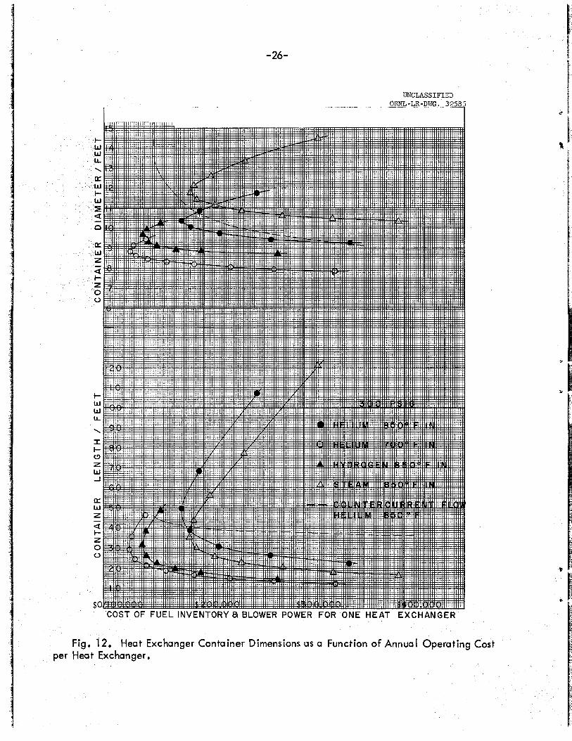
Figure 12 presents optimization curves f o r the various coolaats a d ogemting conditions i n the fsm of yearly cost o f fuel inventory
ben&h a~c? d.imeter. case presented, it must be realized tb-t the cost of heat axchanger fabrication and the effects of heat exchaager size on overall p l a t con- s%metioil costs have not been considexed i n this presentatfm, a53aa3 percentage increases i n yearly operating costs above the optimum v'due shmm i n Fig, 12, sizable PedUCtfQnS i n heat axchmger length are realized. Determination of how far o m should go i n t h i s d i m c t i m i i d be one necessaq step i n an overall plant ~ C O X X I L ~ ~ analysis.
mo~at a t t ract ive coolm%. If it is desired to avoid the hazards o f
hyamgen usage, reauction of the helium inlet tempmture tc 700°F (mintaining the outlet tempemtme of 1025°F constant) gives a tmit smaller and cheaper t o ogemte than is the case f o r hyarogen at the higher in l e t temperature level. "&fch is lower than the freezing point of the Nifiure l3Q (850"~ com-
blower p w e r for one heat exchanger versus heat sxchmger ~ ~ ~ ~ k i a ~ e r n p
Although an eCOnOmi@ Q l p t i m m is found for each
By
Far a given set sf operating conditions, hydrogen -groves t o be the
~%5s~a
Use o f a coolant inlet temperature

! -
I P
-25-
-26-
UNCLASSIFIED ORNL-LR-DWG. 32585
1 . .._ _ _ s I ..
Fig. 12. Heat Exchanger Container Dimensions us a Function of Annual Operating Cost per Heat Exchanger.
I - 27 -
I - 9
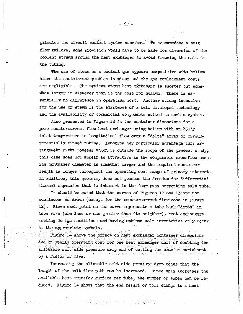
plicate8 the circui t coiltrol system somewtmt, bo accommodate a salt
flow failure, some provision would have t o be ma.& for diversion of the coolant stream around the heat exchanger t o avoid freezing the salt i n the tubing.
The use of steam ab? a coolant gas appears competitive with helium I
since the containment problem is minor and the gas replacement costs &re negligible, what larger i n diameter than is the caae f o r helium.
The ogtimm steam heat exchanger is shorter but some- There i s es-
s e n t i d l y n~ difference i n operating cost, Another strong incentive for t he use of steam is the existence of a well developed technology and the avai labi l i ty of commercial components suited to such a system.
Also presented i n Figure 12 is the container dimensions fo r a
pure countercurrent flow heat exchanger using helium with an 8 5 0 ~ fadlet, temperature in l o n g i t u d i w flow over a. "delta" array of" circum- f e r e n t i d l y finned tubing. Ignoring any particular admatage t h i s ar- rangerneht m i g h t possess which i s outside the scope of the present study,, this case does not appear as at t ract ive as the comparable crossflow case. The eontaine~ diameter is somewhat larger and the required container length is longer thrsu&out the opemting cost m g e of' primary interest,. I n addition, th i s geometry does not possess the freedom f o r differential. t h e m expasion tha t is inherent i n the four pass serpnt ine salt tube!.
It should be noted that the curves of Figares 12 and13 are not
1 continuous as drawn (except for the c
12). tube rows (one less o r one greater t
Since each point on the cum@ represents a tube bank. "depth" i n its neighbor) heat exchangers im salt inventsees only occur
. I
Increasing the allowable salt side pressure drop mwns tha t the
length sf the salt flow path @an be increased. Since % U s increases the I available heat transfer surface per tube, the number of tubes can be re-
duced. Figure 14 shows that the end result 02 %his change is a heat

-28-
0,
c 03
3 0
J
4
Y E I-
J w 9 v) v) 0
(3 a
a 5 2 K
2 g d

-29-
~
~
Fig. 14. Effect of Varying Allowable Salt Pressure Drop and Uranium Enrichment on Annual Operating Cost per Heat Exchanger.

- 30 -
exchanger container larger i n diameter and shorter i n length than is the case with a smaller salt side pressure drop, There is a pmctical l i m i t t o how far the design should be carried i n th i s direction. diametef of the contaiment vessel becomes too large f o r the eorrespnd- ing length, a change t o a s i x salt pass geometry should be investigated, The present study was not carried t h i s far, but the basic equations l i s t ed i n Table 6 are applicable fo r t h i s purpose,
When the
igure 14 also i l lus t ra tes the effect of lowering u r a i m enrich.- a factor of five. In the area of interest , th i s reduces annual
ng charges f o r blower power and fuel inventory t o 25 - b$ of at the higher enrichtnent .
results of t h i s study can be used t o predict the heat exchanger requim&ents for increased or decreased reactor power levels for the specific cases and opemting conditions considered, Tbe length of the
heat exchanger i s a direct function of heat load and a direct ra t io can therefore be applied t o t h i s dimension, provided the change is not so great 8s t o disproportionate the length-diameter relationship of the heat, exchanger containero

- 31 -
Method of Calculation Case - 640 thermal megawatts -
576 megawatts ;in reactor core 64 megawatts in blanket
275 electrical megawatts 4 primary: core circuit heat exchangers Helium coolant 300 psig,coolant pressure 8 5 0 ' ~ I coolant iflet, temperature
1/2 inch Inconel, 0.050 inch wall thickness "delta" array, modified 1.19 inch tube sgacing perpendicular to flow
4 serpentine salt passes Tubing -
0.952 inch r o w spacing pamllelto flow
1.024 inch outside diameter - Fins - Inconel, mechanically bonded, circumferentially wound
0,023 inch thick 7.32 f ins/inch
Operating Conditions Salt Inlet Temp. '' Outlet Temp. H m 'I Mean Temp. '' Flow
Temp.
Physical Properties Salt at 1143'F
heat capacity
1210 O F
1075 "F 135 O F
1143°F 1768 lb/sec 850°F
io25 OF
175 "F
937°F 300 PSQ3 4,89 x 10 8 lBTU/hr
203.5"F
0.57 BTU/lb"F
t

viscosity thermal conductivity density Prandtl Number
Helium at 937°F heat capacity viscosity thermal conductivity density specific volume Pmdtl Number
Inconel at 1000QF thermal conductivity
Salt Pressure Drop
f = .31& S
(Re)se25
- 32 -
22.76 lb/ft hr 3.5 BTU/hr ft"F
122.7 lb/ft3
3 706
1.248 BTU/lb°F 0.0865 lb/ft hr 0.175 lBTU/hr ftQF 0.084 lb/ft3 ll.9 ft3/lb 0.616
140.4 W/hr ft°F
= 10.41 x 10 6 N
S 4w s = D O W (Re)s = e
S Ai Ps 7LDeNP
OP = 0,0578 (L) = 36 psi s (N)1*75 (De )4*75
De = 0.0333 ft
(L) = .Bo1 x 10 -4 (N)l*75 Helium Pressure Drop
h

- 33 -
I
2
2
2
A - 0.768 f t f i n area/ft tube - 0.109 f t tube area/ft tube 0,877 f t t o t a l area/ft tube
2 A = 0.877 L . N f t
A = 0,0476 L . M f t 2 C
1 = .952 D f t . 12
2.8
- - 1 = 1 + t f i A , +$A, C kI% s s A U h

- 34 -
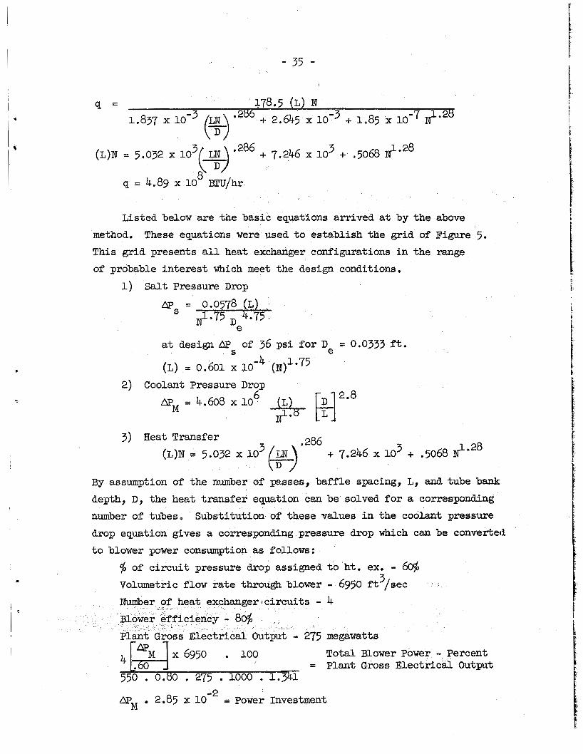
- 35 -
q = 178.5 (L) N 1,837 x loe3 (y ) *2'6 + 2.645 x 10'' + 1.85 x 10 -7 N 1.28 -
(L)N = 5.032 x 10 *286 + 7.246 x lo3 + ,5068 d*28 q = 4,89 x 10' BTU/hr
Listed below are the basic equations arrived at by the above method. This grid presents all heat exchanger configurations in the range of probable interest which meet the design conditions.
These equations were used to establish the grid of Figure 5.
1) Salt Pressure Drop
at design AP of 36 psi for De = 0.0333 ft. S
(L) = 0.601 x i o -4 (N>l*75
2) Coolant Pressure Drop = 4.608 x 10'- (I,!~ E]"" @M
3) Heat Transfer (L)N = 5.032 x 10 3 ($286 + 7.246 x lo3 + ,5068
By assumption of the number of passes, baffle spacing, L, and tube bank depth, D, the heat transfer equation can be solved for a corresponding number of tubes, Substitution of these values in the coolant pressure drop equation gives a corresponding pressure drop which can be converted to blower power consumption as follows:
$ of circuit pressure drop assigned to ht. ex. - 60$ Volumetric flow rate through blower - 6950 ft3/sec Number of heat exchanger <circuits - 4
, trical Output - 277 megawatts Total Blower Power - Percent :+s8; :::5 e e l o ~ ~ , 1.341 = Plant Gross Electrical Output
APM 2,85 x 10
~
-2 = Power Investment
!

- 36 -
The salt pressure drop equation was used t o define the number of tubes at which salt pressure drop is a maximum f o r a given baffle spacing, Lo and number of passes. The salt Reynolds Number equation
(Re)s = 10.41 x 10 6 N
defines the m a x i m number of tubes which can be used without going below a given Reynolds number, In all cases, 3000 was taken as the
I h i n i eynolds number, FOP the 1/2" tubing under consideration t h i s s the m a x i m number usable.
f o r the various cases presented i n Figures12,
13 and 14 were based on the parameter values taken from their respective grids at the intersection of the l ines of constant tube bank "depth" with
the l i ne of maximum s a l t pressure-drop.
D, L, M and N fo r each case as w e l l as the fuel volume i n the tubes. fuel volume was obtained from Figure 15 and header volume was calculated on the basis of a cone with a base diameter of 16.5 inches and a length determined by 0.1 M feet .
Th i s defines power investment, Bend
-

- 37-
Fig. 15. Salt Volume in Return Bends of Serpentine Fuel Tubes for a Four-Pass Heat Exchanger.

A -
Ac - "i
A T - % -
-
- 38 -
Nomenclature e f i n plus tube heat transfer area/pass, ft 2
2 coolant f ree flow area, f t
salt flow area, f t 2
D -
f - e
f - S - %
Gc - h -
l i -
5 -
C
S
N -
r - h
t o t a l heat transfer area (A . R), f t 2
hean tube wall area, f t 2 salt side heat transfer area, f t 2
coolant specific heat, E?TU/lb°F tube bank "depth", i n tube rows arranged perpendicular t o direction of flow salt side equivalent diameter, f t
coolant Fanning (small) f r ic t ion factor salt f r ic t ion factor gravitational constant, f t /sec 2
coolant mass velocity, lb/sec f t 2
salt heat transfer coefficient, BTU/hr f t 2 OF coolant heat transfer coefficient, BTU/hr ft2"F
Colburn j-factor h (Pr)
Inconel thermal conductivity, BTUihr f t ')?/in salt thermal conductivity, BTU/hr ft2"F/ft tube bank depth/pass, f t
baffle spacing (pass width), f t
t o t a l tube length (L.R), f t
2 [q "4
number of tubes i n a row perpendicular t o coolant flow (M = M/D) t o t a l number of tubes
t o t a l coolant pressure drop (me . R) , lb / f t2
koolant Pmndtl Number
t o t a l heat load, BTU/hr
tube bank hydraulic radius, f t
4 r h = 4 A 1 A
coolant pressure drop/pass, lb/f t 2
salt pressure drops lb/ in 2
(7) C --

- 39 -
i
R - number of crossflow passes (Re) c- coolant Reynolds Number (Re)s- salt R e y n o l d s Number t -
&LM- u -
tube w a l l thickness, inches log mean temperature difference, O F overall heat transfer coefficient, IJTU/hr ft 2 O F
coolant specific volume, ft’3/~, salt velocity, ft/sec fin height, inches coolant flow rate, lb/sec salt flow rate, lb/sec fin thickness/2, inches
coolant viscosity, lb/ft sec salt viscosity, lb/ft sec
fin efficiency (8)
salt density, lb/ft 3

- 40 -
Bibliography 1.
2,
3.
4,
5.
6. 7. 8.
9.
Personal communication of writer with representatives of Griscom- Russell Corporation during a visit to the Oak Ridge NationaJ Labopatopy. McAdams, W. H., Heat Transmission, 3rd Edition, p. 269 Norris, R. H. and Spofford, W. A., ASME, Advance Paper, New York (December, 1941). Kays, W. M. and London, A. L., Compact Heat Exchangers, The ;National Press, 1955, p. 114. Knudsen, J. G. and Katz, D. L., Heat Transfer and Pressure Drop in Anmuli, Chem. Eng. Prog. 46, 490 - 500 (1950). Op.Cit., Compact Heat Exchangers, p. 21.
Ibid, p. 3. Gardner, K. A., Efficiency of Extended Surfaces, Trans. ASME, 67,
Amos, J. C., MacPherson, R. E., Senn, R. L., Preliminary Report of Fused Salt Mixture 130 Heat Transfer Coefficient Test, ORNL,
CF Memo 58-4-23, April 2, 1958.
-
621. - 631- (1945).

- 41 -
I
8 . v\
M m mcu . . 0 0 0
0 0 0 0, O, 0, cu 0"s s r f c u M
V W
P. . a
0 - 0 i - i
0 0 0
q
Ln M O O
u3 *cucu I+
a n m 4
* G ,
n Ln *

- 42 -
n
t- ? 0 0
0 0
n M O, 0, k g
8 0
w ch . Ln
0
f ? 0 0
0 0
con t - c n 0, O,
0 0 0
95 con
rl
rl s. M
0 0 0 0
rlu c o d rl
O, O,
0 0
t- cu cu
O,
?,-! c o n
rl
rl
cu L? 0 0
0 0
* t - coo o , ?
0 0 o,
n f v n u W
%? cow
rl
cu co c';
n 5
rl rl 0 0
M w O.\
0 0
ln t- O,
sc9 coco rl
rl
co rl I
0 ? w Ln
co t-q 8 2
8 0,
'?-?
63 c1 0
cu a,
??"e O 0 *n*n 0, 3 c u t -
ch ch
0 0
K\ M O,
w 8 0, ch rl
0 0 0
?? con cu
-? 0
rl a' cu d n
cu. f
0
0 0
0 rl
O,
0 0
cn 01 rl
O, rl -P
r;: %
7 0
0 0
Ln O.\
0 s k 5 0 k
3 c o 0 0 Fa3 -
.\ cu rf 4 e- rl e-
4 8 * k 0
Frl n n rl l- 4 k v
* * .+J rn 0 c)
1
-$ 0 V
r-i cd
8 h
4
4 -P 0 H

- 43 - rn M f . 0
0
f t- cu
0,
0 0
l- o\ rl
o,
0 0 0, rl
8 O-.
2 rl
0 0 0
f rl 4
8 o, cn M rl
0 0 0 M f rl
-.
0 0 0 9
L i rl
rl t
t rl
cu i rl
n f v h
W u
. ti
rl
M a, rl
H s ri
c
r-l
rl
r i
* k
* 2

- 44 -
at- d t - d c u
& & r i d
ri
d
* k
* 9
8 0, R
0, 8
Ln
0 0
M
0 0
2 t- cu
8 0,
8 O,
a M cu
4 0 0 O, &
8 O,
ri
v) a3 rl
0 0 0, % rl
?3 , t- 8
0, 0 0
d ;f cu
0 0
3 0, G
s
P

- 45 -
n Ln rl
Ln M c-
Ln co M
Ln
I cu
m cu rl
Ln
Fd
0 M Ln .
3 3
0 0
v) M cc 0 0
3 0 A-
0 0
cu \o cu
O,
0,
0,
8 0, E- m rl
0 0
2 rl
0 0
Ln Ln rl
0,
E: 0, 8
0, 3
rl
0 0
m
LncoM ,o 0 * * * 0 0
P- L n c u o m
0 t-9 0, 0,
? ? $ ? t-cucu M M f 01
ho
n M
n w M k - 0
I u

\o i/ H % ?
0
P
a3 cu ZiiZ
FI
O ' n ri
\o
x P 4 M Ln cu .
a3 cu
I 'I RIA,
x x x x x
0 R 8 0 0 Ln 0 8 rl M M

a3 cu rl
R \o 0 2 + 0 ri x
M
Ln cu. t-
a3 (u
ri 2 * cu 9 + 0 rl x
M
G f +
\o
- 47
a3 cu ri 2 t- 0 ? +
M a x
\o+
N.
x
t-
a3
I
a3 cu. % 3 +
M a x
% Ln
\o+
co (\I
% a3
+ 0 r i
x ln 01 c-
M
\o+
N. co
%= (r: a s x
cu
(u Q= I 0 rl x
cu
a= (r:
3
0 d x
Ln
0 0 Y R a M 0
El l8 .d ri
x x x * 2 ?
\o M d cu rl
0 0 0 R a M
i


-49- OR1TG- 260 5 Reactors - Power
TID-4500 (14th ed,
1. J. C. Amos 2. M. BendeY 3. D. S. Billington 4. F, F. Blankenship 5. E. P, Blizard 6. A. L. Boch 7. C. J. Borkowski 8. W. F. Boudreau 9. G. E. Boyd
10. E. J. Breeding 11. R. B. Briggs 12. C. E . Center (K-25) 13. R e A, Chaapie 14. J. A. Conlin
16. W e B. Cottrell 17. F. L. Cyller 18. L. B. Emle t (K-25) 19. D. E. Ferguson 20. 5. Foster 21. A. P. Fraas 22. J. He Frye, Jr. 23. W . T. Furgerson 24. B. L. Greenstreet 25. W. R . Grimes 26. A, G. Grindell 27. E. Guth 28. C. S. Harrill 29. H. W . Hoff’man 30. A. Hollaender 31. A. S. Householder 32. W. H. Jordan 33. G. W. Keilholtz 34. M e T. Kelley 35* B. W. Kinyon 36. M. E , Lackey 37* J. A. Lane
15 . J. H. C O O ~ S
INTERNAL DISTRIBWION
39. L. A, Mann 40. H, G. MacPherson 41. R. E. MacPherson 42. W . D. Manly 43. W. B, McDonald 44. J. R. McNally 45. K, Z, Morgan 46. J, P. Murray (Y-12) 47. M. L. Nelson 48. L. G. Overholser 49. A. M. Perry 50. C. A. Preskit t 51. H. W. Savage 52. A. W. Savolainen 53. H. E . Seagren 54. R , L. Senn 55. E , D. Shipley 56. 0. Sisman 57. M. J. Skinner 58. A, H. Snell 59. E. Storto 60. J. A. Swartout 61. E. H. Taylor 62. D. B, Trauger 63. 3’. C . VonderLage 64. C. S. Walker 65. A. M. Weinberg 66. G. D. Whi tman 67. C. E. Winters 68. M. M. Yarosh
69-70. ORNL - Y-12 Technical Library, Document Reference Section
71-90. Laboratory Records Depa#rtment 91. Laboratory Records,’ 0RNL’R.C.
92-93; Central Research Library 94. Reactor Exgerimental
Engineering Library
EXTERNAL DISTRIBUTION
38. R. S. Livingston
OR0 96-677. Given distribution as shown in‘TLD-4500 (14th ea.) ukder Reactors - Power
category (75 copies - OTS)