Garaventa EVACU-TRAC CD7
20
Garaventa EVACU-TRAC CD7 Emergency Evacuation Chair Owner’s Manual Item No. 12440 Rev E Printed in Canada
Transcript of Garaventa EVACU-TRAC CD7

Garaventa EVACU-TRAC CD7
Emergency Evacuation Chair
Owner’s Manual
E
Item No. 12440 Rev Printed in Canada
Evacu-Trac CD7
OWNER’S MANUAL
Table of Contents
1. Safety First Page 3
2. Terminology Page 4
3. Operating Instructions Page 5 Introduction Set-up and Loading Operating on Stairs
4. Storage Surface-Mounted Storage Cabinet Page 9
5. Service Page 10 Tracks Track Alignment Track Tension Factory Setting Track Tension Adjustment (Speed Adjustment) Track Removal and Replacement Track Cleaning
Brake Cable Adjustment Lubrication Spare Parts
6. Specifications Page 18
7. Warrant y Page 19
1

Garaventa Evacu-Trac CD7
Congratulations on the purchase of your new Garaventa Evacu-Trac CD7.
Evacu-Trac has been designed to provide an easy method of evacuating people with disabilities from multi-floor buildings.
Before using the unit, please view the Operator Training DVD and take a moment to read this manual carefully so you will have a thorough understanding of the operation of Evacu-Trac. Ensure that only someone who has been properly trained operates Evacu-Trac.
Although Evacu-Trac will be used infrequently, operators must be very familiar with the operating procedures. For this reason we recommend that personnel who are required to operate Evacu-Trac hold regular practice drills on stairways that would be used during an emergency. Operating procedures are fairly simple, and the confidence of a competent attendant will help to relax the Evacu-Trac passenger.
If you have any questions contact Garaventa by phoning 800-663-6556, or 1-604-594-0422 or by writing:
In Canada: Garaventa Lift In USA: Garaventa Lift 7505 – 134A St. PO Box 1769 Surrey, BC Blaine, WA V3W 7B3 98231-1769
Email: [email protected]
If you purchased from an Authorized Garaventa Dealer, record contact info:
Name: ____________________________________________ Address: ____________________________________________
____________________________________________ Telephone: ____________________________________________
Record your Evacu-Trac serial number in the space below, and refer to it whenever you call your Garaventa dealer about Evacu-Trac.
Evacu-Trac CD7 Serial Number: ________________________________
2

1 Safety First!
The safety warning symbol shown to the left is used throughout this manual to draw your attention to instructions that must be carefully followed to avoid possible dangers.
The following procedures are important to ensure the safe operation of Evacu-Trac:
CHECK THE STAIRWAY Do not use Evacu-Trac on curved or spiral stairs, irregular or insecure stairs, or stairs with loose carpeting. Use extra caution on wet or slippery stairs.
DO NOT OVERLOAD Do not use Evacu-Trac with a passenger heavier than 136 kg (300 lbs).
ENSURE SEAT LATCH IS LOCKED Do not place a passenger in the Evacu-Trac unless the seat frame is fully opened and locked. Check the indicator window. If it is blue, the seat is properly locked.
SECURE THE PASSENGER Do not use Evacu-Trac without securely restraining the passenger using the safety straps provided.
WEAR APPROPRIATE FOOTWEAR Do not wear high-heeled or slippery shoes when operating Evacu-Trac.
3

2 Terminology
Brake Release BarNote On Leg Safety Strap:
On more recent units the Leg Safety Strap has been repositioned to allow it to be used across the passenger’s upper or lower legs, depending on leg length. This position also allows the legs to be held together in a more secure position.
4

3 Operating Instructions
INTRODUCTION
To ensure the safety of the passenger and operator, read these operating instructions carefully and view the Operator Training DVD. Practice sessions should be held on a regular basis (monthly is recommended) to maintain operator proficiency. In addition, building occupants for whom the Evacu-Trac is provided should be familiar with and comfortable in using Evacu-Trac.
Descent speeds for lighter or heavier passengers will vary. If your passenger is heavy and you feel the descent speed is too fast, the operator should partially release the brake by lightly squeezing the Brake Release Bar until a comfortable descent speed is attained. Speed can also be reduced by increasing the track tension. See Page 11.
SET-UP AND LOADING 1. Place the unit on a flat
surface. Grasp the end of the Handle. Pull it out and up in a quick, smooth motion. On completion of this motion the seat will latch into its locked, open position.
2. Ensure Evacu-Trac is
properly locked in the open position. Check the Indicator Window on the side of the aluminum track frame. If it is blue the seat is properly
locked.
3. Transfer the passenger into Evacu-Trac.
5

4. Fasten the Safety Straps. If you cannot be certain that the passenger’s arms will remain in his or her lap, the arms should be wrapped inside the torso safety straps.
OPERATING ON STAIRS
Caution:
When operating Evacu-Trac on stairs always wear footwear with flat soles.
1. To roll on a flat surface push down on the handle.
2. Then squeeze the Brake Release Bar with both hands.
This will deploy the Front Auxiliary Wheels, making Evacu-Trac easier to push.
Do not try to lower the Front Auxiliary Wheels by pulling the Brake Release Bar without first pushing down on the Handle. This
may stretch the Brake Cable.
6

3. To turn on a flat surface,
press down on the Handle and pivot Evacu-Trac on the Rear Auxiliary Wheels.
4. Position Evacu-Trac at the
top of the stairs, at a right angle (90º) to the stairway, with the passenger facing towards the stairs. Operating Evacu-Trac near the inner core of a stairway will facilitate turning corners at landings.
5. Push Evacu-Trac forward
until the Front Auxiliary Wheels drop off the top step. At this point Evacu-Trac will stop. To prevent Evacu-Trac from immediately beginning to descend the stairs, release your grip on the Brake Release Bar. This will engage the Track Parking Brake until you are ready to descend. Lift the handle and tilt Evacu-Trac to the angle of the stairs.
6. To descend the stairs,
squeeze the Brake Release Bar. To slow the descent speed, if desired, simply loosen your grip on the Release Bar. This will partially engage the Brake.
7. To stop Evacu-Trac on the
stairs, slowly release the Brake Release Bar.
7

8. At landings, push down on the Handle and turn Evacu-Trac with all the weight on the Rear Auxiliary Wheels. Keep to the inside of the corner for maximum turning clearance. Align the machine at a right angle to the stairs and proceed down the next flight.
9. Find a flat surface to park Evacu-Trac. Let go of the Brake Release Bar. This will lower the front section of the Tracks to the floor, preventing the unit from rolling. Remove the passenger.
10. Unlock the Seat Latch by pushing down on the red Seat Latch Release Bar. Push down and forward on the Handle to fold Evacu-Trac closed.
8

4 Storage Evacu-Trac should be stored in an area that is readily accessible during an emergency and where there is sufficient room for making a transfer from a wheelchair. Recommended areas are in large upper stair landings or in the building interior as near as possible to the stairway that will be used.
SURFACE-MOUNTED STORAGE CABINETS
To install, find a suitable location and ensure that the cabinet rests on the floor with the back firmly against a wall.
To attach to a stud wall, locate the stud and drill two 8 mm (5/16in) diameter holes in the back of the cabinet. Fasten the cabinet to the wall using two 7 mm (1/4 in) lag bolts.
To attach to concrete or to a concrete block wall, drill three 8 mm (5/16 in) diameter holes as shown in the back of the cabinet. Position the cabinet against the wall and, using the drilled holes as a guide, drill three holes in the wall. The size of the holes will depend on the type of insert or plug being used. Insert suitable plugs and fasten the cabinet to the wall using lag bolts.
9
5 Service
TRACKS
Track Alignment
It is important that the Tracks are aligned with each other to ensure that the Track Lugs on both Tracks contact a stair nose at the same time.
Incorrectly aligned Tracks can cause Evacu-Trac to descend a stairway at an angle, reducing stability.
To check alignment, line up a specific point on one Track (e.g. the tip of a lug) with a specific point on the Evacu-Trac frame. Ensure that the same point on the opposite Track is aligned with the same reference point on the opposite side of the frame.
To adjust alignment, reposition one of the Tracks on the cog until the tracks are correctly aligned. To do this you will need to loosen the Tracks. See Track Tension Adjustment on Page 11. Note that you may have to try re-positioning the Track a few times to find a location that provides correct alignment.
After adjusting Track alignment, be sure to adjust Track tension to achieve the correct descent speed. See Track Tension Adjustment on Page 11.
Track Tension Factory Setting
Evacu-Trac is shipped from the factory with the Track tension adjusted to accommodate passengers weighing 90 to 120 kg (200 to 265 lbs). This was done using a special machine to electronically measure the total speed control force of the Governor and Tracks.
10
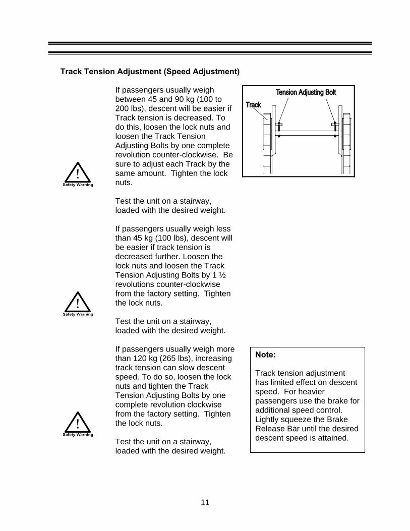
Track Tension Adjustment (Speed Adjustment)
If passengers usually weigh between 45 and 90 kg (100 to 200 lbs), descent will be easier if Track tension is decreased. To do this, loosen the lock nuts and loosen the Track Tension Adjusting Bolts by one complete revolution counter-clockwise. Be sure to adjust each Track by the same amount. Tighten the lock nuts.
Test the unit on a stairway, loaded with the desired weight.
If passengers usually weigh less than 45 kg (100 lbs), descent will be easier if track tension is decreased further. Loosen the lock nuts and loosen the Track Tension Adjusting Bolts by 1 ½ revolutions counter-clockwise from the factory setting. Tighten the lock nuts.
Test the unit on a stairway, loaded with the desired weight.
If passengers usually weigh more than 120 kg (265 lbs), increasing track tension can slow descent speed. To do so, loosen the lock nuts and tighten the Track Tension Adjusting Bolts by one complete revolution clockwise from the factory setting. Tighten the lock nuts.
Test the unit on a stairway, loaded with the desired weight.
11
Note:
Track tension adjustment has limited effect on descent speed. For heavier passengers use the brake foradditional speed control. Lightly squeeze the Brake Release Bar until the desired descent speed is attained.

Track Removal and Replacement
Since Evacu-Trac will be used in emergency situations only, wear on the Tracks should be minimal and Track life will be determined by natural environmental conditions.
The Tracks contain hundreds of steel wires, which eliminate stretching, and are covered by a thick coat of rubber. They are very durable, but should be replaced if they are cut or cracked in any way, or show signs of deterioration.
When re-installing the Tracks, check Track alignment as outlined at the beginning of this chapter.
Track Cleaning
To ensure maximum adhesion to stair surfaces, Tracks must be kept free of oil and dirt. Clean with a mild detergent and dry before using.
12
BRAKE CABLE ADJUSTMENT
Brake cable adjustment is set and tested at the factory. Under normal conditions it should not require further adjustment in the field.
The Track Parking Brake is a fail-safe design that is always engaged by the force of the Brake Spring in tension. The Track Parking Brake is released when the Brake Release Bar is squeezed. This action tightens the Brake Cable and releases the Brake.
If the Brake Cable is adjusted, it is critical that sufficient slack remains in the cable so that full Brake Spring tension is applied when the Brake Release Bar is in its neutral, parking position. Always test the Brake on the stairway, with rated load, after adjusting the Brake Cable.
Cable Adjustment Sequence
The Brake Cable is used to release the Track Parking Brake and to deploy the Front Auxiliary Wheels. For this reason it is important to use the following sequence when making Brake Cable adjustments:
13

1. Loosen the Rear Brake Cable Sleeve lock nuts and adjust their location on the Positioning Screw to provide approximately 13 mm (1/2 in) of free movement in the Brake Release Bar. This is the amount of motion that should occur when squeezing the Brake Release Bar before any movement of the Brake Cable occurs. If more adjustment is required you can also use the Cable Sleeve Positioning Screw at the other end of the Cable Sleeve, near the Brake Release Bar. Tighten the lock nuts after adjustment.
2. When you squeeze the Brake Release Bar it should travel until it just makes contact with the lime green Handle. This will allow you to comfortably hold Brake Release Bar in its released position when pushing Evacu-Trac on flat surfaces or descending a stairway.
The Brake Release Bar travel range is adjusted using the Adjusting Screws that control the Front Auxiliary Wheel Retracting Arm. Loosen the lock nuts and adjust as required. Test the action of the Brake Release Bar and then tighten the lock nuts.
14
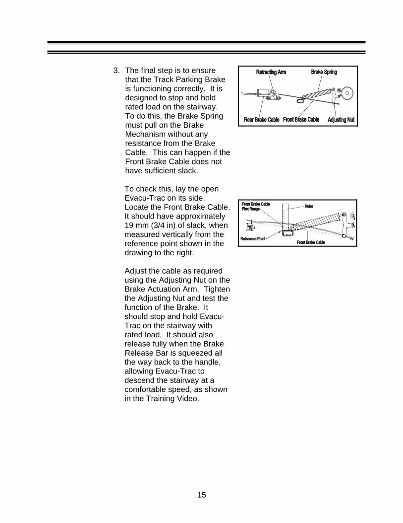
3. The final step is to ensure
that the Track Parking Brake is functioning correctly. It is designed to stop and hold rated load on the stairway. To do this, the Brake Spring must pull on the Brake Mechanism without any resistance from the Brake Cable. This can happen if the Front Brake Cable does not have sufficient slack.
To check this, lay the open Evacu-Trac on its side. Locate the Front Brake Cable. It should have approximately 19 mm (3/4 in) of slack, when measured vertically from the reference point shown in the drawing to the right. Adjust the cable as required using the Adjusting Nut on the Brake Actuation Arm. Tighten the Adjusting Nut and test the function of the Brake. It should stop and hold Evacu-Trac on the stairway with rated load. It should also release fully when the Brake Release Bar is squeezed all the way back to the handle, allowing Evacu-Trac to descend the stairway at a comfortable speed, as shown in the Training Video.
15

LUBRICATION
Evacu-Trac does not require any lubrication. Do not apply oil or grease to any parts or surfaces. This may attract dust and dirt. It may also get onto the track surfaces and brake mechanism.
CAUTION:
Do not apply any form of lubricant to Evacu-Trac.
Ensure tracks are kept free of oil.
SPARE PARTS
It is very unlikely you will need replacement parts for your Evacu-Trac. However, should parts be required contact your authorized Evacu-Trac dealer or Garaventa. For your reference, a short list of serviceable parts is shown below. A detailed parts drawing is shown on the next page. Please refer to the ID # and Item # when ordering parts.
ID # Item # Description Qty/per 21 12445 Body fabric,E/T,CD-7 1 22 12444 Leg fabric,E/T,CD-7 1 23 12690 Foam, Leg Rest,E/T,CD-7 1 24 12691 Foam, Head Rest,E/T,CD-7 1 64 12692 Damper,Oil,E/T,CD-7 1 68 12693 Ring,Snap,Front,E/T,CD-7 2 69 12483 Tread,Rubber,E/T,CD-7 2 70 12695 Spring, Return, Brake,E/T,CD-7 1 76 12694 Ring,Snap,Rear,E/T,CD-7 4 78 12696 Spring,Wheel,Idler,E/T,CD-7 2
N/A 12443 Paint,Touch-up, (Lime-Green) N/A
16

Evacu-Trac CD7 Parts Identification
17

6 Specifications
Evacu-Trac Load Capacity........................................................................136 kg (300 lbs)
Weight ...................................................................................20.7 kg (46 lbs)
Descent Speed ...........0.67 m/sec. (2.2 ft./sec.) to 1.22 m/sec. (4.0 ft./sec.) Descent speed will vary based on passenger weight, track tension, use of the hand brake and stair angle
Speed Control……by hydraulic governor and manually released hand brake
Maximum Stair Angle ................................................................................40º
Dimensions (operating): Length ......................................................................... 1310 mm (51.6 in) Width............................................................................. 426 mm (16.8 in) Height ............................................................................ 810 mm (31.9 in)
Dimensions (folded): Length ......................................................................... 1100 mm (43.3 in) Width ............................................................................. 426 mm (16.8 in) Height ............................................................................ 270 mm (10.6 in)
Patents: U.S. ............................................................................................ 5797606 Canada ....................................................................................... 2190427
Surface-Mount Storage Cabinet
Dimensions: Height .......................................................................... 1151 mm (45.3 in) Width ............................................................................. 508 mm (20.0 in) Depth ............................................................................ 279 mm (11.0 in)
18
7 Warranty
Garaventa warrants to the original purchaser that the Evacu-Trac CD7 is to be free of defects in materials and workmanship under normal use and service for a period of fifteen (15) years (excluding consumable components) from the date of purchase.
Consumable components (rubber tracks, brake components, soft materials, etc…) are warranted to be free of defects in materials and workmanship under normal use and service for a period of 2 (two) years from the date of purchase.
This Warranty does not extend to any Evacu-Trac unit which has been subjected to misuse, neglect, accident, modifications, or damage resulting from fire, lightning, water, bio/chemical or other evacuation hazard or used in violation of the instructions furnished, nor units repaired or altered by other than an authorized dealer.
Garaventa’s liability hereunder is limited to repair and replacement only at Garaventa’s sole discretion. Transportation charges are not covered. Garaventa accepts no liability for any loss or damage resulting from the use or misuse of an Evacu-Trac, whether such loss or damage is direct, indirect or consequential.
All other express or implied warranties, statutory or otherwise, are excluded.
WARRANTY REGISTRATION The above warranty is valid to the original purchaser. Proof of purchase showing the purchase date is required to determine warranty period.
A postage-paid warranty registration card is enclosed with this Owner’s Manual. Please complete and return the card within ten days of purchase.
Thank you for purchasing your Evacu-Trac CD7!
19
tdejaray
Typewritten Text
tdejaray
Typewritten Text
tdejaray
Typewritten Text
tdejaray
Typewritten Text