GARAGE DOOR OPENER Model 3800P - LiftMaster€ Complete the following test to make sure your...
36
Owner’s Manual ■ Please read this manual and the enclosed safety materials carefully! ■ Fasten the manual near the garage door after installation. ■ The door WILL NOT CLOSE unless The Protector System ® and cable tension monitor are connected and properly aligned. ■ Periodic checks of the opener are required to ensure safe operation. ■ The model number label is located behind the hinged door of your opener. GARAGE DOOR OPENER Model 3800P For Residential Use Install On Sectional Doors With Torsion Assemblies Only The Chamberlain Group, Inc. 845 Larch Avenue Elmhurst, Illinois 60126-1196 www.liftmaster.com ® C o m p a t i b l e w i t h S e e P a g e 1 3 f o r D e t a i l s
Transcript of GARAGE DOOR OPENER Model 3800P - LiftMaster€ Complete the following test to make sure your...

Owner’s Manual■ Please read this manual and the enclosed safety materials carefully!
■ Fasten the manual near the garage door after installation.
■ The door WILL NOT CLOSE unless The Protector System® and cable tension monitor areconnected and properly aligned.
■ Periodic checks of the opener are required to ensure safe operation.
■ The model number label is located behind the hinged door of your opener.
GARAGE DOOR OPENERModel 3800P
For Residential Use
Install On Sectional Doors WithTorsion Assemblies Only
The Chamberlain Group, Inc.845 Larch AvenueElmhurst, Illinois 60126-1196www.liftmaster.com
®
Com
patible with
See Page 13 for D
etails

2
INTRODUCTIONSafety Symbol Review and Signal Word Review
When you see these Safety Symbols and Signal Words onthe following pages, they will alert you to the possibility ofserious injury or death if you do not comply with thewarnings that accompany them. The hazard may comefrom something mechanical or from electric shock. Readthe warnings carefully.
When you see this Signal Word on the following pages, itwill alert you to the possibility of damage to your garagedoor and/or the garage door opener if you do not complywith the cautionary statements that accompany it. Readthem carefully.
This garage door opener has been designed and tested to offer safe service provided it is installed, operated,maintained and tested in strict accordance with the instructions and warnings contained in this manual.
Mechanical
Electrical
Introduction 2-5Safety symbol review and signal word review . . . . . . . .2Planning . . . . . . . . . . . . . . . . . . . . . . . . . . . . . . . . . . . . .3Preparing your garage door . . . . . . . . . . . . . . . . . . . . . .4Tools . . . . . . . . . . . . . . . . . . . . . . . . . . . . . . . . . . . . . . . .4Specifications . . . . . . . . . . . . . . . . . . . . . . . . . . . . . . . . .4Carton inventory . . . . . . . . . . . . . . . . . . . . . . . . . . . . . . .5Hardware inventory . . . . . . . . . . . . . . . . . . . . . . . . . . . . .5
Assembly 6Attach the collar to the motor unit . . . . . . . . . . . . . . . . . .6Attach mounting bracket to the motor unit . . . . . . . . . . .6
Installation 7-16Installation safety instructions . . . . . . . . . . . . . . . . . . . . .7Position the opener . . . . . . . . . . . . . . . . . . . . . . . . . . . . .7Attach the emergency release rope and handle . . . . . . .8Install the power door lock . . . . . . . . . . . . . . . . . . . . . . .8Attach the cable tension monitor (Required) . . . . . . . . . .9Install the control console . . . . . . . . . . . . . . . . . . . . . . .10Install remote light . . . . . . . . . . . . . . . . . . . . . . . . . . . . .11Electrical requirements . . . . . . . . . . . . . . . . . . . . . . . . .12Mount the battery backup unit (BBU) (not provided) . .13Install The Protector System® . . . . . . . . . . . . . . . . . .14-16
Adjustment 17-20Program the travel limits . . . . . . . . . . . . . . . . . . . . . . . .17Setting the force . . . . . . . . . . . . . . . . . . . . . . . . . . . . . .18Test the safety reversal system . . . . . . . . . . . . . . . . . . .19Test The Protector System® . . . . . . . . . . . . . . . . . . . . . .19Test cable tension monitor . . . . . . . . . . . . . . . . . . . . . .20 Test power door lock . . . . . . . . . . . . . . . . . . . . . . . . . . .20To open door manually . . . . . . . . . . . . . . . . . . . . . . . . .20
Operation 21-27Operation safety instructions . . . . . . . . . . . . . . . . . . . . .21Using your garage door opener . . . . . . . . . . . . . . . . . .21Using the wall-mounted door control . . . . . . . . . . . . . .22Using the remote control . . . . . . . . . . . . . . . . . . . . . . . .23Troubleshooting . . . . . . . . . . . . . . . . . . . . . . . . . . . . . . .23The remote control battery . . . . . . . . . . . . . . . . . . . . . .23Care of your opener . . . . . . . . . . . . . . . . . . . . . . . . . . .24Having a problem? (Troubleshooting) . . . . . . . . . . .24-25Smart Control Panel™ messages . . . . . . . . . . . . . . . . .26Diagnostic Chart . . . . . . . . . . . . . . . . . . . . . . . . . . . . . .27
Programming 28-30To add or reprogram a hand-held remote control . . . . .28To erase all codes from motor unit memory . . . . . . . . .283-Button remote . . . . . . . . . . . . . . . . . . . . . . . . . . . . . . .28To add, reprogram or change a keyless entry PIN . . . . . . . . . . . . . . . . . . . . . . . . . . . .29Programming work light or additional work light . . . . . .30
Repair Parts 31-32Installation parts . . . . . . . . . . . . . . . . . . . . . . . . . . . . . .31Motor unit assembly parts . . . . . . . . . . . . . . . . . . . . . . .32
Accessories 33Operator Notes 34-35Repair Parts and Service 36Warranty 36
TABLE OF CONTENTS

Safety Reversing Sensor
SafetyReversingSensor
Torsion Spring
Motor unit
Wall-mountedDoor ControlAccess Door
Gap between floor and bottom of door must not exceed 1/4" (6 mm).
Power Door Lock
Cable Tension Monitor Remote Light
Drum
3
PlanningSurvey your garage area to see if any of the conditionsbelow apply to your installation. Additional materials maybe required. You may find it helpful to refer back to thispage as you proceed with the installation of your opener.
Depending on your requirements, there are severalinstallation steps which may call for materials or hardwarenot included in the carton.
This opener is compatible with:• Doors that use a torsion bar, springs and a door no
more than 14' (4.2 m) high.
• 4"-6" (10 cm - 15 cm) drums, not to be used on tapereddrums over 6" (15 cm).
• High lift and standard lift sectional doors up to 14' (4.2 m) high.
• Doors up to 18' (5.4 m) wide.
• Doors up to 180 sq. ft. (16.7 sq. m).
• 1" (2.5 cm) torsion bar only.
• Review or inspect proposed installation area. Openercan be installed on left or right side of door. Select theside that meets the requirements listed below.
- Must have minimum of 2-1/2" (6.4 cm) between thegarage wall and the center of the torsion bar.
- Must have minimum of 3" (7.6 cm) between the ceilingand the center of torsion bar.
- Must have minimum of 8" (20.3 cm) between the sidegarage wall (or obstruction) and the end of torsion bar.
• The torsion bar must extend at least 1" to 5"(2.5 cm to 12 cm) past the bearing plate.
• An electric outlet is required within 6' (1.8 m) of theinstallation area. If outlet does not exist, contact aqualified electrician.
• Depending upon garage construction, extensionbrackets or wood blocks may be needed to install safetyreversing sensors.
• Alternate floor mounting of the safety reversing sensorswill require hardware not provided.
• A model 475LM EverChargeTM Battery Backup System isstrongly recommended if there is no access door to thegarage, as this opener cannot be used in conjunctionwith an external emergency release mechanism.
• Any gap between the floor and the bottom of the doormust not exceed 1/4" (6 mm). Otherwise the safetyreversal system may not work properly.
NOTE: Inspect the torsion bar while the door is raised andlowered. It is important that there is no noticeablemovement up and down or left and right. If this type ofmovement is not corrected, life of this opener will begreatly reduced.

4
Preparing your Garage Door Before you begin:• Disable locks. • Remove any ropes connected to garage door. • Complete the following test to make sure your garage
door is balanced and is not sticking or binding:
1. Lift the door about halfway as shown. Release thedoor. If balanced, it should stay in place, supportedentirely by its springs.
2. Raise and lower the door to see if there is anybinding or sticking.
If your door binds, sticks or is out of balance, call atrained door systems technician.
3. Verify equal cable tension on each side of door.Cable tension should remain equal during the entiretravel of the door. To prevent damage to garage door and opener:
• ALWAYS disable locks BEFORE installing and operating theopener.
• ONLY operate garage door opener at 120V, 60 Hz to avoidmalfunction and damage.
To prevent possible SERIOUS INJURY or DEATH:• ALWAYS call a trained door systems technician if garage
door binds, sticks or is out of balance. An unbalanced garagedoor may not reverse when required.
• NEVER try to loosen, move or adjust garage door, doorsprings, cables, pulleys, brackets or their hardware, ALL ofwhich are under EXTREME tension.
• Disable ALL locks and remove ALL ropes connected togarage door BEFORE installing and operating garage dooropener to avoid entanglement.
Tools neededDuring assembly, installation and adjustment of theopener, instructions will call for hand tools as illustratedbelow.
Pliers Wire Cutters
Claw Hammer
Screwdriver
Adjustable End Wrench1/4", 5/16" & 3/8" Socketsand Wrench with 6" Extension
Drill Tape Measure
21
Stepladder
Pencil
3/16" and 1/8"Hex Key Wrench
Needle Nose Pliers
5/32", 3/16", 5/16" and 3/4" Drill Bits
Sectional Door
Torque Meter (not shown)

5
2-Conductor Bell WireWhite & White/Red
Safety LabelsandLiterature
Remote ControlVisor Clip
Mounting Bracket
SECURITY✚®
3-Button Remote Control (1)
The Protector System®
(2) Safety Reversing Sensors(1 Sending Eye and 1 Receiving Eye)with 2-Conductor White & White/Black Bell Wire attached
Safety SensorBracket (2)
Motor Unit
Collar with Screws
Cable TensionMonitor with 2-ConductorGreen/White Bell Wires
Power Door Lock 2-Conductor White & White/Black Bell Wire with Connector
Remote Light (Opener Light) with Hardware BagSmart Control Panel™
LOCK
L GI HT
Carton InventoryYour garage door opener is packaged in one carton whichcontains the motor unit and the parts illustrated below.Note that accessories will depend on the model
purchased. If anything is missing, carefully check thepacking material.
Hardware InventoryINSTALLATION HARDWAREHex Screw #14-10x1-7/8" (4)
Screw #6x-1-1/4" (2)
Machine Screw #6x1" (2)
Carriage Bolt 1/4"-20x1/2" (2)
Wing Nut 1/4"-20 (2)
Pan Head Screw 1/4"-20x1/2" (2)
Hex Head Screw #8x1" (2)
Self Tapping Screw #10-32 (2)
Drywall Anchor (2)
Drywall Anchor (Screw-In) (2)
Handle
Rope
Insulated Staples (30)
Lock Template
Model 373P (1)

ASSEMBLY STEP 1Attach the Collar to the Motor UnitTo avoid installation difficulties, do not run the garagedoor opener until instructed to do so.• Loosen the collar screws.
• Attach collar to either the left or the right side of themotor unit. Ensure that the collar is seated all the wayon motor shaft until stop is reached (Figure 1).
• Position the collar so that the screws are facing up(accessible when attached to the torsion bar).
• Tighten both sides of collar screws equally to securecollar to the motor unit (12-14 ft./lbs. of torque) (Figure 2).
NOTE: For most installations the screws should be facingup for easy access. Do not tighten set screws untilindicated.
6
Collar Screw
Collar Screw
Set Screw
ASSEMBLY STEP 2Attach Mounting Bracket to Motor Unit• Loosely attach slotted side of mounting bracket to the
same side of the motor unit as the collar, usingself-threading screws provided.
NOTE: Do not tighten until instructed. Illustrations shownare for left side installation.
Socket Wrench
Figure 1
RIGHT WRONG
Figure 2
Screw#10-32
HARDWARE SHOWN ACTUAL SIZE
To prevent possible SERIOUS INJURY or DEATH, the collarMUST be properly tightened. The door may not reversecorrectly or limits may be lost due to collar slip.

7
INSTALLATION
INSTALLATION STEP 1Position the OpenerNOTE: For additional mounting options see accessoriespage.
1. Close the garage door completely.
2. Slide the opener with collar over the end of the torsionbar. Ensure that the collar does not touch the bearingplate. Check to make sure the mounting bracket islocated on a solid surface such as wood, concrete ordoor/flag bracket. Snug collar screws to help assureproper alignment of operator. Mark the bracket holes. Itmay be necessary to cut the torsion bar if it is too longor damaged.
3. Loosen collar screws from torsion bar and remove theopener. Drill 3/16" pilot holes at the marked locations.Drill through steel plate if needed.
4. Reinstall the opener by sliding the collar over the torsionbar until pilot holes align with bracket. Securely tightencollar screws that attach to the torsion bar to 12-14ft./lbs. of torque. Securely tighten both set screws firmly,without damaging the motor unit.
5. Fasten bracket securely with 14-10x1-7/8" screws.Tighten all mounting bracket hardware.
NOTE: The motor unit does not have to be flush to wall.
6. Use a staple to secure the antenna wire to preventantenna from being entangled in a door roller.
To prevent possible SERIOUS INJURY or DEATH:• Concrete anchors MUST be used if mounting bracket into
masonry.• NEVER try to loosen, move or adjust garage door, springs,
cables, pulleys, brackets or their hardware, ALL of which areunder EXTREME tension.
• ALWAYS call a trained door systems technician if garagedoor binds, sticks or is out of balance. An unbalancedgarage door might not reverse when required.
• Operator MUST be mounted at a right angle to the torsionbar to avoid premature wear on the collar.
Motor unit
Staple
Torsion Bar
14-10x1-7/8" Hex Screw
HARDWARE SHOWN ACTUAL SIZE
IMPORTANT INSTALLATION INSTRUCTIONS
To reduce the risk of SEVERE INJURY or DEATH:
WARNING
WARNING
WARNINGWARNING
1. READ AND FOLLOW ALL INSTALLATION WARNINGS ANDINSTRUCTIONS.
2. Install garage door opener ONLY on properly balanced andlubricated garage door. An improperly balanced door maynot reverse when required and could result in SEVEREINJURY or DEATH.
3. ALL repairs to cables, spring assemblies and other hardwareMUST be made by a trained door systems technicianBEFORE installing opener.
4. Disable ALL locks and remove ALL ropes connected togarage door BEFORE installing opener to avoidentanglement.
5 Mount emergency release handle no higher than 6 feet (1.83 m) above floor.
6. NEVER connect garage door opener to power source untilinstructed to do so.
7. NEVER wear watches, rings or loose clothing while installingor servicing opener. They could be caught in garage door oropener mechanisms.
8. Install wall-mounted garage door control:• within sight of the garage door. • out of reach of children at minimum height of 5 feet
(1.5 m).• away from ALL moving parts of the door.
9. Place entrapment warning label on wall next to garage doorcontrol.
10. Place manual release/safety reverse test label in plain viewon inside of garage door.
11. Upon completion of installation, test safety reversal system.Door MUST reverse on contact with a 1-1/2" (3.8 cm) highobject (or a 2x4 laid flat) on the floor.

StaplesLock Screw1/4-20 x 1/2" (2)
HARDWARE SHOWN ACTUAL SIZE
Approx. 3" (7.6 cm)
Lock Template
Roller
Garage Door Track
TOP
DRILL 5/16"
DRILL 3/4"
DRILL 5/16"
13
2A
25
05
TOP
DRILL 5/16"
DRILL 3/4"
DRILL 5/16"
13
2A
25
05
Figure 1INSTALLATION STEP 3Install Power Door LockThe lock is used to prevent the garage door frombeing manually opened once the door is fully closed.1. Select a door roller to mount the lock above. Check for
clearance. If possible select a roller on the same side ofthe door as the motor unit. The second roller up fromthe bottom is ideal in most installations.
2. Ensure rail surface is clean and adhere lock templatewith bottom edge just above the highest point on theroller (Figure 1).
3. Drill holes as marked on the template.
4. Fasten power door lock to the outside of the garagedoor track with hardware provided.
5. Run bell wire up wall to motor unit. Use insulatedstaples to secure wire in several places.
6. Plug connector into the motor unit (Figure 2).
NOTE: Lock must be mounted within 10' of the powerhead.
NOTICE
OverhandKnot
EmergencyRelease Handle
OverhandKnot
Rope
Motor Unit
Emergency Release Cable
To prevent possible SERIOUS INJURY or DEATH from a fallinggarage door:• If possible, use emergency release handle to disengage door
ONLY when garage door is CLOSED. Weak or broken springsor unbalanced door could result in an open door fallingrapidly and/or unexpectedly.
• NEVER use emergency release handle unless garagedoorway is clear of persons and obstructions.
INSTALLATION STEP 2Attach the Emergency Release Ropeand Handle• Thread one end of the rope through the hole in the top
of the red handle so “NOTICE” reads right side up asshown. Secure with an overhand knot at least 1" (2.5 cm) from the end of the rope to prevent slipping.
• Thread the other end of the rope through the loop in theemergency release cable.
• Adjust rope length so the handle is no higher than 6'(1.83 m) above the floor. Secure with an overhand knot.
NOTE: If it is necessary to cut the rope, heat seal the cutend with a match or lighter to prevent unraveling.
Figure 2
8

WHT/GRN
To insert or release wire, push in tab with screwdriver tip
Cable Tension Monitor
7/16" (11mm)
Strip wire 7/16" (11mm)
WHT/GRN
Cable Tension Monitor
Cable Tension Monitor Roller
Cable
2"-6"(5 cm-15 cm)
Drum
Torsion Bar
Opener
1/8"-1/4"(3 mm-6 mm)
With Door ClosedPreferred Orientation
Figure 1
#8 Hex Head Screw (2)
Screw #6 (2) Wall Anchor (2)
Staples
HARDWARE SHOWN ACTUAL SIZE
Figure 3
INSTALLATION STEP 4Attach the Cable Tension Monitor(Required)This opener comes standard with the cable tensionmonitor. It is supplied as a device to monitor thecables for ANY slack that may occur and will reversethe door when excessive slack is detected, eliminatingservice calls.The cable tension monitor MUST be connected andproperly installed before the garage door opener willmove in the down direction.NOTE: The cable tension monitor is shipped for left sideinstallation. It is preferred that the cable tension monitorbe installed on the same side of the door as the opener.If required, it can be mounted on the opposite side of door.Remove the snap-ring holding the roller in place andreassemble it on the opposite side of the cable tensionmonitor.
1. Position the cable tension monitor as shown (Figures 1 and 2). The cable tension monitor should belocated as close to the drum as possible.
NOTE: There must be no obstructions in the installationarea that prevent the cable tension monitor or the cableitself from closing completely when slack is detected.
2. Make sure cable tension monitor is located over a woodsupport member.
NOTE: If the cable tension monitor can not be mountedinto wood with the lag screws provided, it can be mountedinto 1/2" or greater drywall using the wall anchors (2) andthe #8 hex head screws (2) provided in the hardware bag.
3. Mark and drill 3/16" pilot holes for screws (pilot holesare not required for anchors).
4. Attach the cable tension monitor to the wall using thehardware provided. Make sure that the roller is on top ofthe cable.
5. Run bell wire to motor unit. Use insulated staples tosecure wire in several places.
6. Connect bell wire to the green quick-connect terminals(polarity is not important) (Figure 3).
NOTE: Cable must have tension through entire travel.Make sure there is no slack in cable on opposite side ofgarage door during normal operation. If this conditionexists, adjust cables as required.
3/4" Min.(18 mm Min.)
WallDrum
Cable
Figure 2
9

INSTALLATION STEP 5Install the Door ControlLocate door control within sight of door, at a minimumheight of 5' (1.5 m) where small children cannot reach,away from moving parts of door and door hardware. Ifinstalling into drywall, drill 5/32" holes and use the anchorsprovided. For pre-wired installations (as in new homeconstruction), it may be mounted to a single gang box(Figure 1).
NOTE: The functional temperature range of the doorcontrol is between -20°C (-4°F) and +50°C (+122°F).Scroll speed of display is slower at lower temperaturesalthough the door control remains fully functional.
CAUTION: Continuous exposure of the door control totemperatures below -22°F (-30°C) may damage the LCDscreen.
SPECIAL NOTE: Only one 398LM can be connected toeach garage door opener. If additional wall controls aredesired to operate the same garage door opener, it isrecommended to use model 378LM wireless wall controlas the secondary door control.
1. Strip 7/16" (11 mm) of insulation from one end of bellwire and connect to the two screw terminals on back ofdoor control by color: white wire to the W (2) andwhite/red wire to the R (1) (Figure 2).
2. Remove push bar cover by gently prying at thelower/middle portion of the cover with a small flat-headscrewdriver. Fasten with 6AB x 1-1/4" self-tappingscrews (drywall installation) or 6-32 x 1" machinescrews (into gang box) as follows:
• Install bottom screw, allowing 1/8" (3 mm) to protrudeabove wall surface.
• Position bottom of door control on screw head andslide down to secure. Adjust screw for snug fit.
• Drill and install top screw with care to avoid crackingplastic housing. Do NOT overtighten.
• Replace cover by inserting top tabs first and then snapcover in place.
3. (For standard installations ONLY) Run bell wire upwall and across ceiling to motor unit. Use insulatedstaples to secure wire in several places. Do NOT piercewire with a staple, creating a short or open circuit.
4. Strip 7/16" (11 mm) of insulation from end of bell wire.Connect bell wire to the quick-connect terminals on themotor unit: white to white and white/red to red(Figure 3).
NOTE: DO NOT connect the power and operate theopener at this time. The door will travel to the full openposition but will not return to the close position until thesensor beams are connected and properly aligned. Seepage 14.
WHT/RED
WHTDoor ControlConnections
To insert or release wire, push in tab with screwdriver tip
7/16" (11 mm)
Strip wire 7/16" (11 mm)
To prevent possible SERIOUS INJURY or DEATH fromelectrocution:• Be sure power is not connected BEFORE installing door control.• Connect ONLY to 24 VOLT low voltage wires. To prevent possible SERIOUS INJURY or DEATH from a closinggarage door:• Install door control within sight of garage door, out of reach of
children at a minimum height of 5 feet (1.5 m) and away fromALL moving parts of door.
• NEVER permit children to operate or play with door control pushbuttons or remote controls.
• Activate door ONLY when it can be seen clearly, is properlyadjusted and there are no obstructions to door travel.
• ALWAYS keep garage door in sight until completely closed.NEVER permit anyone to cross path of closing garage door.
Drywall Anchors
InsulatedStaples
Screw 6ABx1-1/4"(standard installation)
Screw 6-32x1" (pre-wired)
HARDWARE SHOWN ACTUAL SIZE
Figure 3
10
Push Bar
Light Button
LockButton
DoorControlTerminalScrews
(BACK VIEW)
W2
R1
2-ConductorBell Wire
LOCK
LOCK
Figure 2
PRE-WIRED INSTALLATIONREMOVE & REPLACE COVER
To Replace Insert Top Tabs First
Push Bar Cover
24 Volt Bell WireLOCKLIGHT
LOCKLIGHT
Figure 1

11
INSTALLATION STEP 6Install the LightThe remote light (opener light) is designed to plug directlyinto a standard 120V outlet.
1. Install the hinge and latch clips. Clips slide in betweenthe metal plate and the plastic housing on each side ofthe light base (Figure 1).
2. Select an appropriate location on the ceiling to mountthe light within 6' (1.8 m) of an electrical outlet so thatthe cord and light are away from moving parts.
3. Install the ceiling mount plate with the screws provided.Leave 1/8" (3.1 mm) of the thread exposed between theceiling and the screw head (Figure 2).
NOTE: If installing remote light (opener light) on drywalland a ceiling joist can not be located, use wall anchorsprovided. No pilot hole is required for wall anchors.
4. Determine the length of power cord needed to reach thenearest outlet. Wind any excess cord around cordretainer on the top side of the light base.
5. Install the light base by pushing onto the screws andturning the base clockwise to lock the light in place.
6. Install two Type A19 incandescent or compactfluorescent bulbs. 100 watt maximum per bulb,200 watts total.
7. Install the light lens by hooking one end of the lens overthe hinge and pressing up on the other end to latch intoplace (Figure 3).
8. Plug in the light to outlet.
NOTE: Light will not operate until the unit is activated.
To prevent possible OVERHEATING of the endpanel or lightsocket:• DO NOT use short neck or specialty light bulbs.• DO NOT use halogen bulbs. Use ONLY incandescent.To prevent damage to the opener:• DO NOT use bulbs larger than 100W.• ONLY use A19 size bulbs.
Wall Anchors
Scews
Cord Retainer
Figure 2
Hinge Clip
Latch Clip
Metal Plate
PlasticHousing
Light Base
Light ClipScrew
Light Clip ScrewFigure 1
LightLens
100 Watt (max)
Figure 3
Screw #6x1" (2)
W ll A h (2)
Light Clip Screw#4-20 X 7/16" (2)
HARDWARE SHOWN ACTUAL SIZE
IMPORTANT SAFETY INSTRUCTIONS
To reduce the risk of SEVERE INJURY or DEATH:
WARNING
WARNING
WARNINGWARNING
1. This portable luminaire has a polarized plug (one blade iswider than the other) as a feature to reduce the risk ofelectric shock.
2. This plug will fit in a polarized outlet ONLY one way. 3. If the plug does not fit fully in the outlet, reverse the plug.4. If it still does not fit, contact a qualified electrician.
5. NEVER use with an extension cord unless plug can be fullyinserted.
6. Do not alter the plug.7. Light is intended for ceiling mount and indoor applications
ONLY.

12
INSTALLATION STEP 7Electrical RequirementsTo avoid installation difficulties, do not run the openerat this time.To reduce the risk of electric shock, your garage dooropener has a grounding type plug with a third groundingpin. This plug will only fit into a grounding type outlet. Ifthe plug doesn't fit into the outlet you have, contact aqualified electrician to install the proper outlet.
If permanent wiring is required by your local code,refer to the following procedure.To make a permanent connection through the 7/8" hole inthe back of the motor unit (according to local code):
• Remove the opener from the torsion bar, remove coverscrews and set the cover aside.
• Remove the attached green ground terminal.
• Cut black and white wires and strip away 1/2" (1.3 cm)of insulation, 3" (7.6 cm) before spade terminals.
• Remove the power cord from unit.
• Install a 90o conduit or flex cable adapter to the 7/8"hole. Reinstall opener to torsion bar.
• Run wires through conduit, cut to proper length and stripinsulation.
• Attach with wire nuts provided.
• Properly secure wire under plastic ties so that wire doesnot come in contact with moving parts.
• Reinstall the cover.
To avoid installation difficulties, do not run the openerat this time.
RIGHT WRONG
Black WireFrom Power Cord
White WireFrom Power Cord
Ground Tab
Green Ground Screw
Ground Wire
Flexible conduit
PERMANENT WIRING CONNECTION
90˚ Connector
Green Wire White Wire
Black Wire
PERMANENT WIRING CONNECTION
To prevent possible SERIOUS INJURY or DEATH fromelectrocution or fire:• Be sure power is not connected to the opener, and
disconnect power to circuit BEFORE removing cover toestablish permanent wiring connection.
• Garage door installation and wiring MUST be in compliancewith ALL local electrical and building codes.
• NEVER use an extension cord, 2-wire adapter or change plugin any way to make it fit outlet. Be sure the opener isgrounded.

13
INSTALLATION STEP 8Mount the Battery Backup Unit (BBU)(not provided)If the optional 475LM battery backup unit is part of thisinstallation it should be installed at this time.
• The BBU can be mounted to either the ceiling or a wallwithin 3' (.9 m) of the motor unit.
• Position the BBU as desired to a structural support(ceiling joist or wall stud).
• Attach the BBU to the support using the mounting holeson either side of the BBU.
• Secure the BBU using the 1-1/2" lag screws (2) providedwith the BBU unit.
• Connect the BBU cord into the connector on the bottomof the motor unit.
• Follow all instructions included with the 475LM unit totest for proper operation and testing of the BBU. BBU Cord
Connector
475LM BatteryBackup Unit

14
Invisible Light BeamProtection Area
Safety Reversing Sensor6" (15 cm) max. above floor
Safety Reversing Sensor6" (15 cm) max. above floor
Facing the door from inside the garage
INSTALLATION STEP 9Install The Protector System®
The safety reversing sensor must be connected andaligned correctly before the garage door opener willmove in the down direction. This is a required safetydevice and cannot be disabled.
IMPORTANT INFORMATION ABOUT THE SAFETYREVERSING SENSORWhen properly connected and aligned, the safetyreversing sensor will detect an obstacle in the path of itselectronic beam. The sending eye (with an amber indicatorlight) transmits an invisible light beam to the receiving eye(with a green indicator light). If an obstruction breaks thelight beam while the door is closing, the door will stop andreverse to full open position, and the opener lights willflash 10 times.
The units must be installed inside the garage so that thesending and receiving eyes face each other across thedoor, no more than 6" (15 cm) above the floor. Either canbe installed on the left or right of the door as long as thesun never shines directly into the receiving eye lens.
The mounting brackets are designed to clip onto the trackof sectional garage doors without additional hardware.
If it is necessary to mount the units on the wall, thebrackets must be securely fastened to a solid surfacesuch as the wall framing. Extension brackets (seeaccessories) are available if needed. If installing inmasonry construction, add a piece of wood at eachlocation to avoid drilling extra holes in masonry ifrepositioning is necessary.
The invisible light beam path must be unobstructed. Nopart of the garage door (door tracks, springs, hinges,rollers or other hardware) may interrupt the beam whilethe door is closing.
Be sure power is not connected to the garage door openerBEFORE installing the safety reversing sensor.To prevent SERIOUS INJURY or DEATH from a closing garagedoor:• Correctly connect and align the safety reversing sensor. This
required safety device MUST NOT be disabled.• Install the safety reversing sensor so beam is NO HIGHER
than 6" (15 cm) above garage floor.

15
DOOR TRACK MOUNT (RIGHT SIDE)
IndicatorLight
Lens
Lip
SensorBracket
DoorTrack
FLOOR MOUNT (RIGHT SIDE)
WALL MOUNT (RIGHT SIDE)
IndicatorLight
SensorBracket
Lens
ExtensionBracket(See Accessories)
Inside
Garage
Wall
(Provided withExtension Bracket)
(Provided withExtension Bracket)
Figure 1
Figure 2
Figure 3
Figure 4
WALL MOUNT (RIGHT SIDE)
Attach with Concrete Anchors(Not Provided)
Inside
Garage
Wall
SensorBracket
LensIndicatorLight
Inside
Garage
Wall
IndicatorLight Sensor
Bracket
Lens
Lag Screws(Not Provided)
Fasten Wood Block to Wall withLag Screws (Not Provided)
INSTALLING THE BRACKETS
Be sure power to the opener is disconnected. Installand align the brackets so the safety reversing sensors willface each other across the garage door, with the beam nohigher than 6" (15 cm) above the floor. They may beinstalled in one of three ways,as follows.
Garage door track installation (preferred)(Figure 1):• Slip the curved arms over the rounded edge of each
door track, with the curved arms facing the door. Snapinto place against the side of the track. It should lie flush,with the lip hugging the back edge of the track, as shownin Figure 1.
If your door track will not support the bracket securely, wallinstallation is recommended.
Wall installation (Figure 2 and 3):• Place the bracket against the wall with curved arms
facing the door. Be sure there is enough clearance forthe sensor beam to be unobstructed.
• If additional depth is needed, an extension bracket (See Accessories) or wood blocks can be used.
• Use bracket mounting holes as a template to locate anddrill (2) 3/16" diameter pilot holes on the wall at eachside of the door, no higher than 6" (15 cm) above thefloor.
• Attach brackets to wall with lag screws (Not Provided).
• If using extension brackets or wood blocks, adjust rightand left assemblies to the same distance out from themounting surface. Make sure all door hardwareobstructions are cleared.
Floor installation (Figure 4):• Use wood blocks or extension brackets (See
Accessories) to elevate sensor brackets so the lenseswill be no higher than 6" (15 cm) above the floor.
• Carefully measure and place right and left assemblies atthe same distance out from the wall. Be sure all doorhardware obstructions are cleared.
• Fasten to the floor with concrete anchors as shown.
Wing Nut1/4"-20
StaplesCarriage Bolt1/4"-20x1/2"
HARDWARE SHOWN ACTUAL SIZE

16
Invisible Light BeamProtection AreaSensor
SensorSafety Reversing Sensor
Bell Wire
Bell Wire
Motor unit
Safety Reversing Sensor
Power Door Lock
Quick-Connect Terminals
WHT/BLK
WHT
WHT/RED
WHT
Sensor Connections
To Power Door Lock
To CableTension Monitor
To Door Control
Connect Wire to Quick-Connect Terminals
Carriage Bolt 1/4"-20x1/2"
Lens
Wing Nut1/4"-20
Figure 5
Figure 6
MOUNTING AND WIRING THE SAFETY REVERSINGSENSORS• Slide a 1/4"-20x1/2" carriage bolt head into the slot on
each sensor. Use wing nuts to fasten safety reversingsensors to brackets, with lenses pointing toward eachother across the door. Be sure the lens is not obstructedby a bracket extension (Figure 5).
• Finger tighten the wing nuts.
• Run the wires from both safety reversing sensors to theopener. Use insulated staples to secure wire to wall and ceiling.
• Strip 7/16" (11 mm) of insulation from each set of wires.Separate white and white/black wires sufficiently toconnect to the opener quick-connect terminals: white towhite and white/black to grey (Figure 6).
ALIGNING THE SAFETY REVERSING SENSORS• Plug in the opener. The indicator lights in both the
sending and receiving eyes will glow steadily if wiringconnections and alignment are correct.
The sending eye amber indicator light will glow regardlessof alignment or obstruction. If the green indicator light inthe receiving eye is off, dim, or flickering (and the invisiblelight beam path is not obstructed), alignment is required.
• Loosen the sending eye wing nut and readjust, aimingdirectly at the receiving eye. Lock in place.
• Loosen the receiving eye wing nut and adjust the safetyreversing sensor until it receives the sender’s beam.When the green indicator light glows steadily, tighten thewing nut.
TROUBLESHOOTING THE SAFETY REVERSINGSENSORS1. If the sending eye indicator light does not glow steadily
after installation, check for:
• Electric power to the opener.
• A short in the white or white/black wires. These canoccur at staples, or at opener connections.
• Incorrect wiring between safety reversing sensors andopener.
• A broken wire.
2. If the sending eye indicator light glows steadily but thereceiving eye indicator light doesn't:
• Check alignment.
• Check for an open wire to the receiving eye.
3. If the receiving eye indicator light is dim, realign either sensor.
NOTE: When the invisible beam path is obstructed ormisaligned while the door is closing, the door will reverse.If the door is already open, it will not close.The remote lights will blink 10 times. (If bulbs are notinstalled, 10 clicks can be heard.) See page 11.

17
To prevent damage to vehicles, be sure fully open doorprovides adequate clearance.
BLACK
PURPLE
Push and holduntil the door is at desired UPposition
Figure 2
Figure 3
Push eitherbutton to stopdoor at desiredDOWN position
BLACK
PURPLE
Figure 4
or
LOCK
LIGHT
Without a properly installed safety reversal system, persons(particularly small children) could be SERIOUSLY INJURED orKILLED by a closing garage door.• NEVER learn forces or limits when door is binding or
sticking. Repair door first.• Incorrect adjustment of garage door travel limits will
interfere with proper operation of safety reversal system. • After ANY adjustments are made, the safety reversal system
MUST be tested. Door MUST reverse on contact with 1-1/2"high (3.8 cm) object (or 2x4 laid flat) on floor.
ADJUSTMENT STEP 1Program the Travel LimitsTravel limits regulate the points at which the door willstop when moving up or down. Follow the stepsbelow to set the limits.
To program the travel limits:Adjust the position of the door by using the black andpurple buttons. Black moves the door UP (open) andpurple moves the door DOWN (close).
1. Setting the UP position: Press and hold the blackbutton until the yellow indicator light starts flashingslowly then release.
2. Push and hold the black button until the door reachesthe desired UP (open) position (Figure 2).
NOTE: Check to be sure the door opens high enough foryour vehicle.
3. Push the remote control or door control (Figure 3). Thissets the UP (open) limit and begins closing the door.
NOTE: Excessive movement of the motor unit will causepremature wear. See Troubleshooting section.
4. Immediately when the door begins to move down, pressand release either the black or purple button. This willstop the door.
5. Setting the DOWN position: Push and hold the purplebutton until the door reaches the desired DOWN(closed) position (Figure 4).
6. Once the door is closed, check for proper pressure onthe door (you should be able to manually push the doordown a 1/16 of an inch). If there appears to be toomuch pressure on the door, you may toggle the doorback and forth using the black and purple buttons toreach the desired position.
7. Push the remote control or the door control (Figure 3).This sets the DOWN (close) limit and should bring thedoor to the open position.
• If the opener is not stopping exactly where you wouldlike it, repeat steps 1 through 7 and program the limitsagain.
• When the unit stops in both the desired up (open) anddown (close) positions, proceed to Adjustment Step 2,Setting the Force.
PurpleButton
Indicator Light
BlackButton
Figure 1

18
ADJUSTMENT STEP 2Setting the ForceThe force setting button is located on the front panel.The force setting measures the amount of forcerequired to open and close the door.1. Locate the purple button on the unit (Figure 1).
2. Push the purple button twice to enter unit into ForceAdjustment Mode (Figure 2). The LED (Indicator Light)will flash quickly.
3. Push the remote control or door control (Figure 3). Thedoor will travel to the DOWN (close) position. Push theremote control or door control again, the door will travelto the UP (open) position. Push the remote control ordoor control a third time to send the door to the DOWN(close) position.
The LED (Indicator Light) will stop flashing when the forcehas been learned.
The unit has learned the forces required to open and closeyour door.
The door must travel through a complete cycle, UP andDOWN, in order for the force to be set properly. If the unitcannot open and close your door fully, inspect your door toinsure that it is balanced properly and is not sticking orbinding. See page 4, “Preparing your garage door.”
PurpleButton
Indicator Light Black
Button BLACK
PURPLE
Push Purple button twice to enter unit into Force Adjustment Mode
Figure 3
Figure 2Figure 1
or
LOCK
LIGHT
Without a properly installed safety reversal system, persons(particularly small children) could be SERIOUSLY INJURED orKILLED by a closing garage door.• NEVER learn forces or limits when door is binding or
sticking. Repair door first• Too much force on garage door will interfere with proper
operation of safety reversal system.• After ANY adjustments are made, the safety reversal system
MUST be tested. Door MUST reverse on contact with 1-1/2"high (3.8 cm) object (or 2x4 laid flat) on floor.

19
ADJUSTMENT STEP 3Test the Safety Reversal System
TEST• With the door fully open, place a 1-1/2" (3.8 cm) board
(or a 2x4 laid flat) on the floor, centered under thegarage door.
• Operate the door in the down direction. The door mustreverse on striking the obstruction. Upon successfulsafety reversal test proceed to Adjustment Step 4.
ADJUST• If the door stops on the obstruction, it is not traveling far
enough in the down direction. Complete AdjustmentSteps 1 and 2 Programming the Limits and Forces.
• Repeat the test.
• When the door reverses on the 1-1/2" (3.8 cm) board (or2x4 laid flat), remove the obstruction and run the openerthrough 3 or 4 complete travel cycles to test adjustment.
• If the unit continues to fail the Safety Reverse Test, callfor a trained door systems technician.
IMPORTANT SAFETY CHECK:Test the Safety Reverse System after:• Each adjustment of limits, or force controls.• Any repair to or adjustment of the garage door
(including springs and hardware).• Any repair to or buckling of the garage floor.• Any repair to or adjustment of the opener.
ADJUSTMENT STEP 4Test The Protector System®
• Press the remote control push button to open the door.
• Place the opener carton in the path of the door.
• Press the remote control push button to close the door.The door will not move more than an inch, and theopener lights will flash.
The garage door opener will not close from a remote if theindicator light in either sensor is off (alerting you to the factthat the sensor is misaligned or obstructed).
If the opener closes the door when the safetyreversing sensor is obstructed, do not operate thedoor. Call for a trained door systems technician.
1-1/2" (3.8 cm) board (or a 2x4 laid flat)
Without a properly installed safety reversal system, persons(particularly small children) could be SERIOUSLY INJURED orKILLED by a closing garage door. • Safety reversal system MUST be tested every month.• If one control (force or travel limits) is adjusted, the other
control may also need adjustment.• After ANY adjustments are made, the safety reversal system
MUST be tested. Door MUST reverse on contact with 1-1/2"(3.8 cm) high object (or 2x4 laid flat) on the floor.
Safety Reversing Sensor Safety Reversing Sensor
Without a properly installed safety reversing sensor, persons(particularly small children) could be SERIOUSLY INJURED orKILLED by a closing garage door.

20
ADJUSTMENT STEP 5Test Cable Tension MonitorIf your cable tension monitor has been activated theIndicator Light will blink 9 times. See page 18.
ADJUSTMENT STEP 6Test Power Door LockTEST
• With the door fully closed, the power door lock boltshould be protruding through the track.
• Operate the door in the open direction. The power doorlock should retract before the door begins to move.
• Operate the door in the down direction. When the doorreaches the fully closed position, the power door lockshould automatically activate to secure the door.
NOTE: If the power door lock does not function, the lockcan be manually released by sliding the manual releasehandle to the open position.
ADJUSTMENT STEP 7To Open the Door ManuallyDisengage door lock before proceeding. The door shouldbe fully closed if possible. Pull down on the emergencyrelease handle until a click noise is heard from the unitand lift the door manually. To reconnect the door to theopener, pull down the emergency release handle straightdown a second time until a click noise is heard from theunit. The door will reconnect on the next UP or DOWNoperation.
Test the emergency release:• Make sure the garage door is closed.
• Pull the emergency release handle. The garage doorshould then be able to be opened manually.
• Return the door to the closed position.
• Pull the emergency handle a second time.
• Reconnect the door to the opener.
Power Door Lock
Manual Release
Lock Bolt“Locked”
To prevent possible SERIOUS INJURY or DEATH from a fallinggarage door:• If possible, use emergency release handle to disengage door
ONLY when garage door is CLOSED. Weak or broken springsor unbalanced door could result in an open door fallingrapidly and/or unexpectedly.
• NEVER use emergency release handle unless garagedoorway is clear of persons and obstructions.
NOTICEEmergencyRelease Handle

21
OPERATION
Using Your Garage Door Opener
Your Security✚® opener and hand-held remote controlhave been factory-set to a matching code which changeswith each use, randomly accessing over 100 billion newcodes. Your opener will operate with up to eight Security✚®
remote controls and one Security✚® Keyless Entry System.If you purchase a new remote, or if you wish to deactivateany remote, follow the instructions in the Programmingsection.
Activate your opener with any of the following:• The hand-held Remote Control: Hold the large push
button down until the door starts to move.• The wall-mounted Door Control: Hold the push button or
bar down until the door starts to move.• The Keyless Entry (See Accessories): If provided with
your garage door opener, it must be programmed beforeuse. See Programming.
When the opener is activated (with the safetyreversing sensor correctly installed and aligned)1. If open, the door will close. If closed, it will open.2. If closing, the door will reverse.3. If opening, the door will stop.
4. If the door has been stopped in a partially open position,it will close.
5. If obstructed while closing, the door will reverse. If theobstruction interrupts the sensor beam, the opener lightswill blink for five seconds.
6. If obstructed while opening, the door will stop.7. If fully open, the door will not close when the beam is
broken. The sensor has no effect in the opening cycle.
If the sensor is not installed, or is misaligned, the doorwon’t close from a hand-held remote. However, you canclose the door with the Door Control, the Outside Keylock,or Keyless Entry, if you activate them until down travel iscomplete. If you release them too soon, the door willreverse.
The opener lights will turn on when the opener isactivated. They will turn off automatically after 4-1/2minutes or provide constant light when the Light feature onthe Smart Control Panel™ is activated. Bulb size is A19.Bulb power is 100 watts maximum.
Security✚® light feature: Lights will also turn on whensomeone walks through the open garage door. With aSmart Control Panel™, this feature may be turned off asfollows: With the opener lights off, press and hold the lightbutton for 10 seconds, until the light goes on, then offagain. To restore this feature, start with the opener lightson, then press and hold the light button for 10 secondsuntil the light goes off, then on again.
IMPORTANT SAFETY INSTRUCTIONS
To reduce the risk of SEVERE INJURY or DEATH:
WARNING
WARNING
WARNINGWARNING
1. READ AND FOLLOW ALL WARNINGS AND INSTRUCTIONS.2. ALWAYS keep remote controls out of reach of children.
NEVER permit children to operate or play with garage doorcontrol push buttons or remote controls.
3. ONLY activate garage door when it can be seen clearly, it isproperly adjusted and there are no obstructions to doortravel.
4. ALWAYS keep garage door in sight until completely closed.NO ONE SHOULD CROSS THE PATH OF THE MOVINGDOOR.
5. NO ONE SHOULD GO UNDER A STOPPED, PARTIALLYOPENED DOOR.
6. If possible, use emergency release handle to disengage doorONLY when garage door is CLOSED. Weak or brokensprings or unbalanced door could result in an open doorfalling rapidly and/or unexpectedly.
7. NEVER use emergency release handle unless garagedoorway is clear of persons and obstructions.
8. After ANY adjustments are made, the safety reversalsystem MUST be tested.
9. Safety reversal system MUST be tested every month.Garage door MUST reverse on contact with 1-1/2" (3.8 cm) high object (or a 2x4 laid flat) on the floor.
10. ALWAYS KEEP GARAGE DOOR PROPERLY BALANCED(see page 3). An improperly balanced door may notreverse when required and could result in SEVERE INJURYor DEATH.
11. ALL repairs to cables, spring assemblies and otherhardware, ALL of which are under EXTREME tension,MUST be made by a trained door systems technician.
12. ALWAYS disconnect electric power to garage door openerBEFORE making ANY repairs or removing covers.
13. SAVE THESE INSTRUCTIONS.
22
Using the Wall-Mounted Door Control
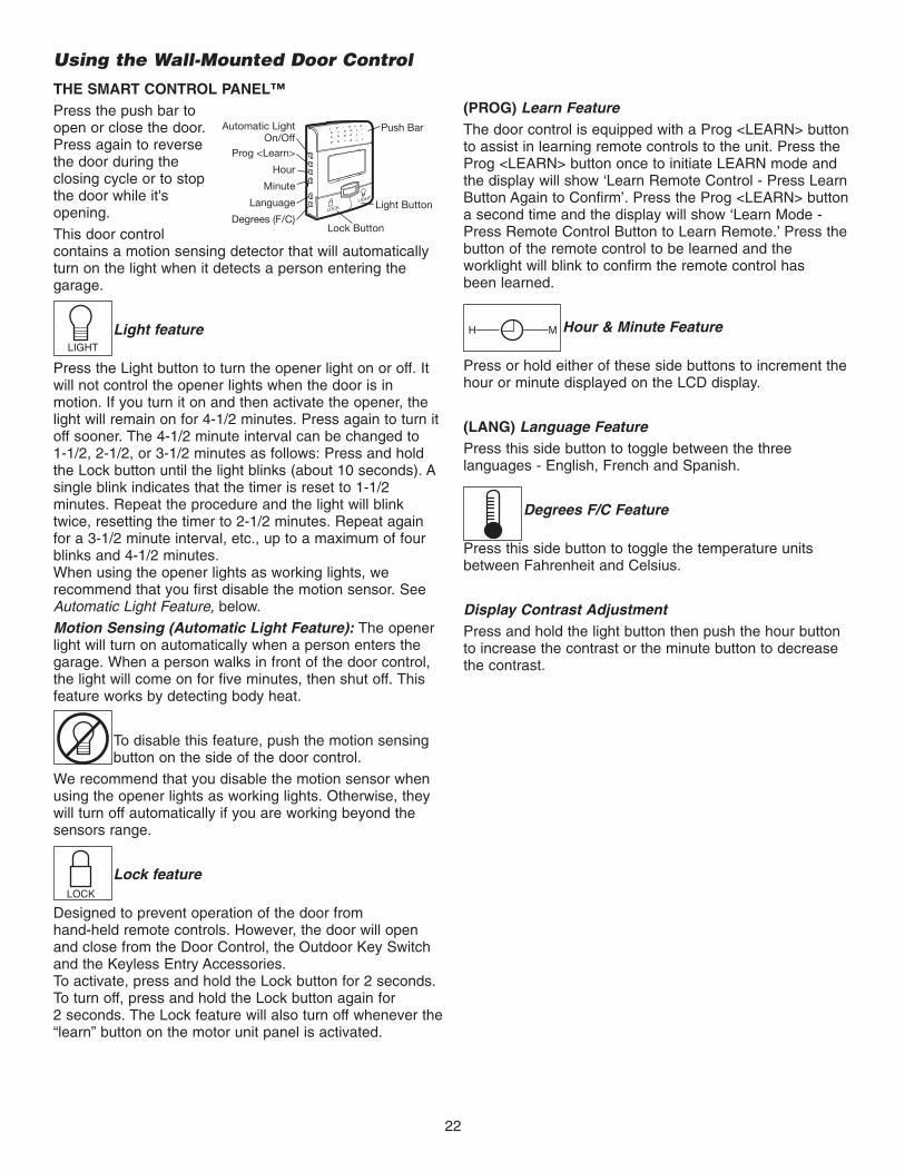
THE SMART CONTROL PANEL™Press the push bar toopen or close the door.Press again to reversethe door during theclosing cycle or to stopthe door while it'sopening.
This door controlcontains a motion sensing detector that will automaticallyturn on the light when it detects a person entering thegarage.
Light feature
Press the Light button to turn the opener light on or off. Itwill not control the opener lights when the door is inmotion. If you turn it on and then activate the opener, thelight will remain on for 4-1/2 minutes. Press again to turn itoff sooner. The 4-1/2 minute interval can be changed to 1-1/2, 2-1/2, or 3-1/2 minutes as follows: Press and holdthe Lock button until the light blinks (about 10 seconds). Asingle blink indicates that the timer is reset to 1-1/2minutes. Repeat the procedure and the light will blinktwice, resetting the timer to 2-1/2 minutes. Repeat againfor a 3-1/2 minute interval, etc., up to a maximum of fourblinks and 4-1/2 minutes.When using the opener lights as working lights, werecommend that you first disable the motion sensor. SeeAutomatic Light Feature, below.
Motion Sensing (Automatic Light Feature): The openerlight will turn on automatically when a person enters thegarage. When a person walks in front of the door control,the light will come on for five minutes, then shut off. Thisfeature works by detecting body heat.
To disable this feature, push the motion sensingbutton on the side of the door control.
We recommend that you disable the motion sensor whenusing the opener lights as working lights. Otherwise, theywill turn off automatically if you are working beyond thesensors range.
Lock feature
Designed to prevent operation of the door from hand-held remote controls. However, the door will openand close from the Door Control, the Outdoor Key Switchand the Keyless Entry Accessories.To activate, press and hold the Lock button for 2 seconds.To turn off, press and hold the Lock button again for2 seconds. The Lock feature will also turn off whenever the“learn” button on the motor unit panel is activated.
Automatic LightOn/Off
Prog <Learn>
Hour
Minute
Language
Degrees (F/C)Lock Button
Light Button
Push Bar
LIGHT
LOCK
(PROG) Learn FeatureThe door control is equipped with a Prog <LEARN> buttonto assist in learning remote controls to the unit. Press theProg <LEARN> button once to initiate LEARN mode andthe display will show ‘Learn Remote Control - Press LearnButton Again to Confirm’. Press the Prog <LEARN> buttona second time and the display will show ‘Learn Mode -Press Remote Control Button to Learn Remote.’ Press thebutton of the remote control to be learned and theworklight will blink to confirm the remote control has been learned.
Hour & Minute Feature
Press or hold either of these side buttons to increment thehour or minute displayed on the LCD display.
(LANG) Language FeaturePress this side button to toggle between the threelanguages - English, French and Spanish.
Degrees F/C Feature
Press this side button to toggle the temperature unitsbetween Fahrenheit and Celsius.
Display Contrast AdjustmentPress and hold the light button then push the hour buttonto increase the contrast or the minute button to decreasethe contrast.
LIGHT
LOCK
H M

23
Using the Remote Control
NOTE: To activate the remote control functions, pull outthe plastic pull tab protruding from the remote controlhousing.
This remote control is equipped with a proximity lightingfeature. When moving a hand within close proximity to theremote control, the LED lights turn on for 3 seconds. Uponsuccessful activation of a remote control button, the LEDlights will blink rapidly.
Proximity Disable FeatureThe remote control will turn off the proximity lightingfeature if the proximity lighting is turned on 10 consecutivetimes without activation of a button. To re-enable theproximity lighting, simply press a button. This functionconserves battery life.
To Control the Opener LightsWith 315MHz Security✚® remote controls, a remote pushbutton can be programmed to operate the opener lightswithout opening the door.
1. With the door closed, press and hold the remote buttonthat you want to control the light.
2. Press and hold the Light button on the multi-functioncontrol panel.
3. Press and hold the Lock button on the multi-functioncontrol panel.
4. After the opener lights flash, release all buttons.
Test by pressing the remote push button. The openerlights should turn on or off but the door should not move.
Troubleshooting
Reduced proximitysensing (does notactivate bytouching top ofremote control)
Check if proximity lighting isdisabled by pressing a button.
Replace 3V2450 battery withsame type 3V2450 coin cell.
The Proximity Sensor may beoversensitized. Sit remote controlundisturbed for 60 seconds on a non-metallic surface. This allowsthe sensor to recalibrate itself.
Dim LED lightsReplace two 3V2016 batterieswith same type 3V2016 coincells.
No rapid LEDblinking afterpressing a button
Replace two 3V2016 batterieswith same type 3V2016 coincells.
PROBLEM SOLUTIONNOTICE: To comply with FCC and or Industry Canada (IC) rules, adjustment or modifications of thisreceiver and/or transmitter are prohibited, except for changing the code setting or replacing thebattery. THERE ARE NO OTHER USER SERVICEABLE PARTS.Tested to Comply with FCC Standards FOR HOME OR OFFICE USE. Operation is subject to thefollowing two conditions: (1) this device may not cause harmful interference, and (2) this devicemust accept any interference received, including interference that may cause undesired operation.
To replace the batteries,remove the two screws andopen the remote controlhousing. Push the battery outof the holder for removal. Insertreplacement batteries positiveside up. Dispose of oldbatteries properly.
Replace the batteries with only3V2016 or 3V2450 coin cellbatteries.
CAUTION: Do not bend spring contact. If bent theproximity sensor will not work.
To prevent possible SERIOUS INJURY or DEATH:• NEVER allow small children near batteries.• If battery is swallowed, immediately notify doctor.
ProximityBattery
LED andOpenerBatteries
SpringContact
To reduce risk of fire, explosion or chemical burn:• Replace ONLY with 3V2016 or 3V2450 coin batteries.• Do NOT recharge, disassemble, heat above 100°C (212°F) or
incinerate.
The Remote Control Battery
The 3V2016 lithium batteries for the opener and LEDlights (marked “LED and Opener Battery”) should last 5years. The 3V2450 lithium battery for the proximity lighting(marked “Proximity Battery”) should last 1-2 years.

24
CARE OF YOUR OPENERMAINTENANCE SCHEDULE
Once a Month• Manually operate door. If it is unbalanced or binding, call
a trained door systems technician.
• Check to be sure door opens & closes fully. Adjust limitsand/or force if necessary (see Adjustment Steps 1 and 2).
• Repeat the safety reverse test. Make any necessaryadjustments (see Adjustment Step 3).
Once a Year• Oil door rollers, bearings and hinges. The opener does
not require additional lubrication. Do not grease the doortracks.
HAVING A PROBLEM?(TROUBLESHOOTING)1. The opener doesn't operate from either the Door
Control or the remote control:• Does the opener have electric power? Plug a lamp into
the outlet. If it doesn't light, check the fuse box or thecircuit breaker. (Some outlets are controlled by a wallswitch.)
• Have you disabled all door locks? Review installationinstruction warnings on page 7.
• Is there a build-up of ice or snow under the door? Thedoor may be frozen to the ground. Remove anyrestriction.
• The garage door spring may be broken. Have itreplaced (see page 3 for reference).
2. Opener operates from the remote, but not from theDoor Control:
• Is the door control lit? If not, reverse the wires. If theopener runs, check for a faulty wire connection at thecontrol console, a short under the staples, or a brokenwire.
• Are the wiring connections correct? Review InstallationStep 5, page 10.
3. The door operates from the Door Control, but notfrom the remote control:
• Is the door push bar flashing? If so, Lock mode isengaged. Make sure it is off by pressing the Lock button for two seconds.
• Program the opener to match the remote control code.(Refer to instructions on the motor unit panel.) Repeatwith all Remote.
4. The remote control has short range:• Change the location of the remote control in your car.
• Check to be sure the antenna on the side or back panelof motor unit extends fully downward.
• Some installations may have shorter range due to ametal door, foil backed insulation, or metalgarage siding.
5. The garage door opens and closes by itself:• Be sure that all remote control push buttons are off.
• Remove the bell wire from the door control terminalsand operate from the remote only. If this solves theproblem, the door control is faulty (replace), or there isan intermittent short on the wire between the controlconsole and the motor unit.
• Clear memory and re-program all remote controls.
6. The door doesn't open completely:• Check power door lock.
• Is something obstructing the door? Is it out of balance,or are the springs broken? Remove the obstruction orrepair the door.
7. The door opens but won't close:• Check cable tension monitor (see installation step 4).
• If the opener lights blink, check the safety reversingsensor. See Installation Step 9.
• If the opener lights don’t blink and it is a newinstallation. See Adjustment Step 2. For an existinginstallation, see below.
Repeat the safety reverse test after the adjustmentis complete.
8. The door reverses for no apparent reason andopener lights don’t blink:
• Check cable tension monitor (see installation step 4).
• Is something obstructing the door? Pull the emergencyrelease handle. Operate the door manually. If it isunbalanced or binding, call a trained door systemstechnician.
• Clear any ice or snow from the garage floor areawhere the door closes.
• Review Adjustment Step 2.
Repeat safety reverse test after adjustments.

25
Having a Problem? (Continued)9. The door reverses for no apparent reason and
opener lights blink for 5 seconds after reversing:• Check the safety reversing sensor. Remove any
obstruction or align the receiving eye. See InstallationStep 9.
10. The opener strains to operate door:• The door may be out of balance or the springs may be
broken. Close the door and use the emergencyrelease handle to disconnect the door. Open and closethe door manually. A properly balanced door will stayin any point of travel while being supported entirely byits springs. If it does not, disconnect the opener andcall a trained door systems technician.
11. The opener motor hums briefly, then won't work:• The garage door springs may be broken. See above.
• If the problem occurs on the first operation of theopener, door may be locked. Disable the power doorlock.
12. The opener won't operate due to power failure:• Manually open the power door lock.
• Use the emergency release handle to disconnect thedoor. The door can be opened and closed manually.When power is restored, pull manual release a secondtime.
• If a Battery Backup Unit is connected, the openershould be able to operate up to 20 times withoutpower.
13. Door loses limits.• Collar not tightened securely. Tighten collar
(see Assembly Steps 1 and 2) and reprogram limits(see Adjustment Step 1).
14. The operator moves when the door is in operation:• Some minor movement is normal for this product. If it
is excessive the collar will wear prematurely.
• Check to make sure the torsion bar is not movingleft/right excessively.
• Check to make sure the torsion bar is not visiblymoving up and down as it rotates.
• Check that the operator is mounted at a right angle tothe jackshaft. If not, move the position of the mountingbracket.
15. Power lock makes noise when operating.• Call Liftmaster® dealer for replacement power lock.

26
Meaning: This message will appear if the Safety Reversing Sensors are out ofalignment, if they are blocked or if the wiring is disconnected. To clear messagefrom Smart Control Panel™ do the following:• Check to see that area is clear between the Safety Reversing Sensors.• Check to see that the Safety Reversing Sensors are not misaligned.
• Realign receiving eye sensor, clean lens and secure brackets.
• Verify door track is firmly secured to wall and does not move.
• Check to see that the Safety Reversing Sensors’ wires are connected to the motor unit.
• If message has not cleared after the above checks, refer to message #2.
Meaning: This message will appear if the Safety Reversing Sensors are miswired.To clear the message, do the following:• Inspect the safety sensor wires for a short (staple in wire), correct wiring polarity
(black/white wires reversed), replace/attach as needed.
• Disconnect all wires from back of motor unit.
• Remove safety sensors from brackets and shorten sensor wires to 1-2 ft. (30-60 cm)from back of each sensor.
• Reattach sending eye to motor unit using shortened wires. If sending eye indicator lightglows steadily, attach the receiving eye.
• Align sensors, if the indicator lights glow replace the wires for the sensors. If the sensorindicator lights do not light, replace the safety sensors.
Meaning: This message will appear when the Prog <LEARN> button has beenpressed on the Smart Control Panel™. Pressing the Prog <LEARN> button again willallow the user to program an additional remote control to the opener.
Meaning: This message will appear when the Prog <learn> button has been presseda second time on the Smart Control Panel™ or anytime on the opener. The opener isready to program another remote control by simply pressing the remote controlbutton. Once the opener has ‘LEARNED’ the remote control, the worklight will blinkone time.
Meaning: This message will appear when the ‘Lock’ button has been pressed andheld for more than one second. This feature will disable the opener from receivingremote control signals. To exit ‘LOCK’ mode, press and hold the button for morethan one second.
Meaning: This message will appear when the ‘Language’ button has been pressed.Pressing the button will toggle to the next language.
Meaning: This message will appear when the ‘MOTION SENSING’ button is pressed.The Motion Detector will toggle on or off with each press of the button.
LEARN REMOTECONTROL. PRESSLEARN BUTTON TOCONFIRM.
LEARN MODE.PRESS REMOTECONTROL BUTTONTO PROGRAMREMOTE.
LOCK MODE.REMOTE CONTROLLOCKED OUT.PRESS LOCKBUTTON TO ENABLEREMOTE.
SAFETY SENSORSMALFUNCTION.CHECK MISWIRING.SEE OWNER’SMANUAL.
Message
Message
Message
Message
Message
ENGLISH, FRANÇAISAND ESPAÑOL.
Message
MOTION SENSINGON, MOTIONSENSING OFF.
Message
Smart Control Panel™ Messages
The following messages are contained within the Smart Control Panel™ and may appear during the operations of the unit:
SAFETY SENSORSCHECK ALIGNMENT,BLOCKAGE ORMISWIRING. SEEOWNER’S MANUAL.

27
Your garage door opener is programmed with self-diagnosticcapabilities. The “Learn” button/diagnostic LED will flash anumber of times then pause signifying it has found apotential issue. Consult Diagnostic Chart below.
Diagnostic Chart
Symptom: One or both of the Indicator lights on the safety reversing sensorsdo not glow steady.• Inspect sensor wires for a short (staple in wire), correct wiring polarity (black/white
wires reversed), broken or disconnected wires, replace/attach as needed.• Disconnect all wires from back of motor unit.• Remove sensors from brackets and shorten sensor wires to 1-2 ft (30-60 cm) from
back each of sensor.• Reattach sending eye to motor unit using shortened wires. If sending eye indicator
light glows steadily, attach the receiving eye. • Align sensors, if the indicator lights glow replace the wires for the sensors. If the
sensor indicator lights do not light, replace the safety reversing sensors.
Symptom: LED is not lit on door control.• Inspect door control/wires for a short (staple in wire), replace as needed.• Disconnect wires at door control, touch wires together. If motor unit activates,
replace door control.• If motor unit does not activate, disconnect door control wires from motor unit.
Momentarily short across red and white terminals with jumper wire. If motor unitactivates, replace door control wires.
Symptom: Sending indicator light glows steadily, receiving indicator light isdim or flashing.• Realign receiving eye sensor, clean lens and secure brackets. • Verify door track is firmly secured to wall and does not move.
Symptom: Motor has overheated; the motor unit does not operate = Motor unithums briefly; RPM Sensor = Short travel 6-8" (15-20 cm).• Unplug unit to reset. Try to operate motor unit, check diagnostic code.• If it is still flashing 5 times and motor unit moves 6-8" (15-20 cm), replace RPM
sensor. • If motor unit doesn’t operate, motor unit is overheated. Wait 30 minutes and retry. If
motor unit still will not operate replace logic board.
Symptom: Door reverses while closing.• Check for possible door obstructions and remove.• Check that the cable tension monitor is properly connected to the operator.• Replace the cable tension monitor.
Cable tension monitorreversal.
Motor overheated orpossible RPM sensorfailure. Unplug to reset.
Safety reversing sensorsslightly misaligned (dim or flashing LED).
Door control orwire shorted.
Safety reversing sensorswire shorted orblack/white wire reversed.
Safety reversing sensorswire open (broken ordisconnected).
1 FLASH
2 FLASHES
3 FLASHES
4 FLASHES
5 FLASHES
9 FLASHES
OR
“Learn” Button LED or DiagnosticLED
“Learn” Button
Installed Safety Reversing
Sensor

28
*3-Button RemoteIf provided with your garage door opener, the large button isfactory programmed to operate it. Additional buttons on anySecurity✚®
3-Button remote ormini-remote can beprogrammed tooperate otherSecurity✚® garagedoor openers.
To Erase All Codes FromMotor Unit Memory
To deactivate any unwanted remote, firsterase all codes:
Press and hold the “learn” button onmotor unit until the learn indicator lightgoes out (approximately 6-9 seconds).All previous codes are now erased.Reprogram each remote or keylessentry you wish to use.
Your garage door opener has already been programmed at the factory to operate with your hand-held remote control. The doorwill open and close when you press the large push button.
Below are instructions for programming your opener to operate with additional Security✚® remote controls.
1. Press and release the purple “learn”button on the motor unit. The learnindicator light will glow steadily for 30seconds.
2. Within 30 seconds, press and hold thebutton on the hand-held remote* thatyou wish to operate your garage door.
3. Release the button when the motorunit lights blink. It has learned thecode. If light bulbs are not installed,two clicks will be heard.
To Add or Reprogram a Hand-held Remote ControlUSING THE “LEARN” BUTTON USING THE SMART CONTROL PANEL™
LOCKLIGHT
PROGRAMMINGNOTICE: If this Security✚® garage door opener is operated with a non-rolling code transmitter, the technical measure in thereceiver of the garage door opener, which provides security against code-theft devices, will be circumvented. The owner of thecopyright in the garage door opener does not authorize the purchaser or supplier of the non-rolling code transmitter tocircumvent that technical measure.
LOCK
LIGHT
LOCKLIGHT
LOCK
LIGHT
1. Press the Prog <Learn> button on theSmart Control Panel™.
2. Press the Prog <Learn> button againto confirm Learn Mode.
3. Press the button on the hand-heldremote that you wish to operate yourgarage door.
4. When the motor unit lights blink, it haslearned the code. If light bulbs are notinstalled, two clicks will be heard.
LOCK
LIGHT
LOCK
LIGHT

29
1. Press and release the purple “learn”button on motor unit. The learnindicator light will glow steadily for 30seconds.
2. Within 30 seconds, enter a four digitpersonal identification number (PIN)of your choice on the keypad. Thenpress and hold the ENTER button.
3. Release the button when the motorunit lights blink. It has learned thecode. If light bulbs are not installed,two clicks will be heard.
To Add, Reprogram or Change a Keyless Entry PINNOTE: Your new Keyless Entry must be programmed to operate your garage door opener.
USING THE “LEARN” BUTTON USING THE SMART CONTROL PANEL™
LOCKLIGHT
To change an existing, known PINIf the existing PIN is known, it may be changed by oneperson without using a ladder.
1. Press the four buttons for the present PIN, then press andhold the # button.
The opener light will blink twice. Release the # button.
2. Press the new 4-digit PIN you have chosen, thenpress Enter.
The motor unit lights will blink once when the PIN has beenlearned.
Test by pressing the new PIN, then press Enter. The doorshould move.
To set a temporary PINYou may authorize access by visitors or service people with atemporary 4-digit PIN. After a programmed number of hoursor number of accesses, this temporary PIN expires and willno longer open the door. It can be used to close the dooreven after it has expired. To set a temporary PIN:
1. Press the four buttons for your personal entry PIN (not thelast temporary PIN), then press and hold the ✽ button.
The opener light will blink three times. Release the button.
2. Press the temporary 4-digit PIN you have chosen, thenpress Enter.
The opener light will blink four times.
3. To set the number of hours this temporary PIN will work,press the number of hours (up to 255), then press ✽.
OR3. To set the number of times this temporary PIN will open
door, press the number of times (up to 255), then press #.
The opener light will blink once when the temporary PIN hasbeen learned.
Test by pressing the four buttons for the temporary PIN, thenpress Enter. The door should move. If the temporary PIN wasset to a certain number of openings, remember that the testhas used up one opening.To clear the temporary password,repeat steps 1-3, setting the number of hours or times to 0 instep 3.
One Button Close: Opener can be closed by pressing onlythe ENTER button if the one button close feature has beenactivated. This feature has been activated at the factory. Toactivate or deactivate this feature press and hold buttons 1and 9 for 10 seconds. The keypad will blink twice when theone button close is active. The keypad will blink four timeswhen one button close is deactivated.
LOCK
LIGHT
1. Press the Prog <Learn> button on theSmart Control Panel™.
2. Press the Prog <Learn> button againto confirm Learn Mode.
3. Enter a four digit personalidentification number (PIN) of yourchoice on the keypad. Then pressenter.
4. When the motor unit lights blink, ithas learned the code. If light bulbsare not installed, two clicks will beheard.
NOTE: This method requires two people if the KeylessEntry is already mounted outside the garage.
LOCK
LIGHT
LOCK
LIGHT

30
1. Press the “learn button” on light untilLED comes ON.
2. Activate the garage door using thehand-held remote, wall control orkeyless entry.
3. It has learned the code and the lightturns on.
Reprogramming Light or Additional LightYour garage door opener remote light has already been programmed at the factory to operate with your opener. Anyadditional or replacement remote lights will need to be programmed.

31
12
NOTICE
1
13 14
15
LOCK
LIGHT
3
4 2
5
6
7
8
9
1011
Installation Parts
REPAIR PARTS
KEY PARTNO. NO. DESCRIPTION1 398LM Smart Control Panel™2 373P 3-Button remote control3 10A19 3V2016 lithium battery: led and opener4 10A33 3V2450 lithium battery: proximity switch5 29C151 Remote control visor clip6 41A4582 Emergency release rope & handle
assembly7 41B4494-1 2-Conductor bell wire - white & white/red8 41A6104 Cable tension monitor9 41C0902 Mounting bracket10 41A5034 Safety sensor kit (receiving and
sending eyes) with 3' (.9 m)2-conductor bell wire attached
KEY PARTNO. NO. DESCRIPTION
11 41A6388 Collar with set screws (2)12 41A6102 Power door lock13 41A5266-1 Safety sensor brackets (2)14 380LM Remote Light (Opener Light)15 41D96-1 Light lens for light
NOT SHOWN101D173 Push bar for door control41A6288 Hardware bag for light41A6298 Installation hardware bag
(includes hardware listed on page 5)114A3399 Owner’s manual114A3399SP Owner’s manual - Spanish

32
3
2
6
5
4
1
KEY PARTNO. NO. DESCRIPTION
1 41DJ001 Logic board complete with plate
2 41A6408 Absolute Encoder System
3 41C168 Transformer
KEY PARTNO. NO. DESCRIPTION
4 41A6095 Motor with bracket
5 41B122 Power cord
6 41A6348-3 Cover
Motor Unit Assembly Parts

33
LOCKLIGHT
CLOSED
OPEN
ACCESSORIES
370LM
41A5281
377LM
Extension Brackets:(Optional) For safety reversingsensor installation onto the wallor floor.
Keyless Entry with Security✚®:Enables homeowner to operategarage door opener from outsideby entering a password on aspecially designed keyboard. Alsocan add a temporary password forvisitors or service persons. Thistemporary password can be limitedto a programmable number ofhours or entries.
3-Button Mini-Remote Controlwith Security✚®:With key ring.
902LM/903LM 2 & 3 Door Multi-Function WallControl:Ideal for homes with up to threegarage doors. Combine up tothree controls into one wall controlpanel for a neat compactappearance. Enhanced functionsinclude Lock Feature to lock outoutside radio signals while you areaway from home and turn openerlights on or off from the control panel.
Garage Door Monitor:Security for the largest door of yourhome!
Tells you if your garage door is open orclosed. Monitors up to 4 garage doorsby adding additional sensor modules.
915LM
Garage Door Monitor Sensor:Additional accessory sensor for homeswith multiple garage doors.
916LM
EverCharge™ Battery BackupSystem:Provides backup power to the model3800 and 3500 garage door openers.
475LM
373LM 3-Button Security✚® Remote Control:
Includes visor clip.
Wireless Door Control:Push bar, light feature and auxiliarybutton. Includes battery.
378LM
373W Designer Burled Walnut 3-ButtonRemote Control with Security✚®:Includes visor clip.
395LM Remote Light Control:Enables homeowner to turn on alamp, television or other appliancefrom their car with their garagedoor opener remote or fromanywhere in their home with anadditional LiftMaster Security✚®
remote.
380LM Remote Light:Enables homeowner to turn on awork light from their car with theirgarage door opener remote orfrom anywhere in their home withan additional LiftMaster Security✚®
remote.
975LM Laser Park Assist:Laser enables homeowners toprecisely park vehicles in thegarage.
373P 3-Button Security✚® Remote Control:
Includes visor clip.
480LM Alternate Mounting Kit:
This kit allows model 3800 to bemounted below the torsion bar in thecase where the torsion bar is not round or the normal mounting area is obstructed.

34
OPERATOR NOTES

35
OPERATOR NOTES

LIFTMASTER® SERVICE ISON CALL
OUR LARGE SERVICE ORGANIZATIONSPANS AMERICA
INSTALLATION AND SERVICE INFORMATION IS AS NEARAS YOUR TELEPHONE.
SIMPLY DIAL OUR TOLL FREE NUMBER:
1-800-528-9131
www.liftmaster.com
For professional installation, parts and service, contactyour local LIFTMASTER/CHAMBERLAIN dealer. Look for himin the Yellow Pages, or call our Service number for a list ofdealers in your area.
HOW TO ORDERREPAIR PARTS
Selling prices will be furnished on request or parts will beshipped at prevailing prices and you will be billed accordingly.
WHEN ORDERING REPAIR PARTS, ALWAYS GIVE THEFOLLOWING INFORMATION:
• PART NUMBER
• PART NAME
• MODEL NUMBER
ADDRESS ORDERS TO:THE CHAMBERLAIN GROUP, INC.
Technical Support Group6020 S. Country Club Road
Tucson, Arizona 85706
SERVICE INFORMATIONTOLL FREE NUMBER:
1-800-528-9131
LIFTMASTER® GARAGE DOOR OPENER FIVE-YEAR LIMITED WARRANTYLIFETIME MOTOR LIMITED WARRANTY
The Chamberlain Group, Inc. (“Seller”) warrants to the first retail purchaser of this product, for the residence in which this product is originally installed, that it is freefrom defect in materials and/or workmanship for a period of five years from the date of purchase [and that the motor is free from defect in materials and/or workmanshipfor a period of lifetime from the date of purchase]. The proper operation of this product is dependent on your compliance with the instructions regarding installation,operation, maintenance and testing. Failure to comply strictly with those instructions will void this limited warranty in its entirety.
If, during the limited warranty period, this product appears to contain a defect covered by this limited warranty, call 1-800-528-9131, toll free, before dismantling thisproduct. Then send this product, pre-paid and insured, to our service center for warranty repair. You will be advised of shipping instructions when you call. Pleaseinclude a brief description of the problem and a dated proof-of-purchase receipt with any product returned for warranty repair. Products returned to Seller for warrantyrepair, which upon receipt by Seller are confirmed to be defective and covered by this limited warranty, will be repaired or replaced (at Seller's sole option) at no costto you and returned pre-paid. Defective parts will be repaired or replaced with new or factory-rebuilt parts at Seller's sole option.
ALL IMPLIED WARRANTIES FOR THE PRODUCT, INCLUDING BUT NOT LIMITED TO ANY IMPLIED WARRANTIES OF MERCHANTABILITY AND FITNESSFOR A PARTICULAR PURPOSE, ARE LIMITED IN DURATION TO THE FIVE YEAR LIMITED WARRANTY PERIOD SET FORTH ABOVE [EXCEPT THE IMPLIEDWARRANTIES WITH RESPECT TO THE MOTOR, WHICH IS LIMITED IN DURATION TO THE LIFETIME LIMITED WARRANTY PERIOD FOR THE MOTOR], ANDNO IMPLIED WARRANTIES WILL EXIST OR APPLY AFTER SUCH PERIOD. Some States do not allow limitations on how long an implied warranty lasts, sothe above limitation may not apply to you. THIS LIMITED WARRANTY DOES NOT COVER NON-DEFECT DAMAGE, DAMAGE CAUSED BY IMPROPERINSTALLATION, OPERATION OR CARE (INCLUDING, BUT NOT LIMITED TO ABUSE, MISUSE, FAILURE TO PROVIDE REASONABLE AND NECESSARYMAINTENANCE, UNAUTHORIZED REPAIRS OR ANY ALTERATIONS TO THIS PRODUCT), LABOR CHARGES FOR REINSTALLING A REPAIRED ORREPLACED UNIT, REPLACEMENT OF BATTERIES AND LIGHT BULBS OR UNITS INSTALLED FOR NON-RESIDENTIAL USE.
THIS LIMITED WARRANTY DOES NOT COVER ANY PROBLEMS WITH, OR RELATING TO, THE GARAGE DOOR OR GARAGE DOOR HARDWARE,INCLUDING BUT NOT LIMITED TO THE DOOR SPRINGS, DOOR ROLLERS, DOOR ALIGNMENT OR HINGES. THIS LIMITED WARRANTY ALSO DOES NOTCOVER ANY PROBLEMS CAUSED BY INTERFERENCE. ANY SERVICE CALL THAT DETERMINES THE PROBLEM HAS BEEN CAUSED BY ANY OF THESEITEMS COULD RESULT IN A FEE TO YOU.
UNDER NO CIRCUMSTANCES SHALL SELLER BE LIABLE FOR CONSEQUENTIAL, INCIDENTAL OR SPECIAL DAMAGES ARISING IN CONNECTION WITHUSE, OR INABILITY TO USE, THIS PRODUCT. IN NO EVENT SHALL SELLER'S LIABILITY FOR BREACH OF WARRANTY, BREACH OF CONTRACT,NEGLIGENCE OR STRICT LIABILITY EXCEED THE COST OF THE PRODUCT COVERED HEREBY. NO PERSON IS AUTHORIZED TO ASSUME FOR US ANYOTHER LIABILITY IN CONNECTION WITH THE SALE OF THIS PRODUCT.
Some states do not allow the exclusion or limitation of consequential, incidental or special damages, so the above limitation or exclusion may not apply to you. Thislimited warranty gives you specific legal rights, and you may also have other rights which vary from state to state.
© 2007, The Chamberlain Group, Inc.114A3399B All Rights Reserved