gapfiller
52
EQUIPMENT AND SYSTEMS FOR DIGITAL TV BROADCASTING
description
gapfiller
Transcript of gapfiller

EQUIPMENT AND SYSTEMS FORDIGITAL TV BROADCASTING
TRedess 2010, S.L.Volta do Castro, s/n15706 Santiago de CompostelaS P A I N
GPS N: 42° 51’ 52.93”, W: 8° 34’ 5.19”T +34 981 534 203F +34 981 522 [email protected]
TRedess is certifi ed byUNE - EN ISO 9001:2008
06010002 v0514 – Specifi cations are subject to change without notice.


TRedess is a leading company in professional telecommunications solutions. We are specialized in the design, development and manufacturing of competitive, reliable and innovative solutions for the extension of coverage for digital and analog television broadcasting networks.
Our main products are Low Power Transmitters, Gap Fillers and Regenerative Transposers for Digital Terrestrial Television Networks (DVB-T/T2), to make the TV signal available where the primary TV network infrastructure cannot reach. With a solid and constant investment in R&D, we are able to develop competitive, reliable and innovative solutions responding to markets in technological evolution.
Our aim is to provide complete and integral solutions to our customers, combining our high-quality equipment, control and monitoring systems and all the necessary accessories for a complete solution.
ABOUT US

02 I TREDESS
EQUIPMENT FOR TV BROADCASTING
The TRedess transmitters and gap fillers are developed to optimize the coverage areas extension for digital TV networks in a reliable and cost-competitive way.
We divide our digital TV portfolio into two product series, Compact Series and Broadcast Series. Both series are DVB-T/T2 compliant, and include remote control and monitoring, power supply redundancy, as well as two channel redundancy options, N+1 and 1+1.
Compact Series is a highly compact solution offering nominal output powers up to 10W. Broadcast Series equipment offers a higher range of output powers up to 150W.
TRedess systems allow both local and remote management and alarm control. The equipment is locally configurable using an external programmer. Besides, it can be controlled and monitored with the TRedess Remote Management system over different interfaces and protocols.
TRedess equipment can also be managed with the TRedess Web Server Management application tool.
TRedess gap fillers can optionally incorporate a very high-performance Echo Canceller, making TRedess gap fillers ideal for operation in single-frequency networks with limited isolation between the receiving and transmitting antennas.
There are two echo cancelling solutions available: DAE (Digital Adaptive Equalizer) and DEEC (Doppler Enhanced Echo Canceller).
DAE echo canceller is usedunder moderate echo conditions,supporting -10 dB gain marginlevel. Furthermore, DAE is ableto cancel multipath propagationeffects in the receiving signalby correcting (equalizing) thedistortions in amplitude of the inputsignal spectrum of the gap fillercaused by very close echoes.
The Doppler Enhanced EchoCanceller (DEEC) is able to cancelechoes with greater gain margin(echo levels 24dB higher than theinput signal) and can even suppressDoppler effect.
EQUIPMENT FOR TV BROADCASTING
T V BROADC ASTING I 03
INDEX
05 EQUIPMENT FOR DIGITAL TERRESTRIAL TELEVISION
A Compact Series 06 DVB-T/T2 1W, 5W & 10W Transmitters, Gap Fillers, Regenerative Transposers 13 Remote Management 14 Synchronization 15 Redundancy 16 DVB-S2/ASI Converter 17 IP/ASI Converter 18 Compact Series References List 19 Compact Series Ordering Information
B Broadcast Series 20 DVB-T/T2 5W, 10W, 20W, 50W and 100W Transmitters, Gap Fillers 28 Remote Management 30 Synchronization 31 Redundancy
C Echo Cancelling 32 DAE (Digital Adaptive Equalizer) 32 DEEC (Doppler Enhanced Echo Canceller)
D Remote Control & Monitoring 34 Remote Control & Monitoring 36 Remote Monitoring System for DVBT/T2
39 INTEGRATED SOLUTIONS
E Accessories for Broadcasting 42 COFDM-ASI Converter 42 Active Demultiplexer 42 Multiplexer Filters 43 Transmission Panels 43 Power Distributors 43 Reception Antennas
Cabinets 44 Indoor Cabinets 46 Outdoor Cabinets

T V BROADC ASTING I 05
EQUIPMENTFOR DIGITALTERRESTRIALTELEVISION

COM
PAC
T SE
RIE
S
A
06 I TREDESS
EQUIPMENT FOR DIGITAL TERRESTRIAL TV COMPACT SERIES
Technical description
Compact Series is the new generation of TRedess transmitters and gap fillers, developed to optimize coverage areas for digital TV networks in an economic and reliable way.
Compact series equipment is a highly compact solution: up to 7 transmitters, gap fillers or regenerative transposers can be hosted in a 19”x 5HU subrack, delivering an output power of up to 10W.
Main Characteristics
• High Integration Level: Up to 7 channels in a 5U subrack.• Up to 10W Transmitters, Gap Fillers and Regenerative Transposers.• DVB-T/T2 compliant.• Two very high-performance echo cancellation options.• SFN and MFN configurations.• SFN synchronization system (GPS)• Redundancy system N+1, 1+1.• Optional power supply redundancy.• Remote control & monitoring system.• Hot-Swap Modules.• Frequency agility.• Very low power consumption.• Very low phase noise local oscillators.• LDMOS amplifiers.• Independent operating mode.• Electromagnetic compatibility and safety according to the CE regulation norms.
COMPACT SERIES TRANSMITTERS, GAP FILLERS & REGENERATIVE TRANSPOSERS
CO
MPA
CT
SER
IES
A
T V BROADC ASTING I 07
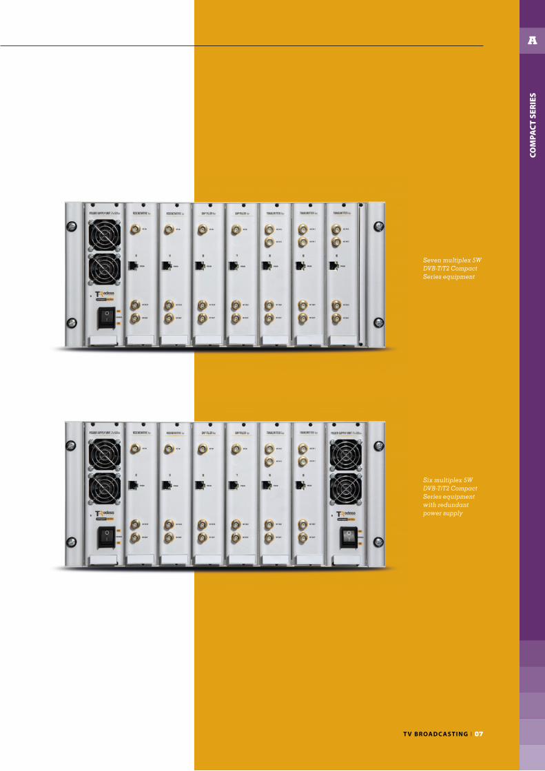
Seven multiplex 5W DVB-T/T2 Compact Series equipment
Six multiplex 5W DVB-T/T2 Compact Series equipment with redundant power supply
COM
PAC
T SE
RIE
S
A
08 I TREDESS
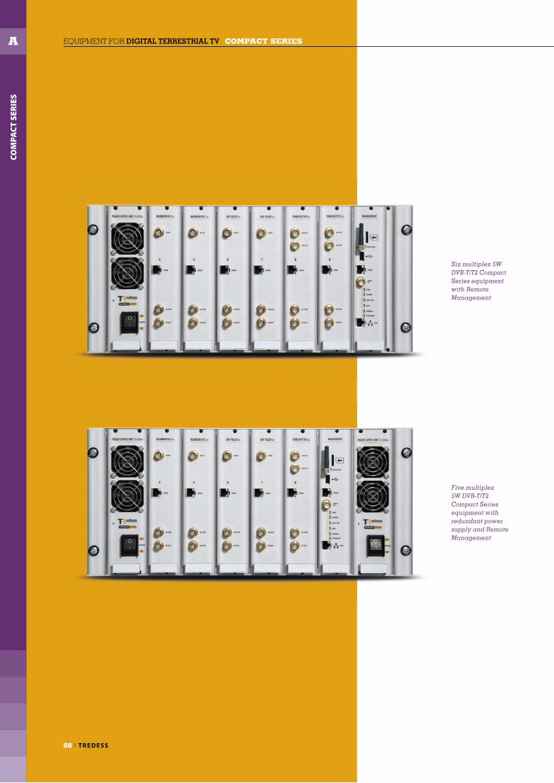
Six multiplex 5W DVB-T/T2 Compact Series equipment with Remote Management
Five multiplex 5W DVB-T/T2 Compact Series equipment with redundant power supply and Remote Management
EQUIPMENT FOR DIGITAL TERRESTRIAL TV COMPACT SERIES

COM
PAC
T SE
RIE
S
A
T V BROADC ASTING I 09
TRedess DVB-T TRANSMITTERS 1W, 5W, 10W I COMPACT SERIES I Technical specifications
Denomination MOD ASI-RF DVB-T 1W CS MOD ASI-RF DVB-T 5W CS MOD ASI-RF DVB-T 10W CS
Technical specifications
DVB-T Modulator. Modes
FFT 2K, 8K
Guard interval 1/4, 1/8, 1/16, 1/32
FEC 1/2, 2/3, 3/4, 5/6, 7/8
Constellation QPSK, 16 QAM, 64 QAM
Network MFN & SFN
Bandwidth 6, 7, 8 MHz
MFN adaptation rate Yes. Jitter PCR Restamping ±40ns
DVB-T Modulator. Inputs
MPEG2 / MPEG4 2 ASI seamless (redundant)
MPEG input impedance 75 Ω
MPEG input connector BNC Female
10MHz (SFN) synchronization input
Input level -20 dBm to +10 dBm
Impedance 50 Ω
Connector BNC female (back of module)
1 pps synchronization input
Level 0 - 5 V
Trigger Selected by rise-edge or fall-edge
Connector BNC female (back of module)
Local oscillators
Phase noise > 95 dBc/Hz @ 1KHz (MFN mode). Negligible in SFN mode.
Frequency stability with temperature (-10 to 60ºC) (without external GPS input)
± 1 x 10e-6
Frequency stability for a year (without external GPS input)
± 1 x 10e-6
RF output
Frequency range 1 UHF 6, 7 or 8 MHz channel
Maximum output power [W] 1,26W 7W 14W
Maximum output power [dBm] 31 dBm 38,5 dBm 41,5 dBm
Distance to the shoulders >38 dB
MER >34 dB
Power stability < ± 0,5 dB
Return losses >20 dB
Spurious emissions out of channel (without Filter)
<-60 dBc
Impedance 50 Ω
Connector BNC Female N Female
RF test output
Coupling 27 ± 3 dB 38 ± 3 dB 38 ± 3 dB
Impedance 50 Ω
Connector BNC Female
General
Control and monitoring interfaces & protocols Ethernet, Relays · IP, HTTP, FTP, GSM/GPRS, UMTS/HSDPA, SNMP
Input voltage range 220 Vac ± 15%
DC Power Consumption * 23W 65W 85W
Operating temperature range 0 to 45ºC
Relative humidity < 95% @ 40ºC, non condensing
Power factor (Power supply) 0,99
Dimensions [width x height x depth] Up to 7 (1W and 5W) or up to 5 (10W) transmitters in 19” x 5HU x 250mm
Cooling Active (forced ventilation)
Directives & standards
R&TTE1999/5/EC, EN 301489-1, EN 301489-14, EN 60950, EN 60215:1989+A1:92+A2:94, EN 61000-3-2: 2006 + A1 + A2, EN 61000-3-3: 2008,
EN 302296-2, 1999/519/EC
RoHS 2011/65/EU
Standards EN 300744, EN 302304, TS 101191, EN 50083-9, TR 101290, TS 102 773, TS 102 831
* DC Power Consumption is specified at the Maximum Output Power transmitted for every power range.

EQUIPMENT FOR DIGITAL TERRESTRIAL TV COMPACT SERIES
COM
PAC
T SE
RIE
S
A
10 I TREDESS
TRedess DVB-T/T2 TRANSMITTERS 1W, 5W, 10W I COMPACT SERIES I Technical specifications
Denomination MOD ASI-RF DVB-T2 1W CS MOD ASI-RF DVB-T2 5W CS MOD ASI-RF DVB-T2 10W CS
Technical specifications
DVB-T Modulator. Modes
FFT 2K, 8K
Guard interval 1/4, 1/8, 1/16, 1/32
FEC 1/2, 2/3, 3/4, 5/6, 7/8
Constellation QPSK, 16 QAM, 64 QAM
Network MFN & SFN
Bandwidth 6, 7, 8 MHz
MFN adaptation rate Yes. Jitter PCR Restamping ±40ns
DVB-T2 Modulator. Modes
FFT 1K, 2K, 4K, 8K, 16K, 32K (normal or extended)
Guard interval 1/4, 19/256, 1/8, 19/128, 1/16, 1/32, 1/128
FEC 1/2, 3/5, 2/3, 3/4, 4/5, 5/6
Constellation QPSK, 16 QAM, 64 QAM, 256 QAM (normal or rotated)
Network MFN & SFN
Bandwidth 1.7, 5, 6, 7, 8 MHz
MFN adaptation rate Yes. Jitter PCR Restamping ±40ns
Input modes TS(SPLP) over ASI · T2MI (SPLP & MPLP*) over ASI
PLPs Up to 8 PLPs
Pilot patterns PP1 … PP8
Efficiency mode Normal & High
Operation mode SISO and/or MISO
DVB-T/T2 Modulator. Inputs
MPEG2 / MPEG4 2 ASI seamless (DVB-T mode). 2 ASI redundant (DVB-T2 mode).
MPEG input impedance 75 Ω
MPEG input connector BNC Female
10MHz (SFN) synchronization input
Input level -20 dBm to +10 dBm
Impedance 50 Ω
Connector BNC female (back of module)
1 pps synchronization input
Level 0 - 5 V
Trigger Selected by rise-edge or fall-edge
Connector BNC female (back of module)
Local oscillators
Phase noise > 95 dBc/Hz @ 1KHz (MFN mode). Negligible in SFN mode.
Frequency stability with temperature (-10 to 60ºC) (without external GPS input)
± 1 x 10e-6
Frequency stability for a year (without external GPS input)
± 1 x 10e-6
RF output
Frequency range 1 UHF 6, 7 or 8 MHz channel
Maximum Output Power [W] 1,58W 7,9W 14W
Maximum Output Power [dBm] 32 dBm 39 dBm 41,5 dBm
Distance to the shoulders >38 dB
MER >35 dB
Precorrection Digital
Power stability < ± 0,5 dB
Return losses >20 dB
Spurious emissions out of channel (without Filter)
<-60 dBc
Impedance 50 Ω
Connector BNC Female N Female
RF test output
Coupling 27 ± 3 dB 38 ± 3 dB 38 ± 3 dB
Impedance 50 Ω
Connector BNC Female
General
Control and monitoring interfaces & protocols Ethernet, Relays · IP, HTTP, FTP, GSM/GPRS, UMTS/HSDPA, SNMP
Input voltage range 220 Vac ± 15%
DC Power Consumption * 26W 68W 88W
Operating temperature range 0 to 45ºC
Relative humidity < 95% @ 40ºC, non condensing
Power factor 0,99
Dimensions [width x height x depth] Up to 7 (1W and 5W) or up to 5 (10W) transmitters in 19” x 5HU x 250mm
Cooling Active (forced ventilation)
Directives & standards
R&TTE1999/5/EC, EN 301489-1, EN 301489-14, EN 60950, EN 60215:1989+A1:92+A2:94, EN 61000-3-2: 2006 + A1 + A2, EN 61000-3-3: 2008,
EN 302296-2, 1999/519/EC
RoHS 2011/65/EU
Standards EN 300744, EN 302304, EN 302775, TS 101191, EN 50083-9, TR 101290, TS 102 773, TS 102 831
* DC Power Consumption is specified at the Maximum Output Power transmitted for every power range. Values correspond to DVB-T2 mode; consumption in DVB-T mode is 3W less for every power range.

COM
PAC
T SE
RIE
S
A
T V BROADC ASTING I 11
TRedess DVB-T/T2 GAP-FILLERS 1W, 5W, 10W I COMPACT SERIES I Technical specifications
Denomination MOD RF-RF 1W CS MOD RF-RF 5W CS MOD RF-RF 10W CS
Technical specifications
RF input
Frequency range 1 UHF 8 MHz channel
Input signal range -70 to -20 dBm
Noise figure ≤ 8 dB
Return losses ≥ 15 dB
Image frequency rejection ≥ 65 dB
Adjacent channel rejection ≥ 80 dB
Impedance 50 Ω
Connector BNC Female
DAE (Digital Adaptive Equalizer)
Gain Margin (signal - echo) -10 dB
Cancelation window 0 - 8 µs
Output power adaptive regulation Yes
DEEC (Doppler Enhanced Echo Canceller)
Gain Margin (signal - echo) -24 dB
Cancellation window 3 configurable cancellation windows. Selective cancellation up to 37,6 µs.
Doppler cancellation Yes
External synchronization input
Frequency 10 MHz
Input level range -20 to +10 dBm
Connector BNC Female
Local oscillators
Phase noise > 95 dBc/Hz @ 1KHz (MFN mode). Negligible in SFN mode.
Frequency stability with temperature (-10 to 60ºC) (without external GPS input)
± 1 x 10e-6
Frequency stability for a year (without external GPS input)
± 1 x 10e-6
RF output
Frequency range 1 UHF 8 MHz channel
Maximum output power [W] 1,26W 7W 14W
Maximum output power [dBm] 31 dBm 38,5 dBm 41,5 dBm
Distance to the shoulders >38 dB
Power stability < ± 0,5 dB
Return losses >20 dB
Spurious emissions out of channel (without Filter)
<-60 dBc
Impedance 50 Ω
Connector BNC Female N Female
RF test output
Coupling 27 ± 3 dB 38 ± 3 dB 38 ± 3 dB
Connector BNC Female
General
Control and monitoring interfaces & protocols Ethernet, Relays · IP, HTTP, FTP, GSM/GPRS, UMTS/HSDPA, SNMP
Input voltage range 220 Vac ± 15%
DC Power Consumption * 23W 65W 85W
Operating temperature range 0 to 45ºC
Relative humidity < 95% @ 40ºC, non condensing
Power factor (Power supply) 0,99
Dimensions [width x height x depth] Up to 7 (1W and 5W) or up to 5 (10W) transmitters in 19” x 5HU x 250mm
Cooling Active (forced ventilation)
Directives & standards
R&TTE1999/5/EC, EN 301489-1, EN 301489-14, EN 60950, EN 60215:1989+A1:92+A2:94, EN 61000-3-2: 2006 + A1 + A2, EN 61000-3-3: 2008,
EN 302 296-2, 1999/519/EC
RoHS 2011/65/EU
Standards EN 300744, EN 302304, EN 302755, TS 101191, EN 50083-9, TR 101290, AC 106
* DC Power Consumption is specified at the Maximum Output Power transmitted for every power range.

COM
PAC
T SE
RIE
S
A
12 I TREDESS
TRedess DVB-T REGENERATIVE TRANSPOSERS 1W, 5W, 10W I COMPACT SERIES I Technical specifications
EQUIPMENT FOR DIGITAL TERRESTRIAL TV COMPACT SERIES
Denomination MOD REGENERATIVE 1W CS MOD REGENERATIVE 5W CS MOD REGENERATIVE 10W CS
References 880130 880140 880150
Technical specifications
RF input
Frequency range 1 UHF 6, 7 or 8 MHz channel
Input signal range -80 to -20 dBm
Noise figure ≤ 6 dB
Return losses ≥ 15 dB
Image rejection ≥ 55 dB
Impedance 50 Ω
Connector BNC Female
DVB-T Modulator
FFT 2K, 8K
Guard interval 1/4, 1/8, 1/16, 1/32
FEC 1/2, 2/3, 3/4, 5/6, 7/8
Constellation QPSK, 16 QAM, 64 QAM
Bandwidth 6, 7, 8 MHz
MFN adaptation rate Yes. Jitter PCR Restamping ±40ns
Local oscillators
Phase noise > 95 dBc/Hz @ 1KHz (MFN mode). Negligible in SFN mode.
Frequency stability with temperature (-10 to 60ºC) (without external GPS input)
± 1 x 10e-6
Frequency stability for a year (without external GPS input)
± 1 x 10e-6
RF output
Frequency range 1 UHF 6, 7 or 8 MHz channel
Maximum output power [W] 1,26W 7W 14W
Maximum output power [dBm] 31 dBm 38,5 dBm 41,5 dBm
Distance to the shoulders >38 dB
MER >34 dB
Power stability < ± 0,5 dB
Return losses >20 dB
Spurious emissions out of channel (without Filter)
<-60 dBc
Impedance 50 Ω
Connector BNC Female N Female
RF test output
Coupling 27 ± 3 dB 38 ± 3 dB 38 ± 3 dB
Connector BNC Female
External synchronization input
Frequency 10 MHz
Input level range -20 to +10 dBm
Connector BNC Female (back of module)
General
Control and monitoring interfaces & protocols Ethernet, Relays · IP, HTTP, FTP, GSM/GPRS, UMTS/HSDPA, SNMP
Input voltage range 220 Vac ± 15%
DC Power Consumption * 23W 65W 85W
Operating temperature range 0 to 45ºC
Relative humidity < 95% @ 40ºC, non condensing
Power factor 0,99
Dimensions [width x height x depth] Up to 7 (1W and 5W) or up to 5 (10W) transmitters in 19” x 5HU x 250mm
Cooling Active (forced ventilation)
Directives & standards
R&TTE 199/05/EC, EN 301489-1, EN 301489-14, EN 60950
RoHS 2011/65/EU
Standards EN 300744, EN 302304, TS 101191, EN 50083-9, TR 101290, AC 106
* DC Power Consumption is specified at the Maximum Output Power transmitted for every power range.
COM
PAC
T SE
RIE
S
A
T V BROADC ASTING I 13
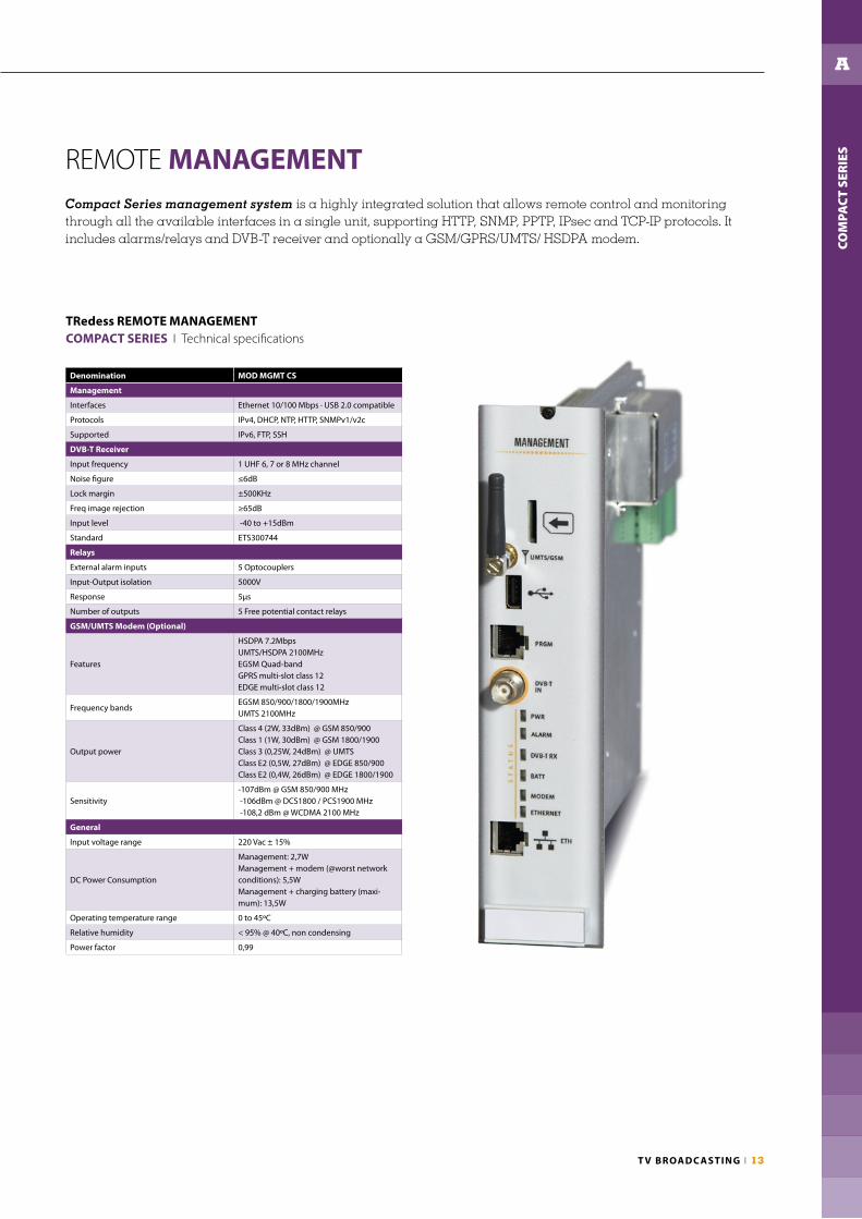
Compact Series management system is a highly integrated solution that allows remote control and monitoring through all the available interfaces in a single unit, supporting HTTP, SNMP, PPTP, IPsec and TCP-IP protocols. It includes alarms/relays and DVB-T receiver and optionally a GSM/GPRS/UMTS/ HSDPA modem.
REMOTE MANAGEMENT
Denomination MOD MGMT CS
Management
Interfaces Ethernet 10/100 Mbps · USB 2.0 compatible
Protocols IPv4, DHCP, NTP, HTTP, SNMPv1/v2c
Supported IPv6, FTP, SSH
DVB-T Receiver
Input frequency 1 UHF 6, 7 or 8 MHz channel
Noise fi gure ≤6dB
Lock margin ±500KHz
Freq image rejection ≥65dB
Input level -40 to +15dBm
Standard ETS300744
Relays
External alarm inputs 5 Optocouplers
Input-Output isolation 5000V
Response 5µs
Number of outputs 5 Free potential contact relays
GSM/UMTS Modem (Optional)
Features
HSDPA 7.2MbpsUMTS/HSDPA 2100MHzEGSM Quad-bandGPRS multi-slot class 12EDGE multi-slot class 12
Frequency bandsEGSM 850/900/1800/1900MHzUMTS 2100MHz
Output power
Class 4 (2W, 33dBm) @ GSM 850/900Class 1 (1W, 30dBm) @ GSM 1800/1900Class 3 (0,25W, 24dBm) @ UMTSClass E2 (0,5W, 27dBm) @ EDGE 850/900Class E2 (0,4W, 26dBm) @ EDGE 1800/1900
Sensitivity-107dBm @ GSM 850/900 MHz -106dBm @ DCS1800 / PCS1900 MHz -108,2 dBm @ WCDMA 2100 MHz
General
Input voltage range 220 Vac ± 15%
DC Power Consumption
Management: 2,7WManagement + modem (@worst network conditions): 5,5WManagement + charging battery (maxi-mum): 13,5W
Operating temperature range 0 to 45ºC
Relative humidity < 95% @ 40ºC, non condensing
Power factor 0,99
TRedess REMOTE MANAGEMENTCOMPACT SERIES I Technical specifi cations

COM
PAC
T SE
RIE
S
A
14 I TREDESS
EQUIPMENT FOR DIGITAL TERRESTRIAL TV COMPACT SERIES
Compact Series provides a complete synchronization system in a 19”x1HU, composed by one or two GPS receivers (optional GPS redundancy) and a GPS splitter. GPS splitters are stackable, so that the 1pps and 10MHz synchronization signals can be supplied to all the equipment.
SYNCHRONIZATION
Denomination MOD GPS CS
Frequency output (10 MHz)
Accuracy: with GPS(average over 24 hours when GPS locked)
< ±1 × 10 exp−12 Hz
Accuracy: without GPS < ±2 Hz
Medium Term Stability(without input reference, constant temp., after 2 weeks of continuous operation locked on input source)
< ±2 × 10 exp−10/day
Short time stability (Allan Variance)1x10 exp -11 @ 1s3x10 exp -11 @ 10s & 100s
Temperature Stability (peak to peak) 1 × 10 exp−9 (from -5ºC to 70ºC)
Phase noise (typical, static conditions)- 120 dBc/Hz @ 10Hz- 135 dBc/Hz @ 100Hz- 145 dBc/Hz @ 1kHz, 10kHz & 100kHz
Harmonic distortion −40dBc
Signal Waveform / Impedance Sine wave / 50 Ω
Time output (1PPS)
Accuracy to UTC (GPS locked) ±25ns (1σ)
Holdover Mode after 4 hours 0.8μs
Holdover Mode after 1 day(at constant temp., after 24 hours of GPS lock)
12μs
Signal Waveform / Impedance TTL / 50 Ω
Operating mode
Cold start-up time < 20 minutes
Hot start-up time < 5 minutes
Permanent self-test of main function Yes
Interfaces
Antenna input connector BNC female
Antenna input inpedance 50 Ω
Output 10MHz/1PPS & data: DIN 41612 32pins 2A male
Antenna
Frequency range 1575,42 MHz ± 1.023 MHz
Gain 35 dB typical
Noise fi gure < 2.2 dB (1.8dB typical)
Out Band Rejection @ 1575.42 ± 50MHz 60dB typical
Power supply 5V/27mA
Operating Temperature -40ºC to 85ºC
Relative humidity <95% @ 40ºC, non condensing
Connector N female
Impedance 50 Ω
Denomination MOD SPLITTER GPS CS
Switching unit
Frequency (10 MHz) inputs 3 redundant (2 from GPS + 1 external)
Frequency (10 MHz) outputs 8
External input (10MHz) connector BNC female
External input (10MHz) impedance 50Ω
Output (10MHz) connector BNC female
Output (10MHz) impedance 50Ω
Output (10MHz) level (from GPS receiver) -2.5dBm ± 1.5dB
10MHz insertion losses < 4 dB
Time (1 pps) inputs 3 redundant (2 from GPS + 1 external)
Time (1 pps) outputs 8
External input (1pps) connector BNC female
External input (1pps) impedance 50Ω
Output (1pps) connector BNC female
Output (1pps) impedance 50Ω
Output (1 pps) signal TTL
Power supply
DC input voltage 27 ± 0,3 VDC
DC input voltage connector2 x SMD power jack male (2.1mm ID, 5.5mm OD)
DC voltage reset connector 2 x SMD jack female (2.5mm)
DC Power Consumption
GPS switcher without GPS receivers 3W
GPS switcher with 2 GPS receivers (at 25ºC) 15W
GPS switcher with 2 GPS receivers (during warm-up time)
20W
Temperature
Operating temperature 0 to 45º
Relative humidity <95% @ 40ºC, non condensing
Dimensions
GPS splitter (WxHxD) 483 x 43 x 166 mm
GPS receiver (WxHxD) 483 x 43 x 166 mm
Antenna GPS (External diameter) 90 mm
Antenna GPS (Heigh without connector) 98.4 mm
Weight
GPS switcher 2,8 Kg
GPS receiverer (WxHxD) 0,6 Kg
Antenna GPS 0,3 Kg
TRedess GPS RECEIVERCOMPACT SERIES I Technical specifi cations
TRedess SPLITTER GPSCOMPACT SERIES I Technical specifi cations

COM
PAC
T SE
RIE
S
A
T V BROADC ASTING I 15
The TRedess Compact systems offer two redundancy solutions: 1+1 and N+1.
In a system with 1+1 redundancy, every channel has a spare unit in hot stand-by status. If a multiplex meets any of the switching criteria, the system automatically switches to its spare channel.
In a system with N+1 redundancy, one spare channel is in hot stand-by status. If any of the N multiplex meets at least one of the switching criteria, the system automatically confi gures the spare channel and performs the switching.
The system can be confi gured for auto-recovering its original status when the switching criteria condition has been cleared. In multiple fault case (N+1 only) switching priorities can be established. The switching criteria are based on different alarms and are user confi gurable.
REDUNDANCY
Denomination MOD UCA N+1 TX CS MOD UCA N+1 GF CS
Input distribution/switching
ASI inputs 6 + 1 (loop from another UCAN+1) -
RF inputs - 2
Input connector BNC female
Input impedance 75 Ω 50 Ω
ASI outputs 6 + 1 (reserve) -
Relay Type Latch with indication of state -
RF outputs - 8
Switching RF output
Output connector SMA female
Output impedance 50 Ω
Maximum Number of relays 6
Relay Type Latch with indication of state
Insertion Loss < 0.2dB
Return loss > 20dB
Isolation between inputs 70dB
Maximum power 100W @ 1 GHz
General
Power supply 27V
Input power connector Jack male
Output power connector Jack male
Consumption 3W
Peak consumption 7W (100 ms)
Temperature range 0º to 45ºC
Dimensions 482 (19”) x 43(1U) x 90 mm
TRedess REDUNDANCY I COMPACT SERIES I Technical specifi cations

16 I TREDESS
EQUIPMENT FOR DIGITAL TERRESTRIAL TV COMPACT SERIES
COM
PAC
T SE
RIE
S
A
Compact Series provides a complete satellite reception system in a 19”x1HU, composed by four dual satellite tuners implemented in a multi-switch platform with PLS scrambling functionality. With only 127mm depth, the satellite converter unit is DVB-S and DVB-S2, Single- and Multistream compatible. The satellite inputs support loop-through, so that a single satellite reception can provide the information for all the tuners.
DVB-S2/ASI Converter
Satellite Receiver
RF input frequency 950 to 2150 Mhz
Number of RF inputs 4
Number of RF loop-through outputs 4
Loop-through outputs insertion loss < 3dB
Input connector F female
Input impedance 75 Ω
Return losses > 11,5 dB
RF input power for a single carrier -80 dBm to -10 dBm
Roll-Off 0.2, 0.25, 0.35
DVB-S Demodulation
Constellation QPSK
Symbol rate [MSymbols/s] 1 to 45
FECAutomatic | 1/2, 2/3, 3/4, 5/6, 7/8
Viterbi and RS dual decoder
DVB-S2 Demodulation
ModesCCM, VCM and ACM, Single & Multi-stream, Normal
& Short FEC frames
Constellation QPSK, 8PSK, 16APSK and 32APSK
Symbol rate [MSymbols/s]
QPSK: 67.5 (Single), 47 (Dual)
8PSK: 63 (Single), 31.5 (Dual)
16APSK: 47 (Single)
32APSK: 38 (Single)
FEC
Automatic | 1/4, 1/3, 2/5, 1/2, 3/5, 2/3, 3/4, 4/5, 5/6,
8/9, 9/10
LDPC + BCH dual decoder
Denomination: DVB-S2 / ASI CONVERTER CS
ASI outputs
Number of outputs 7
Output connector BNC female
Output impedance 75 Ω
Transport stream formats 188 bytes structure | Byte or packet mode.
Max Transport stream bit rate 120 Mbit/s
General
DC input voltage 27 ± 3 VDC
DC input connector 2 x SMD power jack male (2.1mm ID, 5.5mm OD)
Reset connector 2 x SMD jack female (2.5mm)
Control connector 2 x SMD jack female (2.5mm)
Operating temperature range 0 to 45ºC
Relative humidity < 95% @ 40ºC, non condensing
Dimensions (WxHxD) 483 x 43 x 127 mm
Weight 1Kg
Directives & standards
R&TTE
1999/05/EC, EN 301489-1, EN 301489-14,
EN 60950-1:2006+A1:2010+A11:2009+A12:2011,
EN 60215:1989+A1:92+A2:94,
EN 61000-3-2:2006+A1+A2, EN 61000-3-3:2008,
EN 50364:2010, EN 50413:2008,
EN 62369-1:2011
RoHS 2011/65/EU
Standards EN 300421, EN 302307, EN 50083-9
TRedess DVB-S2/ASI CONVERTER I COMPACT SERIES I Technical specifi cations

T V BROADC ASTING I 17
COM
PAC
T SE
RIE
S
A
The TRedess Compact Series IP to ASI conversion system is based on an embedded Gigabit Ethernet switch with two GbE ports. The 19” x 1HU x 127mm IP/ASI CONVERTER unit can generate up to seven Transport Streams, using single or multiple IP addresses.
IP/ASI Converter
Denomination: IP / ASI CONVERTER CS
TRedess IP/ASI CONVERTER I COMPACT SERIES I Technical specifi cations
GbE Port
Physical Layer IEEE 802.3af
Data Rate 10/100/1000 base-T
Input connectors RJ-45
Number of inputs2
(1 also working as loop-through output)
Port capabilities Switch GbE
ASI Port
Physical Layer DVB-ASI
Number of outputs 7
Output connector BNC female
Impedance 75Ω
Data Rate 270 Mbps
Return losses >15 dB @ 270 MHz
Transport Stream
TS per IP Up to 7
Encapsulation UDP / RTP
Network protocols
IP-address assignment DHCP or static
Number of IP addresses Up to 7
Multicast IGMP v2
Protocols IPv4, RTP, UDP
General
DC Input voltage 27 ± 3 VDC
DC Input connector 2 x SMD power jack male (2.1mm ID, 5.5mm OD)
Reset connector 2 x SMD jack female (2.5mm)
Control connector 2 x SMD jack female (2.5mm)
Operating temperature range 0 to 45ºC
Relative humidity < 95% @ 40ºC, non condensing
Dimensions (WxHxD) 483 x 43 x 127 mm
Weight 1Kg
Directives & standards
R&TTE
1999/05/EC, EN 301489-1, EN 301489-14,
EN 60950-1:2006+A1:2010+A11:2009+A12:2011,
EN 60215:1989+A1:92+A2:94,
EN 61000-3-2:2006+A1+A2, EN 61000-3-3:2008,
EN 50364:2010, EN 50413:2008,
EN 62369-1:2011
RoHS 2011/65/EU
StandardsEN 50083-9, TS 102 034, ISO/IEC 13818RFC 1122, RFC 791, RFC 768, RFC 3550,SMPTE 2022
18 I TREDESS
EQUIPMENT FOR DIGITAL TERRESTRIAL TV COMPACT SERIES
COM
PAC
T SE
RIE
S
A
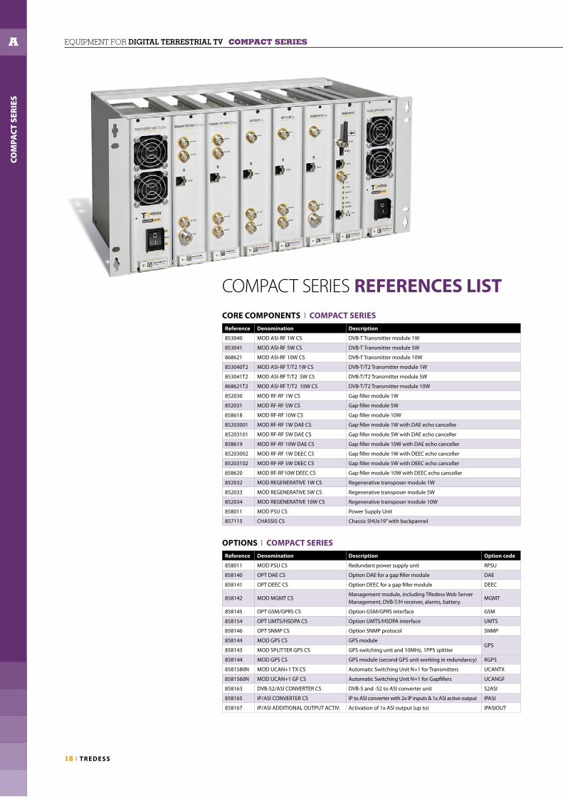
CORE COMPONENTS I COMPACT SERIESReference Denomination Description
853040 MOD ASI-RF 1W CS DVB-T Transmitter module 1W
853041 MOD ASI-RF 5W CS DVB-T Transmitter module 5W
868621 MOD ASI-RF 10W CS DVB-T Transmitter module 10W
853040T2 MOD ASI-RF T/T2 1W CS DVB-T/T2 Transmitter module 1W
853041T2 MOD ASI-RF T/T2 5W CS DVB-T/T2 Transmitter module 5W
868621T2 MOD ASI-RF T/T2 10W CS DVB-T/T2 Transmitter module 10W
852030 MOD RF-RF 1W CS Gap fi ller module 1W
852031 MOD RF-RF 5W CS Gap fi ller module 5W
858618 MOD RF-RF 10W CS Gap fi ller module 10W
85203001 MOD RF-RF 1W DAE CS Gap fi ller module 1W with DAE echo canceller
85203101 MOD RF-RF 5W DAE CS Gap fi ller module 5W with DAE echo canceller
858619 MOD RF-RF 10W DAE CS Gap fi ller module 10W with DAE echo canceller
85203002 MOD RF-RF 1W DEEC CS Gap fi ller module 1W with DEEC echo canceller
85203102 MOD RF-RF 5W DEEC CS Gap fi ller module 5W with DEEC echo canceller
858620 MOD RF-RF10W DEEC CS Gap fi ller module 10W with DEEC echo canceller
852032 MOD REGENERATIVE 1W CS Regenerative transposer module 1W
852033 MOD REGENERATIVE 5W CS Regenerative transposer module 5W
852034 MOD REGENERATIVE 10W CS Regenerative transposer module 10W
858011 MOD PSU CS Power Supply Unit
857115 CHASSIS CS Chassis 5HUx19” with backpannel
OPTIONS I COMPACT SERIESReference Denomination Description Option code
858011 MOD PSU CS Redundant power supply unit RPSU
858140 OPT DAE CS Option DAE for a gap fi ller module DAE
858141 OPT DEEC CS Option DEEC for a gap fi ller module DEEC
858142 MOD MGMT CSManagement module, including TRedess Web Server Management, DVB-T/H receiver, alarms, battery.
MGMT
858145 OPT GSM/GPRS CS Option GSM/GPRS interface GSM
858154 OPT UMTS/HSDPA CS Option UMTS/HSDPA interface UMTS
858146 OPT SNMP CS Option SNMP protocol SNMP
858144 MOD GPS CS GPS moduleGPS
858143 MOD SPLITTER GPS CS GPS switching unit and 10MHz, 1PPS splitter
858144 MOD GPS CS GPS module (second GPS unit working in redundancy) RGPS
8581580N MOD UCAN+1 TX CS Automatic Switching Unit N+1 for Transmitters UCANTX
8581560N MOD UCAN+1 GF CS Automatic Switching Unit N+1 for Gapfi llers UCANGF
858163 DVB-S2/ASI CONVERTER CS DVB-S and -S2 to ASI converter unit S2ASI
858165 IP/ASI CONVERTER CS IP to ASI converter with 2x IP inputs & 1x ASI active output IPASI
858167 IP/ASI ADDITIONAL OUTPUT ACTIV. Activation of 1x ASI output (up to) IPASIOUT
COMPACT SERIES REFERENCES LIST

T V BROADC ASTING I 19
COM
PAC
T SE
RIE
S
A
COMPACT SERIES ORDERING INFORMATIONCompact Series equipment is fully confi gurable, being possible to combine the modules in a mixed equipment and customize to your needs with additional options and features. The following naming convention can be used to give a description of the components and options required. Based on them, we will design the best equipment confi guration for you.
EXAMPLES
CS_ EEnC_ pW (code for the equipment description) p = power in Watts (up to 10)
EE = type of equipment: TX (transmitter), GF (gap fi ller), RT (regenerative transposer) n = number of channels
CS = Indicator for Compact Series
Options: Option codes (see options table)
5W, 3 channels transmitter.1W, 2 channels gap fi ller.1W, 2 channels regenerative transposer.
CS_TX3C_ 5WCS_GF2C_ 1WCS_RT2C_ 1W
5W, 6 channels gap fi ller with DEEC and redundant power supply:
CS_GF6C_5WOptions: RPSU, DEEC
10W, 4 channels regenerative transposer with remote management including SNMP:
CS_RT4C_10W_MGMT Options: MGMT, SNMP
MO
D P
SU C
S
MO
D A
SI-R
F 5W
CS
MO
D A
SI-R
F 5W
CS
MO
D A
SI-R
F 5W
CS
MO
D R
F-R
F 1W
CS
MO
D R
F-R
F 1W
CS
MO
D R
EGEN
. 1W
CS
MO
D R
EGEN
. 1W
CS
MO
D P
WS
CS
MO
D R
F-R
F 5W
DEE
C C
S
MO
D R
F-R
F 5W
DEE
C C
S
MO
D R
F-R
F 5W
DEE
C C
S
MO
D R
F-R
F 5W
DEE
C C
S
MO
D R
F-R
F 5W
DEE
C C
S
MO
D R
F-R
F 5W
DEE
C C
S
MO
D P
WS
CS
MO
D P
WS
CS
MO
D R
EGEN
. 10W
CS
MO
D R
EGEN
. 10W
CS
MO
D R
EGEN
. 10W
CS
MO
D R
EGEN
. 10W
CS
MO
D M
GM
T +
SN
MP
CS

BR
OA
DC
AST
SER
IES
B
20 I TREDESS
EQUIPMENT FOR DIGITAL TERRESTRIAL TV BROADCAST SERIES
Technical description
Equipment from the Broadcast Series are developed to expand DTT covering areas where direct terrestrial signal reception is not possible.
In Broadcast Series there are output power options from 5W to 50W. The equipment modules are placed into a 19” x 5HU subrack. Each transmitter consists of a DVB-T/T2 modulator module and a power amplifier.
A 19” subrack can house up to three 5W transmitters/gap fillers and up to two 10W, 20W, 50W or 100W of them.
The Broadcast Series are based on a modular concept, using separate modules for power amplification and digital processing: modulator (transmitter) and channel processor (gap filler).
Main Characteristics
• Up to 100W Transmitters and Gap Fillers.• DVB-T/T2 compliant.• Two very high-performance echo cancellation options.• SFN and MFN configurations.• SFN synchronization system (GPS).• Redundancy system N+1, 1+1.• Remote control & monitoring system.• Frequency agility.• Low power consumption.• Very low phase noise oscillator. DDS Technology.• LDMOS amplifiers.• Independent operating mode.• Electromagnetic compatibility and safety according to the CE regulation norms.
BROADCAST SERIESTRANSMITTERS & GAP FILLERS

BR
OA
DC
AST
SER
IES
B
T V BROADC ASTING I 21
Two multiplex 100W modular DVB-T/T2 Broadcast Series transmitter
Two multiplex 50W modular DVB-T/T2 Broadcast Series gap fi ller

Two multiplex 100W modular DVB-T/T2 Broadcast Series transmitter
22 I TREDESS
EQUIPMENT FOR DIGITAL TERRESTRIAL TV BROADCAST SERIES
TRANSMITTERS
BR
OA
DC
AST
SER
IES
B
Two multiplex 10W modular DVB-T/T2 Broadcast Series transmitter

T V BROADC ASTING I 23
TRedess DVB-T TRANSMITTERS 5W, 10W, 20W, 50W I BROADCAST SERIES I Technical specifications
BR
OA
DC
AST
SER
IES
B
Reference DVB-T transmitter 853012 853013 853014 853010 853011 853018 853019 853031 853032
Denomination TXGB VF nC-5W TXGB nC-10W TXGB nC-20W TXGB nC-50W
Technical Specifications
Components
Power supply unit 1 1 1 1 2 1 2 1 2
DVB-T Modulator (n) 1 2 3 1 2 1 2 1 2
Power amplifier 1 2 3 1 2 1 2 1 2
DVB-T Modulator. Modes.
FFT 2K, 8K
Guard interval 1/4, 1/8, 1/16, 1/32
FEC 1/2, 2/3, 3/4, 5/6, 7/8
Constellation QPSK, 16 QAM, 64 QAM
Network MFN & SFN
Bandwidth 6, 7, 8 MHz
DVB-T Modulator. Inputs
MPEG2 / MPEG4 2 ASI seamless (redundant)
Impedance 75 Ω
Connector BNC Female
10MHz synchronization input
Input level -15 dBm to +10 dBm
Impedance 50 Ω
Connector BNC female (back of module)
1pps synchronization input
Level 0 - 5 V
Trigger Selected by rise-edge or fall-edge
Connector BNC female (back of module)
Local Oscillators
Phase noise ≥90 dBc/Hz @ 1kHz
Frequency stability with temperature (-10º to 60ºC) (without external GPS input)
Standard: ± 1 x 10e-6 Optional: ± 1 x 10e-7
Frequency stability for a year (without external GPS input)
Standard: ± 1 x 10e-6 Optional: ± 1 x 10e-7
RF output
Frequency range 1 UHF 8 MHz channel
Maximum output power [W] 7,9 W 15 W 31,6 W 80 W
Maximum output power [dBm] 39 dBm 41,75 dBm 45 dBm 49 dBm
Distance to the shoulders >38 dB
MER >34 dB
Power stability ≤ ± 0,5 dB
Return losses > 20 dB
Spurious emissions out of channel < -60 dBc
Impedance 50 Ohm
Connector BNC Female N Female
RF test output
Coupling 27 ± 3dB 42 ± 3dB 43 ± 3dB
Connector BNC Female
IF test output
Output level -35 dBm
Central frequency of the channel 36,15 MHz
Connector SMB Female
Local oscillator test output
Output level -30 ± 3 dBm
Connector SMB Female
General
Control and monitoring Ethernet, Relays · IP, HTTP, FTP, GSM/GPRS, UMTS/HSDPA, SNMP
Input voltage range 220 Vac ± 15%
DC Power Consumption * 85W 170W 255W 125W 250W 160W 320W 400W 800W
Operating temperature range 0 to 45ºC
Relative humidity (max.) 95%, non condensing
Power factor 0,60 0,99
Dimensions [width x height x depth] Up to 3 tx. in [19’’x5HUx250mm] Up to 2 transmitters in [19’’x5HUx250mm]
Weight 6’5kg 9kg 11’5kg 9kg 18kg 9kg 18kg 9kg 18kg
Cooling Active (forced ventilation)
Directives & standards
R&TTE1999/5/EC, EN 301489-1, EN 301489-14, EN 60950, EN 60215:1989+A1:92+A2:94, EN 61000-3-2: 2006 + A1 + A2, EN 61000-3-3: 2008,
EN 302296-2, 1999/519/EC
RoHS 2011/65/EU
Standards EN 300744, EN 302304, TS 101191, EN 50083-9, TR 101290, TS 102 773, TS 102 831
* DC Power Consumption is specified at the Maximum Output Power transmitted for every power range.

24 I TREDESS
DIG
ITA
L T
V ·
CO
MPA
CT
SER
IES
A
24 I TREDESS
BR
OA
DC
AST
SER
IES
B EQUIPMENT FOR DIGITAL TERRESTRIAL TV BROADCAST SERIES
Reference DVB-T/T2 transmitter 853012T2 853013T2 853014T2 853010T2 853011T2 853018T2 853019T2 853031T2 853032T2 853042T2 853043T2
Denomination TXGB VF nC-5W TXGB nC-10W TXGB nC-20W TXGB nC-50W TXGB nC-100W
Technical Specifications
Components
Power supply unit 1 1 1 1 2 1 2 1 2 1 2
DVB-T/T2 Modulator (n) 1 2 3 1 2 1 2 1 2 1 2
Power amplifier 1 2 3 1 2 1 2 1 2 1 2
DVB-T Modulator. Modes.
FFT 2K, 8K
Guard interval 1/4, 1/8, 1/16, 1/32
FEC 1/2, 2/3, 3/4, 5/6, 7/8
Constellation QPSK, 16 QAM, 64 QAM
Network MFN & SFN
Bandwidth 6, 7, 8 MHz
DVB-T2 Modulator. Modes
FFT 1K, 2K, 4K, 8K, 16K, 32K (normal or extended)
Guard interval 1/4, 19/256, 1/8, 19/128, 1/16, 1/32, 1/128
FEC 1/2, 3/5, 2/3, 3/4, 4/5, 5/6
Constellation QPSK, 16 QAM, 64 QAM, 256 QAM (normal or rotated)
Network MFN & SFN
Bandwidth 1.7, 5, 6, 7, 8 MHz
Input modes TS (SPLP) over ASI · T2MI (SPLP & MPLP*) over ASI
PLPs Up to 8 PLPs
Pilot patterns PP1 to PP8
Efficiency mode Normal & High
Operation mode SISO and/or MISO
DVB-T/T2 Modulator. Inputs
MPEG2 / MPEG4 2 ASI seamless (DVB-T mode). 2 ASI redundant (DVB-T2 mode).
Impedance 75 Ω
Connector BNC Female
10MHz synchronization input
Input level -20 dBm to +10 dBm
Impedance 50 Ω
Connector BNC female (back of module)
1pps synchronization input
Level 0 - 5 V
Trigger Selected by rise-edge or fall-edge
Connector BNC female (back of module)
Local Oscillators
Phase noise ≥90 dBc/Hz @ 1kHz
Frequency stability with temperature (-10º to 60ºC) (without external GPS input)
Standard: ± 1 x 10e-6Optional: ± 1 x 10e-7
Frequency stability for a year (without external GPS input)
Standard: ± 1 x 10e-6 Optional: ± 1 x 10e-7
Continues in the next page
TRedess DVB-T/T2 TRANSMITTERS 5W, 10W, 20W, 50W, 100W I BROADCAST SERIES I Technical specifications (part 1 of 2)

DIG
ITA
L T
V ·
CO
MPA
CT
SER
IES
A
T V BROADC ASTING I 25
BR
OA
DC
AST
SER
IES
B
Reference DVB-T/T2 transmitter 853012T2 853013T2 853014T2 853010T2 853011T2 853018T2 853019T2 853031T2 853032T2 853042T2 853043T2
Denomination TXGB VF nC-5W TXGB nC-10W TXGB nC-20W TXGB nC-50W TXGB nC-100W
Technical Specifications
RF output
Frequency range 1 UHF 6, 7 or 8 MHz channel
Maximum output power [W] 7,9 W 15 W 31,6 W 100 W 120 W
Maximum output power [dBm] 39 dBm 41,75 dBm 45 dBm 50 dBm 50,8 dBm
Distance to the shoulders >38 dB
MER >35 dB
Precorrection Digital
Power stability ≤ ± 0,5 dB
Return losses > 20 dB
Spurious emissions out of channel < -60 dBc
Impedance 50 Ohm
Connector BNC Female N Female
RF test output
Coupling 27 ± 3dB 27 ± 3dB 42 ± 3dB 43 ± 3dB 43 ± 3dB
Connector BNC Female
IF test output
Output level -35 dBm
Central frequency of the channel 36,15 MHz
Connector SMB Female
Local oscillator test output
Output level -30 ± 3 dBm
Connector SMB Female
General
Control and monitoring Ethernet, Relays · IP, HTTP, FTP, GSM/GPRS, UMTS/HSDPA, SNMP
Input voltage range 220 Vac ± 15%
DC Power Consumption * 85W 170W 255W 125W 250W 160W 320W 400W 800W 600W 1200 W
Operating temperature range 0 to 45ºC
Relative humidity (max.) 95%, non condensing
Power factor 0,60 0,99
Dimensions [width x height x depth] Up to 3 tx. in [19’’ x 5HU x 250mm] Up to 2 transmitters in [19’’ x 5HU x 250mm]
Weight 6’5kg 9kg 11’5kg 9kg 18kg 9kg 18kg 9kg 18kg 9kg 18kg
Cooling Active (forced ventilation)
Directives & standards
R&TTE1999/5/EC, EN 301489-1, EN 301489-14, EN 60950, EN 60215:1989+A1:92+A2:94, EN 61000-3-2: 2006 + A1 + A2, EN 61000-3-3: 2008,
EN 302296-2, 1999/519/EC
RoHS 2011/65/EU
Standards EN 300744, EN 302304, EN 302775, TS 101191, EN 50083-9, TR 101290, TS 102 773, TS 102 831
* DC Power Consumption is specified at the Maximum Output Power transmitted for every power range.
TRedess DVB-T/T2 TRANSMITTERS 5W, 10W, 20W, 50W, 100W I BROADCAST SERIES I Technical specifications (part 2 of 2)
Continuation from the previous page

Three multiplex 5W modular DVB-T/T2 Broadcast Series gap fi ller
Two multiplex 50W modular DVB-T/T2 Broadcast Series gap fi ller
GAP FILLERS
26 I TREDESS
EQUIPMENT FOR DIGITAL TERRESTRIAL TV BROADCAST SERIES
BR
OA
DC
AST
SER
IES
B

TRedess DVB-T/T2 GAP-FILLERS 5W, 10W, 20W, 50W I BROADCAST SERIES I Technical specifications
T V BROADC ASTING I 27
BR
OA
DC
AST
SER
IES
B
References Gap-filler 851018 851019 851020 851016 851017 851024 851025 851031 851032
Denomination RXGB VF nC-5W RXGB nC-10W RXGB nC-20W RXGB nC-50W
References Gap-filler with DAE 852013 852014 - 852016 852017 85102401 85102501 - -
References Gap-filler with DEEC 851052 851053 851054 851046 851047 851048 851049 851044 851045
Technical Specifications
Components
Power supply unit 1 1 2 1 2 1 2 1 2
Channel processor 1 2 3 1 2 1 2 1 2
Power amplifier 1 2 3 1 2 1 2 1 2
RF input
Frequency range 1 UHF 8 MHz Channel
Input signal range -70 to -20 dBm
Noise figure < 8 dB
Return losses > 20 dB (with DAE) • > 15 dB (with DEEC)
Frequency image rejection > 90 dB (with DAE) • > 65 dB (with DEEC)
Adjacent channel rejection > 80 dB
Impedance 50 Ω
Connector BNC Female
DAE (Digital Adaptive Equalizer)
Gain Margin (signal - echo) -10 dB
Cancellation window 0 - 8 µs
Output power adaptive regulation Yes
IF TEST INPUT
Input signal range -30 to -10 dBm
Input central frequency 36,125 MHz
Connector SMB Female
IF TEST OUTPUT
Output level -30 ± 3 dB
Connector SMB Female
Local oscillator test output
Output level -30 ± 3 dB
Connector SMB Female
DEEC (Doppler Enhanced Echo Canceller)
Gain Margin (signal - echo) -24 dB
Cancelation window 3 configurable cancellation windows • Selective cancellation up to 37,6 µs
Doppler cancellation Yes
External synchronization input
Frequency 10 MHz
Input level range -10 to +10 dBm (with DAE) • -20 to +10 dBm (with DEEC)
Connector BNC Female
Local oscillators
Phase noise > 90 dBc/Hz @ 1KHz (in MFN mode). Negligible in SFN mode.
Frequency stability with temperature (-10º to 60ºC) (without external GPS input)
± 1 x 10e-6
Frequency stability for a year (without external GPS input)
± 1 x 10e-6
RF output
Frequency range 1 UHF 8 MHz Channel
Maximum output power [W] 7,9 W 15 W 31,6 W 80 W
Maximum output power [dBm] 39 dBm 41,75 dBm 45 dBm 49 dBm
Distance to the shoulders >38 dB
Power stability ± 0,5 dB
Return losses >20 dB
Spurious emissions out of channel <-60 dBc
Impedance 50 Ω
Connector BNC Female N Female
RF test output
Coupling 27 ± 3dB 27 ± 3dB 42 ± 3dB 43 ± 3dB
Connector BNC Female
General
Control and monitoring Ethernet, Relays · IP, HTTP, FTP, GSM/GPRS, UMTS/HSDPA, SNMP
Input voltage range 220 Vac ± 15%
DC Power Consumption * 85W 170W 255W 125W 250W 160W 320W 400W 800W
Operating temperature range 0 to 45ºC
Relative humidity (max.) 95%, non condensing
Power factor 0,60 0,99
Dimensions [width x height x depth] Up to 3 gf. in [19’’ x 5HU x 250mm] Up to 2 gap-fillers in [19’’ x 5HU x 250mm]
Weight 6kg 8,5kg 13kg 9kg 18kg 9kg 18kg 9kg 18kg
Cooling Active (forced ventilation)
Directives & standards
R&TTE1999/5/EC, EN 301489-1, EN 301489-14, EN 60950, EN 60215:1989+A1:92+A2:94, EN 61000-3-2: 2006 + A1 + A2, EN 61000-3-3: 2008,
EN 302296-2, 1999/519/EC
RoHS 2011/65/EU
Standards EN 300744, EN 302304, EN 302775, TS 101191, EN 50083-9, TR 101290, TS 102 773, TS 102 831
* DC Power Consumption is specified at the Maximum Output Power transmitted for every power range.
28 I TREDESS
EQUIPMENT FOR DIGITAL TERRESTRIAL TV BROADCAST SERIES
REMOTE MANAGEMENT
Technical description
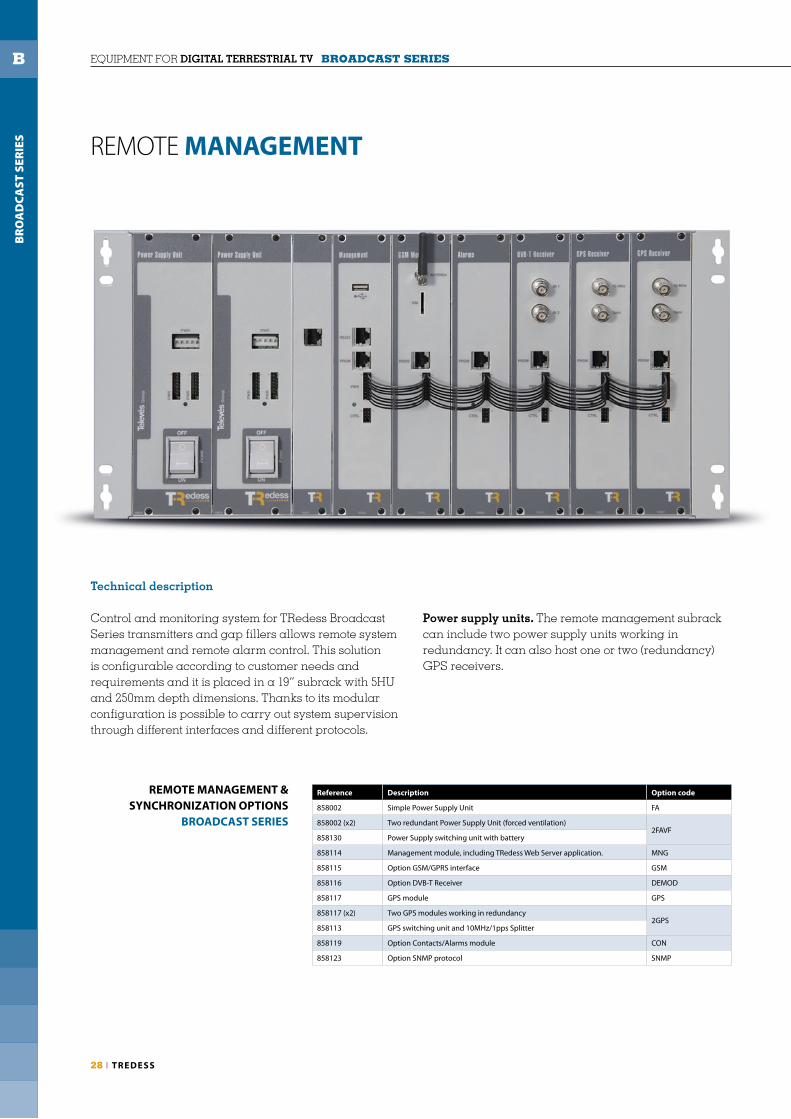
Control and monitoring system for TRedess Broadcast Series transmitters and gap fi llers allows remote system management and remote alarm control. This solution is confi gurable according to customer needs and requirements and it is placed in a 19” subrack with 5HU and 250mm depth dimensions. Thanks to its modular confi guration is possible to carry out system supervision through different interfaces and different protocols.
Power supply units. The remote management subrack can include two power supply units working in redundancy. It can also host one or two (redundancy) GPS receivers.
BR
OA
DC
AST
SER
IES
B
REMOTE MANAGEMENT & SYNCHRONIZATION OPTIONS
BROADCAST SERIES
Reference Description Option code
858002 Simple Power Supply Unit FA
858002 (x2) Two redundant Power Supply Unit (forced ventilation)2FAVF
858130 Power Supply switching unit with battery
858114 Management module, including TRedess Web Server application. MNG
858115 Option GSM/GPRS interface GSM
858116 Option DVB-T Receiver DEMOD
858117 GPS module GPS
858117 (x2) Two GPS modules working in redundancy2GPS
858113 GPS switching unit and 10MHz/1pps Splitter
858119 Option Contacts/Alarms module CON
858123 Option SNMP protocol SNMP

T V BROADC ASTING I 29
MANAGEMENT MODULE ALARMS DVB-T RECEIVERGSM/GPRS
It centralises the different system alarms and events from every detected module making a periodic checking. The Management unit supplies, without any additional module, remote control and monitoring through Ethernet and serial communication (HTTP, SNMP, PPTP, IPsec, TCP-IP).
Allows exporting system alarms using electrical relays, receiving remote control commands from external equipment through optical couplers and acting over external equipment using electrical relays.
It analyses DVB-T transmitted signals and informs to control module (Management) about their quality.
Technical Specifi cations
Hardware settings
Interfaces:Ethernet 10/100 MbpsUSB 2.0 compatibleRS232 external (modem)Local programmerRS485 (control bus)
Software settings
Protocols:IPv4, DHCP, NTP, HTTP, SNMP v1/v2c
Supported:IPv6, FTP, SSH
Applications:SNMP agentWeb serverVPN client
General
DC Power Consumption: 2W
Operating temp. range: 0 to 45ºC
Relative humidity:< 95% @ 40ºC, non condensing
Technical Specifi cations
DVB-T demodulator
Inputs: 2 x BNC female
Input frequency:174-230 / 474-858MHz
Noise fi gure: ≤6dB
Lock margin: ±500KHz
Freq image rejection: ≥65dB
Input level: -30 to +10dBm
Standard: ETS300744
General
DC Power Consumption: 4.5W
Operating temp. range: 0 to 45ºC
Relative humidity:< 95% @ 40ºC, non condensing
Technical Specifi cations
Modem
Frequency bands:EGSM 850/900/1800/1900MHz
Output power:2W @ 850/900MHz1W @ 1800/1900MHz
Sensitivity:-107dBm @ 850/900MHz-106 dBm @ 1800/1900MHz
General
DC Power Consumption:26µA (power off )< 4mA (power save)200mA (direct mode)370mA (max consumption mGPRS)
Operating temp. range: 0 to 45ºC
Relative humidity:< 95% @ 40ºC, non condensing
Connected to the remote control module (Management) through a serial port, it allows system communication through mobile networks.
Technical Specifi cations
Optocoupler inputs
External alarm inputs:15 (12 in connector2, 3 in connector1)
Input-Output isolation: 5000V
Response: 5µs
Outputs
Outputs:21 (9 in connector1, 12 in connector3)
Impedance: 75mΩ
Max power: 60W
Max voltage: 220Vdc, 125 Vac
Max current: 2A
Expected life: 10 exp 8 switchings
General
DC Power Consumption:50mW (per active input)70mW (per relay)
Operating temp. range: 0 to 45ºC
Relative humidity:< 95% @ 40ºC, non condensing
BR
OA
DC
AST
SER
IES
B

30 I TREDESS
EQUIPMENT FOR DIGITAL TERRESTRIAL TV BROADCAST SERIES
GPS MODULEFor transmitters and MFN-SFN gap fi llers we supply a GPS synchronization system that can work in redundancy. Synchronization signals (10MHz and 1pps) from each GPS module are distributed and switched through the GPS switching unit.
GPS SWITCHING UNITIt manages the 1pps and 10MHz synchronization signals received from the GPS modules, selecting the locked one. It includes the needed circuits for eight 10MHz and 1pps signals generation (all of them available through BNC connectors placed on the back side of the module).
It also informs about the power supply units’ status to the monitoring system.
GPS SWITCHING UNIT
BR
OA
DC
AST
SER
IES
B
SYNCHRONIZATION
Denomination MOD GPS BS
Frequency output (10 MHz)
Accuracy: with GPS (average over 24 hours when GPS locked) < ±1 × 10 exp−12 Hz
Accuracy: without GPS < ±2 Hz
Medium Term Stability(without input reference, constant temp., after 2 weeks of continuous operation locked on input source)
< ±2 × 10 exp−10/day
Short time stability (Allan Variance):1x10 exp -11 @ 1s3x10 exp -11 @ 10s & 100s
Temperature Stability (peak to peak) 1 × 10 exp−9 (from -5ºC to 70ºC)
Phase noise (typical, static conditions)- 120 dBc/Hz @ 10Hz- 135 dBc/Hz @ 100Hz- 145 dBc/Hz @ 1kHz, 10kHz & 100kHz
Harmonic distortion −40dBc
Signal Waveform / Impedance Sine wave / 50 Ω
Signal level 5 ± 2 dBm
Connector BNC female
Time output (1PPS)
Accuracy to UTC (GPS locked) ±25ns (1σ)
Holdover Mode after 4 hours 0.8μs
Holdover Mode after 1 day(at constant temp., after 24 hours of GPS lock)
12μs
Signal Waveform / Impedance TTL / 50 Ω
Connector BNC female
Operating mode
Cold start-up time < 20 minutes
Hot start-up time < 5 minutes
Permanent self-test of main function Yes
Interfaces
Antenna input connector BNC female
Antenna input inpedance 50 Ω
Antenna
Frequency range 1575,42 MHz ± 1.023 MHz
Gain 35 dB typical
Noise fi gure < 2.2 dB (1.8dB typical)
Out Band Rejection @ 1575.42 ± 50MHz 60dB typical
Power supply 5V/27mA
Operating Temperature −40ºC to 85ºC
Relative humidity <95% @ 40ºC, non condensing
Connector N female
Impedance 50 Ω
DC Power Consumption
Consumption (at 25ºC) 6,5 W
Consumption (during warm-up time) 9 W
Denomination MOD GPS SPLITTER BS
Switching unit
10MHz inputs 2 (redundant)
1PPS inputs 2 (redundant)
10MHz outputs 8
1PPS outputs 8
10MHz and 1PPS inputs and outputs connectors BNC female
10MHz and 1PPS inputs and outputs Impedance 50Ω
Insertion loss (10MHz) < 7 dB
General
Battery Lithium
Temperature range 0 to 45ºC
Dimensions (WxHxD) 482x43x90mm
Weight 1,5Kg
DC Power Consumption 2W
Relative humidity < 95% @ 40ºC, non condensing

T V BROADC ASTING I 31
The TRedess Broadcast systems offer two redundancy solutions: 1+1 and N+1.
In a system with 1+1 redundancy, every channel has a spare unit in hot stand-by status. If a multiplex meets at least one of the switching criteria, the system automatically switches to its spare channel.
In a system with N+1 redundancy, one spare channel is in hot stand-by status. If any of the N multiplex meets at least one of the switching criteria, the system automatically confi gures the spare channel and performs the switching.
The system can be confi gured for auto-recovering its original status when the switching criteria condition has been cleared. In multiple fault case (N+1 only) switching priorities can be established. The switching criteria are based on different alarms and are user confi gurable.
BR
OA
DC
AST
SER
IES
B
REDUNDANCY
Broadcast Series UCA N+1 redundancy
Broadcast Series UCA 1+1 redundancy
Reference 858126 858127
Denomination MOD UCA1+1 GB MOD UCAN+1 GB
Input distribution/switching
Switching input No Yes
Relay Type - Latch
Insertion Loss - < 1,5dB
Number of inputs 2 6
Input connector BNC female
Switching RF output
Relay Type Latch with indication of state Latch
Insertion Loss < 0.2dB
Return loss > 20dB
Isolation between inputs 70dB
Maximum power 100W @ 860MHz
Number of outputs 2 N (up to 6)
Output connector SMA female
Impedance 50 Ω
General
Power supply 13,5 V
Maximum consumption 5W
Input power connector Jack male
Output power connector Jack male -
Temperature range 0º to 45ºC
Dimensions 482(19”) x 43(1HU) x 90 mm
Weight 1,1 kg 1,6 kg
ECH
O C
AN
CEL
LIN
G
C
32 I TREDESS
EQUIPMENT FOR DIGITAL TERRESTRIAL TV ECHO CANCELLING
ECHO CANCELLING
Technical description
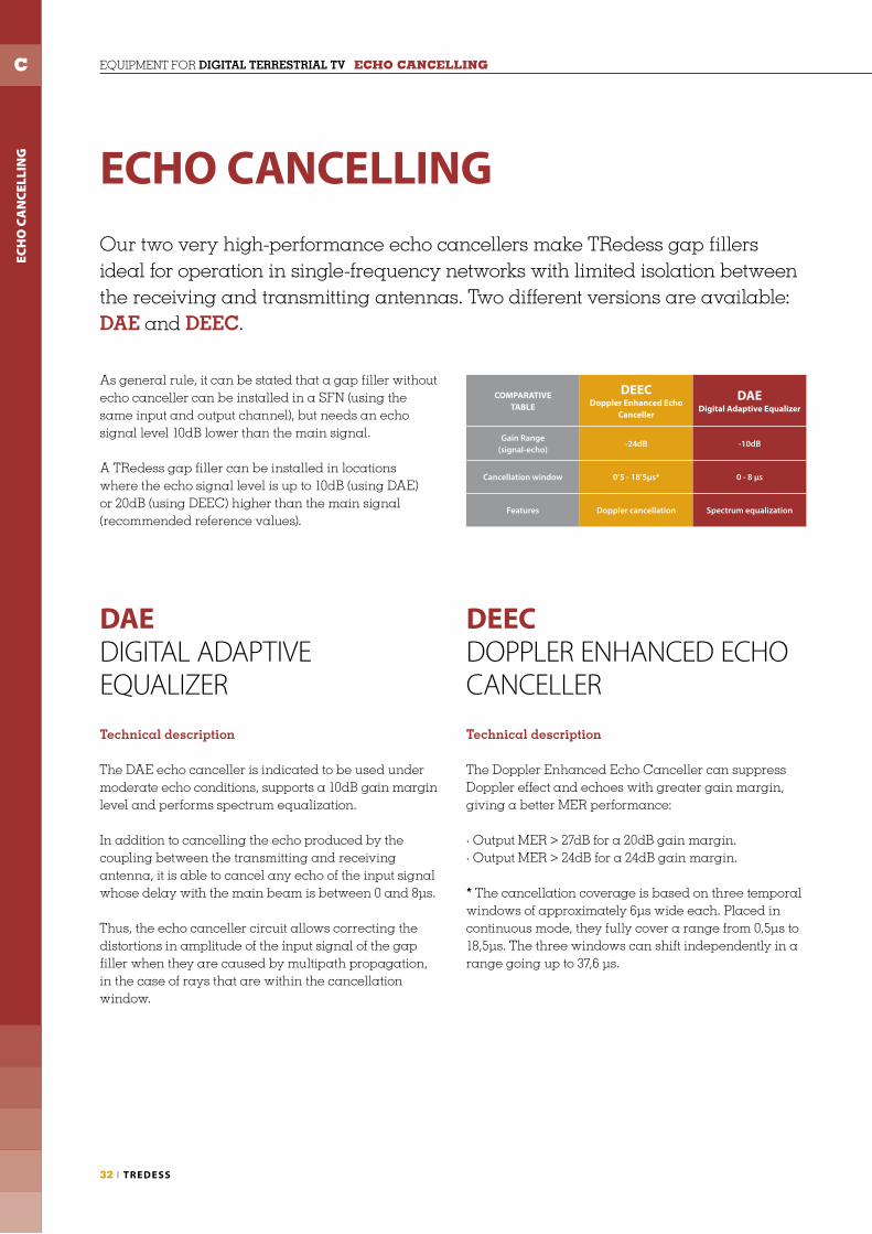
The DAE echo canceller is indicated to be used under moderate echo conditions, supports a 10dB gain margin level and performs spectrum equalization.
In addition to cancelling the echo produced by the coupling between the transmitting and receiving antenna, it is able to cancel any echo of the input signal whose delay with the main beam is between 0 and 8μs.
Thus, the echo canceller circuit allows correcting the distortions in amplitude of the input signal of the gap filler when they are caused by multipath propagation, in the case of rays that are within the cancellation window.
Technical description
The Doppler Enhanced Echo Canceller can suppress Doppler effect and echoes with greater gain margin, giving a better MER performance:
· Output MER > 27dB for a 20dB gain margin.· Output MER > 24dB for a 24dB gain margin.
* The cancellation coverage is based on three temporal windows of approximately 6μs wide each. Placed in continuous mode, they fully cover a range from 0,5μs to 18,5μs. The three windows can shift independently in a range going up to 37,6 μs.
Our two very high-performance echo cancellers make TRedess gap fillers ideal for operation in single-frequency networks with limited isolation between the receiving and transmitting antennas. Two different versions are available: DAE and DEEC.
As general rule, it can be stated that a gap filler without echo canceller can be installed in a SFN (using the same input and output channel), but needs an echo signal level 10dB lower than the main signal.
A TRedess gap filler can be installed in locations where the echo signal level is up to 10dB (using DAE) or 20dB (using DEEC) higher than the main signal (recommended reference values).
DAE DIGITAL ADAPTIVE EQUALIZER
DEEC DOPPLER ENHANCED ECHO CANCELLER
COMPARATIVETABLE
DEEC Doppler Enhanced Echo
Canceller
DAEDigital Adaptive Equalizer
Gain Range(signal-echo)
-24dB -10dB
Cancellation window 0’5 - 18’5µs* 0 - 8 µs
Features Doppler cancellation Spectrum equalization

ECH
O C
AN
CEL
LIN
G
C
T V BROADC ASTING I 33
DAE GRAPHSSpectrum equalization with DAE echo canceller.
Cancellation of an echo 20dB higher than the signal with DEEC echo canceller, with output MER > 27dB.
DEEC GRAPHS
ECH
O
ECH
O
SIG
NA
L
SIG
NA
L
Input signal
Input signal
Output signal
Output signal

REM
OTE
CO
NTR
OL
& M
ON
ITO
RIN
G
D EQUIPMENT FOR DIGITAL TERRESTRIAL TV REMOTE CONTROL & MONITORING
CONTROL AND MONITORING SYSTEMSThe Control and Monitoring system for TRedess transmitters and gap fi llers allows remote system management and remote alarm control. This solution is confi gurable according to customer needs and allows system supervision through different interfaces (Ethernet, serial communication, GPRS/HSDPA, electrical relays) and protocols (HTTP, SNMP, PPTP, IPSec, TCP/IP).
Third party equipment can be integrated in the monitoring system using the electrical relays.
TRedess systems can also be managed with the TRedess Web Server Management application tool.
34 I TREDESS

REM
OTE
CO
NTR
OL
& M
ON
ITO
RIN
G
D
TREDESS WEB SERVER MANAGEMENTTRedess equipments can be managed and controlled (local or remotely) with our Web Server Management application tool. Through an IP connection it is possible to confi gure and control the system (modules, alarms, …) and confi gure all the transmission parameters (IP settings, GSM/GPRS parameters, VPN, serial port).
Using its user friendly graphical interface it is possible to obtain all parameters details and internal diagrams, alarm log, module status, etc, and modify and upgrade the system.
SNMP MANAGEMENT
WEB SERVER MANAGEMENT
GSM/GPRS/UMTS/HSDPA MANAGEMENT
SERIAL PORT MANAGEMENT
SMS MANAGEMENT
T V BROADC ASTING I 35
REM
OTE
CO
NTR
OL
& M
ON
ITO
RIN
G
D EQUIPMENT FOR DIGITAL TERRESTRIAL TV REMOTE CONTROL & MONITORING
36 I TREDESS
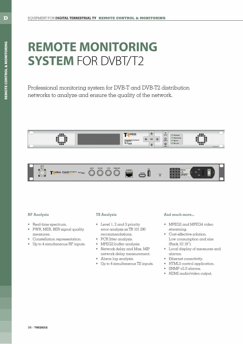
Professional monitoring system for DVB-T and DVB-T2 distribution networks to analyze and ensure the quality of the network.
RF Analysis
• Real-time spectrum.• PWR, MER, BER signal quality measures.• Constellation representation.• Up to 4 simultaneous RF inputs.
TS Analysis
• Level 1, 2 and 3 priority error analysis as TR 101 290 recommendations.• PCR Jitter analysis.• MPEG2 buffer analysis.• Network delay and Max. MIP network delay measurement.• Alarm log analysis.• Up to 4 simultaneous TS inputs.
And much more...
• MPEG2 and MPEG4 video streaming.• Cost-effective solution. Low consumption and size (Rack 1U 19”).• Local display of measures and alarms.• Ethernet conectivity.• HTML5 control application.• SNMP v2.0 alarms.• HDMI audio/video output.
REMOTE MONITORING SYSTEM FOR DVBT/T2

REM
OTE
CO
NTR
OL
& M
ON
ITO
RIN
G
D
T V BROADC ASTING I 37
MANAGEMENT SYSTEM
All-in-one visualization:Presents a brief system status. It shows spectrum, services, measures, alarms, PIDs... All integrated in a single view for quick analysis.
Web browser accesible control and presentation environment.
Services visualization:It shows in detail channel services ifnormation. Several views are confi gurable.
PID visualization:It shows a list of PIDs with ratio, bandwidth and several information.
Screenshots:It shows realtime captures of the monitored channel services.
Analyzer view:It represents the spectrum of the monitorized channel with detailed measures.
Alarm summary:It represents the alarms counter since the beggining of the monitorization.
Standards
ETSI EN 300 744 (DVB-T)ETSI EN 302 755 (DVB-T2) (opt.) ETSI TR 101 290
Inputs
RF1 x 50 Ω N connector4 x 50 Ω N connector (opt.)
RF Input frequency 47MHz a 1GHz
SYNC1 x 1PPS BNC 50 Ω10Mhz BNC 50 Ω
TS 1 x ASI IN BNC 50 Ω
Outputs
TS 1 x ASI OUT BNC 50 Ω
A/V 1 x HDMI
RF Measures
SpectrumSignal powerMERCBER, VBERLink Margin, BCHBER, LDPCBER (opt.)Carrier MER (opt.)Constelation (opt.)Echos (opc.)
MPEG Measures
Level 1,2 y 3 priority errorsMPEG2 buff er analysisAlarms log analysisPCR Jitter (opt.)Network delay (opt.)MIP network maximum delay (opt.)
Mechanical characteristics
1U 19” rackable unit.Size: 482mm W x 348mm D x 41mm HWorking temperature 0 a 40 ºCStorage temperature 0 a 50 ºC
Electrical characteristics
Input 100 - 240 VAC 50-60Hz 1.4A
Interfaces
1 x USB 2.01 x Ethernet RJ45LCD Graphic display
Control protocols
HTML & SNMP
REMOTE MONITORING SYSTEM FOR DVBT/T2 I Technical specifi cations


T V BROADC ASTING I 39
TREDESSINTEGRATEDSOLUTIONS

40 I TREDESS
INTEGRATED SOLUTIONS
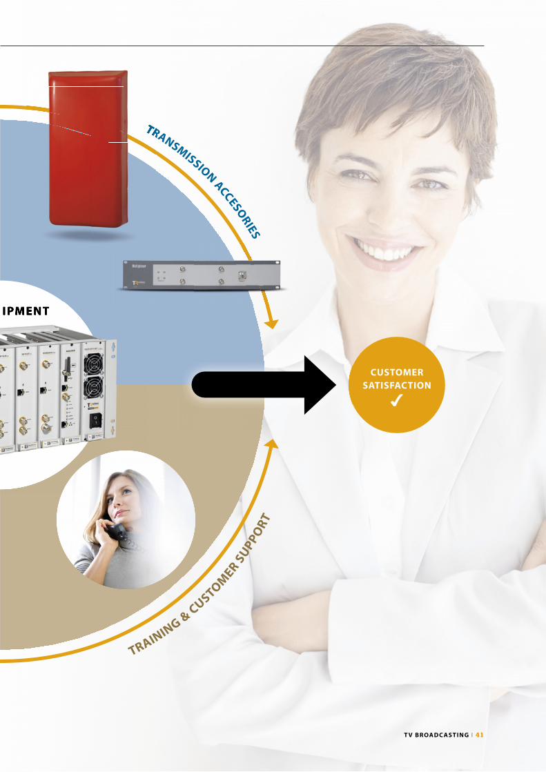
GLOBAL SYSTEMSOLUTION
TRedess offers more than TV broadcast equipment. Our aim is to deliver a global system solution to cover our customer needs.
Plug&Play solutions. TRedess equipment and systems are built, confi gured and adjusted in our factory according to the specifi c requirements of our customers, so the delivered solution is ready to be used. Technical Advice and Support.We work closely with customers to ensure they get the maximum benefi t of our systems, so we provide advice in system confi guration, training and technical support.
Integration of 3rd party equipment. TRedess integrates 3rd party devices with our systems if required.
Flexibility. Our equipment and systems are fl exible to adapt the solution to the customer needs.
CABIN
ETS & INTEGRATION
TRANSMISSION ACCESORIES
TRAINING &
CUSTOMER S
UPPO
RT
RECEPTION A
CCESORIES
T X. EQU IPMENT
CUSTOMER NEEDS
S&
IN
T X. EQU IPMENT
T V BROADC ASTING I 41
CABIN
ETS & INTEGRATION
TRANSMISSION ACCESORIES
TRAINING &
CUSTOMER S
UPPO
RT
RECEPTION A
CCESORIESTR
T X. EQU IPMENT
CUSTOMERSATISFACTION
✔
T X. EQU IPMENT

42 I TREDESS
INTEGRATED SOLUTIONS ACCESORIES
COFDM-ASI CONVERTER FOR BROADCAST SERIES ACTIVE DEMULTIPLEXER
Reference 858120
Denomination MOD ACTIVE DEMUX
Frequency range 470 – 862 MHz
Impedance 50 Ohm
Inputs 1
Outputs 8
Gain margin (per output) 9.5 +/- 1 dB
Band oscillation < 1.5 dB
Attenuation @ 100 MHz > 65 dB
Attenuation @ 950 MHz > 20 dB
Noise fi gure < 5 dB
IP3 output +20 dBm
Input return losses > 13 dB (15 dB typ)
Output return losses >18 dB
Outputs isolation >25dB
Input connector BNC
Output connector BNC
Power supply 13.5V / 110mA (two inputs)
Reference 858131
Denomination MOD COFDM-ASI
Frequency range 470 - 862MHz
Noise Figure ≤6dB
Frequency image rejection ≥65dB
Lock margin ±500KHz
Input signal range(64QAM, 2/3, 1/4, 8MHz)
-80dBm to -10dBm
Bandwidth 6MHz, 7MHz, 8MHz
Constelation QPSK, 16 QAM, 64 QAM
FFT 2K, 8K
Guard interval 1/4, 1/8, 1/16, 1/32
FEC 1/2, 2/3, 3/4, 5/6, 7/8
Standard ETS300744
Decoder MPEG-2 input format
TSMPEG-2/DVB
RF input impedance 50Ω
RF input connector BNC female
MPEG-2 output ASI
ASI modes Byte, Packet
MPEG-2 output connector BNC female
MPEG-2 output impedance 75Ω
Comsumption 5V : 550mA
Working temperature 0 to 45ºC
Dimensions 45x218(5HU)x152mm
Weight 0,7Kg
MULTIPLEXER FILTERS
ACCESORIES FOR THE BROADCASTING EQUIPMENT
INTE
GR
ATE
D S
OLU
TIO
NS
E
References 858507 858508 858509 858510 858511 858512
Denomination MONOPLEXER DIPLEXER TRIPLEXER TETRAPLEXER DOUBLE DIPLEXER PENTAPLEXER
Frequency range 470 - 862 MHz
Inpedance 50 Ohm
Number of resonants 3
Input/output return losses > 20 dB
Bandwidth 1 TV Channel (CCIR 8 MHz)
Insertion losses 1 dB
Maximum input power 10 W DVB-T / 50 W analog
Channel N±3 rejection > 30 dB
Number of Inputs 1 2 3 4 4 5
Input connectors BNC Female
Output connector Type N Female
Size 19” x 2HU x 250mm 19” x 3HU x 250mm

T V BROADC ASTING I 43
TRANSMISSION PANELS
POWER DISTRIBUTORS
RECEPTION ANTENNAS
Reference 857025 857031
Denomination PANEL PH PANEL PV
Gain 13 dBi
Bandwith 470 - 862 MHz
Front-to-back ratio > 18 dB
Impedance 50 Ω
VSWR < 1.1 : 1
Max. input power 400 W (N conn.) · 1000 W (DIN 7/16 conn.)
Polarization Horizontal Vertical
H Beamwidth 60º
V Beamwidth 26º
Wind speed 180 km/h
Wind load 1000 N (front) · 350 N (side)
Materials Dipoles in aluminium · Radome in fi ber glass
Temperature -40ºC to +70ºC
Dimensions 990 x 490 x 190 mm
Weight 12 kg
Connector N Female or DIN 7/16 Female
References 857027 857028 857029
Denomination DIST-2OUT DIST-3OUT DIST-4OUT
Number of outputs 2 3 4
Bandwith 470 - 862 MHz
Insertion loss < 0,05 dB
Impedance 50 Ω
VSWR < 1.1 : 1 dB Broadband
Power 1 kW
Materials Silver brass, copper and stainless steel
Typical Length 850 mm
Input connector DIN 7/16 Female
Output connector DIN 7/16 Female
Denomination YAGI
Gain 17 dBi
Bandwith 470 - 862 MHz
Front to Back Ratio ≥ 25 dB
Impedance 50 Ω
VSWR < 1.5 : 1 dB
Power 100 W
Polarization Linear (Horizontal or Vertical)
H Beamwidth 30º
V Beamwidth 30º
Wind Speed 200 km/h
Wind load 800 N (front) · 1100 N (side)
MaterialsDipoles in aluminiumRadome in polyester
Dimensions 2000 x 565 x 495 mm
Weight 7 kg
Connector N Female
Reference Frequency (MHz)
857011 470 - 566
857012 566 - 654
857013 654 - 734
857014 734 - 862
INTE
GR
ATE
D S
OLU
TIO
NS
E

44 I TREDESS
INTEGRATED SOLUTIONS CABINETS
INDOOR CABINETS
INTE
GR
ATE
D S
OLU
TIO
NS
E
T V BROADC ASTING I 45
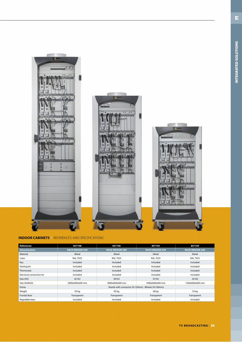
INDOOR CABINETS I REFERENCES AND SPECIFICATIONS
References 857108 857106 857105 857104
Denomination RACK INDOOR 42H RACK INDOOR 38H RACK INDOOR 33H RACK INDOOR 24H
Material Metal Metal Metal Metal
Color RAL 7035 RAL 7035 RAL 7035 RAL 7035
Key Included Included Included Included
Venting kit Included Included Included Included
Thermostat Included Included Included Included
Electrical connection kit Included Included Included Included
Size (HU) 42 HU 38 HU 33 HU 24 HU
Size (HxWxD) 2000x600x600 mm 1800x600x600 mm 1600x600x600 mm 1200x600x600 mm
Extras Nozzle with connector (H:120mm) · Wheels (H:100mm)
Weight 93 kg 83 kg 68 kg 54 kg
Frontal door Transparent Transparent Transparent Transparent
Regulable base Included Included Included Included
INTE
GR
ATE
D S
OLU
TIO
NS
E

46 I TREDESS
INTEGRATED SOLUTIONS CABINETS
INTE
GR
ATE
D S
OLU
TIO
NS
E
T V BROADC ASTING I 47
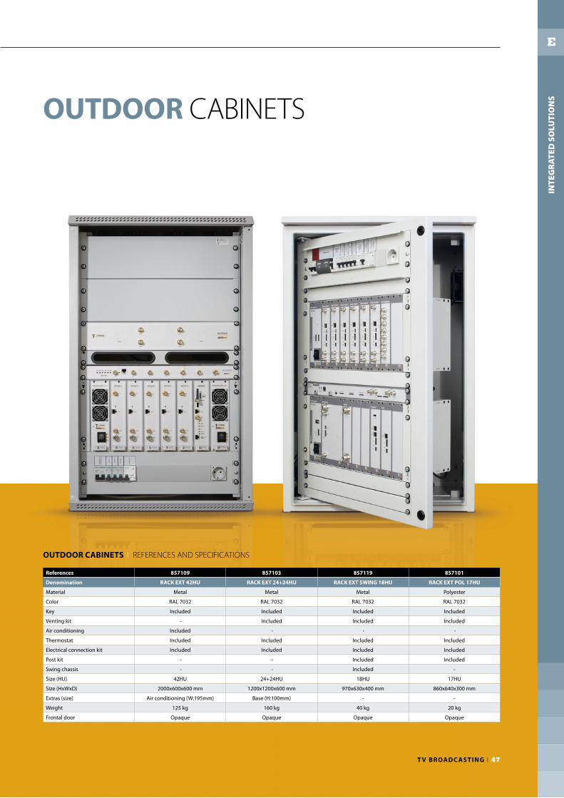
OUTDOOR CABINETS
OUTDOOR CABINETS I REFERENCES AND SPECIFICATIONSIN
TEG
RA
TED
SO
LUTI
ON
S
E
References 857109 857103 857119 857101
Denomination RACK EXT 42HU RACK EXT 24+24HU RACK EXT SWING 18HU RACK EXT POL 17HU
Material Metal Metal Metal Polyester
Color RAL 7032 RAL 7032 RAL 7032 RAL 7032
Key Included Included Included Included
Venting kit - Included Included Included
Air conditioning Included - - -
Thermostat Included Included Included Included
Electrical connection kit Included Included Included Included
Post kit - - Included Included
Swing chassis - - Included -
Size (HU) 42HU 24+24HU 18HU 17HU
Size (HxWxD) 2000x600x600 mm 1200x1200x600 mm 970x630x400 mm 860x640x300 mm
Extras (size) Air conditioning (W:195mm) Base (H:100mm) - -
Weight 125 kg 160 kg 40 kg 20 kg
Frontal door Opaque Opaque Opaque Opaque


EQUIPMENT AND SYSTEMS FORDIGITAL TV BROADCASTING
TRedess 2010, S.L.Volta do Castro, s/n15706 Santiago de CompostelaS P A I N
GPS N: 42° 51’ 52.93”, W: 8° 34’ 5.19”T +34 981 534 203F +34 981 522 [email protected]
TRedess is certifi ed byUNE - EN ISO 9001:2008
06010002 v0514 – Specifi cations are subject to change without notice.