GANA & TOYOBO VOC Recovery and Incinerator
65
Presentation about GANA & TOYOBO VOC Recovery and Incinerator 1
Transcript of GANA & TOYOBO VOC Recovery and Incinerator

Presentation
about
GANA & TOYOBO
VOC Recovery and Incinerator
1

Presentation
about
GANA
2

Comtents
About Us01
VOC Environmental Equipment Types and Scope02
K-FILTER VOC Recovery Device – Steam Removable03
K-FILTER VOC Recovery Device –
Nitrogen Desorption Type04
Zeolite Honey Rotor VOC
Concentration and Combustion Device05
K-MATROLL VOC Deodorization Device06
3

1. Company overview and Division Introduction
2. Company history and company registration status
3. Registration and Certificate
4. Patent
5. Citation
6. Company view
7. Organization chart
About Us011
4

Business name : Gana Public Corporation
Representative Director : Young-Dan Kwak
Business type : manufacturing and construction
Category: Environmental equipment, steel structure, mechanical equipment
Call : 052-239-0566 FAX : 052-239-0565
E - mail : [email protected] Homepage : www.ganaeng.co.kr
1. Company overview and division introduction
※ Address of headquarters / 50-6, Yongyeon-gil, Seosaeng-myeon, Ulju-gun, Ulsan
- Headquarter area: Land 24,750㎡ (7,500 pyeong) /
Factory building 2,470㎡ (750 pyeong), Office building 726㎡, (220 pyeong)
5

- Machine / piping installation and insulation work
- Pressure vessel manufacturing and installation
- Pumping system installation and commissioning
- Made with siro
- Flare Stack production and installation
- Flare Stack production and installation
- Mechanical Equipment Modification
- Over Bridge production and
installation
- Pipe Rack production and
installation
- LNG TANK steel structure
construction
- Steel structure work for various
plants
- VOC exhaust gas adsorption recovery device
- VOC exhaust gas concentration recovery device
- VOC exhaust gas concentrated combustion device
- VOC wastewater treatment unit
- Adsorption carbon fiber method
(Japanese TOYOBO patent)
- Applicable industries: oil refining,
petrochemicals, pharmaceuticals Steel
making, semiconductor, food, etc.
6
1. Company overview and division introduction

2014. 09. Established Gana Public Corporation (corporate business) (capital 500 million won, CEO Young-dan Kwak)
2015. 05. Factory purchase / Head office 48, Yongyeon-gil, Seosaeng-myeon, Ulju-gun, Ulsan
2017. 05. Own design program
2017. 07. Obtained steel structure and machine equipment license
2016. 07. Factory extension / Address Sang-dong[Lot: 24,750m2 (7,500 pyeong) Office: 726m2 (220 pyeong) Factory: 2,574m2 (780 pyeong)]
2018. 12. Established a local corporation in Vietnam
2018. 10. Established subsidiary-One Technology Co., Ltd.-Environmental business
2019. 02. Environmental business (waiting.) / Signed a business agreement with TOYOBO & Ghana
2019. 07. China Branch (Beijing POSCO Building)
2020. 08. Acquired a license for environmental construction business
2020. 11. Small and Medium Venture Business Minister Award (Management Award)
2. Company history and company registration status
7

8
2. Company history and company registration status

3. Registration and Certificate
Domestic business
registration certificate
Vietnam local corporation business
registration certificate
9

Steel structure
construction business
Mechanical equipment
construction business
Environmental specialty
construction business
(waiting field)10
3. Registration and Certificate

MAIN-BIZ confirmation Certificate of company
affiliated research instituteRisk assessment certificate
11
3. Registration and Certificate

ISO 9001 ISO 14001 OHSAS 18001
12
3. Registration and Certificate

Volatile organic compounds and
Fine dust collection system
4. Patent
Through oil vapor reduction and
recovery Air pollution and fire
prevention system
Sea pollution capture,
Disaster prevention and reuse system
13
5. Citation
14

6. Company view
Area: Land 24,750㎡ (7,500 pyeong), Factory building 2,470㎡ (750 pyeong), Office building 726㎡ (220 pyeong)
B동 A동 본관동 환경동
15

7. Organization chart
대 표 이 사
환 경 플 랜 트 / PM 영 업 관 리
기 술 개 발
상 무
VOC
흡착식 회수설비
F/STACK
연소설비
품 질부 사 장
시 공제 작
16

1. Classification and Effect of the Device, Scope of Application
2. VOC Treatment Device Lineup & Scope of Application
VOC Environmental Equipment Types and Scope022
17

1. Classification and Effect of the Device, Scope of Application
【 Effect 】
1) Since we import filter elements from TOYOBO and directly produce the entire equipment, Equipment prices can be lowered due to the effect of import substitution.
2) Manufacturing When the gas input in the production process is generated as an air pollutant after use, Cost is reduced by re-collecting and re-inputting it into the production process line. .
3) A differentiated K-FILTER from malicious substances (GAS) that cannot be treated with the facilities currently in use By treatment, it is excellent in preventing air pollution and improving water quality.
4) The space required for equipment installation is small, making it easy to use the site.
【 Coverage 】
Oil refining, petrochemical, food, power plant, steel making, chemical, semiconductor, display,
It is used in a wide range of industries such as pharmaceuticals, painting, printing, and plating.
18
분 류 후 단 처 리 방 식
Adsorption method
Concentration-
Recovery
수증기 탈착식Vapor desorption method
질소 탈착식Nitrogen desorption method
냉각 응축방식Cold condensation method
[Honey Rotor]
Concentration-
Combustion Method
Concentration-
Combustion
촉매연소방식 (CTO)
Catalytic combustion method
직접연소방식 (TO)
Direct combustion method
축열연소방식 (RTO)
Heat storage combustion method

2. VOC Treatment Device Lineup & Scope of Application
【 VOC treatment equipment lineup 】 【 VOC treatment device application range 】
10,000 60,000ppmC
5,000 30,000ppmC
1,000 6,000ppmC
500 3,000ppmC
100 600ppmC
50 300ppmC
10 60ppmC
処理ガス風量(m3/min)
溶剤
濃度
(ppm
)(at
C=
6)
炭素
換算
濃度
10 50 100 500 1000
KフィルターⓇ
VOC回収装置
ハニローターⓇ
VOC濃縮装置
KマットロールⓇ
VOC脱臭装置KマットロールⓇ
VOC濃縮装置
直接燃焼装置
蓄熱燃焼装置
触媒燃焼装置
KフィルターⓇ窒素脱着型
VOC回収装置
HRKR KU
RTO
TB TC
KFKFーNDK-필터ⓇVOC회수장치
허니로터ⓇVOC농축장치
K매트롤ⓇVOC농축장치
K매트롤ⓇVOC탈취장치
Processed gas air volume(㎥/min)
축열연소장치
촉매연소장치직접연소장치
K필터 질소탈착형VOC회수장치
탄소환산농도
So
lve
nt c
on
ce
ntra
tion
주) X Y축의 눈금은 대수(対数)표시입니다.
19
Classification Device name Adsorption materialRemovable
media
Collection
K-FilterⓇ water vapor
detachable VOC recovery
deviceActivated carbon fiber
(K filterⓇ)
Vapor
K-filterⓇ nitrogen desorption
type VOC recovery deviceNitrogen
Concentration
+
Combustion
Honey rotorⓇ VOC
concentration + RTO
Activated carbon
honeycomb Zeolite
Honeycomb
Air
Concentration
+
Catalytic
combustion
K-matrol® VOC deodorization
device
Activated carbon fiber
(K filterⓇ)Air

1. Operating Principle, Features, Usage, Advantages and Effects
2. What is Activated Carbon Fiber K-FILTER?
3. VOC Treatment Performance by Industry
4. Schematic Diagram of VOC Recovery Device
5. Photo of Installation of Recovery Device After Steam Desorption
6. Standard Specifications and Device Model
7. VOC Recovery System-Cases and Analysis
8. VOC (AN) TANK Recovery Device
9. Comparison of Japanese TOYOBO Facilities and other Companies
10. Target of K-Filter Application
K-FILTER VOC Recovery Device [ Steam Removable]
20
023

1. Operating Principle, Features, Usage, Advantages and Effects
- VOC exhaust gas generated from the production line enters the device by a blower
- It passes through a square-shaped pre-filter and moves to the open filter tube by an
open/closed cylinder.
- At this time, the open filter filters the exhaust gas and releases clean air.
- In the closed tank on the other side, in order to remove the contaminated filter
while in use. The outline is closed and steam is sent through the line into the filter
to pulse the gas on the filter from inside to outside.
21
This device recovers and separates contaminated gas generated from the production
line, It allows you to re-enter the production line. This is how this device works.
【 Operating Principles 】
- The filter action to filter out the VOC exhaust gas and the detachment operation to remove the VOC exhaust gas from the filter take
place at the same time, and as the left and right symmetrical opening and closing cylinders are opened and closed, their roles alternate.
(활성 탄소 섬유)
- The gas shaken off the filter is moved to the condensing condenser, and the temperature is lowered by the cooling water.
After that, the gas transferred to the specific gravity separation tank is divided into layers according to the type.
- Among the separated gases, good gases with high purity that can be recovered are sent back to the production line
for reuse, while unusable gases are sent back to the prefilter of the unit and filtered again by the open filter.

1. High VOC removal performance
Since K Filter® with high adsorption efficiency is used, Removal rate
of more than 99% of low-boiling solvents below 40°C (低沸点溶剤)
2. Compact size
Because the desorption rate of K Filter® is fast,
the amount of adsorbent It is also possible to install on the roof.
3. The quality of the recovery solvent is high
Because the carbon purity of K Filter® is high and the desorption
speed is fast, Little decomposition of solvent
4. Safety is high I
t is difficult to heat storage because the adsorbent is in a felt state.
5. Filter replacement cycle
About 3 to 5 years, subject to change depending on the environment.
【 Characteristic 】 【 Usage 】
Petrochemical: Benzene, styrene monomer, perchloroethylene, etc.
Pharmaceuticals: methylene chloride, toluene, etc.
Semiconductor · liquid crystal: IPA, MEA, etc., acetic acid, butyl, etc.
Food, fermentation cleaning: ethanol, trichloroethanol, etc.
【 Advantages and Effects 】
1) Eliminate air pollution with 99% VOC blocking effect
2) Minimize maintenance cost by recovering high quality
raw materials
3) By converting and reusing exhaust gas Contributing to
resource saving and energy saving
4) Minimized installation space due to compact device
5) Easy filter replacement and easy maintenance
22
1. Operating Principle, Features, Usage, Advantages and Effects

2. What is Activated Carbon Fiber K-FILTER- Erament filter made of carbon fiber with activated carbon nonwoven fabric (product developed by TOYOBO, Japan)
Photo Handiwork (細孔) Characteristic
×1,000
Micropore (2nm), which is the adsorption side of VOC, has a hole directly on the fiber surface.
⁰ The outer surface area is large, and the micropores directly open - Adsorption/desorption speed is 10~100 times that of granular activated carbon
⁰ BET surface area is large (~2000 ㎡/g - Large adsorption capacity
⁰ High carbon purity - The recovered VOC is hardly decomposed.
1,000 times magnification
Granular activated carbon
There is a micropore hole in the middle of the micropore (φ50nm~).
Adsorption and desorption properties of tetrachlorethylene
23

3. VOC Treatment Performance by Industry
업 종
처리실적 (일례)
회수 · 제거(탈취)
제 약
화 학
반도체, 액정
식품 · 발효
세정
기타
업 종
화 학
화 학
염화수소 중의 불순물
염화비닐 모노마
대상물질 풍 량
처리조건
농 도 배출농도 제거율
처리성능
토리클로로에틸렌
IPA, MEA, 등
초산 부틸, 등
IPA, 등
IPA, MEA, 등
에탄올
퍼클로로에틸렌
벤젠, 등
스틸렌 모노마
염화메틸렌
톨루엔
대상물질 농 도풍 량 배출농도 제거율
처리성능가스조건
농도는 메탄CH4 수치
24

4. Schematic Diagram of VOC Recovery Device
25

5. Photo of Installation of Recovery Device After Steam Desorption
TYPE – 2UG-12Ethylene Acetate 2,000PPM _ 120㎥/min
26
TYPE – 2UG-8_100㎥/min

6. Standard Specifications and Device Model
※형식에 대해서
엘레멘트 본수
엘레멘트 층고… G형, S형, L형
탱크형상…R:원형
U:사각형
탱크수량
상기의 형식은 일례입니다.
형식 처리풍량 치수 적산중량
표준사양
27

7. VOC Recovery System-Cases and Analysis
【Case_Hanwha】-Existing 200㎥/min supplement device
28

[Filter replacement work in progress]
[ Replaced filter ]
① ② ③
【Case_Hanwha】-GAS ingredient 200㎥/min
29
교체 작업 중7. VOC Recovery System-Cases and Analysis
[Filter replacement work in progress]

【Case_Hyosung】-Hyosung ChCl3 100N㎥/min / Manufacturing process
In-house Manufacturing Process
30
7. VOC Recovery System-Cases and Analysis
In-house Manufacturing Process

Device Top View Transport after production31
【Case_Hyosung】-Hyosung ChCl3 100N㎥/min / Manufacturing and transportation process
7. VOC Recovery System-Cases and Analysis
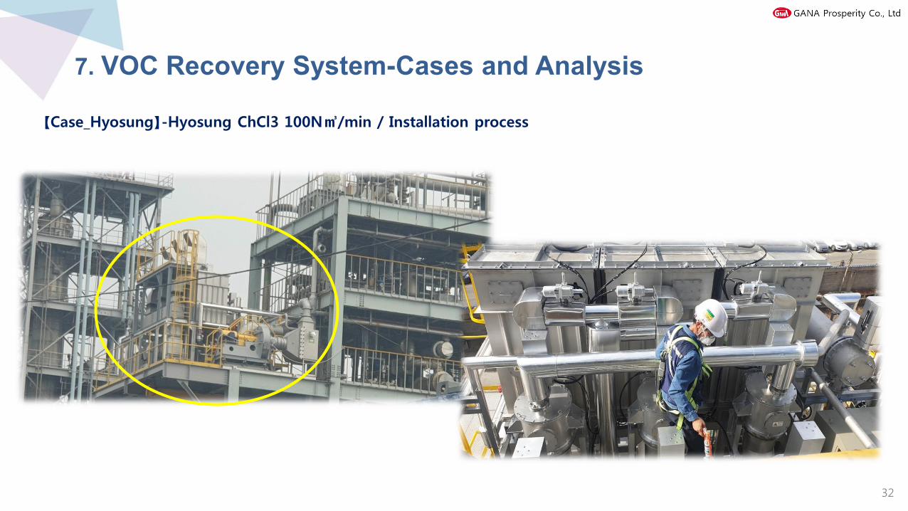
【Case_Hyosung】-Hyosung ChCl3 100N㎥/min / Installation process
32
7. VOC Recovery System-Cases and Analysis

【Case_Hyosung】-Hyosung ChCl3 100N㎥/min / Commissioning process
Commissioning Training
GAS Analysis 33
7. VOC Recovery System-Cases and Analysis

CHCL3 (Separation of Chloroform) AUTOMATIC CONTROL PANEL
34
7. VOC Recovery System-Cases and Analysis
【Case_Hyosung】-Hyosung ChCl3 100N㎥/min / Commissioning process

【Results of Hyosung Aramid ChCl3 (chloroform) analysis】
35
7. VOC Recovery System-Cases and Analysis

8. VOC (AN) TANK Recovery Device
VOC. Schematic diagram of AN recovery device (reservoir or production line)
스팀 사용시
(컨트롤에서 자동제어)
RECOVERY(VOC액체)
36

9. Comparison of Japanese TOYOBO Facilities and other Companies
TOYOBO K-FILTER VOC recovery facility Combustion facility
Recovery after liquefaction of VOCs (reuse or disposal) VOC combustion
In the case of single gas, it is recovered and re-inputted into the process to reduce cost, so the investment cost is recovered
after operation for 3-4 years (based on CHCl3)
It is an incineration facility and cannot be recovered, but The generated energy can be used.
It is automatically operated and the filter replacement cycle is 3 to 5 years, It is easy to replace, and the maintenance cost is
low due to low power and steam.
Electricity and LNG use, replacement, maintenance, etc. Maintenance costs are high due to excessive costs.
The initial investment cost is small. (About 1/4 of combustion facilities)
The initial investment is high.
Due to the small size of the device, it is easy to install even in a narrow space.
Due to the large size of the device, the installation area is large and installation is not easy.
No secondary pollution Secondary pollution NOx+SOx occurs
37

K-Filter 적용대상1,1,1-트리클로로에탄(1,1,1-Trichloroethane)
1,2-다이클로로에테인(1,2-Dichloroethane, Ethylene Dichloride, EDC)
1,4-다이옥산(1,4-Dioxane)
N-니트로소다이메틸아민(N-Nitrosodimethylamine, NDMA, DMN)
N,N-디메틸포름아마이드(N,N-Dimethylmethanamide, DMF)
n-노네인(n-Nonane)
n-데케인(n-Decane)
n-펜테인(n-Pentane)
n-헥세인(n-hexane)
n-헵테인(n-Heptane)
니트로벤젠(Nitrobenzene)
데칼린(Decalin)
디클로로벤젠(O-Dichlorobenzene)
디클로로프로판(1,2-Dichloropropane)
메탄올(Methanol)
메틸 메르캅탄, 메테인 싸이올(Methyl mercaptan, Methane thiol)
메틸 메타 크릴레이트(Methyl Methacrylate, MMA)
메틸이소부틸케톤(Methyl isobuthyl ketone, MIBK)
메틸피롤리돈(1-Methyl-2-Pyrrolidone, NMP)
벤젠(Benzene)
부탄온, 2-부타논, 메틸 에틸 케톤(Methyl Ethyl Ketone, MEK)
사염화탄소(Tetrachloromethane)
스타이렌,스틸렌(Styrene)
시클로헥사논, 아농(Cyclohexanone, Anone)
아세톤(Acetone)
아세트산 뷰틸, 초산 뷰틸(Buthyl Acetate)
아세트산 에틸, 초산 에틸(Ethyl Acetate)
아세트산(Acetic acid)
아이소프로필 알코올(Isopropyl alcohol,IPA)
아크릴로 나이트릴, AN monomer(Acrylonitrile)
암모니아(Ammonia)
에탄(Ethane)
에탄올(Ethanol)
에탄올아민(Monoethanolamin, MEA)
염화메틸렌(Methylene Chloride)
염화비닐(Vinyl chloride)
자일렌, 키실렌(Xylene)
클로로벤젠(Chlorobenzene)
클로로포름(Chloroform, Trichloromethane)
탄화수소 혼합가스
테트라하이드로퓨란(Tetrahydrofuran, THF)
톨루엔(Toluene)
트리메틸벤젠(1,2,4-Trimethylbenzene)
트리클로로에틸렌(Trichloroethylene, TCE)
퍼클로로에틸렌(Perchloroethylene,PCE)
프레온(Freon)
프로필렌 글리콜 메틸 에테르(Propylene glycol methyl ether, PGME)
Target of K-Filter Application
10. Target of K-Filter Application _ Over 1,300 domestic and overseas delivery records
38

1. VOC Recovery Device After Nitrogen Desorption
(Appearance and Circuit Diagram)
2. Standard Specification Table - Nitrogen Desorption Type
VOC Recovery Device-Nitrogen Desorption Type044
39

1. VOC Recovery Device After Nitrogen Desorption (Appearance and Circuit Diagram)
K필터
원가스
원가스FAN
원가스흡착탱크
원가스흡착탱크
콘덴서
회수탱크
쿨러
순환흡착탱크(ND탱크)
제2히터
회수용제
순환FAN제1히터
청정가스
표준 Flow sheet 질소순환라인
A槽 B槽
40

순환송풍기
A탱크 B탱크 ND탱크
Since it is desorptioned as heated nitrogen, there is little separation drainage.
The running cost is low because the nitrogen after use is cleaned up and reused in the ND tank.
It is fixed on the floor, so there is no wear and tear of the absorbent material.
41
1. VOC Recovery Device After Nitrogen Desorption (Appearance and Circuit Diagram)

2. Standard Specification Table - Nitrogen Desorption Type
엘레멘트 사이즈 G:소형, S:중형, L:대형
원가스 흡착 탱크의 엘레멘트 본 수
원가스 흡착 탱크 수
탱크형상 R:원통탱크형, U:사각탱크형
특수 엘레멘트 사용
N2 순환 탈착 방식
형식 예처리풍량 어림중량
치 수
• More than 95% removal rate
• Separation and drainage rate is very small (drainage is 1/10~1/400 of the steam desorption method)
42

1. Principle, Use, Effect
2. Classification of Devices
3. Detailed Structure of Honeycomb Adsorbent
4. Honeycomb Structure Type and Scope of Application
5. Processing Examples and Equipment Features
6. FLOW CHART
7. Coverage and Device Model
8. Installation Appearance
9. Honey Rotor Application Target
Zeolite Honey Rotor [VOC Concentrator]055
43

1. Principle (Catalyst + Combustion)
- Looking at the operation of this unit, when unusable gas is sucked into the
machine through a blower, it reaches the pre-filter.
- This filter filters out large and small particles of dust and impurities from the
gas and also removes moisture.
- Then, the gas moves to the honey filter, and the honey filter is a donut-shaped
filter device in which a honeycomb-shaped adsorbent is surrounded in a
cylindrical shape, and the filter part is surrounded in a circle with the outside.
44
Honey Rotor / catalyst
This device is a zeolite honey rotor device that can effectively save energy.
It recovers and separates contaminated gas generated in the production
line, and then re-injects usable gas into the production line or incinerates it.
표준 Flow sheet
원가스
외기
송풍기 Pre 필터
청정공기
허니로터
청정공기
탈착용열교환기
예열용열교환기
탈착송풍기
Pre 필터
외기
버너
연소로
연소송풍기역화방지기
탈착용
가열공기
농축가스
※온도는 예시입니다.
농축가스
원가스
청정공기 청정공기
HR제거율 97%B제거율 97%
실증 DataHR=농축장치B=직연장치
- The concentrated gas that has fallen from the filter by heat is transferred to the heat exchanger for preheating by the combustion blower.
At this time, a backfire arrester is installed in front of the combustion blower, which prevents fire from entering in the reverse direction.
- The cylindrical filter assembled with this block slowly rotates two or three turns per minute to filter incoming gas, about 85% of
the filter exhausts clean air, and the remaining 15% of the filter removes the gas that was buried with hot air. It.

45
- The heat exchanger for preheating is made up of tightly connected tubes and
the gas is heated by the heat flowing through the tubes.
- The gas, which had a temperature of 180 degrees before passing through the
preheating heat exchanger, passes through the heat exchanger and rises to
400 degrees and is burned in the combustion furnace operated by the burner.
- This process is significantly more efficient than other combustion methods,
reducing the fuel required for combustion.
- This is because it has already changed from low concentration to high
concentration when it is desorbed from the honey rotor, and this itself
becomes an alternative fuel to burn instead of fuel.
Honey Rotor / Combustion Method
1. Principle (Catalyst + Combustion)
표준 Flow sheet
원가스
외기
송풍기 Pre 필터
청정공기
허니로터
청정공기
탈착용열교환기
예열용열교환기
탈착송풍기
Pre 필터
외기
버너
연소로
연소송풍기역화방지기
탈착용
가열공기
농축가스
※온도는 예시입니다.
농축가스
원가스
청정공기 청정공기
HR제거율 97%B제거율 97%
실증 DataHR=농축장치B=직연장치
- The heat generated at this time is 750 degrees Celsius, which heats the heat exchanger to 400 degrees Celsius
and raises the temperature of the gas. In this way, you do not need heat to burn the gas separately.

It uses a honeycomb adsorbent with a high content ratio of activated carbon and zeolite adsorbent manufactured by our own
manufacturing method. High removal rate for multiple VOCs.
Because of the honeycomb structure, the wind speed is 2m/s, so the pressure loss is low even at high speeds, and the power is
okay. High concentration magnification of 20 times or more (concentration magnification = raw gas air volume / desorption gas
air volume) is possible, By miniaturizing the combustion device and recovery device, it is possible to significantly reduce the
running cost. ※ Depending on the conditions, it may not be possible to concentrate more than 20 times.
The cylinder type adopts a lightweight honeycomb block for the honeycomb absorbent, so it is possible to exchange the
absorbent material without the need for heavy equipment.
The honeycomb adsorbent can be reused by regenerating the aged honeycomb adsorbent at our factory. ※ Regeneration may
not be possible depending on the aging condition.
Since 1975, we have delivered more than 1,500 units for various industries and uses, including cutting-edge fields. We will
continue to propose devices optimized for various needs in the future with rich achievements and experiences over 35 years.
[Excellent VOC Removal Performance]
46
1. Principle (Catalyst + Combustion)

Petrochemical: benzene, styrene, ethylene tetrachloride, etc.
Food factory: acetic acid, ethyl, metal ethyl, etc.
Cleaning plant: trichloroethylene, etc.
semiconductor. Liquid crystal: O.P.A, PGME, etc.
Food factory: ethanol, etc.
Painting factory: toluene, xylene, etc.
Pharmaceutical factory: methylene chloride, toluene, etc.
1) Excellent VOC removal
-Maximizing the VOC adsorption area by making high-
performance metal bombs in a honeycomb structure
2) Energy saving driving
-Because of the honeycomb structure, more than 20 times
the concentration ratio is possible with less power.
-Combustion device, recovery device compact possible,
drastically reduced maintenance cost
3) Easy maintenance and repair
-As it is assembled with honeycomb blocks, when
replacing No heavy equipment required
-Filter replacement cycle is every 2~3 years and may
change depending on the environment.
4) Large-capacity odor and particles can be treated at the
same time
【 사용처 】
【 효 과 】1. Use, Effect
47

2. Classification of Devices
48
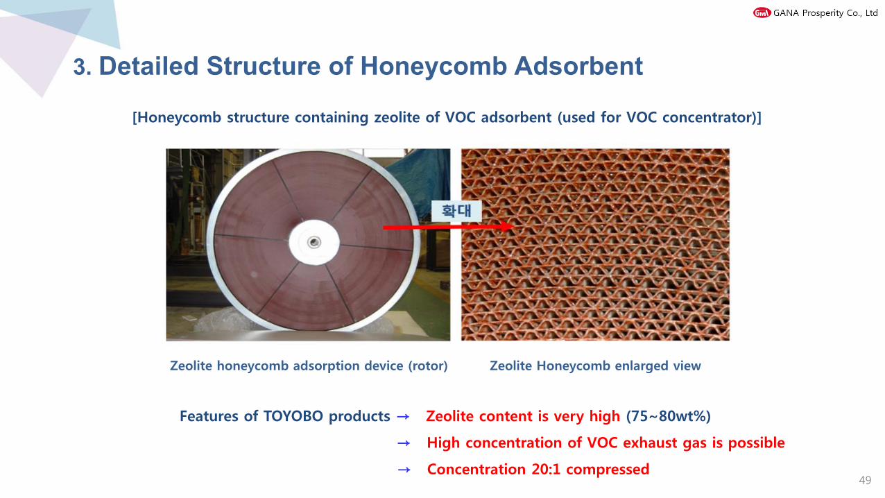
3. Detailed Structure of Honeycomb Adsorbent
[Honeycomb structure containing zeolite of VOC adsorbent (used for VOC concentrator)]
Zeolite honeycomb adsorption device (rotor) Zeolite Honeycomb enlarged view
Features of TOYOBO products → Zeolite content is very high (75~80wt%)
→ High concentration of VOC exhaust gas is possible
→ Concentration 20:1 compressed49

4. Honeycomb Structure Type and Scope of Application
The honeycam on the adsorbent rotates slowly, passing the adsorption zone and desorption zone to
each other to continuously treat VOCs. In the desorption zone, a small amount of heated air is
ventilated to desorb VOCs from the adsorbent honeycam to obtain concentrated gas.
50

5. Processing Examples and Equipment Features
농축원리
벌집흡착재
청정공기
처 리 예
실 적
풍량 원가스농도 처리가스농도농축배율
제거율
톨루엔, 크실렌 외
에탄올 외
초산에틸렌 외
염화메틸렌
트리클로로에틸렌
PGME, PGMEA 외
51

6. FLOW CHART
표준 Flow sheet
원가스
외기
송풍기 Pre 필터
청정공기
허니로터
청정공기
탈착용열교환기
예열용열교환기
탈착송풍기
Pre 필터
외기
버너
연소로
연소송풍기 역화방지기
탈착용
가열공기
농축가스
※온도는 예시입니다.
농축가스
원가스
청정공기 청정공기
HR제거율 97%B제거율 97%
실증 Data HR=농축장치 B=직연장치
52

7. Coverage and Device Model
53

8. Installation Appearance
Heating air generation
MIN/2~3 rotation
85% section
Heating air (15% section)
Original gas Honey Filter
Clean air
VOC desorption
VOC combustion
54
Photo “Honey Rotor®” VOC adsorption concentration device appearance
Thickening device Combustion deviceUtility

Honey rotor Applicable target1,1,1-트리클로로에탄(1,1,1-Trichloroethane)
n-데케인(n-Decane)
데칼린(Decalin)
디메틸아세트아미드(Dimethylacetamide. DMAC)
메탄올(Methanol)
메틸피롤리돈(1-Methyl-2-Pyrrolidone, NMP)
부탄온, 2-부타논, 메틸 에틸 케톤(Methyl Ethyl Ketone, MEK)
스타이렌(Styrene)
아세톤(Acetone)
아세트산 뷰틸(n-Butyl Acetate, NBA)
아세트산(Acetic acid)
아세트산에틸(Ethyl Acetate)
아이소프로필 알코올(Isopropyl alcohol,IPA)
염화 메틸렌(Methylene Chloride)
자일렌(Xylene)
클로로포름(Chloroform, Trichloromethane)
탄화수소 혼합가스
테트라클로로에틸렌(Perchloroethylene, PCE)
테트라하이드로퓨란(Tetrahydrofuran, THF)
톨루엔(Toluene)
트리클로로에틸렌(Trichloroethylene, TCE)
페놀(Phenol)
프로필렌 글리콜 메틸 에테르 아세테이트(PGMEA)
프로필렌 글리콜 메틸 에테르(PGME)
9. Honey Rotor Application Targe_ Over 1,300 domestic and overseas delivery

1. Principle, Use, Effect
2. Device Photo and MATROLL
3. FLOW CHART
4. K-MATROLL Device Model
K-MATROLL [Desorption and combustion device]06
56
6

1. Principle, Use, Effect
【 Principle 】
K-FILTER (Toyobo developed special
Adsorption-type activated carbon fiber
filter) mat is used to adsorb and remove
low-concentrated VOCs.
K-MATROLL rotates slowly in a belt type to
generate heated air Desorption of VOC
through catalyst and oxidizing combustion
through catalyst to remove VOC.
【 Use 】 【 Effect 】
1) Improving the working environment that
harms health
2) Low concentration and small volume
VOC desorption Suitable for processing
3) Application of relatively small-scale local
exhaust treatment (Petrochemical ·
Painting · Printing · Plating ·
Semiconductors and other industries)
1) 100% electric and
separate No utility
required
2) Easy to use ON-OFF type
3) Low maintenance cost
57

2. Device Photo and MATROLL
MATROLL 벨트
It is suitable for deodorizing VOC with low concentration
and picnic volume.
It is effective for working environments that harm your health.
It can be applied to local exhaust treatment of relatively small low concentrations and
excursion volume.
용 도
Original gas
BELT FILTER
VOC Combustion
heated air
Generating heated air
58

3. FLOW CHART
59

4. K-MATROLL Device Model
60

JOHN ZINK HAMWORTHY / RTO
Process description: RISER Derrick Paint

JOHN ZINK HAMWORTHY / RTO
Process description: RISER painted appearance

JOHN ZINK HAMWORTHY / RTO
Process description: Derrick FLAT FORM assembly
Process Description: Derrick Installation Scene
Process description: Derrick assembly
64

THANK YOU
48, Yongyeon-gil, Seosaeng-myeon, Ulju-gun, Ulsan
T. 052-239-0566 / F. 052-239-0565
H. http://ganaeng.co.kr
65


![Gana un libro en pdf[1]](https://static.fdocuments.in/doc/165x107/556317d9d8b42a81528b4f3d/gana-un-libro-en-pdf1.jpg)