
“AUDITORIAS-INSPECCION EN INSTITUTO ASTROFISICA DE CANARIAS”
1LNL, 7 Apr. 2005
L’esperimento di Astrofisica GLAST – ilLarge Area Telescope
GammaGamma--ray Large Area ray Large Area Space TelescopeSpace Telescope
Riccardo Rando
Scuola Nazionale "Rivelatori ed Elettronica per Fisica delleAlte Energie, Astrofisica e Applicazioni Spaziali"
INFN Laboratori Nazionali di Legnaro4-8 Aprile 2005

2LNL, 7 Apr. 2005
Outline
Gamma astrophysics: sources & detection
Tracking telescopesLAT LAT subsystems (ACD,TKR,CAL)GLAST Trigger and Data AcquisitionStatus & conclusions

3LNL, 7 Apr. 2005
High Energy Astrophysics• gamma rays: highly penetrating
• γ's are not affected by the galactic magnetic field
• provide insight on the most energetic phenomena in the universe
• interface between cosmology and high-energy particle physics
• investigate the birth and evolution of the Universe
• requirements:
reconstruct energy,direction
timing informations
reject (lots of) background events

4LNL, 7 Apr. 2005
AGN/PSR• AGN: stellar-like engine, beamed emission of energy
• spectra: from radio to gamma
• different models for inner engine (leptonic, hadronic)
• broad energy coverage, sensitivity
• PSR: magnetized rotating neutron stars
• 30 pulsars known at gamma energies
• sensitivity and time response to identify the periodic signal
• different models describe emission of accelerated particles, multiwavelengthanalysis to discriminate by spectral analysis

5LNL, 7 Apr. 2005
GRB/CRs• GRBs: gamma flashes, discovered in 1967
• BATSE measured 2704 GRBs in 9 years, isotropic distribution in the sky
• different spectral characteristics, time structure: 1000 s down to sub-ms features
• model involves the collision of blobs of relativistic matter ejected from a central engine, broad energy coverage and fast time response are required
• CRs: known since 1912, Nobel prize (Hess) in 1936
• unknown origin (yet)
• 89% H, 10% He, 1% all heavier elements
• energies up to 1020 ev ( at 250 km/h!)
• supernovae are candidate sites of CR acceleration
• observations of interactions of CR and ISM near a supernova remnant could settle the issue: resolution

6LNL, 7 Apr. 2005
Detecting Cosmic Gamma Rays• though gamma rays are penetrating, atmospheric integrated density is ~ 1 kg/cm2
• at higher energy (TeV) the whole atmosphere is the detecting medium (Cerenkov, ACT)
• at lower energies: balloons / satellites are required to avoid the atmospheric attenuation

7LNL, 7 Apr. 2005
Instruments• scintillators (CsI, NaI, BGO, ...)
• Cerenkov counters
• collimators (as in X-ray telescopes) are not suitable
• early: active collimation, the active elements define a pointing direction with their arrangement
• currently: trackers (spark chambers, silicon), direction is reconstructed from secondaries
25° deg
OSO3SAS2
8LNL, 7 Apr. 2005
Photons are converted...
Eγθ,φ
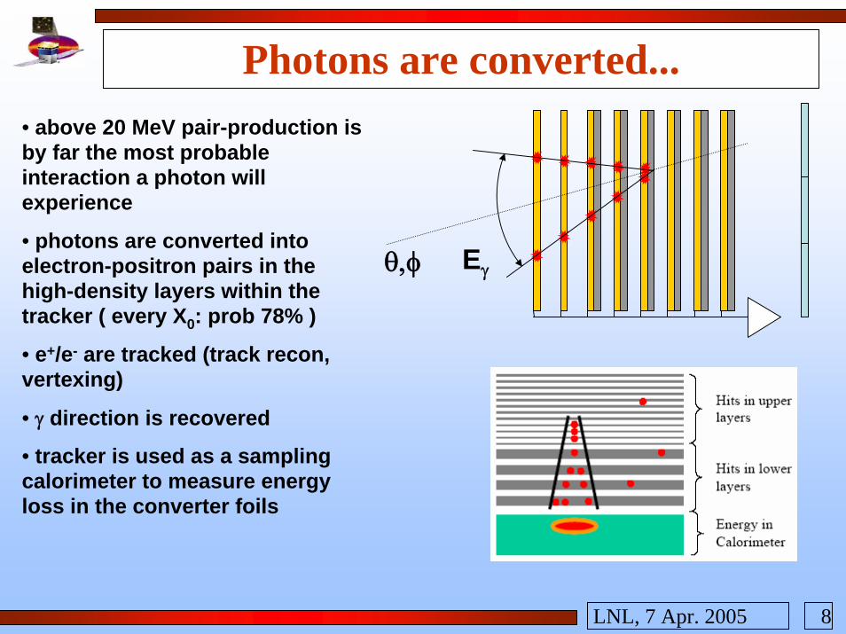
• above 20 MeV pair-production is by far the most probable interaction a photon will experience
• photons are converted into electron-positron pairs in the high-density layers within the tracker ( every X0: prob 78% )
• e+/e- are tracked (track recon, vertexing)
• γ direction is recovered
• tracker is used as a sampling calorimeter to measure energy loss in the converter foils

9LNL, 7 Apr. 2005
...and secondaries are scored
• in the remaining layers the electrons lose energy
• in the calorimeter an EM shower develops
• due to satellite constraints, a lot of energy will be lost! (calorimeter is small, made of non-adjacent blocks)
• complicated energy reconstruction procedures will be required:
CAL ends here
• loss from the back
• loss from the sides
• loss in gaps
• loss in the TKR
10LNL, 7 Apr. 2005
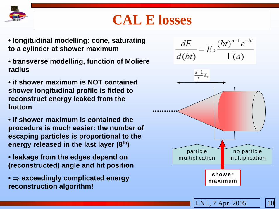
CAL E losses• longitudinal modelling: cone, saturating to a cylinder at shower maximum
• transverse modelling, function of Moliereradius
• if shower maximum is NOT contained shower longitudinal profile is fitted to reconstruct energy leaked from the bottom
• if shower maximum is contained the procedure is much easier: the number of escaping particles is proportional to the energy released in the last layer (8th)
• leakage from the edges depend on (reconstructed) angle and hit position
• ⇒ exceedingly complicated energy reconstruction algorithm!
particlemultiplication
no particlemultiplication
showermaximum

11LNL, 7 Apr. 2005
Last flown: Egret• closely spaced spark chamber for tracking
• widely spaced spark chamber for TOF
• NaI(Tl) calorimeter (7.7 X0)
• plastic anticoincidence dome
• energy resolution ~10%
• angular res. 10° (60 MeV) to 1° (10 GeV)
• problems from backsplash from the CAL: the anticoincidence was too close
• map of the galactic background
• 3EG catalogue, 271 point sources (most blazars, 5 pulsars, 170 still unidentified)

12LNL, 7 Apr. 2005
GLAST• Large Area Telescope: a silicon pair-conversion tracking telescope
• GLAST Burst Monitor: scintillating detectors
• Spacecraft
LAT
GBM
13LNL, 7 Apr. 2005
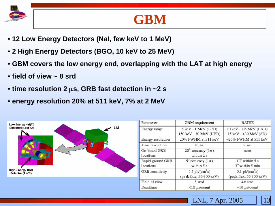
GBM• 12 Low Energy Detectors (NaI, few keV to 1 MeV)
• 2 High Energy Detectors (BGO, 10 keV to 25 MeV)
• GBM covers the low energy end, overlapping with the LAT at high energy
• field of view ~ 8 srd
• time resolution 2 µs, GRB fast detection in ~2 s
• energy resolution 20% at 511 keV, 7% at 2 MeV

14LNL, 7 Apr. 2005
LATTKR
CAL
ACD
Thermalblanket
• silicon tracker, W converter foils
• CsI calorimeter
• plastic ACD
• DAQ electronics
• modular design
• 4 towers, each with TKR, CAL
• segmented ACD

15LNL, 7 Apr. 2005
Science drivers on designγ
e+ e–Energy range and energy resolution requirements bound the thickness and layout of calorimeter
Effective area and PSFrequirements drive the converter thickness and layout. PSF requirements also drive the sensor performance, layer spacing, and the design of the mechanical supports.
Field of view sets the aspect ratio (height/width)
Time accuracy provided by electronics and intrinsic resolution of the sensors.
Electronics
Background rejection requirements drive the ACD design (and influence the calorimeter and tracker layouts).
On-board transient detectionrequirements, and on-board background rejection to meet telemetry requirements are relevant to the electronics, processing, flight software, and trigger design.
Instrument life has an impact on detector technology choices (NO CONSUMABLES).Derived requirements (source location determination and point source sensitivity) are a result of the overall system performance.
TKRTKR
CAL CAL
FRONT 3 %XoBACK 18 % XoPITCH 228 µm
8.5 XoHODOSCOPIC, GRANULAR
0,9997 EFFICIENCYSEGMENTED,REDUNDANT
NO DEAD _TIME FROM SILICON SENSORS
TRACKER
CAL
ACD
From: L. Latronico, ICATPP03

16LNL, 7 Apr. 2005
AntiCoincidence Detector• tiles of plastic scintillator, wavelength shifting fibers, photomultiplier tubes
• light-tight case for each tile to limit impact of micrometeorite damage
• power < 31 W
• reject charged particles (105 more than γ's)
• low energy photons from CAL (0.2÷2 MeV) give Compton signal comparable to a MIP
• 50% less Aeff in EGRET!! ( at 10 GeV, with respect to 1 GeV )
• segmentation can associate this events to CAL backsplash and avoid self-vetoing (to less than 20% of “dangerous” events)

17LNL, 7 Apr. 2005
Tracker
• electronic modules tested at INFN Pi, assembles on two sides of tray (top/bottom)
• each tray is stacked on the others, rotated by 90 degrees
• a tower is composed by 19 trays, 12 with a thin W foil (0.03 X0), 4 with a thick foil (0.18 X0) and 3 w/o converter

18LNL, 7 Apr. 2005
Silicon detectors• Hamamatsu: qualified producer for HEP experiments
• 11,500 SSD delivered (10,368 for assembly [83 m2] + spares + wastage + prototypes)
• 885,000 channels!!!
• tested at HPK
• quality is so high that no search for bad strips is needed: only sum current is checked
• rejection rate at INFN lower than 0.6%
• after ladder assembly: loss rate ~2% (1% for mishandling), 0.03% bad strips

19LNL, 7 Apr. 2005
TKR electronics• 1536 channels per tower plane: 24 FE ASICs with 64 strips each
• 2 Readout Controllers, one on each side, manage communications
• GTFE pads bonded to a pitch adapter and to the silicon sensors
• GTRC connected with a flex cable to the DAQ cable controllers on the Tower Electronics Module, below TKR
• registers hardened against SEU (Rockett, 1988)
• ASICs hardened against SEL (thin epi-layer)
• tests with heavy ions, gamma rays
SEU cross sections
unhardenedhardened

20LNL, 7 Apr. 2005
GTFE structure• low power cascode amplifier, 37 mV per MIP
• RC-CR shaper, 1.5 µs
• single-threshold comparator
• a calibration capacitor allows for charge injection for testing
• all channels in a GTFE are OR-ed, OR is propagated to other GTFEs to generate a fast trigger request for an entire layer
• pulse height is not measured: it can be obtained measuring time-over-threshold
• low power (<250 µW per channel)
• low noise occupancy (<10-4 ch/trg)
• complete zero-suppression

21LNL, 7 Apr. 2005
TKR assembly
22LNL, 7 Apr. 2005
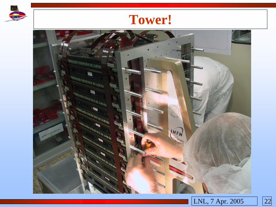
Tower!

23LNL, 7 Apr. 2005
Integration• INFN Pisa receives TKR flight parts
• MCMs are tested, before and after being assembled in a TKR tray
• complete trays are tested
• trays are assembled in a stack configuration and a self-triggering data acquisition is performed
• flight trays are assembled into a tower!
24LNL, 7 Apr. 2005
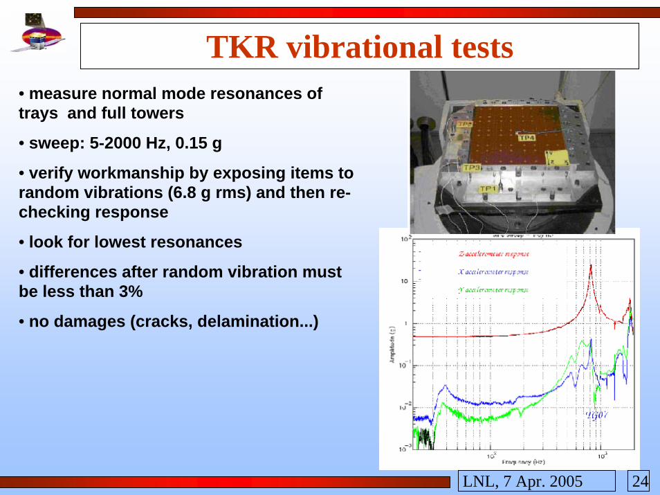
TKR vibrational tests• measure normal mode resonances of trays and full towers
• sweep: 5-2000 Hz, 0.15 g
• verify workmanship by exposing items to random vibrations (6.8 g rms) and then re-checking response
• look for lowest resonances
• differences after random vibration must be less than 3%
• no damages (cracks, delamination...)

25LNL, 7 Apr. 2005
Stack test

26LNL, 7 Apr. 2005
TKR thermo-vacuum tests• trays must withstand the thermal gradients with no loss in functional properties: test addressing, data taking, noise,....
• T from -30°C to +55°C
• change rate ±40°C/hr, 2.5 hrs at the extremes
• trays are tested in N atmosphere in an environmental chamber
• full towers are tested at the Alenialaboratories
• full “on-ground” DAQ setup
• vacuum: 10-5 torr
• 4 thermal cycles like specified above

27LNL, 7 Apr. 2005
Calorimeter
• hard constraints on mass (payload)
• power budget in the space telescope must be checked carefully
• 16 towers, 8 layers, 12 xtals per layer : 1536 crystals
• weight is 1500 kg, P < 91 W !
• self-triggering

28LNL, 7 Apr. 2005
CsI crystalsThe boule is cut...
... again ... ... and again.
Each crystal is polished... ... then a side is scratched ... ... and it's put in a safe.(tapering)

29LNL, 7 Apr. 2005
CAL assembly• each XTAL: a Dual Diode Package at each side
• two PIN diodes: low/high energies, depending on the area
• XTAL wrapped in VM2000 reflective foil (2× increase in light collection)
• flex cables added, positioned in tray
• connected to electronics (FE)
• added TEM and connected

30LNL, 7 Apr. 2005
CAL electronics
12 bit, successive approssimationCOTS as fast ADCdead time<20µs
Low energy range: 2÷800 MeVHigh energy range: 100 MeV ÷ 100 GeV
94mm2
24mm2

31LNL, 7 Apr. 2005
CAL calibration & test
• 511 kev 22Na source used as light source• yield: >5000 e/MeV to be accepted
• beam test: muons750 e/MeV from small diode3000 e/MeV from large diode
• light tapering allows position reconstruction along crystal• tapering: ~40% loss across XTAL length
position recon:RMS ~ 0.28cm

32LNL, 7 Apr. 2005
DAQ system• triggers the LAT, read out events, process them into the downlink stream.
• GLAST Global Trigger receives signals from the LAT electronics and creates trigger primitives: 3-in-a-row in the TKR (= 6-fold coincidence), ACD tile above threshold,...
• primitives are processed into high-level named primitives (“3-in-a-row with CAL-HI”,...) used for L1T
• L1T: tower level, rate is 6 kHz (peak: 9 kHz)
• L2T: still tower level, loose cuts on background, 1 kHz (peak: 2 kHz)
• L3T: full instrument-wide reconstruction, should drop to 15 Hz
• OK for telemetry, but a significant background rejection still needs to be done on ground
AC
D-L
OW
3-in
-a-r
owC
AL-
HI

33LNL, 7 Apr. 2005
Status• TKR towers being assembled at the INFN labs in Pisa
• tests (DAQ, vibrational, thermo-vacuum)
• towers are sent to SLAC for Integration & Test
• tests with cosmic rays, Van de Graaff gamma's
• tray alignment is checked
• towers (TKR+CAL+DAQ) will be placed in the support grid, LAT assembled

34LNL, 7 Apr. 2005
Conclusions
• Astrophysics borrowed detector technology from high energy physics
• Si microstrip tracker, CsI EM calorimeter
• INFN: expertise in the field: design, assembly, test...
• Key aspects of LAT assembly are entrusted to industrial partners (quality control and certification, insurances, overtime fees, ...)
• Production has reached the stage of subsystem integration
• Test results validated key aspects of detector design
• Novel problems were encountered and solved
• Focus shifts on data analysis and science issues

35LNL, 7 Apr. 2005
Some spare slides...

36LNL, 7 Apr. 2005
TKR digital ASICs• GTRC interfaces GTFEs and TEM
• The layer ID is set by 4 pads, it's hardcoded in the flex cable
• 2 registers regulate the operations:➢ REG: see right! 22 bits to store configuration, 6 error bits, 5 enable, 1 readonly
➢ SYNC: 8 bit, controls synchronization in communications with GTFEs• Only the “CONF” 22 bits and the SYNC affect the ASIC functionalities
• 2 buffers to download data frames and store them
• TOT counter: time over threshold is ~ proportional to the injected charge
37LNL, 7 Apr. 2005
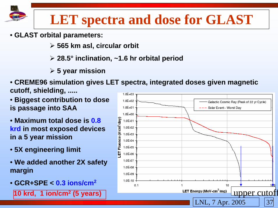
LET spectra and dose for GLAST• GLAST orbital parameters:
565 km asl, circular orbit
28.5° inclination, ~1.6 hr orbital period
5 year mission• CREME96 simulation gives LET spectra, integrated doses given magnetic cutoff, shielding, .....• Biggest contribution to dose is passage into SAA
• Maximum total dose is 0.8 krd in most exposed devices in a 5 year mission
• 5X engineering limit
• We added another 2X safety margin
• GCR+SPE < 0.3 ions/cm2
10 krd, 1 ion/cm2 (5 years) upper cutoff

38LNL, 7 Apr. 2005
P5 P2
Rockett cell

39LNL, 7 Apr. 2005
Background• γ / background events ratio is ~ 1:105
• A rejection factor ~100 should be obtained on-board after L3T and OnboardFilter
• Another factor ~100 is required on ground to prepare dataset for science analysis
• This requirement was demonstrated with the tools available at the time of the AO / Flight Inv.
• Being carried on with the official LAT Software
• Standard path: investigate useful cuts on highly-discriminating variables:

40LNL, 7 Apr. 2005
Background rejection• Current implementation uses regression trees, approach taken from soft sciences
• A training (simulated) data set is used to grow a predictor, recursively partitioning the data in categories (signal/noise, good/bad, ...) with cuts on the variables they contain in an automated way
• The predictor can then be applied to other data to classify them


![Destructive single-event effects in semiconductor devices ...sirad.pd.infn.it/~candelor/Parte6/TNS2003_SEB_SEGR_OKPerCorso.pdf · [17]). Other researchers quickly confirmed the existence](https://static.fdocuments.in/doc/165x107/5f6a24f7cd3d3344cb52e064/destructive-single-event-effects-in-semiconductor-devices-siradpdinfnitcandelorparte6tns2003sebsegr.jpg)


