Gambit Tips and Tricks
75
1 / 75 Gambit 2.2 Tips & Tricks Thomas Scheidegger June 8, 2004
-
Upload
muralidharan-shanmugam -
Category
Documents
-
view
313 -
download
5
description
Gambit Tips and Tricks
Transcript of Gambit Tips and Tricks

1 / 75
Gambit 2.2 Tips & TricksThomas Scheidegger
June 8, 2004

2 / 75
Outline
• Data exchange with other CAD systems• Construction and clean-up tools• Meshing tools• Miscellaneous tips and tricks

3 / 75
Data exchange with other CAD Systems
• CAD data import• Checking connectivity• Checking real geometry/topology• Tolerant modeling• Healing and smoothing real geometry• Data exchange via mesh import

4 / 75
Geometry (Real/Virtual)
CAD Data Import
Geometry Mesh Faceted Geometry
•ACIS (R12)
•Parasolid (v15.0)
•Catia V4
•STEP (AP203/214)
•IGES
•Direct Pro/E Interface
•I-DEAS FTL
•STL
•VRML
•Optegra visualizer
•I-DEAS UNV
•FLUENT/TGRID
•CGNS (v2.0)
•PLOT3D (formatted)
•ANSYS
•PATRAN
•NASTRAN
Geometry (Faceted)
Geometry (Faceted)
New InterOP R12 translators for IGES, STEP, Parasolid, and Catia 4 (add-on) in Gambit 2.2– Warning is issued if the model size exceeds 10000 units

5 / 75
Checking Connectivity
• Check import of volumes/faces using entity based coloring– Vertices (white), edges (yellow), faces (light blue), volumes (green),
groups (dark green)– Virtual/faceted geometry identified by label (v_*/f_*), picking filter,
and color coding• Vertices (darkkhaki), edges (peru), faces (dodgerblue),
volumes (springgreen)
• Check connectivity using connectivity based coloring– White: Stand-alone vertex or edge– Orange: Vertex connected to only one edge, or edge connected to
only one face (i.e. unconnected face!)– Blue: Vertex connected to exactly two edges, or edge connected to
exactly two faces (i.e. connected face)– Magenta: Vertex connected to three or more edges, or edge
connected to three or more faces (e.g. internal face)

6 / 75
Checking Connectivity
Color by entity Color by connectivity

7 / 75
Checking Real Geometry/Topology
• Checks for geometrical and topological inconsistencies– Topology problems (very rare) must be fixed before meshing– Detailed reporting through change in defaults
• GEOMETRY.GENERAL.REAL_GEOMETRY_CHECK_SUMMARY = 0– Geometry not C1 or G1
• Indicates lack of parametric/geometric continuity• Real operations (booleans, splits, sweeps) may fail• Can use virtual operations as fallback• Geometry errors do generally not prevent meshing. If the model can be
shaded, then it can likely be meshed
• How to fix problems– Fix real geometry problems by healing the unconnected entities,
smoothing (new in Gambit 2.2), or by regenerating entities– Fix topology problems by deleting and reconstructing entities– Fix virtual/faceted geometry problems by deleting (hiding) and
reconstructing entities

8 / 75
Tolerant Modeling
• Tolerant modeling in Gambit– Real connectivity using an automatically evaluated local
tolerance value (instead of 1.0e-6 real ACIS tolerance) assigned to vertices and edges
– Allows use of less precise CAD data and still ensures proper topology
– Most construction tools (Booleans and splits) are tolerant– Requires less virtual clean-up– Tolerant modeling will attempt to stitch volume– Make geometry tolerant
• globally during geometry import– all entities can be connected– Automatic sliver/short edge removal during tolerant import,
controlled through defaultsGEOMETRY.TOLERANCE.HEAL_REMOVE_SLIVER_FACE = -1GEOMETRY.TOLERANCE.HEAL_REMOVE_SHORT_EDGE = 0.001Print out of entity labels being eliminated
• controlled inside heal face/volume forms– all entities need to be disconnected before making tolerant

9 / 75
• Assigns local tolerances instead of geometry modification• Tolerances based on face size or edge length (body box size).
Stitching stops at maximum tolerance
Body box size Maximum tolerance< 0.01 0.0001< 0.1 0.001< 1.0 0.01< 10.0 0.1> 10.0 1.0
Tolerant Modeling
Tolerant IGES import

10 / 75
Healing Real Geometry
• ACIS is a high precision modeler and needs all entities to satisfy stringent data integrity check
• Geometry imported from other CAD systems often lacks the required accuracy
• Healing is an operation designed to detect and correct accuracy problems in ACIS models
• Optional healing processes– Geometry simplification
• Spline to analytic geometry conversion– Stitch faces– Repair geometry
• Heals inaccuracies in model
• Healing always includes tolerant modeling• Auto or manual tolerances

11 / 75
Healing Real Geometry
Stitch faces Stitch faces, Repair geometry
Effective tool to connect (stitch) faces into a volumeFace healing can result in multiple volumes

12 / 75
Healing Real Geometry
• Heal model– globally during geometry import
• all entities can be connected• no control over heal options
– controlled inside heal face/volume forms• all entities need to be disconnected before healing• manual control over heal options and tolerances• often easier to export ACIS model and heal globally during re-import
• Healing repairs geometry near boundaries. Healing does not fix geometry defects distant from edges
• Healing can further corrupt poor geometry. Carefully inspect andcheck geometry after healing!

13 / 75
Smoothing Real Geometry
• Geometry (edge, face) smoothing in Gambit 2.2– Smoothes discontinuous edges– Reduces geometry discontinuity defects for B-spline surfaces– Can aid in subsequent Boolean operations– Two smoothing options
• Remove discontinuities– Remove G1 discontinuity (default)
• Reduce complexity – Simplified NURB representation
Face smoothing

14 / 75
Data Exchange via Mesh Import
• Import of surface or volume mesh files results in faceted geometry, similar to virtual geometry– Use virtual geometry operations to work with entities– Convert virtual geometry to real if needed
• Effective method to ‘clean’ corrupt meshable geometry– Mesh the defect geometry in Gambit with sufficiently fine spacing– Assign boundary zones to faces as necessary, export mesh– Import mesh back into Gambit and work with faceted geometry
• Boundary types are preserved during import of mesh files into Gambit – Except periodic boundary types, periodic_shadow will have type ‘wall’– Import of mesh with hanging nodes (e.g. adapted mesh, hex core
mesh) is not supported– PLOT 3D files with Iblanking or of binary type need to be converted to
Fluent/Fidap mesh file using utility fe2ram• 64-bit utility available for large mesh files
15 / 75
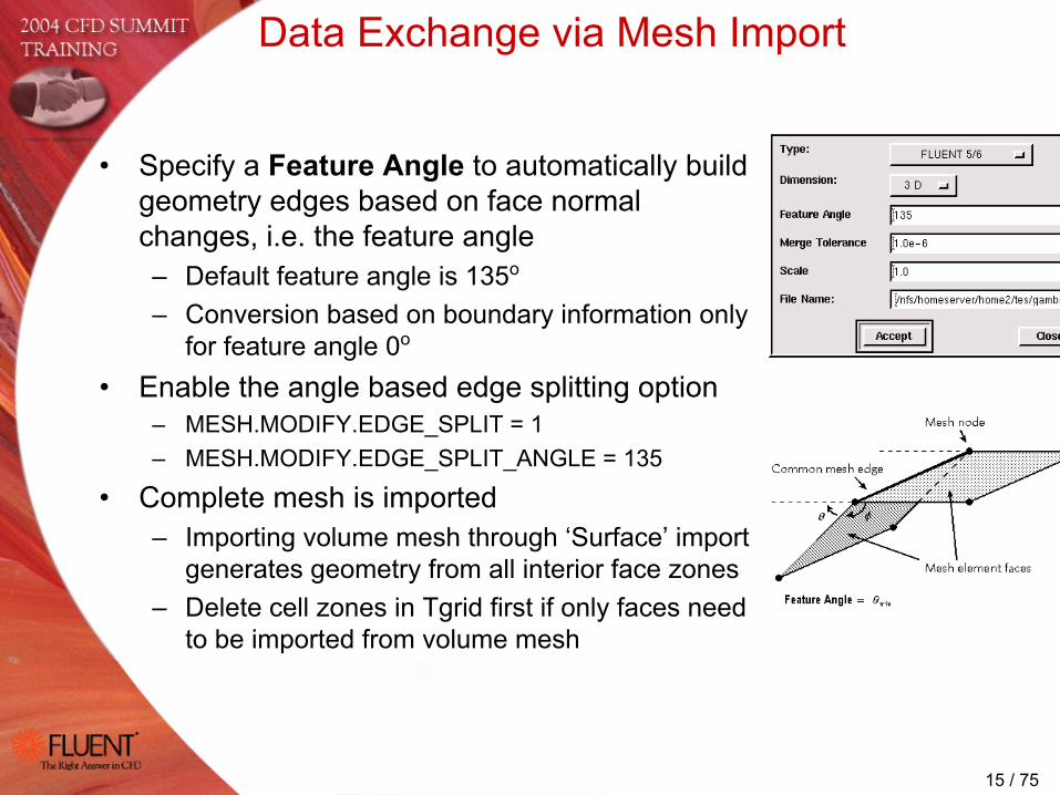
• Specify a Feature Angle to automatically build geometry edges based on face normal changes, i.e. the feature angle– Default feature angle is 135o
– Conversion based on boundary information only for feature angle 0o
• Enable the angle based edge splitting option– MESH.MODIFY.EDGE_SPLIT = 1– MESH.MODIFY.EDGE_SPLIT_ANGLE = 135
• Complete mesh is imported– Importing volume mesh through ‘Surface’ import
generates geometry from all interior face zones– Delete cell zones in Tgrid first if only faces need
to be imported from volume mesh
Data Exchange via Mesh Import

16 / 75
• Adjust imported topology using the mesh modify forms (face/volume)
– Allows to split faces without loss of connected mesh• Modify meshed volume replaces old volume with new one• Modify meshed face adds modified face to original face
– Unclick the ‘Keep original edge’ toggle to remove existing edges
– Use Automatic Angle to add geometry edges• Similar to feature engle during mesh import
– Fine tune geometry edge definition by manually adding or deleting individual mesh edges
• Spurs removed in single pick
Data Exchange via Mesh Import
Automatic angle: 15 deg Automatic angle: 25 degAdditional edges added manually

17 / 75
Construction and Clean-up Tools
• Real (ACIS) geometry tools• Real Boolean operations• Imprinting• Virtual geometry tools• Clean-up tools• Decomposing virtual geometry

18 / 75
Real Face From Wireframe
• Create face from wireframe– Coplanar edges
• Any number of coplanar edges within ACIS tolerance can be stitched into a real face
– Non-coplanar edges• Any 3 or 4 sided non-planar loop can be stitched into real face• Loops with 5 or more non-planar edges can be stitched into real face if
– Edge loop is convex– Edges don’t turn ‘excessively’
– New planar tolerant real face creation in Gambit 2.2 for non-coplanar edge loops
• Tolerant option ignored if ACIS is able to create non-tolerant face• Maximum tolerance reported in transcript window• Edges should be close to coplanar and connected• Tolerance should be smaller than intended mesh size
– Turn off final projection of mesh from facets to geometry if tolerance is larger than mesh size (MESH.FACE.PROJECT_TO_SURFACE = 0)
19 / 75
Real Face From Wireframe
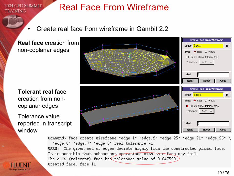
• Create real face from wireframe in Gambit 2.2
Real face creation from non-coplanar edges
Tolerant real facecreation from non-coplanar edges
Tolerance value reported in transcript window

20 / 75
Real Volume Stitch
• Create volume by stitching faces in Gambit 2.2– Real tolerant face stitch with tolerance option
• Automatic or manual tolerance control• Tolerance should be smaller than intended mesh size
– Both real and virtual creation in single step– May produce unwanted short edges
• Healing can be tried in place of stitching• GEOMETRY.VOLUME.SPLIT_AT_CVXTY_PTS_IN_FACE_STITCH = 0
– Option to stitch single or multiple volumes• Automatic addition of missing (connected) faces for single volume• Extra faces automatically discarded for multiple volumes
– Single volume stitch can handle voids and dangling faces in Gambit 2.2

21 / 75
Real Volume Stitch
• Single volume– Searches automatically for missing (connected) faces– Builds smallest possible volume from selected faces
• Multiple volumes– Builds volumes for each watertight set of faces found– Discards extra faces not belonging to a closed set
Three possible volumes 1 2 3

22 / 75
Real Boolean Operations
• Why Boolean operations can fail– Poor geometric quality, complex topology– NURBS surfaces do not represent cylinders and spheres exactly.
Boolean between ‘coincident’ analytic and NURBS surfaces are unpredictable
– Difficulties in finding imprints of connected entities• Two imprinting algorithms available
GEOMETRY.VOLUME.BOOLEAN_METHOD = 0, 1
• What to do if split operation of entity A with B fails– Copy/Heal option
• Copy B (and heal if needed), delete the original B• Perform the split operation, reconnect before meshing
– Intersection/Subtraction option• Intersect A with B while retaining A• Subtract the result (intersection) from A while retaining the tool• Connect before meshing
– Clean geometry through mesh export/import

23 / 75
Imprinting in Boolean Operations
GEOMETRY.VOLUME.BOOLEAN_METHOD = 1• Default algorithm, more stable• Should not require to disconnect geometry
before operation• Requires subsequent bi-directional split
GEOMETRY.VOLUME.BOOLEAN_METHOD = 0
Global imprinting Local imprinting
Unite cylinder with left cube

24 / 75
Virtual Geometry
• ‘Overlay’ technology– Tool of choice to clean-up and simplify imported geometry– Needed when tolerant modeling and healing/smoothing are not
sufficient– Modifies size and shape of boundary surfaces while being
constrained by underlying ‘host’ geometry definition• Represents same geometry but different topology• Can be derived from real, virtual, or faceted geometry
– Limited use for Boolean operations– Semi-automatic virtual clean-up tool available
Three real faces merged into one virtual face

25 / 75
Virtual Geometry Operations
• Merge: Replaces two connected entities (edge/face/volume) with a single virtual entity– Only volumes can be merged in real
• Split: Partitions an individual entity (edge/face/volume) into two or more connected virtual entities
• Connect: Combines two individual unconnected entities (vertex/edge/face) into a single virtual entity– Connect entities by connecting lower order topology– Virtual connect can bridge relatively large gaps in model, larger
than ACIS tolerance of 1.0e-6• Collapse: Splits a face and merges the resulting with two
neighboring faces• Simplify Faces: Removes dangling edges
26 / 75
Semi-automatic Clean-up Tool
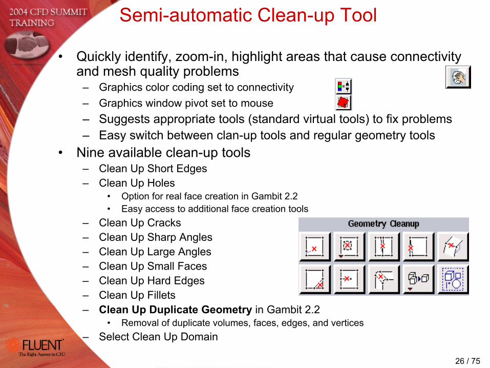
• Quickly identify, zoom-in, highlight areas that cause connectivity and mesh quality problems
– Graphics color coding set to connectivity– Graphics window pivot set to mouse– Suggests appropriate tools (standard virtual tools) to fix problems– Easy switch between clan-up tools and regular geometry tools
• Nine available clean-up tools– Clean Up Short Edges– Clean Up Holes
• Option for real face creation in Gambit 2.2• Easy access to additional face creation tools
– Clean Up Cracks– Clean Up Sharp Angles– Clean Up Large Angles– Clean Up Small Faces– Clean Up Hard Edges– Clean Up Fillets– Clean Up Duplicate Geometry in Gambit 2.2
• Removal of duplicate volumes, faces, edges, and vertices– Select Clean Up Domain
27 / 75
Semi-automatic Clean-up Tool
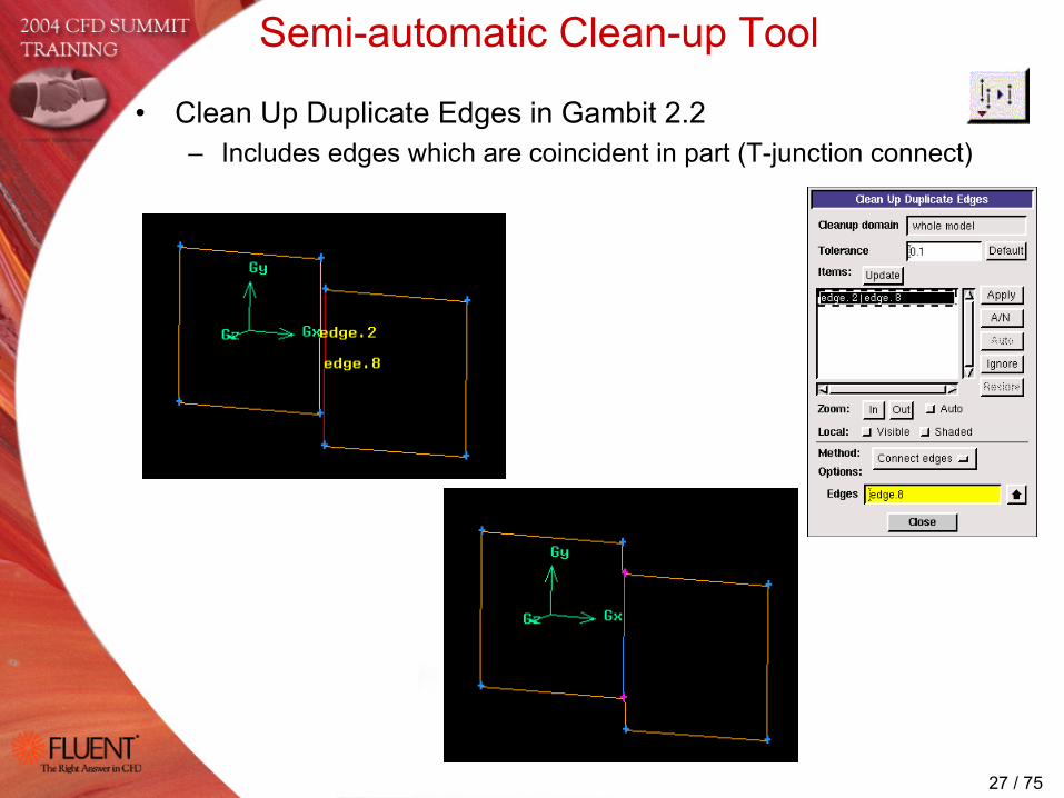
• Clean Up Duplicate Edges in Gambit 2.2– Includes edges which are coincident in part (T-junction connect)

28 / 75
Semi-automatic Clean-up Tool
• Clean Up Duplicate Faces in Gambit 2.2– Connects or deletes faces– Two search options
• Topology based– All lower topology has to be identical
• Centroid based – Less accurate, but helpful in detecting duplicate
faces with different lower topology

29 / 75
Semi-automatic Clean-up Tool
• Clean Up Duplicate Volumes in Gambit 2.2– Connects or deletes duplicate volumes
• Duplicate entities due to modeling errors or problematic import

30 / 75
Semi-automatic Clean-up Tool
• Clean Up Short Edges in Gambit 2.2– Edge merge and face merge in addition to vertex
connect• Automatic selection of edges and faces in merge
list, controlled by defaultsTOOLS.CLEANUP.FACE_MERGE_MIN_ANGLE = 135TOOLS.CLEANUP.EDGE_MERGE_MIN_ANGLE = 135
• Angles sharper than the defaults are cleaned up using vertex connect

31 / 75
Manual Virtual Clean-up Operations
• Eliminate short edges – Edge merge with adjacent edges
• Virtual (Tolerance) option allows to automatically merge short edges below a specified edge length
• Virtual (Tolerance) option with no value specified for ‘Max. Edge Length’ and ‘Min. Angle’ will merge all possible edges and automatically eliminate all vertices connected to exactly two edges
– Connect vertices (collapsing short edge between)• GEOMETRY.VERTEX.CONNECT_REMOVE_SHORT_EDGE
must be set to 1 in the defaults to connect the vertices defining the shortest edge
– Identify short edges using the ‘Highlight shortest edge’ button in the edge and face connect forms

32 / 75
Manual Virtual Clean-up Operations
• Eliminate sliver faces, small faces, sharp face angles– Merge face with neighbor face
• Virtual (Tolerance) option allows to automatically merge faces which form angles larger than ‘Min. Angle’
• Avoid merging faces which form sharp angles (≤ 90°). Sharp angle merge can cause meshing problems
– Set GEOMETRY.FACE.SHARP_ANGLE_MERGE in defaults to 1 in order to merge faces which form sharp angles
• Use ‘merge edges’ option in face merge GUI to automatically remove short edges
– Connect edges (collapsing sliver face between)• GEOMETRY.EDGE.CONNECT_REMOVE_DEGENERATE_FACE = 1
required to connect the edges defining the sliver face
• Eliminate sliver volumes– Connect faces (collapsing sliver volumes between)
• GEOMETRY.FACE.CONNECT_REMOVE_DEGENERATE_VOLUME = 1required to connect the faces defining the sliver volume

33 / 75
Example: Eliminate Short Edge
• Eliminate short edge by– Splitting off small face– Merging small face with adjacent face– Merging lower topology (merging edges)
– Alternative method: Connect vertices usingGEOMETRY.VERTEX.CONNECT_REMOVE_SHORT_EDGE = 1

34 / 75
Face connect with T-junction splits
• New functionality in Gambit 2.2, to ensure connectivity between non-aligned faces– Utilizes projections, splits, and connects– For real and virtual geometry, resulting geometry is always virtual– Easy connecting of poorly matching faces

35 / 75
• Tolerance used for virtual connect should be smaller than mesh size– If tolerance is larger than intended mesh size, or if mesh size is
smaller than merged/collapsed faces, meshing may fail– Mesh within the tolerance region gets pushed back to edge
Virtual Geometry Operations
For faces that overlap by a large amount, split each face with the intruding edge and form new face in center
For faces separated by a large gap, create new face to fill the gap

36 / 75
Connect Preserving Mesh
• Preserve higher topology mesh during edge and face connect– Mesh on unconnected entities must be topologically equivalent, but
can have different grading– Might require mesh smoothing after connect operation
• Allows easier meshing of geometry of repeated patterns– Copy geometry using ‘mesh unlinked’ option before connecting
‘Preserve first edge shape’ applies to mesh as well

37 / 75
• Face splits by– Face (Virtual)
• Set GEOMETRY.FACE.VIRTUAL_FACE_FACE_SPLIT to 1 in defaults• Bi-directional option• Try exporting surface meshes and splitting imported faceted faces if virtual face
split fails– Edges (Virtual)
• Endpoints of splitting edge need to be connected to edges of face• Tolerance for edge proximity to face
– Vertices (Virtual)• Tolerance option for vertex proximity to face• Can produce dangling edges• ‘Shaped edge’ option
– Locations (Virtual)• Locations snap to edges near boundaries• Manually drag and position temporary ‘Locations’• ‘Shaped edge’ option
Decomposing Virtual Geometry

38 / 75
Decomposing Virtual Geometry
• Volume splits by– Faces (Virtual)
• All split tool faces must be connected together • Must share boundary edges with volume boundary • If volume split fails (rarely), make volume invisible (keep lower topology
visible) and stitch together desired volumes– Locations (Virtual)
• Easy tool to split virtual volumes• Manually drag and position temporary ‘Locations’• Splitting volumes with voids not supported
39 / 75
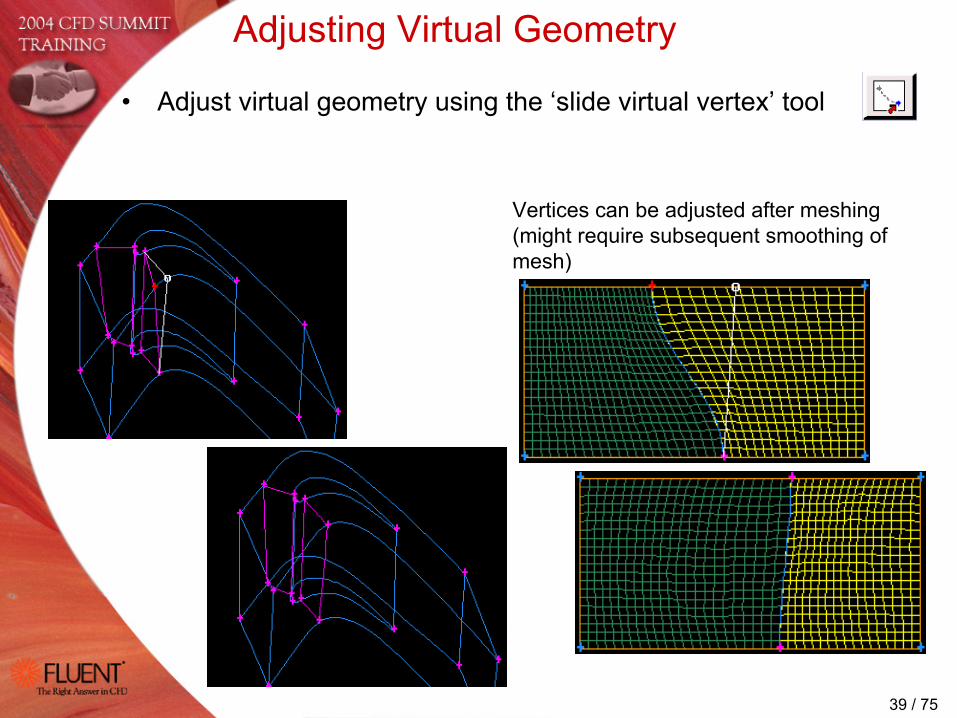
Adjusting Virtual Geometry
• Adjust virtual geometry using the ‘slide virtual vertex’ tool
Vertices can be adjusted after meshing (might require subsequent smoothing of mesh)
40 / 75
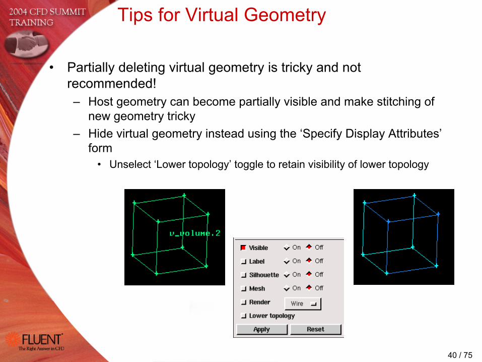
Tips for Virtual Geometry
• Partially deleting virtual geometry is tricky and not recommended!– Host geometry can become partially visible and make stitching of
new geometry tricky– Hide virtual geometry instead using the ‘Specify Display Attributes’
form• Unselect ‘Lower topology’ toggle to retain visibility of lower topology
41 / 75
Meshing Tools
• Size Functions• Boundary Layers• Miscellaneous meshing tools• Meshing tips

42 / 75
Size Functions
• Control mesh distribution on faces and in volumes– Eliminate the need to premesh edges manually– Automatically capture important geometry and flow features– Ensure high-quality meshes
• Primarily designed for unstructured meshing• Speed and robustness improvements in Gambit 2.2
Without Size Function Controlled growth rate with Size Function

43 / 75
Size Function Types
• Fixed– Controls mesh element size in a region as a function of distance
from a given location• Curvature
– Controls mesh element size as a function of geometric curvature of a face or edge and growth of mesh away from source
– Good for highly curved surfaces or edges• Proximity
– Controls the number of of mesh elements in a gap (edge gaps and face gaps) and growth of mesh away from gap
• Meshed– Uses existing mesh as initial size on source entity– New Size Function type in Gambit 2.2
44 / 75
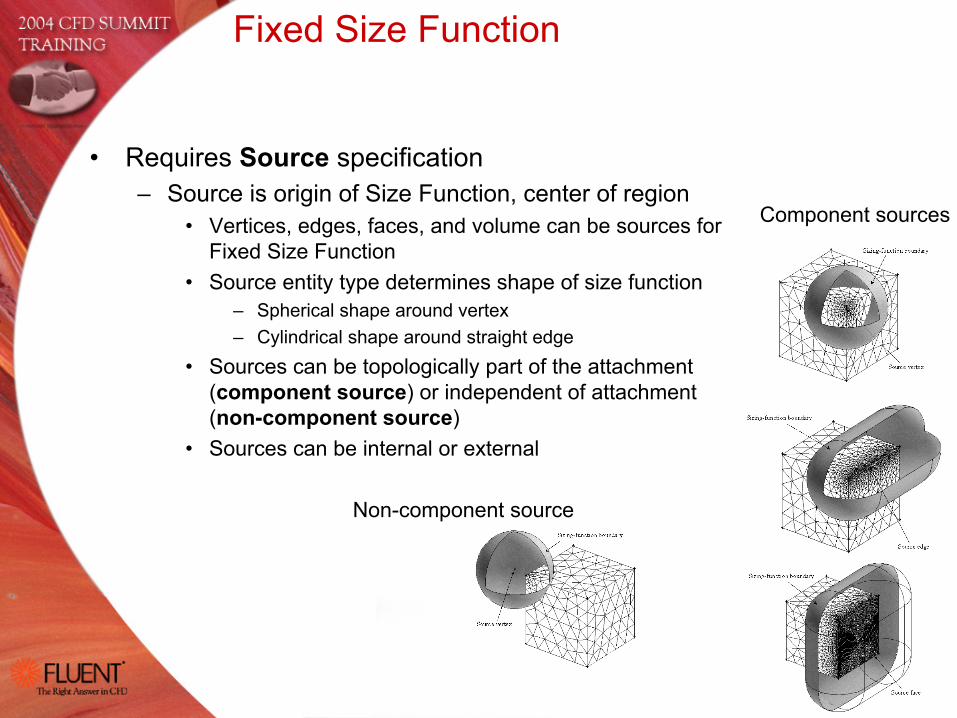
Fixed Size Function
• Requires Source specification– Source is origin of Size Function, center of region
• Vertices, edges, faces, and volume can be sources for Fixed Size Function
• Source entity type determines shape of size function– Spherical shape around vertex– Cylindrical shape around straight edge
• Sources can be topologically part of the attachment (component source) or independent of attachment (non-component source)
• Sources can be internal or external
Component sources
Non-component source

45 / 75
Fixed Size Function
Attachment volume
Attachment face
• Requires Attachment specification– Attachment is the mesh to be affected
• Fixed Size Function can be attached to edges, faces, and volumes
• Attachment is ideally the whole model to ensure high quality mesh
• Parameter specification– Start size
• Mesh element size at source– Growth rate
• Geometric stretching of mesh away from source• Cannot be less than 1.0
– Size limit• Maximum allowable mesh size for attachment• No further growth if size limit is reached
46 / 75
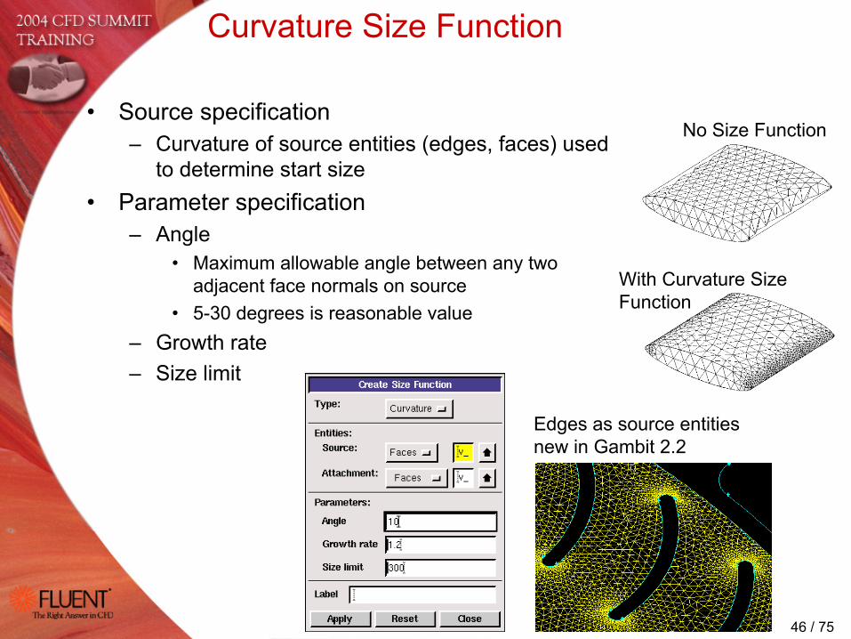
Curvature Size Function
• Source specification– Curvature of source entities (edges, faces) used
to determine start size • Parameter specification
– Angle• Maximum allowable angle between any two
adjacent face normals on source• 5-30 degrees is reasonable value
– Growth rate– Size limit
No Size Function
With Curvature Size Function
Edges as source entities new in Gambit 2.2

47 / 75
Proximity Size Function
• Source specification– Source entities which contain gap
• Gap is volumetric region between specified faces, or area between opposing edges of specified face
• Parameter specification– Cells/gap
• Minimum number of mesh cells in gap– Growth rate– Size limit
Gap defined by one source face
Gap defined by two source faces

48 / 75
Meshed Size Function in Gambit 2.2
• Ensures that mesh grows controlled away from a premeshed source entities (edges or faces)– Very useful after importing mesh– Local start size taken from premeshed source entities
• Parameter specification– Only growth rate and size limit are required

49 / 75
Background Grid
• Use of the background grid default parameters is keyto obtaining the desired meshes
– TOOLS.SFUNCTION.BGRID_MAX_TREE_DEPTH controls the maximum refinement of the background grid
• Increase the default value (16 in Gambit 2.2) until no cells hit the tree depth as reported in the transcript window
• A value of –1 puts no limits on the background tree depth, but makes Size Functions slow for larger models
– TOOLS.SFUNCTION.NONLINEAR_ERR_PERCENTcontrols the allowable deviation of the local mesh from the prescribed mesh size
• Default is 25%, can vary between 3 and 25%• Number of cells above the prescribed tolerance are
reported in the transcript window– TOOLS.SFUNCTION.REPORT_BGRID_INFO = 1 turns
reporting in the transcript window on (on by default)

50 / 75
Background Grid• Use the Size Function reporting in the Transcript window
– If the mesh is noticeably changing as BGRID_MAX_TREE_DEPTH is increased, it is a sign that too many background grid cells are hitting the limit
Ideal background grid
Background grid level reached maximum value specified
Size Function not sufficiently resolved
Underresolved BGRID Resolved BGRID
51 / 75
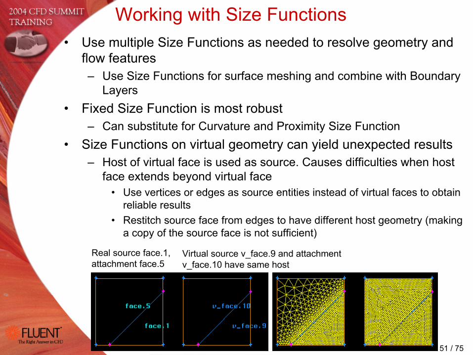
Working with Size Functions• Use multiple Size Functions as needed to resolve geometry and
flow features– Use Size Functions for surface meshing and combine with Boundary
Layers• Fixed Size Function is most robust
– Can substitute for Curvature and Proximity Size Function• Size Functions on virtual geometry can yield unexpected results
– Host of virtual face is used as source. Causes difficulties when host face extends beyond virtual face
• Use vertices or edges as source entities instead of virtual faces to obtain reliable results
• Restitch source face from edges to have different host geometry (making a copy of the source face is not sufficient)
Real source face.1, attachment face.5
Virtual source v_face.9 and attachment v_face.10 have same host

52 / 75
Working with Size Function
• Size function preview uses simple background grid– Increase TOOLS.SFUNCTION.VISUAL_GRID_MAX_LINE_NUM (default
value = 25) if the size limits in the size function preview do not match the specified limits
SF start size = 0.01 Preview start size 0.02222

53 / 75
Boundary Layers
• Produce high quality cells near boundary– Attachment to edges for 2D BL– Attachment to faces for 3D BL
• Uniform or aspect ratio based BL– Uniform
• First row height as parameter• Difficulties on highly curved geometry
– Aspect ratio based• Aspect ratio of first cell is parameter• Does well in concave corners• Cannot directly control first cell height

54 / 75
E
E
ES
CE
E
E
R
E
2D Boundary Layers
• Boundary layer shape near vertices depends on vertex type– End (E) type
BL mesh butts up against adjoining edgeOverlapped mesh where two BL meet
– Side (S) typeAngle at vertex is bisectedContinuous BL‘Internal continuity’ enforced by manually changing vertex type to S
– ‘Wedge corner shape’ option for corner (C) and reversal (R) verticesWedge corner shape applies to 2D BL onlyCan be combined with Cooper tool for quasi-3D BL
Wedge corner shape off Wedge corner shape on

55 / 75
3D Boundary Layers
• Internal continuity– Allows boundary layers to be formed without
crossover region
• Imprinting on adjacent face– Default MESH.BLAYER.PROJECT_ADJACENT_ANGLE
removed in Gambit 2.2– Single default MESH.VERTEX.MAX_END_ANGLE (=120o
by default) for consistent imprinting of 2D and 3D BL
Internal continuity ‘on’
Internal continuity ‘off’
Gambit 2.1

56 / 75
3D Boundary Layers
• Different 3D BL settings allowed onadjacent surfaces in Gambit 2.2
• Imprinting of 3D BL fails if adjacent volume has already BL attached
– Modify existing BL instead
• Dangling 3D BL are not supported
57 / 75
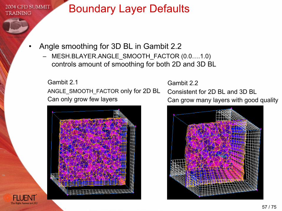
Boundary Layer Defaults
• Angle smoothing for 3D BL in Gambit 2.2– MESH.BLAYER.ANGLE_SMOOTH_FACTOR (0.0….1.0)
controls amount of smoothing for both 2D and 3D BL
Gambit 2.1ANGLE_SMOOTH_FACTOR only for 2D BLCan only grow few layers
Gambit 2.2Consistent for 2D BL and 3D BLCan grow many layers with good quality

58 / 75
Boundary Layer Defaults
• Height transitioning for 3D BL– MESH.BLAYER.HEIGHT_TRANSIT_RATIO controls how fast the BL height
changes when sides of BL attach to premeshed edges> 1 = number of cells over which height changes from premeshed edge
to specified height< 1 = fraction of edge length
Gambit 2.1Only for 2D BL
Gambit 2.2HEIGHT_TRANSIT_RATIO consistent for 2D and 3D BL

59 / 75
• Use normal and offset smoothing when BL generates skewed elements in concave corners– Normal Smooting
• Direction of advancing normals is smoothed to avoid collapsing of BL
NORMAL_SMOOTH_ITER (default = 10)NORMAL_SMOOTH_ANGLE (default = 10o)NORMAL_SMOOTH_CONVERGED (default = 0.0o)NORMAL_SMOOTH_LOCALLY (default = 1)
– Offset Smoothing• Eliminates dips in the advancing layers
OFFSET_SMOOTH_ITER (default = 0)OFFSET_SMOOTH_CONVERGED (default = 0.01)
Boundary Layer Defaults

60 / 75
Boundary Layer Tips
• Use MESH.BLAYER.QUICK_N_DIRTY to control the graphics display during BL creation and attachment
= 0 Project BL using MESH.BLAYER.USE_FACET_EVALS and take attached Size Functions into account
1 Do not project BL, but use Size Functions (default)2 Do not project, disregard Size Function (fastest)
• Deactivate the display of the temporary BL as it is being defined
• Arrow of temporary BL points toward the label (ID) of the face/volume into which the BL grows– Can be misleading when attaching BLs

61 / 75
Meshing of Periodic BC
• Hard-link face meshes before meshing– Use periodic option to ensures periodicity of mesh
(ensures periodicity even when one of the edges is split)– Reverse orientation active as default– Can hard-link multiple pairs of periodic faces in same
volume• Assign PERIODIC boundary type
– Multiple hard-linked face pairs can be picked as one periodic zone
• Export mesh• Fluent 6 correctly recognizes node pairing of
periodic boundary conditions– Default periodic type is ‘translational’ in Fluent 6
62 / 75
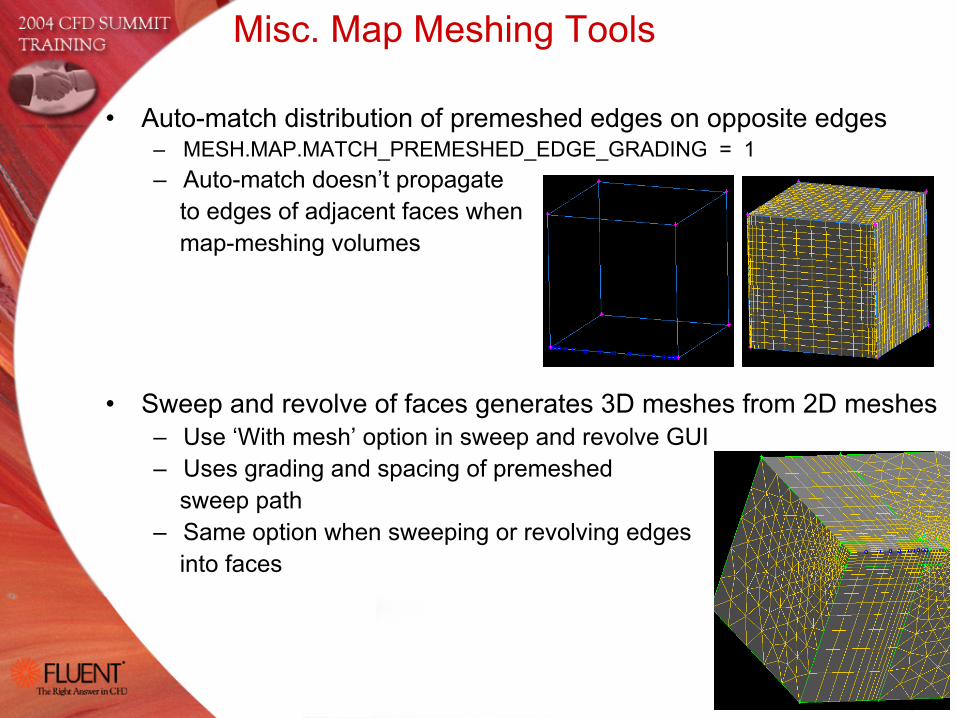
Misc. Map Meshing Tools
• Auto-match distribution of premeshed edges on opposite edges– MESH.MAP.MATCH_PREMESHED_EDGE_GRADING = 1– Auto-match doesn’t propagate
to edges of adjacent faces whenmap-meshing volumes
• Sweep and revolve of faces generates 3D meshes from 2D meshes– Use ‘With mesh’ option in sweep and revolve GUI– Uses grading and spacing of premeshed
sweep path– Same option when sweeping or revolving edges
into faces

63 / 75
• Poor mesh by mapper on highly curved surfaces– Projection to the surface distorts the mesh– Smooth the face mesh using ‘Winslow’ scheme
(only available for quad elements)
Meshing Tips
• Surface meshing done on faceted face representation by default– MESH.FACE.EXACT_MESH_EVALS = 0
• Final exact projection from facets to surface by default– MESH.FACE.PROJECT_TO_SURFACE = 1– Turn final projection off and leave mesh on facets if projection
generates skewed or degenerated mesh on bad/corrupt surfaces
PROJECT_TO_SURFACE = 0PROJECT_TO_SURFACE = 1

64 / 75
Meshing Tips
• If Tet/TGrid fails to initialize the volume mesh– Inspect quality of surface mesh– Turn on verbosity in defaults MESH.TETMESH.VERBOSITY = 1
• Reports number of uninitialized nodes• Likely fixable if only few nodes fail to initialize
– Export surface mesh and try meshing volume in TGrid• TGrid allows to visualize uninitialized nodes
• Example 1: Nose cone of missile– Initialization fails due to collapsed surface elements– Fix: Split nose cone and create separate face for first element
65 / 75
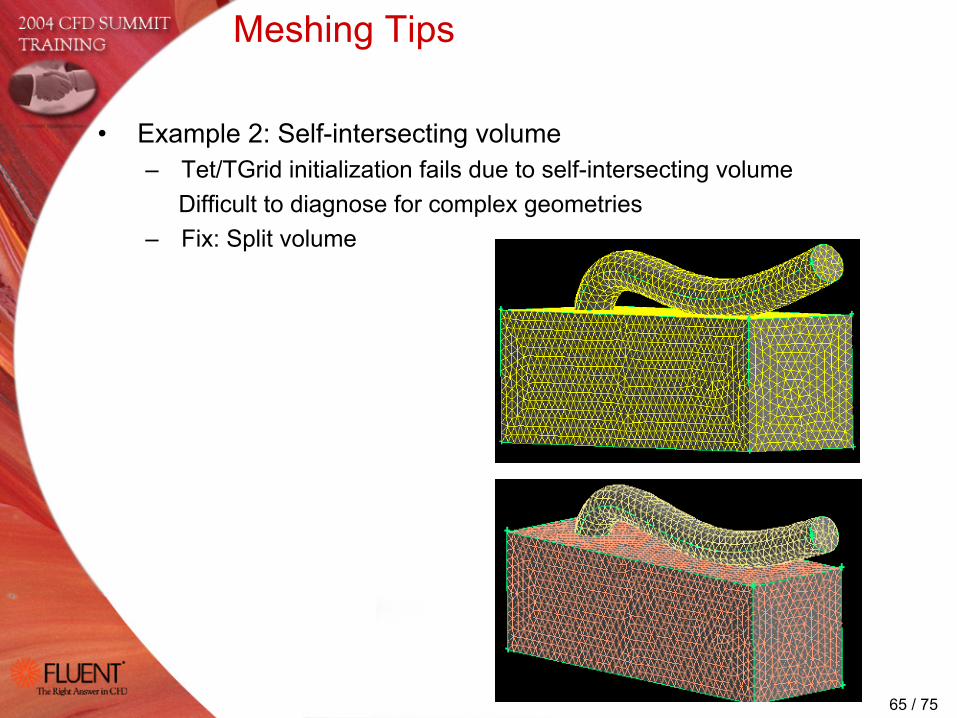
Meshing Tips
• Example 2: Self-intersecting volume– Tet/TGrid initialization fails due to self-intersecting volume
Difficult to diagnose for complex geometries– Fix: Split volume

66 / 75
Meshing Tips
• Default limit for tri elements on single face is 100’000– Increase limit in defaults MESH.TRIMESH.MAX_FACES or use a
value of –1 for no restriction
• Mesh size limits– Memory estimate for single volume with 1 million cells
Hex mesh: 190MBTet mesh: 340MB (about 6 million tet cells max. on 2GB machine)
– Access additional swap space on UNIX/Linux platforms (requires 3GB of swap space on disk)
setenv FLUENT_MMAP_PATH “/tmp/filename”setenv FLUENT_USE_MMAP 1Gives access to more memory and allows larger models

67 / 75
Meshing Tips
• Mesh delete – Delete volume or face mesh using ‘Remove unused
lower mesh’ removes edge mesh, but does not reset assigned edge grading and spacing
– Delete edge mesh without using ‘Reset to default values’ deletes the edge mesh, but retain the assigned grading and spacing
• ‘Reset to default values’ restores the default spacing specified inMESH.INTERVAL.COUNTMESH.INTERVAL.SIZE

68 / 75
Mesh Export
• Native Fluent 6 export– Exports mixed (volume + surface) mesh– Exports surface mesh without specifying the boundary conditions
• Unspecified boundaries will be ‘wall’– ‘Export 2d Mesh’ option
• Ensures proper 2D mesh format for Fluent 6• Default FILE_IO.MESH.EXPORT_2D_TOLERANCE = 0.0001 is used to
determine whether mesh is in xy-plane
• ‘Utility’ export option available through defaults– FILE_IO.FLUENT5.EXPORT_USING_UTILITY = 1– For rare cases where direct Fluent 6 exports fails– Exports only volume mesh– Exports surface mesh only for surfaces with specified boundary
conditions if FILE_IO.FLUENT5.EXPORT_SURFACE_MESH_ONLY = 1
69 / 75
Miscellaneous Tips and Tricks
• Geometry display and faceting• Boundary zone coloring• Picking entities• Journal files
70 / 75
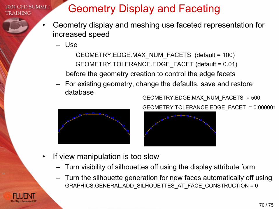
Geometry Display and Faceting• Geometry display and meshing use faceted representation for
increased speed– Use
GEOMETRY.EDGE.MAX_NUM_FACETS (default = 100)GEOMETRY.TOLERANCE.EDGE_FACET (default = 0.01)
before the geometry creation to control the edge facets – For existing geometry, change the defaults, save and restore
database
• If view manipulation is too slow– Turn visibility of silhouettes off using the display attribute form– Turn the silhouette generation for new faces automatically off using
GRAPHICS.GENERAL.ADD_SILHOUETTES_AT_FACE_CONSTRUCTION = 0
GEOMETRY.EDGE.MAX_NUM_FACETS = 500
GEOMETRY.TOLERANCE.EDGE_FACET = 0.000001

71 / 75
Color by Zone Type/ID
• Option to color zones by zone type or by zone ID– Similar to Fluent and TGrid– GRAPHICS.GENERAL.ZONECOLOR_TYPE = [0, 1]
• Change the default black background color– GRAPHICS.GENERAL.WINDOWS_BACKGROUND_COLOR
0 – color by ID 1 – color by type
72 / 75
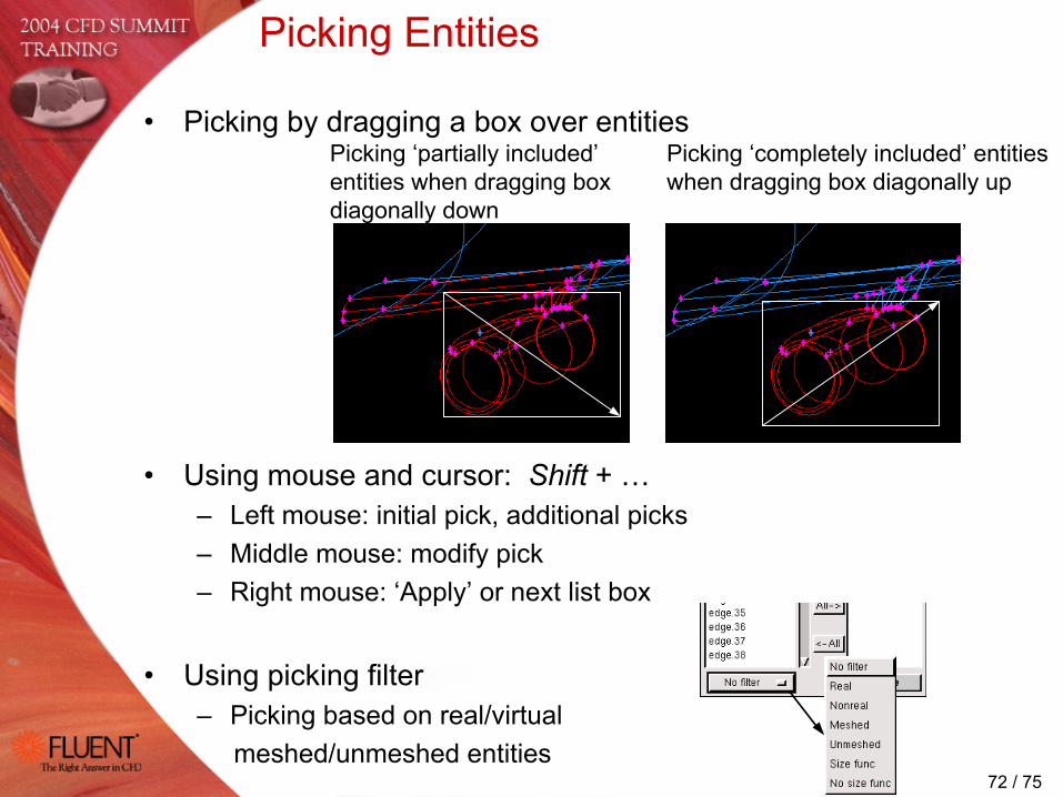
• Picking by dragging a box over entities
• Using mouse and cursor: Shift + …– Left mouse: initial pick, additional picks– Middle mouse: modify pick– Right mouse: ‘Apply’ or next list box
• Using picking filter– Picking based on real/virtual
meshed/unmeshed entities
Picking Entities
Picking ‘completely included’ entities when dragging box diagonally up
Picking ‘partially included’ entities when dragging box diagonally down
73 / 75
Journal Files
• Extracting lost journal file from existing database filegambit –res(torejournal) journalfile –id database
• Tips to minimize impact when running old journal files– Use default GUI.GENERAL.JOURNAL_ENTITY = 1 or 2 to generate ID
independent labels, if possible0 – journal original labels (default)1 – journal lastid, i.e. creation order2 – journal entity location
– Set GEOMETRY.VOLUME.BOOLEAN_METHOD = 0 to use old Boolean/imprinting method
– Set GEOMETRY.GENERAL.REAL_LABEL_CHANGE_MINIMIZATION = 0 when running Gambit 2.0 journal files
– Set GEOMETRY.FACE.VIRTUAL_FACE_SPLIT_METHOD = 0 to get old behavior

74 / 75
Miscellaneous Tips and Tricks
• Use Edit Defaults to customize default settings– For example, set GLOBAL.GENERAL.SOLVER = 64 for Fluent 6 use– Save defaults in ~/Gambit.ini file– More information on the defaults is in the Gambit Defaults Guide at
www.fluentusers.com
• Most Gambit documentation is in the Modeling Guide!– Use Quick Help to directly access the complete documentation

75 / 75
Summary
• GAMBIT continues to improve pre-processing efficiency – Improved robustness and speed– Improved real geometry tools– Extended automatic clean-up– Improved meshing tools
• Go try this at home….– Create real non-planar faces– Stitch volumes with voids– Quickly find duplicate entities– Connect faces with T-junctions– Split entities with Locations– Mesh with fast Size Functions Thank You…!