Galaxy BA Teil 1 E - ARRI Rental · Please observe DIN 15019 to have enough time to dismantle the...
29
1 Operating Manual Panther Galaxy Crane
Transcript of Galaxy BA Teil 1 E - ARRI Rental · Please observe DIN 15019 to have enough time to dismantle the...

1
Operating Manual
Panther Galaxy Crane

2
Introduction Congratulations to your decision to buy or rent a PANTHER GALAXY CRANE!We are very pleased that you have chosen our product, which combines state-of-the-art technology as well as the experience of many years in manufacturing camera cranes and dollies. High-quality material and sound know-how, as well as a clever concept enable your PANTHER GALAXY CRANE to do a professional job, which you will really enjoy when doing your responsible work at the set. Your new PANTHER GALAXY Crane is a high-quality tool, which enables the creative camera man to do an excellent job – fast and easy – with fantastic shots and camera drives. The PANTHER GALAXY Crane is a product that has been created and built by experts for experts – to satisfy the high demands of every grip and camera man. We hope that you will have a lot of pleasure with your PANTHER GALAXY CRANE. In order to guarantee the highest security and reliability in our product at the set, please study our operating manual very carefully! All the best Panther GmbH

3
Index
Subject Page Introduction 2 Index 3 To the grip 4 Safety instructions 4 General instructions 5 Check list for assembling 6 Operating- and safety advice 7-8 The Panther Galaxy Crane 9 Assembly instruction 10-19 Special accessories 20 First operation 21-24 Transport 25 Service and maintenance 26 Technical Data 27-29

4
To the grip Sloppy assembly, disassembly and operating have created and will also create in future damages and physical injury, as well as death of involved or even uninvolved persons. The following operating instructions should explain to the grip how to work with the camera crane and should also make aware and give advice to take care of possible dangers. Accidents can only be avoided if the dangers are well known and the common sense is activated.
Safety instructions Please start working with the crane only after studying the complete instruction manual and understanding everything. Safety advice, measurement and weight indications, as well as the repair and maintenance instructions have to be observed carefully. Lifting, swivel and operating range of the crane including the complete outrigger must be kept free. The safety distance of ≥ 0,5 m to all parts of the surrounding have to be kept free from all sides. Attention: It is not allowed to use the crane on inclined planes. The CRANE has to be secured so that is cannot slip away. The underground has to be hard and inflexible. The minimum carrying capacity of the underground has to be 4000 kg / m². The crane should never be left unattended in assembled state. It has to be secured that persons without authorization cannot use the crane. If necessary adequate measures against heavy wind or storm have to be taken. Before starting operation the crane‘s stability with the maximum tilting moment has to be checked. When working in the studio or with tracks it has to be observed that no hard or loose parts can get under the wheels. Also slight unevenness can endanger standing– and driving security. Do only use Panther original accessories. Combined seat extensions (vertical/horizontal) with the order numbers 110, 111, 112, 105663, 105662, 105661 must not be used. Use only vertical seat extensions or combined seat extensions marked with “HD” (=heavy duty).

5
General instructions Only trained persons are allowed to work with the PANTHER GALAXY CRANE. Panther GmbH offers training work shops which will enable the participants to work with the Panther Galaxy Crane. The participants will receive a certificate at the end of this seminar. For more information regarding the actual dates or to book, please contact 089/61390001.
Repairs should only be carried out by the manufacturer or persons, who received a special training. Panther GmbH offers service seminars, which can be held according to your desires. Should you be interested, please contact 089/61390030 (Panther-Service). The PANTHER GALAXY Crane may only be assembled according to this operating instruction. The instruction manual has to be studied and understood completely. To avoid the danger of a tire blowout, twin tires should be mounted at the mammoth base. Maximum wind speed: 45 km/h (6 Beaufort) for all remote versions 32 km/h (5 Beaufort) for 1 man platform operation 22 km/h (4 Beaufort) for 2 man platform operation The operation of the Galaxy Crane is not allowed if the wind speed exceeds the above values. Please observe DIN 15019 to have enough time to dismantle the crane if a storm comes up. The PANTHER GALAXY Crane can only be assembled according to the assembling versions shown in this operating instruction.

6
Check-List for Assembling Please check which crane version is best for your shooting. The following points have to be considered: - height - limits in weight - working distance - ultimate load needed - space limits - platform - operation - access to shooting place - remote - operation Take your time to securely assemble the crane, to check and to test the crane before use. Transport
Do not expose the outriggers, balance rods and anchor poles to heavy strokes. Auxiliaries
Water level Support device Small ladder / Rostrum
Ground
No slope: check with water level Use sub-base if slope If the ground can only be loaded up to 4000 kg/ m² the load has to be distributed
by a reasonable sub-base. Basis
No slope: check with water level Min. 3000 kg / m² load capacity of sub-base
Assembly
Check whether all necessary parts are available Assemble according to instruction IMPORTANT: The crane arm must be balanced in each condition. The
assembly support cannot bear the full load of the counterweight. Safety instructions
Observe safety instructions

7
Operating and safety advice The crane operator is obliged to inform the persons on the platform that they have to use a safety belt. The persons are only allowed to leave the platform after enough counterweights have been removed from the counterweight bucket. Please do not leave loose parts on the platform or the remote head mount. They can fall and injure persons. The crane may never be left unattended in assembled state. The crane has to be disassembled or protected against wind when out of service. Please observe DIN 15019 to have enough time to dismantle the crane if storm comes up. The vertical and horizontal swiveling area must be kept free. The safety zone of ≥ 0,5 m must be kept free in all directions. Please look out for possible pinching dangers during assembly and operation. When turning and rotating the crane outrigger and during curve drives, centrifugal forces can appear which can endanger the standing stability when added. For safety reasons it is obligatory that the crane stands/drives on absolutely hard, stable and inflexible ground, which is completely leveled. Please pay attention that no hard or loose objects can get under the wheels, so that the standing and driving stability of the crane could be endangered. Example: Cable in the studio. This also applies when working with tracks. Do not exceed the maximum payload of the platform or the remote head mount. Please only use the maximum number of weights allowed which fit into the counterweight bucket. The use of additional weights, such as sand bags, is not allowed. For the payload of the base, tracks or supports for the complete crane weight including all accessories and persons have to be considered. Support material such as wedges and blocks have to be fixed in a way that they cannot slip away, fall out or be pushed away. At the end of the tracks clips or similar safety stops have to be fixed to avoid that the crane could fall down. Please check the crane every day with regard to function, damages and missing parts. Damaged or missing components have to be replaced by new ones immediately. Mark the operating range (pan and tilt area) of the crane with flags, stickers or similar material. Keep all persons out of the operating area in order to avoid anybody to be hurt by the base dolly or the outrigger. Getting on and off the crane is only allowed if the operator has given his approval. Getting off a balanced crane causes an abrupt rising of the outrigger and can cause damage to the crane itself or severe injuries to persons.

8
Do not use the crane in the vicinity of high-tension lines. In case the crane is used on elevated areas (e.g. bridges, sky scrapers) it is recommended to additionally secure the persons on the platform by a security rope at a second object (e.g. concrete post) in order to lower the risk of falling. Do not work with persons on the platform under extreme weather condition – be it naturally or imitated – e.g. heavy rain, thunder and lightning, extreme heat or cold unless those persons are secured sufficiently. The crane may not be operated if there is the danger of being struck by lightning. After shooting the crane has to be dismantled or secured against wind. Please observe DIN 15019 part 1/6.1.3. to have enough time to dismantle the crane if a storm comes up. After shooting, especially after use under dirty, dusty, sandy, humid and salty conditions the crane has to be thoroughly cleaned and serviced. Keep the security belts in good condition. Take care that the outrigger does not touch anything within the rotating area. Check the surrounding of the crane for possible dangers. Stop working with the crane immediately, even if only a small part is damaged or not mounted the correct way. Use exclusively original PANTHER accessories and spare parts.

9
The Panther Galaxy Crane
Galaxy Parts/ EinzelteileCode/Nr. Description/Beschreibung
10
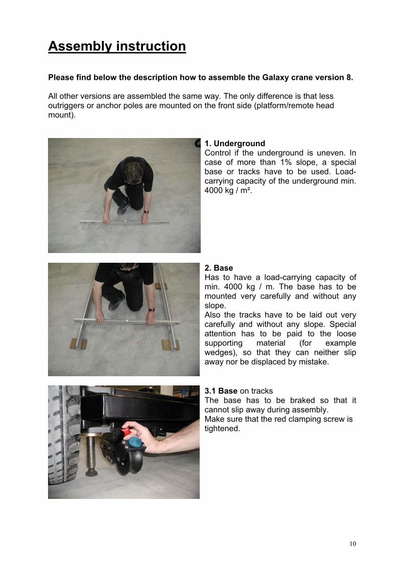
Assembly instruction Please find below the description how to assemble the Galaxy crane version 8. All other versions are assembled the same way. The only difference is that less outriggers or anchor poles are mounted on the front side (platform/remote head mount).
1. Underground Control if the underground is uneven. In case of more than 1% slope, a special base or tracks have to be used. Load-carrying capacity of the underground min. 4000 kg / m².
2. Base Has to have a load-carrying capacity of min. 4000 kg / m. The base has to be mounted very carefully and without any slope. Also the tracks have to be laid out very carefully and without any slope. Special attention has to be paid to the loose supporting material (for example wedges), so that they can neither slip away nor be displaced by mistake.
3.1 Base on tracks The base has to be braked so that it cannot slip away during assembly. Make sure that the red clamping screw is tightened.

11
3.2 Base on the floor The base has to be braked so that it cannot slip away during assembly. If the ground is not 100 % even, the base has to be leveled with the spindles.
4. Pyramid The pyramid has to be put onto the base and screws must be tightened.
5. Central Pivot Section The central pivot section has to be put onto the pyramid and screws must be tightened.
6. Outrigger 3 Mount outrigger 3 to the central pivot section and fasten the locking bolt. It does not matter at which side of the central pivot section outrigger 3 will be mounted.

12
7. Assembly support An assembly support (e.g.Ladder) can be used as support device when mounting the outrigger. Further a rostrum can help.
8. Balance rod The balance rod of outrigger 3 is fastened at the pivot section and at the swiveling unit by means of a locking bolt.
9. Outrigger 1 Outrigger 1 is mounted at the pivot section and secured with the locking bolt.
10. Outrigger 1 Mount the second outrigger 1 at the first outrigger 1 and secure it with the locking bolt. The corresponding balance rods are inserted into the support and secured with the locking bolts.

13
11. Counterweight bucket Note: For mounting the counterweight bucket, the assembly support needs to be removed. Move the opposite outrigger downward and mount the counterweight bucket.
12. Counterweight bucket Move the opposite outrigger about 1 m upwards and secure the counterweight bucket with the locking bolt.
13. Outrigger 4 After returning an assembly support (ladder), outrigger 4 is mounted to outrigger 1 and secured with the locking bolt. Then the balance rod is mounted as described above. Attention: The assembly support must always be positioned underneath the center of gravity (bucket).
14. Balance For keeping the crane arm balanced 10 counterweights are put into the bucket. Attention: Watch the max. load of the assembly support (ladder).

14
15. Trapezoid One side of the trapezoid is screwed tight to the pivot section. Note: A ladder or a push rod facilitate the assembly. Now the cross member is inserted at the connection and secured with a locking bolt. .
16 Trapezoid The second side of the trapezoid is screwed tight to the pivot section and connected with the cross member.
17. Anchor pole The “anchor pole variable, back” is mounted at the back of the trapezoid (right side of picture) and outrigger 3 and secured by means of splint pins. The base anchor pole is mounted at the front of the trapezoid and secured with splint pins.
18. Anchor pole An extension is inserted into the base anchor pole and secured with the locking bolt.

15
19. Anchor pole The “anchor pole variable, front” is first mounted and secured to the extension, then to outrigger 4.
20. Anchor pole All turnbuckles of the anchor poles are tensioned manually, so that they fit into the receiving bolt. Special tools are not required and may not be used – if tension is too high the outriggers may be bent upwards. .
21 Outrigger 1 Outrigger 1 is mounted to outrigger 4 (with the anchor pole already mounted) and secured with the locking bolt.
22. Support The anchor pole support is put onto the connection plate of outrigger 4 and secured with the corresponding locking bolt. Note: this locking bolt is a little bit longer and only used in connection with the support. The locking bolt of outrigger 1 is put aside – make sure it will not be lost.

16
23. Balance In order to keep the crane arm balanced 20 counterweights are placed into the bucket. Attention: Watch the max. load of the assembly support (ladder).
24 Outrigger 1 + 4 First another outrigger 1 is mounted, then another outrigger 4 is added on and secured with the locking bolt.
25. Balance To keep the crane arm balanced, another 10 counterweights are placed into the bucket. Attention: Watch the max. load of the assembly support (ladder). The assembly support must always be positioned underneath the center of gravity (bucket).
26 Anchor pole The anchor poles for the front holder are mounted and secured as described above. Note: Of course, this requires an adequate number of extensions other than described above.

17
27. Support The anchor poles are placed at the support and adjusted.
28. Balance To keep the crane arm balanced, another 10 counterweights are placed into the bucket. Attention: Watch the max. load of the assembly support (ladder). The assembly support must always be positioned underneath the center of gravity (bucket).
29. Outrigger 5 Outrigger 5 is mounted to outrigger 4 and secured with the locking bolt. The balance rod is inserted at the upper holder of the support and secured.
30. Outrigger 6 Outrigger 6 is mounted to outrigger 5 and the connection screw is screwed tight manually.

18
31. Outrigger 6 Use the locking lever to clamp the connection in place.
32. Foxy Remote Head Mount The Foxy remote head mount is mounted and secured. The balance rod (in this case with turnbuckle) is mounted and secured with the locking bolt. Attention: even if the remote head mount is fixed by its own weight, the two red screws need to be tightened. Otherwise the remote head mount may fall down during driving.
To disassemble, please proceed in reverse sequence.

19
Assembly instructions for other crane versions: Instead of outrigger 5+6, also outrigger 2
can be mounted to hold the remote head mount. For these versions the Galaxy remote head mount is used instead of the Foxy remote head mount. Besides the self-locking device also the two locking bolts have to be mounted.
Besides the self-locking device at outrigger 2 also the two locking bolts have to be mounted.
Attention: The maximum outrigger lengths and payloads may not be exceeded. Please pay attention to the diagrams in the end of this operating instruction.

20
Special accessories: Counterweight Bucket for 45 weights:
A compact counterweight bucket can be used for shorter crane versions. It gives better visibility to the front and it is more handy for transport and set up due to less weight and smaller dimensions. Compared dimensions: left: Counterweight Bucket for 80 weights measurements: l 42 x w 73 x h 118 cm right: Counterweight Bucket for 45 weights measurements: l 42 x w 56 x h 93 cm
The counterweight bucket for 45 weights is siutable for the Galaxy crane up to the version 5 remote or version 3.1 platform. Also longer crane versions can be equipped with reduced payload on the plattform/remote mount. Attention: Use only the maximum number of counterweights allowed to be put inside the counterweight bucket. It is not allowed to use additional weights, such as sand bags. Trapezoid, compact:
A compact trapezoid can be used for shorter crane versions. It gives better visibility to the front and it is more handy for operation and set up due to smaller dimensions. Compared dimensions: Left: Trapezoid (standard) measurements: l 71 x w 123 x h 94 cm right: Trapezoid (compact) measurements: l 71 x w 78 x h 58 cm
The Trapezoid compact is siutable for the Galaxy crane up to the version 5 remote or version 3.1 platform. Attention: Longer versions must not be set up with the Trapezoid compact!

21
First operation Important: before each loading (platform, remote head mount, counterweight bucket) and first operation it needs to be checked if all connection are tight.
Advice regarding the payload: The payload of the platform is the sum of the weight of the person(s), as well as the weight of all accessories (turnstile, bazooka, seat, etc.) and the camera with all accessories. The payload of the remote head mount is the sum of all parts that are mounted on the remote head mount (remote head, camera, objective, etc.). Maximum payloads: Platform crane Remote crane Version 1: 250 kg Version 1: 80 kg Version 2: 250 kg Version 2: 80 kg Version 3: 150 kg Version 3: 80 kg Version 3.1: 250 kg Version 3.1: 80 kg Version 4: 250 kg Version 4: 80 kg Version 5: 200 kg Version 5: 80 kg Version 6: 130 kg Version 6: 80 kg Version 7: 50 kg Version7.1: 80 kg Version 8: 50 kg Version 8.1: 65 kg The maximum payloads for platform or remote head mounts may absolutely not be exceeded. Maximum wind speed: 45 km/h (6 Beaufort) for all remote versions 32 km/h (5 Beaufort) for 1 man platform operation 22 km/h (4 Beaufort) for 2 man platform operation When loading the remote head mount or the platform- they have to be supported under the center of gravity.

22
Attention: If the crane is balanced and no longer supported, it is not allowed to leave the platform. The person(s) on the platform have to use a safety belt. The assembly support (ladder) only serves during assembly – it is not destined to support the full counterweight bucket.
Loading the counterweight bucket Please do not exceed the maximum pay- load of the platform or of the remote head mount. Use only the maximum number of counterweights allowed to be put inside the counterweight bucket.It is not allowed to use additional weights, such as sand bags. Please always close the door. The weights are only secured if the door of the counterweight bucket is closed. Attention: The assembly support must always be positioned underneath the center of gravity (bucket). The crane may tipp over if the support is not positioned correctely.
Fine adjustment With the fine adjustment counterweight the fine adjustment of the balance is effected. It is mounted on a balance rod and tightened with the screw.

23
Further applications and special accessories:
Push rod On two sides, push rods can be inserted into the pyramid. They are secured with the security splint.
Adapter for sun-/rain shield If required a sun or rain shield can be attached to the platform or the remote head mount.
Monitor mount The monitor mount is fastened at outrigger 3 with screws.
For mounting the twin wheels distance axes are used.
Like the pneumatic wheels the studio wheels are secured with the splint pin.
Use the red screw to fasten the track wheels.

24
Both, the large or the small platform can be attached to the platform mount Alternatively a remote adapter is available.
After reading the operation manual has to be put back into the pyramid.

25
Transport The Galaxy crane has been designed in a way that all crane elements can be transported comfortably and easily by two persons.
7 outriggers, all balance rods and bracing kits, as well as the assembly support can be transported with this transport cart.
The following components can be fit onto the transport cart: central pivot section counterweight basket Outrigger 1 Outrigger 2 Outrigger 3 as well as other accessories such as seats, bazooka etc.
The platform and the remote head mounts can be put onto the pyramid. If necessary (e.g. lack of space in a truck) the mammoth base can also be stored or transported upside down.
All components have to be secured against falling down by suitable means. The Galaxy can be placed on the truck with a lifting platform. In any case it is prohibited to transport or lift the Galaxy with a crane. Also the Galaxy may never be attached to any kind of motor tractor.

26
Service and Maintenance The Panther Galaxy Crane is a very solid piece of equipment. It works reliably and does not require a lot of maintenance work. To guarantee a long life and a consistently stable quality, it is advisable to treat all elements of the crane very carefully. We do not accept any warranty claims for damages occurred due to inappropriate handling. After working with the crane, particularly after working in a dirty, dusty, sandy, wet and salty surrounding, the crane has to be cleaned and maintained properly. Please keep the safety belts in good condition. Immediately interrupt working with the crane in case even the smallest part of the crane is damaged or missing. Maintenance and repair should only be carried out by trained and experienced persons. Panther GmbH offers service seminars exactly cut to your needs. For further information please call 089/61390030 (Panther-Service). According to ZH 1/222 / 3.2 and UVV VBG 70 § 34, the safety and machine appliances have to undergo an interim check up by a certified engineer at least every 4 years and at least once a year by a suitably trained expert (repeated check up - see maintenance book). If necessary, parts of the crane have to be exchanged.

27
Technical Data Dimensions: Mammoth Base max. length: 165 cm max. width: 165 cm Wheel base: 120 cm Gauge: 155 cm Gauge on tracks: 62 cm / 100 cm Max footprint: 120 cm x 120 cm Max height trapezoid: 310 cm Height central pivot section: 205 cm Weights: Mammoth base (2-wheel): 120 kg Mammoth base (4-wheel): 130 kg Pyramid: 55 kg Central pivot section: 51 kg Outrigger 1 with balance rod: 37 kg Outrigger 2 with balance rod: 43 kg Outrigger 3 with balance rod: 60 kg Outrigger 4 with balance rod: 39 kg Outrigger 5 with balance rod: 24 kg Outrigger 6 with balance rod: 19 kg Assembly support: 10 kg Trapezoid: 18 kg Base bracing kit: 4.5 kg Anchor pole variable, back, standard: 7 kg Anchor pole variable, front: 7 kg Extension anchor pole: 4.5 kg Platform with turnstile attachment: 35 kg Remote head mount Foxy: 6 kg Remote head mount Galaxy: 7.5 kg Weight basket: 53 kg

28
Galaxy Crane System:Parts / Einzelteile:
Quick Information
SchnellinformationPlease look into operating manual for further information!
Bitte beachten Sie die Betriebsanleitung für weitere Informationen!
Panther GmbH, Raiffeisenallee 3, 82041 Oberhaching, GermanyTel: +49-89-613900-01, Fax: +49-89-6131000, www.panther.tv
Outrigger 3, shortAusleger 3, kurz

29
3,2m / 10.5ft.17,3m / 57ft.
3,2m / 10.5ft.15,3m / 50.5ft.
3,2m / 10.5ft.17,3m / 57ft.
1,9m / 6.3ft.
1,9m / 6.3ft.
1,9m / 6.3ft.
2,5m / 8.2ft.
2,5m / 8.2ft.
2,5m / 8.2ft.
2,5m / 8.2ft.
2,5m / 8.2ft.
2,5m / 8.2ft.
2,5m / 8.2ft.
2,5m / 8.2ft.
2,5m / 8.2ft.
3,1m / 10ft.
SupportStütze
15,3m / 50.5ft. 3,2m / 10.5ft.
1,9m / 6.3ft.
SupportStütze
SupportStütze
SupportStütze
2,5m / 8.2ft.
2,5m / 8.2ft.
2,5m / 8.2ft.
2,5m / 8.2ft.
2,5m / 8.2ft.
2,5m / 8.2ft.
2,5m / 8.2ft.
3,2m / 10.5ft.11,3m / 37ft.
3,2m / 10.5ft.9,3m / 30.5ft.
3,2m / 10.5ft.13,3m / 43.5ft.
1,9m / 6.3ft.
1,9m / 6.3ft.
1,9m / 6.3ft.
SupportStütze
3,2m / 10.5ft.7,3m / 24ft.
3,2m / 10.5ft.5,3m / 17.5ft.
2,5m / 8.2ft.
3,2m / 10.5ft.3,3m / 11ft.1,9m / 6.3ft.
1,9m / 6.3ft.
1,9m / 6.3ft.
3,1m / 10ft.
3,1m / 10ft.
3,1m / 10ft.
3,1m / 10ft.
3,1m / 10ft.
3,1m / 10ft.
Outrigger 3, shortAusleger 3, kurz
Outrigger 3, shortAusleger 3, kurz
Outrigger 3, shortAusleger 3, kurz
Outrigger 3, shortAusleger 3, kurz
Outrigger 3, shortAusleger 3, kurz
Outrigger 3, shortAusleger 3, kurz
Outrigger 3, shortAusleger 3, kurz