
Gabion Retaining Wall Design Guide
30
Welded Mesh Gabions Retaining Wall Design Guide HY-TEN GABION SOLUTIONS Dunstall Hill Trading Estate, Gorsebrook Road, Wolverhampton, WV6 0PJ Tel 01902 712200 Fax 01902 714096 e-mail sales@hy-tengabions.com web www.hy-tengabions.com
-
Upload
thomas-hill -
Category
Documents
-
view
1.077 -
download
77
Transcript of Gabion Retaining Wall Design Guide
Welded Mesh Gabions Retaining Wall Design Guide
HY-TEN GABION SOLUTIONS Dunstall Hill Trading Estate, Gorsebrook Road, Wolverhampton, WV6 0PJ
Tel 01902 712200 Fax 01902 714096 e-mail [email protected] web www.hy-tengabions.com
2
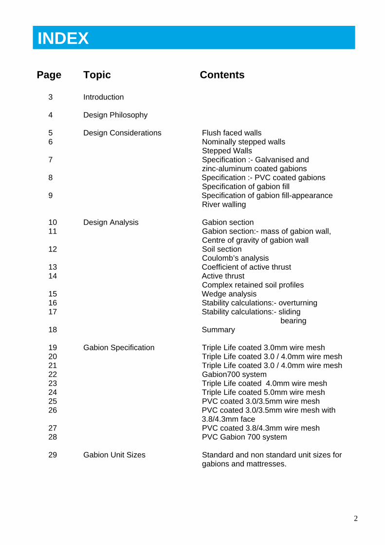
Page Topic Contents
3 Introduction
4 Design Philosophy
5 Design Considerations Flush faced walls 6 Nominally stepped walls
Stepped Walls 7 Specification :- Galvanised and
zinc-aluminum coated gabions 8 Specification :- PVC coated gabions
Specification of gabion fill 9 Specification of gabion fill-appearance
River walling
10 Design Analysis Gabion section 11 Gabion section:- mass of gabion wall,
Centre of gravity of gabion wall 12 Soil section
Coulomb’s analysis 13 Coefficient of active thrust 14 Active thrust
Complex retained soil profiles 15 Wedge analysis 16 Stability calculations:- overturning 17 Stability calculations:- sliding
bearing 18 Summary
19 Gabion Specification Triple Life coated 3.0mm wire mesh 20 Triple Life coated 3.0 / 4.0mm wire mesh 21 Triple Life coated 3.0 / 4.0mm wire mesh 22 Gabion700 system 23 Triple Life coated 4.0mm wire mesh 24 Triple Life coated 5.0mm wire mesh 25 PVC coated 3.0/3.5mm wire mesh 26 PVC coated 3.0/3.5mm wire mesh with
3.8/4.3mm face 27 PVC coated 3.8/4.3mm wire mesh 28 PVC Gabion 700 system
29 Gabion Unit Sizes Standard and non standard unit sizes for gabions and mattresses.
INDEX
3
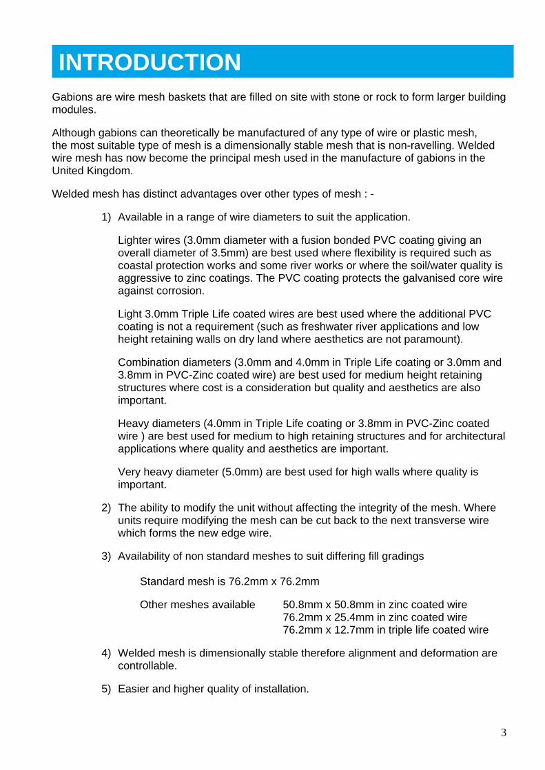
Gabions are wire mesh baskets that are filled on site with stone or rock to form larger building modules.
Although gabions can theoretically be manufactured of any type of wire or plastic mesh, the most suitable type of mesh is a dimensionally stable mesh that is non-ravelling. Welded wire mesh has now become the principal mesh used in the manufacture of gabions in the United Kingdom.
Welded mesh has distinct advantages over other types of mesh : -
1) Available in a range of wire diameters to suit the application.
Lighter wires (3.0mm diameter with a fusion bonded PVC coating giving an overall diameter of 3.5mm) are best used where flexibility is required such as coastal protection works and some river works or where the soil/water quality is aggressive to zinc coatings. The PVC coating protects the galvanised core wire against corrosion.
Light 3.0mm Triple Life coated wires are best used where the additional PVC coating is not a requirement (such as freshwater river applications and low height retaining walls on dry land where aesthetics are not paramount).
Combination diameters (3.0mm and 4.0mm in Triple Life coating or 3.0mm and 3.8mm in PVC-Zinc coated wire) are best used for medium height retaining structures where cost is a consideration but quality and aesthetics are also important.
Heavy diameters (4.0mm in Triple Life coating or 3.8mm in PVC-Zinc coated wire ) are best used for medium to high retaining structures and for architectural applications where quality and aesthetics are important.
Very heavy diameter (5.0mm) are best used for high walls where quality is important.
2) The ability to modify the unit without affecting the integrity of the mesh. Where units require modifying the mesh can be cut back to the next transverse wire which forms the new edge wire.
3) Availability of non standard meshes to suit differing fill gradings
Standard mesh is 76.2mm x 76.2mm
Other meshes available 50.8mm x 50.8mm in zinc coated wire 76.2mm x 25.4mm in zinc coated wire 76.2mm x 12.7mm in triple life coated wire
4) Welded mesh is dimensionally stable therefore alignment and deformation are controllable.
5) Easier and higher quality of installation.
INTRODUCTION
4
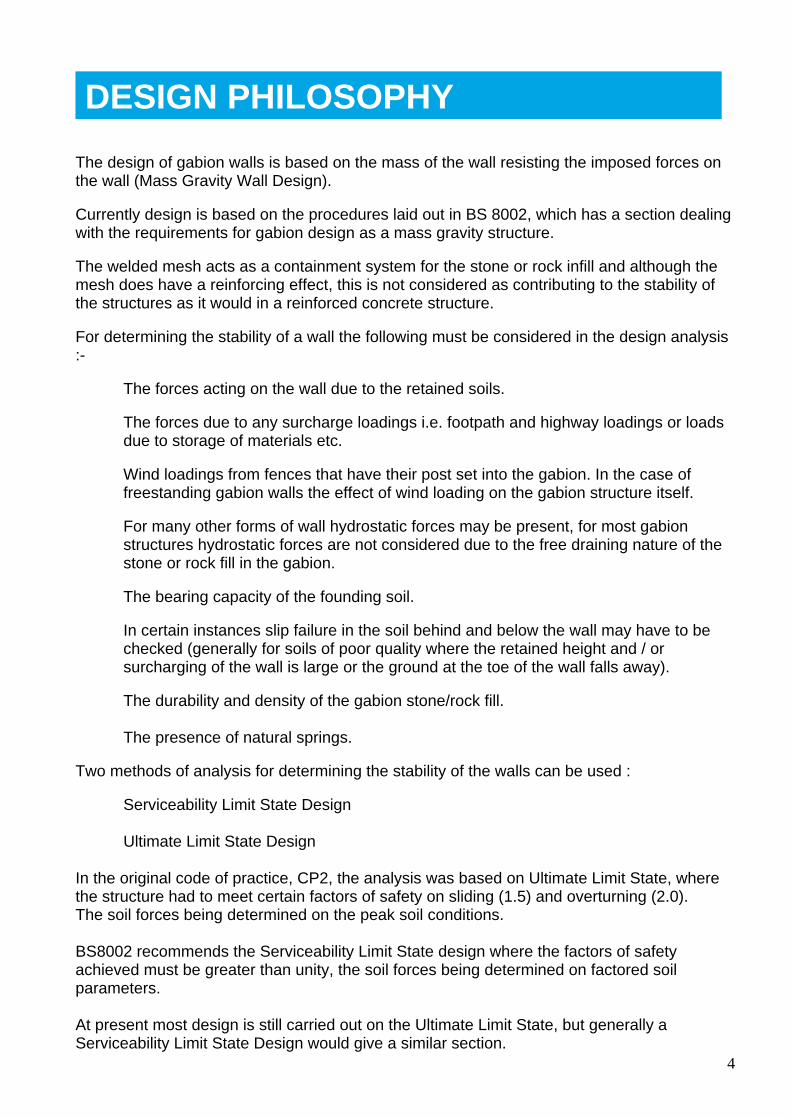
The design of gabion walls is based on the mass of the wall resisting the imposed forces on the wall (Mass Gravity Wall Design).
Currently design is based on the procedures laid out in BS 8002, which has a section dealing with the requirements for gabion design as a mass gravity structure.
The welded mesh acts as a containment system for the stone or rock infill and although the mesh does have a reinforcing effect, this is not considered as contributing to the stability of the structures as it would in a reinforced concrete structure.
For determining the stability of a wall the following must be considered in the design analysis :-
The forces acting on the wall due to the retained soils.
The forces due to any surcharge loadings i.e. footpath and highway loadings or loads due to storage of materials etc.
Wind loadings from fences that have their post set into the gabion. In the case of freestanding gabion walls the effect of wind loading on the gabion structure itself.
For many other forms of wall hydrostatic forces may be present, for most gabion structures hydrostatic forces are not considered due to the free draining nature of the stone or rock fill in the gabion.
The bearing capacity of the founding soil.
In certain instances slip failure in the soil behind and below the wall may have to be checked (generally for soils of poor quality where the retained height and / or surcharging of the wall is large or the ground at the toe of the wall falls away).
The durability and density of the gabion stone/rock fill.
The presence of natural springs.
Two methods of analysis for determining the stability of the walls can be used :
Serviceability Limit State Design
Ultimate Limit State Design
In the original code of practice, CP2, the analysis was based on Ultimate Limit State, where the structure had to meet certain factors of safety on sliding (1.5) and overturning (2.0). The soil forces being determined on the peak soil conditions.
BS8002 recommends the Serviceability Limit State design where the factors of safety achieved must be greater than unity, the soil forces being determined on factored soil parameters.
At present most design is still carried out on the Ultimate Limit State, but generally a Serviceability Limit State Design would give a similar section.
DESIGN PHILOSOPHY
5
When considering the gabion wall section required, thought must be given to the visual appearance of the wall :-
Flush faced walls :-
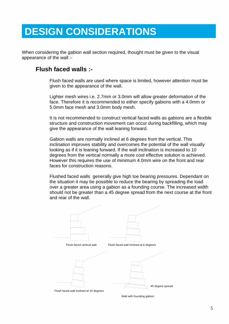
Flush faced walls are used where space is limited, however attention must be given to the appearance of the wall.
Lighter mesh wires i.e. 2.7mm or 3.0mm will allow greater deformation of the face. Therefore it is recommended to either specify gabions with a 4.0mm or 5.0mm face mesh and 3.0mm body mesh.
It is not recommended to construct vertical faced walls as gabions are a flexible structure and construction movement can occur during backfilling, which may give the appearance of the wall leaning forward.
Gabion walls are normally inclined at 6 degrees from the vertical. This inclination improves stability and overcomes the potential of the wall visually looking as if it is leaning forward. If the wall inclination is increased to 10 degrees from the vertical normally a more cost effective solution is achieved. However this requires the use of minimum 4.0mm wire on the front and rear faces for construction reasons.
Flushed faced walls generally give high toe bearing pressures. Dependant on the situation it may be possible to reduce the bearing by spreading the load over a greater area using a gabion as a founding course. The increased width should not be greater than a 45 degree spread from the next course at the front and rear of the wall.
Flush faced vertical wall Flush faced wall inclined at 6 degrees
Wall with founding gabion
Flush faced wall inclined at 10 degrees
45 degree spread
DESIGN CONSIDERATIONS
6
Nominal stepped walls :-
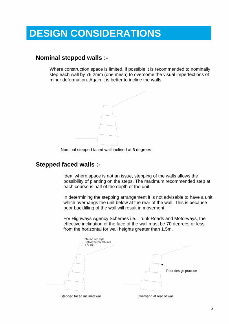
Where construction space is limited, if possible it is recommended to nominally step each wall by 76.2mm (one mesh) to overcome the visual imperfections of minor deformation. Again it is better to incline the walls.
Nominal stepped faced wall inclined at 6 degrees
Stepped faced walls :-
Ideal where space is not an issue, stepping of the walls allows the possibility of planting on the steps. The maximum recommended step at each course is half of the depth of the unit.
In determining the stepping arrangement it is not advisable to have a unit which overhangs the unit below at the rear of the wall. This is because poor backfilling of the wall will result in movement.
For Highways Agency Schemes i.e. Trunk Roads and Motorways, the effective inclination of the face of the wall must be 70 degrees or less from the horizontal for wall heights greater than 1.5m.
Stepped faced inclined wall
Effective face angleHighway agency schemes< 70 deg
Overhang at rear of wall
Poor design practice
DESIGN CONSIDERATIONS
7
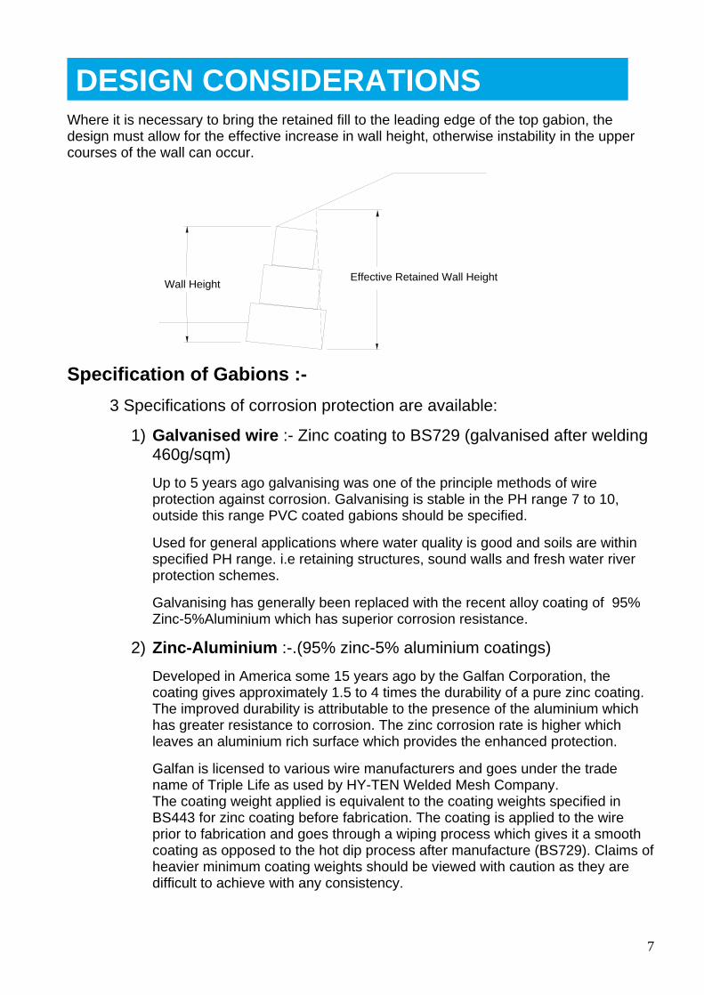
Where it is necessary to bring the retained fill to the leading edge of the top gabion, the design must allow for the effective increase in wall height, otherwise instability in the upper courses of the wall can occur.
Wall HeightEffective Retained Wall Height
Specification of Gabions :-
3 Specifications of corrosion protection are available:
1) Galvanised wire :- Zinc coating to BS729 (galvanised after welding 460g/sqm)
Up to 5 years ago galvanising was one of the principle methods of wire protection against corrosion. Galvanising is stable in the PH range 7 to 10, outside this range PVC coated gabions should be specified.
Used for general applications where water quality is good and soils are within specified PH range. i.e retaining structures, sound walls and fresh water river protection schemes.
Galvanising has generally been replaced with the recent alloy coating of 95% Zinc-5%Aluminium which has superior corrosion resistance.
2) Zinc-Aluminium :-.(95% zinc-5% aluminium coatings)
Developed in America some 15 years ago by the Galfan Corporation, the coating gives approximately 1.5 to 4 times the durability of a pure zinc coating. The improved durability is attributable to the presence of the aluminium which has greater resistance to corrosion. The zinc corrosion rate is higher which leaves an aluminium rich surface which provides the enhanced protection.
Galfan is licensed to various wire manufacturers and goes under the trade name of Triple Life as used by HY-TEN Welded Mesh Company. The coating weight applied is equivalent to the coating weights specified in BS443 for zinc coating before fabrication. The coating is applied to the wire prior to fabrication and goes through a wiping process which gives it a smooth coating as opposed to the hot dip process after manufacture (BS729). Claims of heavier minimum coating weights should be viewed with caution as they are difficult to achieve with any consistency.
DESIGN CONSIDERATIONS
8
PVC-zinc coatings
3) PVC coating was introduced as a protection to the core wire where pure galvanised coatings would be subject to rapid corrosion i.e saline water conditions or where the PH of the soil is outside the stable zone for zinc (stable zone for zinc is PH 7 to10). It is also used where gabions are subject to salt spray (trunk roads and motorways).
The PVC coating will give a life expectancy for the structure of up to 120 years providing that the PVC coating is not subjected to mechanical or chemical damage.
PVC coatings are generally available in green or grey, HY-TEN use green for 2 reasons:
Light coloured PVC coatings are less resilient to UV degradation.
Green is an environmentally accepted colour.
The PVC coating should be fusion bonded to the wire to prevent corrosion through capillary action. The term pressure bonding as applied to extruded coatings does not provide a true bond thereby enabling water ingress between the PVC coating and the core wire by capillary action.
Specification of Gabion Fill
The stability of a gabion wall is provided by the mass of the wall, the selection of filling materials must be considered in the design otherwise stability requirements may not be met.
Different types of fill have different densities.
Typical gabion bulk density values used in design are as follows:-
Flint rejects and whole stone 14.5 kN/cum Crushed Concrete 15 kN/cum Sandstone 15.5 kN/cum Limestone 16 kN/cum Granite 17 kN/cum Basalt 18 kN/cum Aggregate fill 16 kN/cum (geotextile lined units)
The gabion fill must be greater in size than the mesh so that all the fill is retained by the mesh, but not too large that large voids are present.
The normal grading of gabion fill is 100mm to 200mm although in certain instances the grading can be reduced to 80-150mm.
Selection of type of stone fill should be made on the visual appearance required and the availability of stone / rockfill locally.
DESIGN CONSIDERATIONS
9
Dry stone wall appearance
A blocky or angular rockfill where the rockfill to the face is hand placed, the bulk of the fill can be machine filled ensuring voids are minimised.
A flattish rock which is again hand placed (coursed), this type of rock is expensive and usually the bulk fill is of a cheaper stone or crushed concrete.
Random stone appearance
Generally a machine filled operation. The grading should be reduced to 80-150mm so that large voids are avoided which could result in settlement problems.
Whole stone or flint rejects are more fluid fills and bulging of the face can occur unless a heavier mesh is specified.
Aggregate-Rockfill
If an aggregate fill is used the unit should have a lined compartment to prevent loss of material finer than the standard mesh opening size. The unit also has a secondary facing cell usually 300mm wide filled with a rockfill of 100-200mm grading. Alternatively other meshes are available with small mesh openings, but check on the availability of wire diameters.
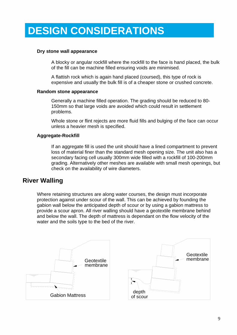
River Walling
Where retaining structures are along water courses, the design must incorporate protection against under scour of the wall. This can be achieved by founding the gabion wall below the anticipated depth of scour or by using a gabion mattress to provide a scour apron. All river walling should have a geotextile membrane behind and below the wall. The depth of mattress is dependant on the flow velocity of the water and the soils type to the bed of the river.
Geotextile membrane
Gabion Mattress
depthof scour
Geotextile membrane
DESIGN CONSIDERATIONS
10
Gabion Section
Although it is possible to develop a computer program to determine the optimum gabion section it is more usual to assume a section and modify it until the optimum section is achieved.
For the initial trial section a base width to height ratio can be assumed
0.4 to 0.5 for high frictional soils
0.5 to 0.7 for general type fill soils
0.7 to 1 for low frictional and cohesive soils
Traditionally gabions are available in various lengths for 1m or 1.5m widths and 0.5 and 1m heights. This gives a limited configuration of gabions to form the structure, generally wall heights and gabion course widths are in increments of 0.5m.
Bespoke design and manufacture has resulted in a greater range of course widths generally from 1m to 3m in approximate increments of 300mm. By utilising the greater range of unit widths more cost effective design can be achieved.
Developing this further we can offer the Gabion700 system which also gives potential for increments in height of approximately 300mm as well as 300mm increments in widths. The use of the Gabion700 system also improves the ease and quality of construction achievable.
Having determined the trial base width, the individual course widths can be decided based on the available unit widths. As previously stated the best gabion design is where the gabion fully bears down on the unit below (avoid gabions overhanging to the rear of the unit below in retaining structures).
DESIGN ANALYSIS
11
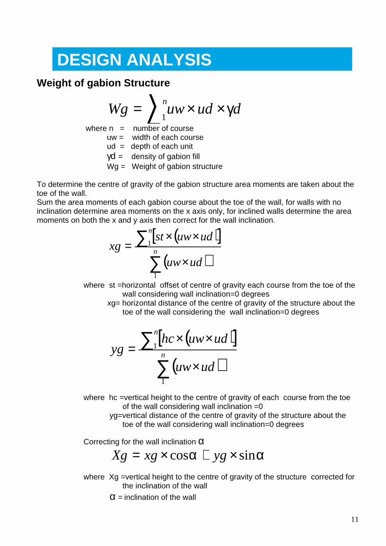
Weight of gabion Structure
∑ ××= nduduwWg
1γ
where n = number of course uw = width of each course ud = depth of each unit γd = density of gabion fill Wg = Weight of gabion structure
To determine the centre of gravity of the gabion structure area moments are taken about the toe of the wall. Sum the area moments of each gabion course about the toe of the wall, for walls with no inclination determine area moments on the x axis only, for inclined walls determine the area moments on both the x and y axis then correct for the wall inclination.
( )[ ]( )∑
∑×
××= n
n
uduw
uduwstxg
1
1
where st =horizontal offset of centre of gravity each course from the toe of the wall considering wall inclination=0 degrees
xg= horizontal distance of the centre of gravity of the structure about the toe of the wall considering the wall inclination=0 degrees
( )[ ]( )∑
∑×
××= n
n
uduw
uduwhcyg
1
1
where hc =vertical height to the centre of gravity of each course from the toe of the wall considering wall inclination =0
yg=vertical distance of the centre of gravity of the structure about the toe of the wall considering wall inclination=0 degrees
Correcting for the wall inclination α
αα sincos ×+×= ygxgXg
where Xg =vertical height to the centre of gravity of the structure corrected for the inclination of the wall
α = inclination of the wall
DESIGN ANALYSIS
12
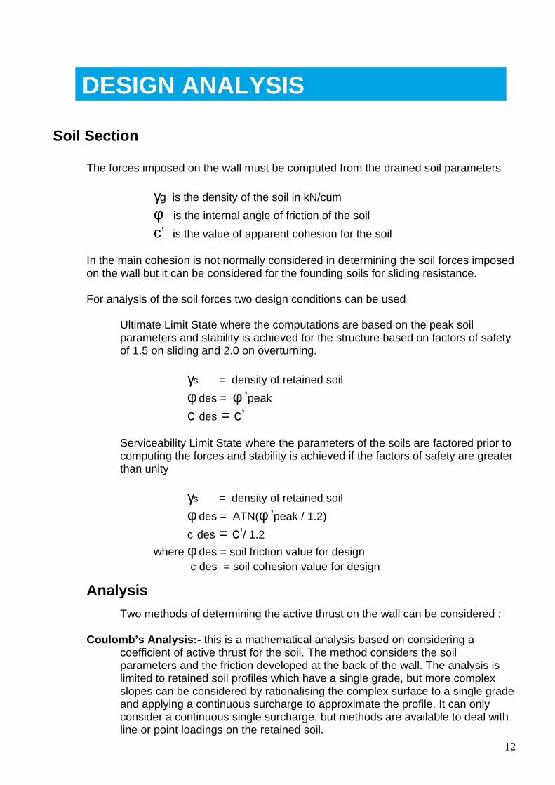
Soil Section
The forces imposed on the wall must be computed from the drained soil parameters
γg is the density of the soil in kN/cum
φ‘ is the internal angle of friction of the soil
c’ is the value of apparent cohesion for the soil
In the main cohesion is not normally considered in determining the soil forces imposed on the wall but it can be considered for the founding soils for sliding resistance.
For analysis of the soil forces two design conditions can be used
Ultimate Limit State where the computations are based on the peak soil parameters and stability is achieved for the structure based on factors of safety of 1.5 on sliding and 2.0 on overturning.
γs = density of retained soil
φ des = φ ’peak
c des = c’
Serviceability Limit State where the parameters of the soils are factored prior to computing the forces and stability is achieved if the factors of safety are greater than unity
γs = density of retained soil
φ des = ATN(φ ’peak / 1.2)
c des = c’/ 1.2 where φ des = soil friction value for design
c des = soil cohesion value for design
Analysis
Two methods of determining the active thrust on the wall can be considered :
Coulomb’s Analysis:- this is a mathematical analysis based on considering a coefficient of active thrust for the soil. The method considers the soil parameters and the friction developed at the back of the wall. The analysis is limited to retained soil profiles which have a single grade, but more complex slopes can be considered by rationalising the complex surface to a single grade and applying a continuous surcharge to approximate the profile. It can only consider a continuous single surcharge, but methods are available to deal with line or point loadings on the retained soil.
DESIGN ANALYSIS
13
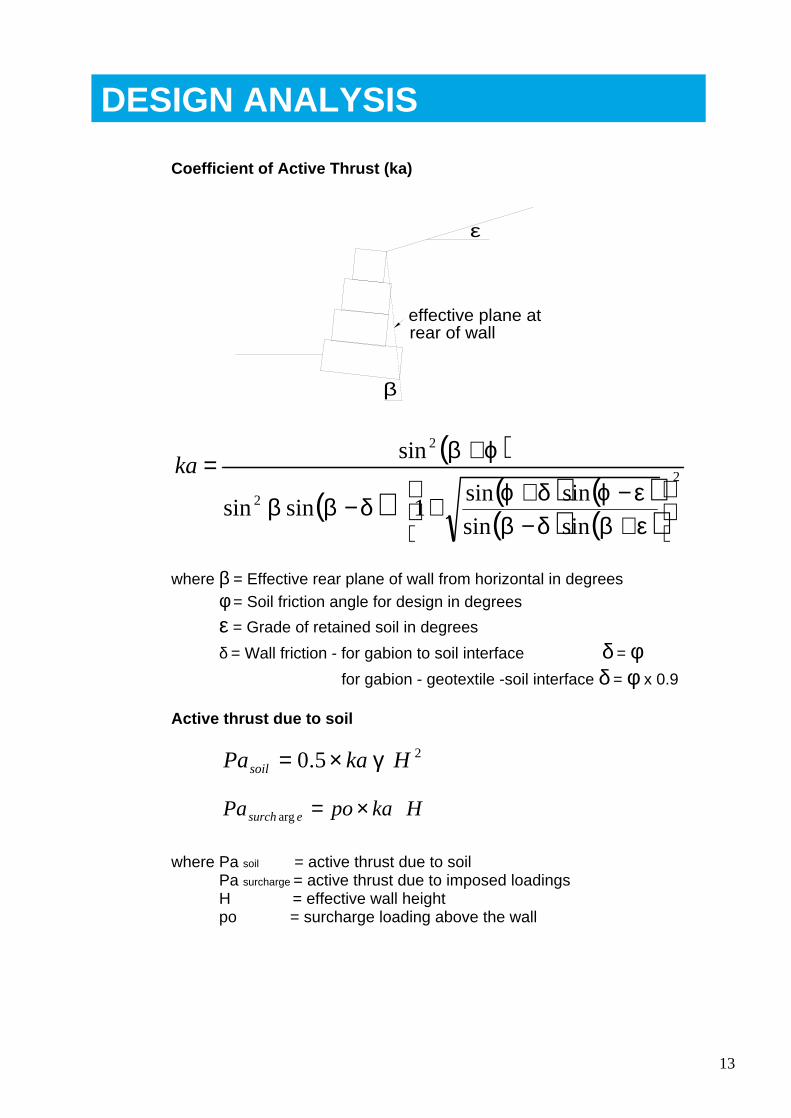
Coefficient of Active Thrust (ka)
ε
β
effective plane at rear of wall
( )
( ) ( ) ( )( ) ( )
2
2
2
sinsin
sinsin1sinsin
sin
+−−++−
+=
εβδβεϕδϕδββ
ϕβka
where β = Effective rear plane of wall from horizontal in degrees φ = Soil friction angle for design in degrees
ε = Grade of retained soil in degrees
δ = Wall friction - for gabion to soil interface δ = φ for gabion - geotextile -soil interface δ = φ x 0.9
Active thrust due to soil
25.0 HkaPasoil γ×= HkapoPa esurch ×=arg
where Pa soil = active thrust due to soil Pa surcharge = active thrust due to imposed loadings H = effective wall height po = surcharge loading above the wall
DESIGN ANALYSIS
14
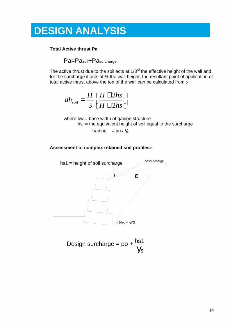
Total Active thrust Pa
Pa=Pasoil+Pasurcharge
The active thrust due to the soil acts at 1/3rd the effective height of the wall and for the surcharge it acts at ½ the wall height, the resultant point of application of total active thrust above the toe of the wall can be calculated from :-
++=
hsH
hsHHdhsoil 2
3
3
where bw = base width of gabion structure hs = the equivalent height of soil equal to the surcharge
loading = po / γs
Assessment of complex retained soil profiles:-
ε
45deg + φ/2
hs1 = height of soil surcharge po=surcharge
Design surcharge = po + γs
hs1
DESIGN ANALYSIS
15
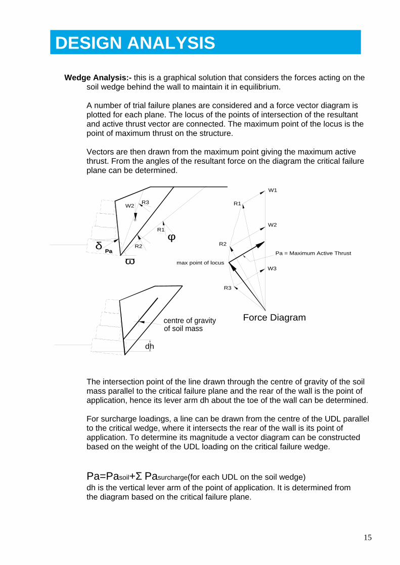
Wedge Analysis:- this is a graphical solution that considers the forces acting on the soil wedge behind the wall to maintain it in equilibrium.
A number of trial failure planes are considered and a force vector diagram is plotted for each plane. The locus of the points of intersection of the resultant and active thrust vector are connected. The maximum point of the locus is the point of maximum thrust on the structure.
Vectors are then drawn from the maximum point giving the maximum active thrust. From the angles of the resultant force on the diagram the critical failure plane can be determined.
ωδ
φR2
R3
R2Pa Pa = Maximum Active ThrustPa
W2 R1
R3
R1
W1
W2
W3max point of locus
Force Diagram
dh
centre of gravity of soil mass
The intersection point of the line drawn through the centre of gravity of the soil mass parallel to the critical failure plane and the rear of the wall is the point of application, hence its lever arm dh about the toe of the wall can be determined.
For surcharge loadings, a line can be drawn from the centre of the UDL parallel to the critical wedge, where it intersects the rear of the wall is its point of application. To determine its magnitude a vector diagram can be constructed based on the weight of the UDL loading on the critical failure wedge.
Pa=Pasoil+Σ Pasurcharge(for each UDL on the soil wedge) dh is the vertical lever arm of the point of application. It is determined from the diagram based on the critical failure plane.
DESIGN ANALYSIS
16
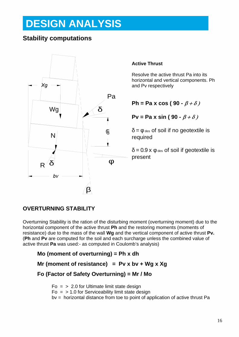
Stability computations
δ
β
Pa
Wg
δR
N
φ
OVERTURNING STABILITY
Overturning Stability is the ration of the disturbing moment (overturning moment) due to the horizontal component of the active thrust Ph and the restoring moments (moments of resistance) due to the mass of the wall Wg and the vertical component of active thrust Pv. (Ph and Pv are computed for the soil and each surcharge unless the combined value of active thrust Pa was used:- as computed in Coulomb’s analysis)
Mo (moment of overturning) = Ph x dh
Mr (moment of resistance) = Pv x bv + Wg x Xg
Fo (Factor of Safety Overturning) = Mr / Mo
Fo = > 2.0 for Ultimate limit state design Fo = > 1.0 for Serviceability limit state design bv = horizontal distance from toe to point of application of active thrust Pa
Active Thrust
Resolve the active thrust Pa into its horizontal and vertical components. Ph
and Pv respectively
Ph = Pa x cos ( 90 -
Pv = Pa x sin ( 90 -
δ = φ des of soil if no geotextile is required
δ = 0.9 x φ des of soil if geotextile is present
DESIGN ANALYSIS
17
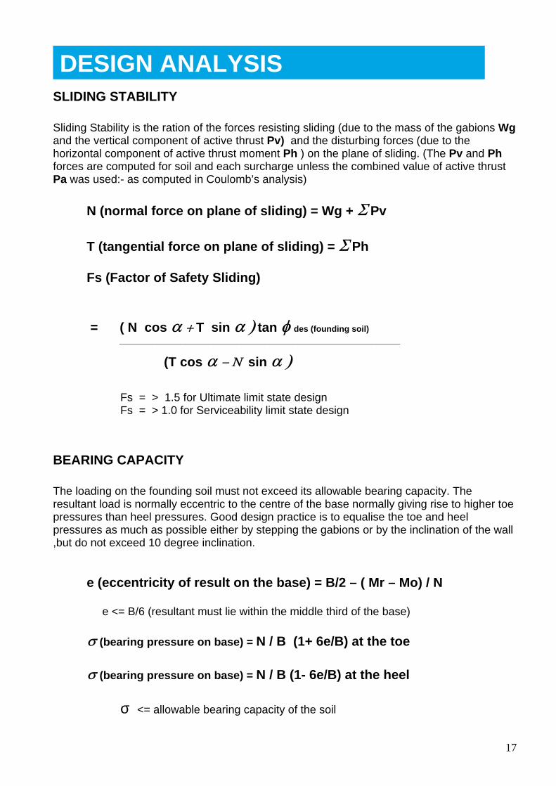
SLIDING STABILITY
Sliding Stability is the ration of the forces resisting sliding (due to the mass of the gabions Wg and the vertical component of active thrust Pv) and the disturbing forces (due to the horizontal component of active thrust moment Ph ) on the plane of sliding. (The Pv and Ph forces are computed for soil and each surcharge unless the combined value of active thrust Pa was used:- as computed in Coulomb’s analysis)
N (normal force on plane of sliding) = Wg + Pv
T (tangential force on plane of sliding) = Ph
Fs (Factor of Safety Sliding)
= ( N cos T sin tan des (founding soil) ____________________________________________________________
(T cos sin
Fs = > 1.5 for Ultimate limit state design Fs = > 1.0 for Serviceability limit state design
BEARING CAPACITY
The loading on the founding soil must not exceed its allowable bearing capacity. The resultant load is normally eccentric to the centre of the base normally giving rise to higher toe pressures than heel pressures. Good design practice is to equalise the toe and heel pressures as much as possible either by stepping the gabions or by the inclination of the wall ,but do not exceed 10 degree inclination.
e (eccentricity of result on the base) = B/2 – ( Mr – Mo) / N
e <= B/6 (resultant must lie within the middle third of the base)
(bearing pressure on base) = N / B (1+ 6e/B) at the toe
(bearing pressure on base) = N / B (1- 6e/B) at the heel
σ <= allowable bearing capacity of the soil
DESIGN ANALYSIS
18
Summary
The design must be checked at each gabion course to ensure stability is achieved throughout the structure (consider the gabion at the level being checked to be the first course and analyse for the wall height above). When checking the factor of safety against sliding on the gabion to gabion interface, the phi value is taken as 35 degrees.
The factor of safety on sliding can be improved by founding the gabion on a granular sub base or a concrete foundation of minimum 300mm depth. However this should not be considered unless the factor of safety on sliding, based on the sub soil, is equal or greater than 1.3.
In very poor soils, to achieve satisfactory stability it may be necessary to fully cut back the retained fill to a slope of maximum 45 degrees and replace with a granular material. The design can then be based on a retained granular fill. The requirement for cutting back the slope should be well defined on the tender drawings and in the specification.
The design analysis will only be correct if the soil parameters used in the design are representative to the soils on site. The soil parameters used for design should be based on factual soil investigation (preferably drained parameters) in the locality of the structure.
Where factual information is not readily available values of typical soil parameters for various soils are given in BS8002 together with correlations between plasticity index and standard penetration tests to soil friction values.
For good design in retaining structures the gabion should fully bear on the unit below.
HY-TEN Gabion Solutions will be pleased to carry out a design evaluation as part of out Technical Support Service.
Contact:- R D Farmer Technical Manager Tel / Fax 01245 426661 Mob 07803 938844 e-mail [email protected]
Web Site www.hy-tengabions.com
This design guide is to assist engineers in carrying out gabion retaining wall design.
No liability is accepted by HY-TEN Gabion Solutions or its employees with respect to errors or omissions in this guide. It is the responsibility of the user to satisfy themselves that the analysis outlined is correct.
DESIGN ANALYSIS
19
3.0mm wire diameter
Gabions shall comply with the following specifications
MANUFACTURE Gabions shall be manufactured from a hard drawn steel wire formed into a bi-axial mesh grid by electrically welding the cross wires at every intersection.
Gabions:-to be factory assembled with stainless steel clips connecting side panels and diaphragms to the base panel.
MESH SIZE Mesh openings shall be square of nominal dimension of 76.2mm on the grid.
MESH WIRE Nominal wire diameter shall be 3.0mm to BS 1052.
CORROSION Wire shall be triple life (95% Zinc 5% Aluminium) coated. PROTECTION
JOINTING Gabions shall be provided with lacing wire for site assembly. Lacing wire shall be of minimum wire diameter 2.2mm (all in accordance with the corrosion specified) for final jointing.
ROCKFILL Gabion fill shall be a hard durable and non frost susceptible (rock or stone type) having a minimum dimension not less than the mesh opening and a maximum dimension of 200mm.
CONSTRUCTION All rockfill shall be packed tightly to minimize voids and the rockfill on the exposed face of the gabion is to be hand packed.
Internal windlass bracing ties 2 per 1sqm at 1/3rd points vertically and mid point horizontally on 1m deep units and at mid height and mid point horizontally on 0.5m deep units.
Adjacent units to be jointed by continuous lacing on the vertical and to the horizontal joints at front and rear of coursing joints.
Units shall be filled such that the mesh lid bears onto the rock fill. The lid shall be wired down on all joints and across the diaphragms.
GABION SPECIFICATION
20
3.0mm with 4.0mm wire diameter on face panels
Gabions shall comply with the following specifications
MANUFACTURE Gabions shall be manufactured from a hard drawn steel wire formed into a bi-axial mesh grid by electrically welding the cross wires at every intersection.
Gabions:-to be factory assembled with stainless steel clips connecting side panels and diaphragms to the base panel.
MESH SIZE Mesh openings shall be square of nominal dimension of 76.2mm on the grid.
MESH WIRE Nominal wire diameter shall be 3.0mm for the body of the gabion and 4.0mm for the exposed face mesh all, to BS 1052
CORROSION Wire shall be triple life (95% Zinc 5% Aluminium) coated. PROTECTION
JOINTING Gabions shall be provided with lacing wire for site assembly. Lacing wire shall be of minimum wire diameter 2.2mm (all in accordance with the corrosion specified) for final jointing.
ROCKFILL Gabion fill shall be a hard durable and non frost susceptible (rock or stone type) having a minimum dimension not less than the mesh opening and a maximum dimension of 200mm.
CONSTRUCTION All rockfill shall be packed tightly to minimize voids and the rockfill on the exposed face of the gabion is to be hand packed.
Internal windlass bracing ties 2 per 1sqm at 1/3rd points vertically and mid point horizontally on 1m deep units and at mid height and mid point horizontally on 0.5m deep units.
Adjacent units to be jointed by continuous lacing on the vertical and to the horizontal joints at front and rear of coursing joints
Units shall be filled such that the mesh lid bears onto the rock fill. The lid shall be wired down on all joints and across the diaphragms.
GABION SPECIFICATION
21
3.0mm with 4.0mm wire diameter on face and rear panels
Gabions shall comply with the following specifications
MANUFACTURE Gabions shall be manufactured from a hard drawn steel wire formed into a bi-axial mesh grid by electrically welding the cross wires at every intersection.
Gabions:-to be factory assembled with stainless steel clips connecting side panels and diaphragms to the base panel.
MESH SIZE Mesh opening shall be square of nominal dimension of 76.2mm on the grid.
MESH WIRE Nominal wire diameter shall be 3.0mm for the body of the gabion and 4.0mm for the exposed face mesh and rear mesh panel, all to BS 1052
CORROSION Wire shall be triple life (95% Zinc 5% Aluminium) coated. PROTECTION
JOINTING Gabions shall be provided with lacing wire for site assembly. Lacing wire shall be of minimum wire diameter 2.2mm (all in accordance with the corrosion specified) for final jointing.
ROCKFILL Gabion fill shall be a hard durable and non frost susceptible (rock or stone type) having a minimum dimension not less than the mesh opening and a maximum dimension of 200mm.
CONSTRUCTION All rockfill shall be packed tightly to minimize voids and the rockfill on the exposed face of the gabion is to be hand packed.
Internal windlass bracing ties 2 per 1sqm at 1/3rd points vertically and mid point horizontally on 1m deep units and at mid height and mid point horizontally on 0.5m deep units.
Adjacent units to be jointed by continuous lacing on the vertical and to the horizontal joints at front and rear of coursing joints.
Units shall be filled such that the mesh lid bears onto the rock fill. The lid shall be wired down on all joints and across the diaphragms.
GABION SPECIFICATION
22
Gabion700 system
Gabions shall comply with the following specifications
MANUFACTURE Gabions shall be manufactured from a hard drawn steel wire formed into a bi-axial mesh grid by electrically welding the cross wires at every intersection.
Gabions:-to be factory assembled with stainless steel clips connecting side panels and diaphragms to the base panel.
MESH SIZE Mesh openings shall be square of nominal dimension of 76.2mm on the grid.
MESH WIRE Nominal wire diameter shall be 3.0mm for the body of the gabion and 4.0mm for the exposed face mesh and rear mesh panel, all to BS 1052
DIAPHRAGMS Diaphragms are to be a maximum of 700mm between centres on the exposed faces of the gabions.
DEFORMATION The maximum deformation coefficient is to be 0.25 for the CO-EFFICIENT unsupported mesh facing.
CORROSION Wire shall be triple life (95% Zinc 5% Aluminium) coated. PROTECTION
JOINTING Gabions shall be provided with helicals of minimum 3.0mm wire diameter for vertical joints and lacing wire / helicals for horizontal joints. Lacing wire shall be of minimum wire diameter 2.2mm (all in accordance with the corrosion specified) for final jointing.
ROCKFILL Gabion fill shall be a hard durable and non frost susceptible (rock or stone type) having a minimum dimension not less than the mesh opening and a maximum dimension of 200mm.
CONSTRUCTION All rockfill shall be packed tightly to minimize voids and the rockfill on the exposed face of the gabion is to be hand packed.
Internal windlass bracing ties (formed from the lacing wire) 2 per 1sqm at 1/3rd points vertically and mid point horizontally on 1m deep units and at mid height and mid point horizontally on 0.7m deep units.
Units shall be filled such that the mesh lid bears onto the rock fill. The lid shall be wired down on all joints and across the diaphragms.
GABION SPECIFICATION
23
4.0mm wire diameter
Gabions shall comply with the following specifications
MANUFACTURE Gabions shall be manufactured from a hard drawn steel wire formed into a bi-axial mesh grid by electrically welding the cross wires at every intersection.
Gabions:-to be factory assembled with stainless steel clips connecting side panels and diaphragms to the base panel.
MESH SIZE Mesh openings shall be square of nominal dimension of 76.2mm on the grid.
MESH WIRE Nominal wire diameter shall be 4.0mm to BS 1052
CORROSION Wire shall be triple life (95% Zinc 5% Aluminium) coated. PROTECTION
JOINTING Gabions shall be provided with lacing wire for site assembly. Lacing wire shall be wire of minimum diameter 2.2mm (all in accordance with the corrosion specified) for final jointing.
ROCKFILL Gabion fill shall be a hard durable and non frost susceptible (rock or stone type) having a minimum dimension not less than the mesh opening and a maximum dimension of 200mm.
CONSTRUCTION All rockfill shall be packed tightly to minimize voids and the rockfill on the exposed face of the gabion is to be hand packed.
Internal windlass bracing ties 2 per 1sqm at 1/3rd points vertically and mid point horizontally on 1m deep units and at mid height and mid point horizontally on 0.5m deep units.
Adjacent units to be jointed by continuous lacing on the vertical and to the horizontal joints at front and rear of coursing joints.
Units shall be filled such that the mesh lid bears onto the rock fill. The lid shall be wired down on all joints and across the diaphragms.
GABION SPECIFICATION
24
5.0mm wire diameter
Gabions shall comply with the following specifications
MANUFACTURE Gabions shall be manufactured from a hard drawn steel wire formed into a bi-axial mesh grid by electrically welding the cross wires at every intersection.
Gabions:-to be factory assembled with stainless steel clips connecting side panels and diaphragms to the base panel.
MESH SIZE Mesh openings shall be square of nominal dimension of 76.2mm on the grid.
MESH WIRE Nominal wire diameter shall be 5.0mm to BS 1052
CORROSION Wire shall be triple life (95% Zinc 5% Aluminium) coated. PROTECTION
JOINTING Gabions shall be provided with lacing wire for site assembly. Lacing wire shall be of minimum diameter 2.2mm (all in accordance with the corrosion specified) for final jointing.
ROCKFILL Gabion fill shall be a hard durable and non frost susceptible (rock or stone type) having a minimum dimension not less than the mesh opening and a maximum dimension of 200mm.
CONSTRUCTION All rockfill shall be packed tightly to minimize voids and the rockfill on the exposed face of the gabion is to be hand packed.
Internal windlass bracing ties 2 per 1sqm at 1/3rd points vertically and mid point horizontally on 1m deep units and at mid height and mid point horizontally on 0.5m deep units.
Adjacent units to be jointed by continuous lacing on vertical and to the horizontal joints at front and rear of coursing joints.
Units shall be filled such that the mesh lid bears onto the rock fill. The lid shall be wired down on all joints and across the diaphragms.
GABION SPECIFICATION
25
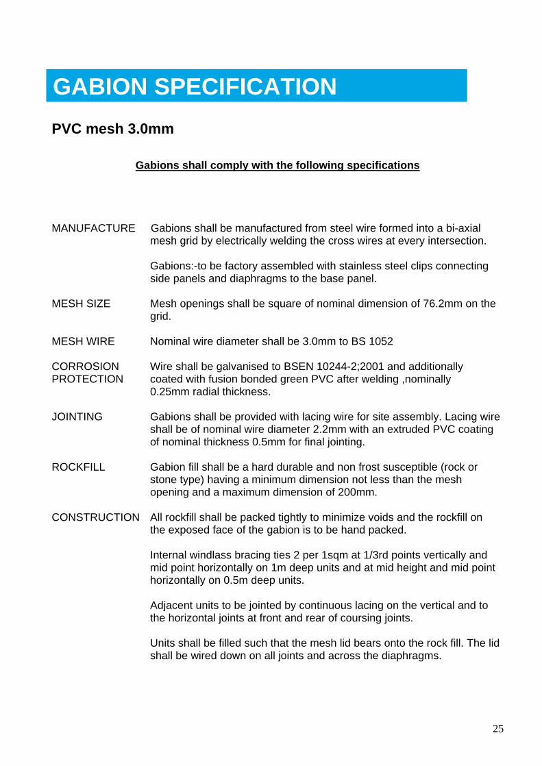
PVC mesh 3.0mm
Gabions shall comply with the following specifications
MANUFACTURE Gabions shall be manufactured from steel wire formed into a bi-axial mesh grid by electrically welding the cross wires at every intersection.
Gabions:-to be factory assembled with stainless steel clips connecting side panels and diaphragms to the base panel.
MESH SIZE Mesh openings shall be square of nominal dimension of 76.2mm on the grid.
MESH WIRE Nominal wire diameter shall be 3.0mm to BS 1052
CORROSION Wire shall be galvanised to BSEN 10244-2;2001 and additionally PROTECTION coated with fusion bonded green PVC after welding ,nominally
0.25mm radial thickness.
JOINTING Gabions shall be provided with lacing wire for site assembly. Lacing wire shall be of nominal wire diameter 2.2mm with an extruded PVC coating of nominal thickness 0.5mm for final jointing.
ROCKFILL Gabion fill shall be a hard durable and non frost susceptible (rock or stone type) having a minimum dimension not less than the mesh opening and a maximum dimension of 200mm.
CONSTRUCTION All rockfill shall be packed tightly to minimize voids and the rockfill on the exposed face of the gabion is to be hand packed.
Internal windlass bracing ties 2 per 1sqm at 1/3rd points vertically and mid point horizontally on 1m deep units and at mid height and mid point horizontally on 0.5m deep units.
Adjacent units to be jointed by continuous lacing on the vertical and to the horizontal joints at front and rear of coursing joints.
Units shall be filled such that the mesh lid bears onto the rock fill. The lid shall be wired down on all joints and across the diaphragms.
GABION SPECIFICATION
26
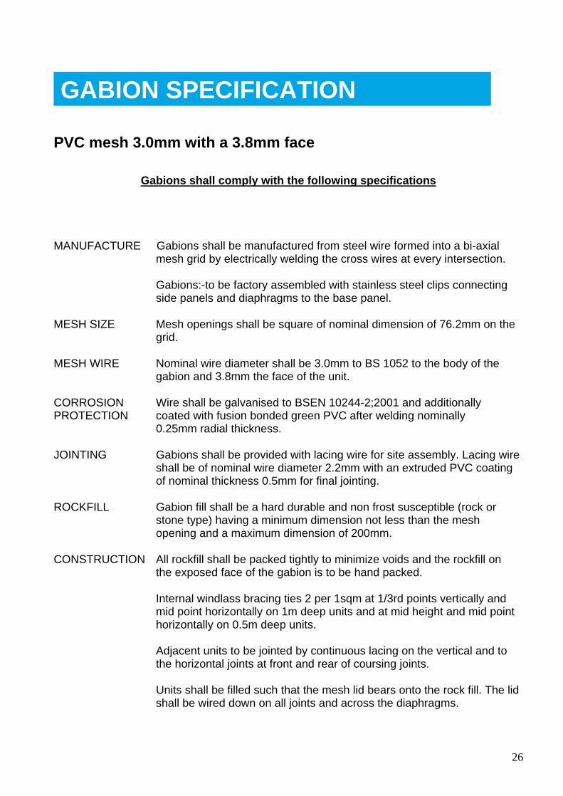
PVC mesh 3.0mm with a 3.8mm face
Gabions shall comply with the following specifications
MANUFACTURE Gabions shall be manufactured from steel wire formed into a bi-axial mesh grid by electrically welding the cross wires at every intersection.
Gabions:-to be factory assembled with stainless steel clips connecting side panels and diaphragms to the base panel.
MESH SIZE Mesh openings shall be square of nominal dimension of 76.2mm on the grid.
MESH WIRE Nominal wire diameter shall be 3.0mm to BS 1052 to the body of the gabion and 3.8mm the face of the unit.
CORROSION Wire shall be galvanised to BSEN 10244-2;2001 and additionally PROTECTION coated with fusion bonded green PVC after welding nominally
0.25mm radial thickness.
JOINTING Gabions shall be provided with lacing wire for site assembly. Lacing wire shall be of nominal wire diameter 2.2mm with an extruded PVC coating of nominal thickness 0.5mm for final jointing.
ROCKFILL Gabion fill shall be a hard durable and non frost susceptible (rock or stone type) having a minimum dimension not less than the mesh opening and a maximum dimension of 200mm.
CONSTRUCTION All rockfill shall be packed tightly to minimize voids and the rockfill on the exposed face of the gabion is to be hand packed.
Internal windlass bracing ties 2 per 1sqm at 1/3rd points vertically and mid point horizontally on 1m deep units and at mid height and mid point horizontally on 0.5m deep units.
Adjacent units to be jointed by continuous lacing on the vertical and to the horizontal joints at front and rear of coursing joints.
Units shall be filled such that the mesh lid bears onto the rock fill. The lid shall be wired down on all joints and across the diaphragms.
GABION SPECIFICATION
27
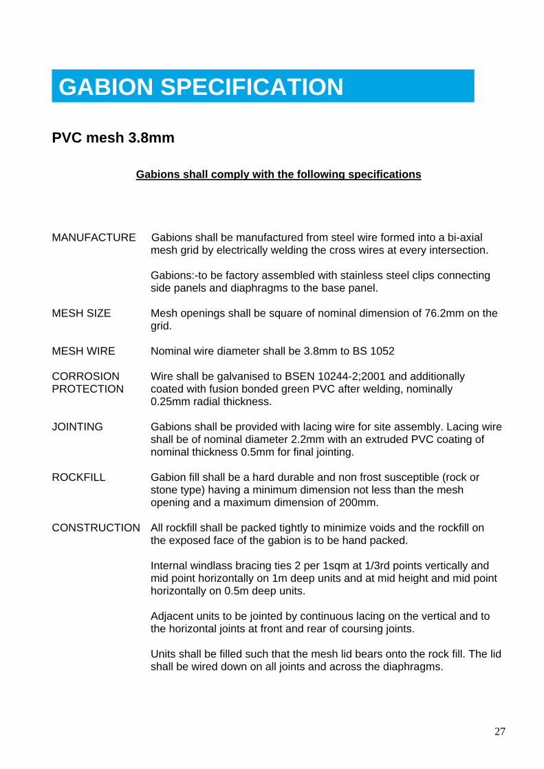
PVC mesh 3.8mm
Gabions shall comply with the following specifications
MANUFACTURE Gabions shall be manufactured from steel wire formed into a bi-axial mesh grid by electrically welding the cross wires at every intersection.
Gabions:-to be factory assembled with stainless steel clips connecting side panels and diaphragms to the base panel.
MESH SIZE Mesh openings shall be square of nominal dimension of 76.2mm on the grid.
MESH WIRE Nominal wire diameter shall be 3.8mm to BS 1052
CORROSION Wire shall be galvanised to BSEN 10244-2;2001 and additionally PROTECTION coated with fusion bonded green PVC after welding, nominally
0.25mm radial thickness.
JOINTING Gabions shall be provided with lacing wire for site assembly. Lacing wire shall be of nominal diameter 2.2mm with an extruded PVC coating of nominal thickness 0.5mm for final jointing.
ROCKFILL Gabion fill shall be a hard durable and non frost susceptible (rock or stone type) having a minimum dimension not less than the mesh opening and a maximum dimension of 200mm.
CONSTRUCTION All rockfill shall be packed tightly to minimize voids and the rockfill on the exposed face of the gabion is to be hand packed.
Internal windlass bracing ties 2 per 1sqm at 1/3rd points vertically and mid point horizontally on 1m deep units and at mid height and mid point horizontally on 0.5m deep units.
Adjacent units to be jointed by continuous lacing on the vertical and to the horizontal joints at front and rear of coursing joints.
Units shall be filled such that the mesh lid bears onto the rock fill. The lid shall be wired down on all joints and across the diaphragms.
GABION SPECIFICATION
28
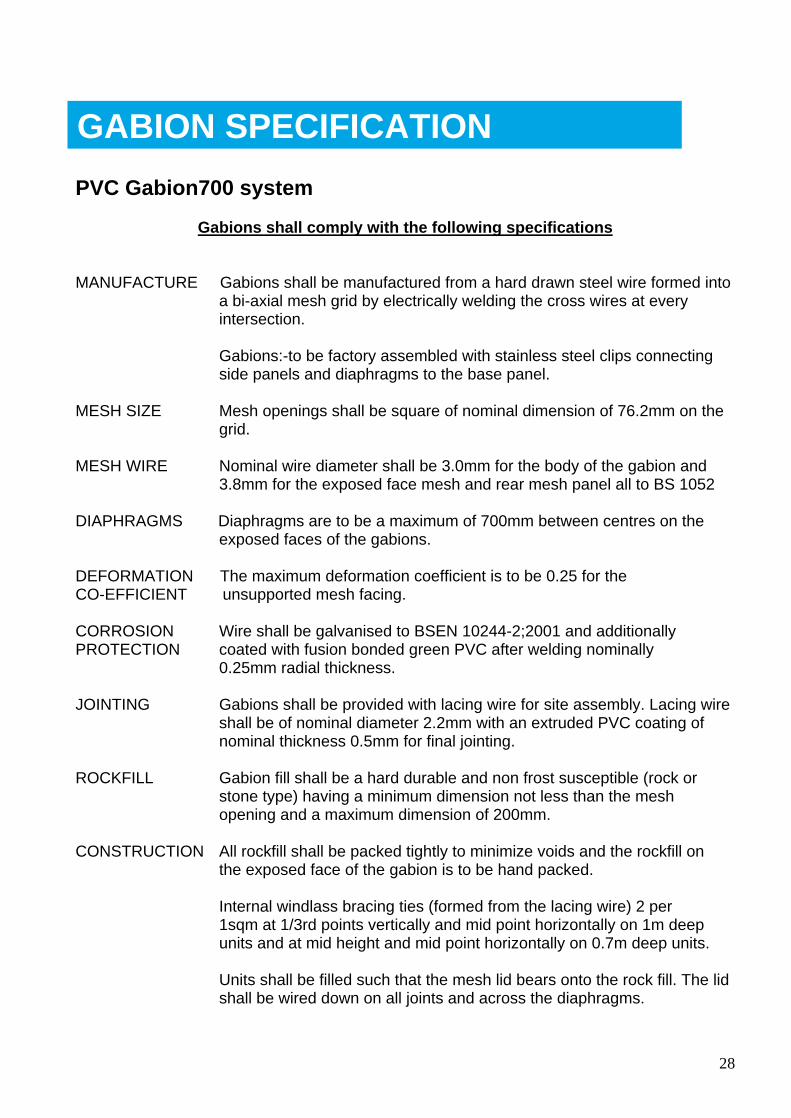
PVC Gabion700 system
Gabions shall comply with the following specifications
MANUFACTURE Gabions shall be manufactured from a hard drawn steel wire formed into a bi-axial mesh grid by electrically welding the cross wires at every intersection.
Gabions:-to be factory assembled with stainless steel clips connecting side panels and diaphragms to the base panel.
MESH SIZE Mesh openings shall be square of nominal dimension of 76.2mm on the grid.
MESH WIRE Nominal wire diameter shall be 3.0mm for the body of the gabion and 3.8mm for the exposed face mesh and rear mesh panel all to BS 1052
DIAPHRAGMS Diaphragms are to be a maximum of 700mm between centres on the exposed faces of the gabions.
DEFORMATION The maximum deformation coefficient is to be 0.25 for the CO-EFFICIENT unsupported mesh facing.
CORROSION Wire shall be galvanised to BSEN 10244-2;2001 and additionally PROTECTION coated with fusion bonded green PVC after welding nominally
0.25mm radial thickness.
JOINTING Gabions shall be provided with lacing wire for site assembly. Lacing wire shall be of nominal diameter 2.2mm with an extruded PVC coating of nominal thickness 0.5mm for final jointing.
ROCKFILL Gabion fill shall be a hard durable and non frost susceptible (rock or stone type) having a minimum dimension not less than the mesh opening and a maximum dimension of 200mm.
CONSTRUCTION All rockfill shall be packed tightly to minimize voids and the rockfill on the exposed face of the gabion is to be hand packed.
Internal windlass bracing ties (formed from the lacing wire) 2 per 1sqm at 1/3rd points vertically and mid point horizontally on 1m deep units and at mid height and mid point horizontally on 0.7m deep units.
Units shall be filled such that the mesh lid bears onto the rock fill. The lid shall be wired down on all joints and across the diaphragms.
GABION SPECIFICATION
29
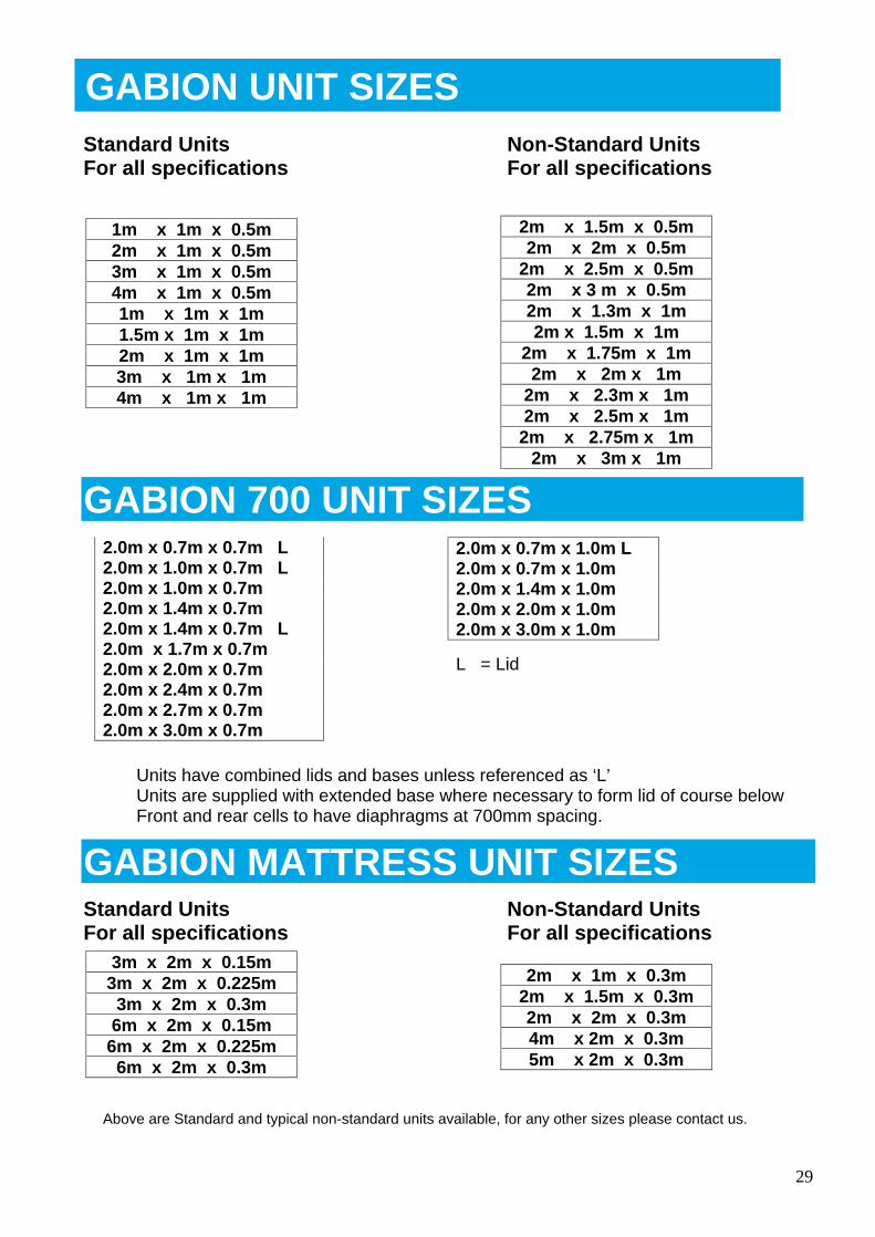
Standard Units Non-Standard Units For all specifications For all specifications
GABION 700 UNIT SIZES
Units have combined lids and bases unless referenced as ‘L’ Units are supplied with extended base where necessary to form lid of course below Front and rear cells to have diaphragms at 700mm spacing.
GABION MATTRESS UNIT SIZES Standard Units Non-Standard Units For all specifications For all specifications
WELDED ESH COMPANY
1m x 1m x 0.5m 2m x 1m x 0.5m 3m x 1m x 0.5m 4m x 1m x 0.5m 1m x 1m x 1m 1.5m x 1m x 1m 2m x 1m x 1m 3m x 1m x 1m 4m x 1m x 1m
2m x 1.5m x 0.5m 2m x 2m x 0.5m
2m x 2.5m x 0.5m 2m x 3 m x 0.5m 2m x 1.3m x 1m 2m x 1.5m x 1m
2m x 1.75m x 1m 2m x 2m x 1m
2m x 2.3m x 1m 2m x 2.5m x 1m 2m x 2.75m x 1m
2m x 3m x 1m
3m x 2m x 0.15m 3m x 2m x 0.225m 3m x 2m x 0.3m 6m x 2m x 0.15m 6m x 2m x 0.225m 6m x 2m x 0.3m
2m x 1m x 0.3m 2m x 1.5m x 0.3m 2m x 2m x 0.3m 4m x 2m x 0.3m 5m x 2m x 0.3m
2.0m x 0.7m x 0.7m L 2.0m x 1.0m x 0.7m L 2.0m x 1.0m x 0.7m 2.0m x 1.4m x 0.7m 2.0m x 1.4m x 0.7m L 2.0m x 1.7m x 0.7m 2.0m x 2.0m x 0.7m 2.0m x 2.4m x 0.7m 2.0m x 2.7m x 0.7m 2.0m x 3.0m x 0.7m
2.0m x 0.7m x 1.0m L 2.0m x 0.7m x 1.0m 2.0m x 1.4m x 1.0m 2.0m x 2.0m x 1.0m 2.0m x 3.0m x 1.0m
L = Lid
GABION UNIT SIZES
Above are Standard and typical non-standard units available, for any other sizes please contact us.
30
Unit 1, Dunstall Hill Trading Estate Gorsebrook Road Wolverhampton WV6 0PJ
Tel 01902 712200 Fax 01902 714096 e-mail [email protected]
web www.hy-tengabions.com
Contacts:-
Steve Lisle (Sales Manager)
Tel / Fax 01392 461819 Mob 07831 176898 e-mail [email protected]
Roger Farmer (Technical Manager)
Tel / Fax 01245 426661 Mob 07803 938844 e-mail [email protected]


![GABION WALLS DESIGNgabions.net/downloads/Documents/MGS_Design_Guide.pdf · Mechanically Stabilized Earth (MSE) Gabion Wall [Reinforced Soil Wall] GABION WALLS DESIGN Gabion Gravity](https://static.fdocuments.in/doc/165x107/5a79b6847f8b9a9e0c8c102b/gabion-walls-stabilized-earth-mse-gabion-wall-reinforced-soil-wall-gabion-walls.jpg)