
GA-170 Gas Detector - Hydro Instruments pages/GA-170 manual 101714.pdf · GA-170 Gas Detector...
17
1 GA-170 Gas Detector Operation and Maintenance Manual GA-170 Rev. 10/17/14 The information contained in this manual was current at the time of printing. The most current versions of all Hydro Instruments manuals can be found on our website: www.hydroinstruments.com
Transcript of GA-170 Gas Detector - Hydro Instruments pages/GA-170 manual 101714.pdf · GA-170 Gas Detector...

1
GA-170 Gas Detector
Operation and Maintenance Manual
GA-170 Rev. 10/17/14
The information contained in this manual was current at the time of printing. The most current versions of all Hydro Instruments manuals can be found on our website: www.hydroinstruments.com
2
GA-170Gas Detector
Operation Manual
Table of Contents
I. Installation and Operation A. Start Up and Installation ...........................................................................3 B. Alarms and Output Signals .......................................................................4 C. Operation Screens .....................................................................................6 D. Battery Backup ..........................................................................................7
II. Configuration of Parameters A. Entering Setup ...........................................................................................8 B. Configuring Each Channel ........................................................................8
III. Troubleshooting A. Installation Check ...................................................................................11 B. Symptoms, Likely Causes, and Suggested Responses ............................11 C. Explanation of Suggested Responses ......................................................12
Figures 1a. Sensor Installation (heavy gases) ............................................................3 1b. Sensor Installation (light gases) ..............................................................3 2. Remove Calibration Cap .........................................................................3 3. Bump Testing ..........................................................................................4 4. Operation Mode Screens .........................................................................6 5. Setup Mode Screens ................................................................................9 6. Calibration Cap .....................................................................................10 7. Sensor and Calibration Kit ....................................................................10 8. Ordering Information ............................................................................10 9. GA-170 Circuit Board ...........................................................................13 10. GA-170 Wiring Connections .................................................................14 11. Connection of External Alarm Light and Horn .....................................15 12. GA-170 4-20mA output wiring diagram ...............................................16 13. Sensor Monitor Communication ...........................................................17

3
I. INSTALLATION AND OPERATION
A. Start Up and Installation
1. The GA-170 can be ordered for use with single phase A/C power of either 120 or 240 VAC at 50 to 60 Hz. When connecting A/C power to the instrument, it is imperative that the A/C source be well grounded. Insufficient A/C grounding will disrupt proper operation of the instrument.
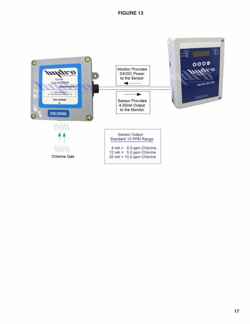
2. Sensor Monitor Communication: Each monitor can be connected to one up to four sensors. The sensors are 24VDC loop powered by the monitor and the sensors provide a 4-20mA signal to the monitor. See Figure 13.
3. Initial Power Up: Each time the GA-170 power is turned on the alarms will be inactive for five minutes. A countdown will be shown on the display. This allows for the sensor(s) to stabilize.
4. Gas Density: For measured gases that are heavier than air, the gas sensor should be mounted 12" to 24" (30 to 60 cm) from the floor (Example: Figure 1a–Chlorine & Sulfur Dioxide). For measured gases that are lighter than air, the gas sensor should be mounted 12" to 24" (30 to 60 cm) from the ceiling (Example: Figure 1b–Ammonia).
FIGURE 1a FIGURE 1b
FIGURE 2
5. Sensor Protection: The sensor should not be exposed directly to extreme temperatures and/or conditions. It is very important not to allow the sensor element to get wet from rain or any other source because water will cause premature failure of the sensors.
6. Sensor Start Up: The sensor calibration cap must be removed upon start up. Upon removing the sensor cap, be sure to store it for later use. See Figure 2. The cap is used to protect the sensor during shipment and storage and the two ports on it are to be used for calibration with test gas.

4
7. Calibration: The Model GA-170 Gas Detectors are factory calibrated and do not require any calibration at startup. With the use of the calibration cap, the span calibration can be carried out if required. Be sure to retain the sensor calibration cap for such calibrations.
8. Response Checks (Bump Testing): To verify responsiveness, the gas sensors can be bump tested (exposed to a small amount of the target gas) in order to test the reaction of the sensor. A plastic squeeze bottle is provided with each gas detector for this purpose. See Figure 3. It is suggested that bump testing can be done at quarterly intervals, however required frequency is determined by environment, conditions, number of and severity of leaks. Proper bump testing (exposing the sensor to a modest amount of the fumes) will not substantially degrade the sensor or shorten sensor life. Depending on the environment, sensors can reliably last more than 5 years.
WARNING: Do NOT allow the liquid solution to directly contact the sensor membrane.
9. LED Indicators: If the sensor reading remains below the low alarm set point, then neither LED will illuminate. If the reading rises above the low alarm set point, then the “DANGER” LED will illuminate. If the reading rises above the high alarm set point, then the “ALARM” LED will illuminate.
B. Alarms and Output Signals 1. Acknowledgement of Alarms: If an alarm condition occurs, the alarm (red) LED will
illuminate and the relay will be activated. To acknowledge an alarm press the key. Pressing the key one time will silence the horn. Pressing the key a second time will deactivate the relays.
NOTE: Even after acknowledging the alarm, both LEDs will remain illuminated until the alarm condition has been removed.
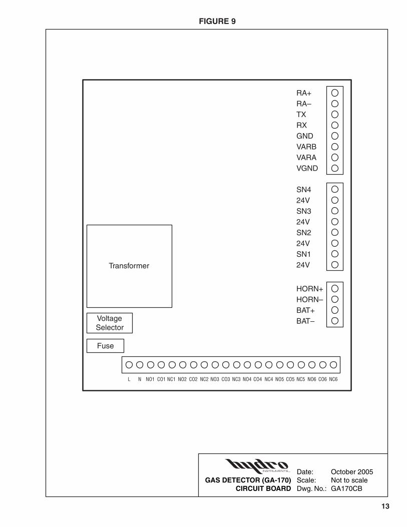
2. 4-20 mA output channels: A 4-20 mA output signal can be obtained from each sensor according to the wiring diagram (Figure 12). See Figures 9 through 13.
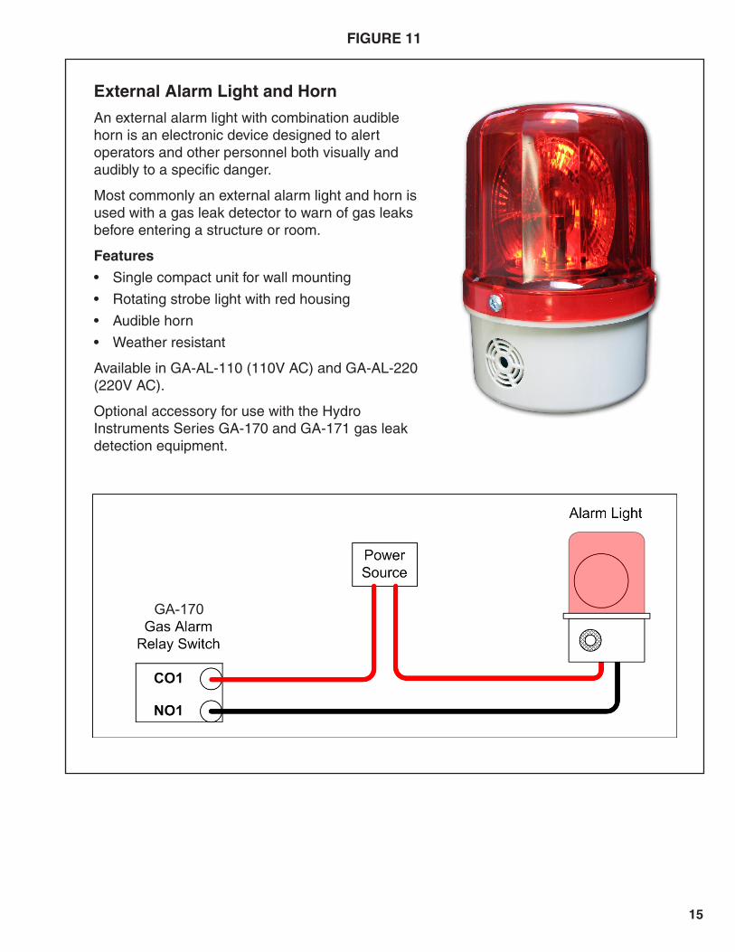
3. Alarm Relay: The GA-170 has six alarm relay outputs. The non-powered relays offer both normally open and normally closed connections. See Figures 9 and 10. See suggested relay wiring diagram (Figure 11).
FIGURE 3: Bump Testing (Chlorine Gas Example)
Bump Test Bottle
For Chlorine sensorsbottle contains 2 parts
NaClO solution (bleach)and 1 part vinegar

5
4. Alarm Explanation: Rising and Falling Alarms
a. Rising: If the Danger (Low Level Alarm) is set to a lower value than the Alarm (High Level Alarm), then the GA-170 will automatically configure the channel as a Rising Alarm (i.e., if the sensor reading is higher than the Danger or Alarm settings, then the GA-170 will activate alarm conditions).
b. Falling: If the Danger (Low Level Alarm) is set to a higher value than the Alarm (High Level Alarm), then the GA-170 will automatically configure the channel as a Falling Alarm (i.e., if the sensor reading is lower than the Danger or Alarm settings, then the GA-170 will activate alarm conditions).
c. Failsafe Alarms: If a sensor channel is set to Failsafe, then the corresponding High Level alarm relay will normally be energized. This will cause to reverse the NC/NO connections. Therefore, the NC connections will be OPEN unless an alarm condition is present or power is lost.
5. ALARM REFERENCE CHART (For one or two sensor units)
O – Inactive X – Active
Alarm Relay
Condition 1 2 3 4 5 6
Lost A/C Power O O O O X O
Lost Battery Power O O O O X O
Lost Sensor 4-20mA O O O O O X
Low Level Alarm Sensor #1 X O O O O O
High Level Alarm Sensor #1 O X O O O O
Low Level Alarm Sensor #2 O O X O O O
High Level Alarm Sensor #2 O O O X O O
6. ALARM REFERENCE CHART: (For three or four sensor units)
O – Inactive X – Active
Alarm Relay
Condition 1 2 3 4 5 6
Lost A/C Power O O O O X O
Lost Battery Power O O O O X O
Lost Sensor 4-20mA O O O O O X
High Level Alarm Sensor #1 X O O O O O
High Level Alarm Sensor #2 O X O O O O
High Level Alarm Sensor #3 O O X O O O
High Level Alarm Sensor #4 O O O X O O

6
FIGURE 4
7. RS-232 Output: Digital data output.
a. Use a standard “COM” cable with a DB9 connector and make the following connections:
DB9 Connector GA-170 Connections 2 TX 3 RX 5 GND
b. Run the Windows program “Hyperterminal” or any other terminal program. Set the COM communications as follows:
Flow Control: none Baud: 19,200 Format: 8 data bits, 1 start bit, 1 stop bit, no parity
C. Operation Screens This section explains the features of the standard operating screens of the GA-170.
NOTE: Navigate between the display screens below using the and keys. See Figure 4.
1. Home Screens (1 & 2): These screens display the gas type and reading of the sensor(s).
2. Test Operation (3): This screen allows manual testing of the horn and relays. Pressing will activate the horn. Pressing will activate all relays.
3. Status Screens (4 & 5): These screens display all present alarm conditions.
4. Password Screen (6): See Section II.A for instructions on this screen and the configuration section.
1 Cl2 0.0 PPM2 CO 0.0 PPM
Test Operation+ Horn – Relays
Enter Password0 OK
GA-170 Operation Mode Screens
3 NH3 0.0 PPM4 SO2 0.0 PPM
1 Status: Normal2 Status: Normal
3 Status: Normal4 Status: Normal
This icon indicates that A/C Poweris connected to the instrument.
This icon indicates that Battery Poweris connected to the instrument.
1
2
3
4
5
6
NOTE: The shaded screens in Figure 4 are not shown unless sensor 3 or sensor 4 is activated.

7
Status messages
1. Normal: Indicates that the sensor reading is above 2 mA and below the alarm set point.
2. Danger: Indicates that the sensor reading exceeds the low alarm setting, but is lower than the high alarm setting. (Meaning that if the low alarm setting is at 1.0 PPM and the high alarm setting is at 2.0 PPM, then the status will be “Danger” if the reading is between 1.0 PPM and 2.0 PPM.)
3. Alarm: Indicates that the sensor reading exceeds the high alarm setting. (Meaning that if the high alarm setting is at 2.0 PPM, then status will be “Alarm” if the reading is 2.0 PPM or higher.)
4. Error: Indicates that the sensor signal is below 2 mA and usually indicates that the sensor is either damaged or not connected.
D. Battery Backup
1. Disconnect the A/C Power before beginning this procedure.
2. The battery has Velcro strips attached. Remove the clear surface protection tape and place the battery into the bottom of the enclosure with the single strip against the rear of the box.
3. WARNING!!! Pay careful attention to which lead is – and which is + on the battery. The leads are marked on the battery. If you switch the leads to the circuit board you will damage the device. Connect the + of the battery to BAT+ and the – of the battery to BAT–.
4. Battery is now installed.
5. See configuration Section II.B of the manual to follow the procedure to activate the battery backup using the keypad and display.
6. The unit will keep the battery charged and ready for use. The battery will require approximately 12 hours to be fully charged.
NOTE: When the battery level falls below ~8.5 Volts it is automatically disconnected from the circuit board. After this has occurred, the unit can only be powered up by restoring A/C power.

8
II. CONFIGURATION OF PARAMETERS
Configuration of Sensor Parameters & Calibration of Sensors Each GA-170 Gas Detector will be set up from the factory as per the ordering instructions. However, settings and sensors can be changed using the following procedure.
A. Entering Setup: All parameters are set in the password protected setup section.
1. Press the key until the password screen is reached.
2. Use the and keys to set the password. The password is “170”.
3. Press the key so that “OK” is flashing and then press the key.
B. Configuring Each Channel See Figure 5. The first screen allows selection of the display units (PPM or %) and whether or not
to enable the battery back-up. Press the down arrow to come to the second screen where selection is made among which channel to configure. Move between the channels with the and keys. When the desired channel is flashing, press the key to enter setup for that channel. Setup for each channel is identical.
1. GAS TYPE: This parameter adjusts the gas type to be displayed for this sensor. You can navigate through the list of gases using the and keys. Adjustment of this parameter is only required if the sensor type is being changed. NOTE: The gas type must match what the sensor was designed to detect.
PRESS TO GO TO THE NEXT PARAMETER
2. DECIMAL POSITION: Select the decimal position for display of the measured value.
PRESS TO GO TO THE NEXT PARAMETER
3. FULL SCALE: This parameter must be set to match the full scale of the sensor being used. (Example: If the sensor has a 0.0-10.0 PPM range, then this parameter must be set to 10.0 PPM. If this setting does not match the sensor range, then the GA-170 will not display the correct sensor reading.) Adjustment of this parameter is only required if the sensor type is being changed.
PRESS TO GO TO THE NEXT PARAMETER
4. ZERO CALIBRATION: After the sensor is installed with the calibration cap removed the display should read 0.0 ppm if no target gas is present. If the reading is not 0.0 PPM on this screen, then use the key to increase the reading or the key to reduce the reading. Press and release the keys each time. Do not press and hold the keys. After adjusting, wait 10 seconds to confirm that the reading is stable before proceeding to the next step.
PRESS TO GO TO THE NEXT PARAMETER
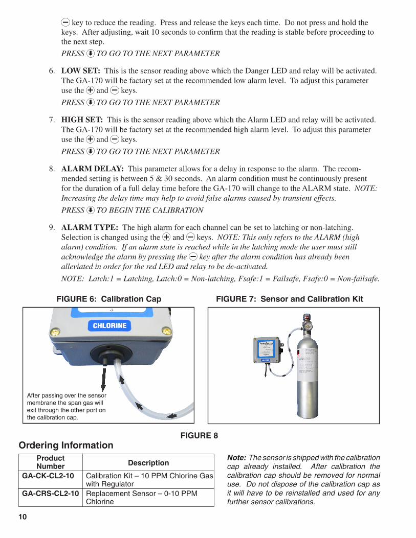
5. SPAN CALIBRATION: The gas detector system is factory calibrated and does not require calibration upon installation setup. Span calibration is rarely required, however, it may be required or desired to perform span calibrations periodically over the life of the sensor. If calibration is to be carried out, then the appropriate span gas calibration kit must be purchased. See Figures 6, 7, and 8. The calibration cap must be installed on the sensor and connected as indicated in figures 6 and 7. Span gas must be allowed to flow at 500 cc/min for at least 1 or 2 minutes until the displayed reading stabilizes. The reading on this screen should be adjusted to match the ppm value of the span gas being used. Use the key to increase the reading or the

9
FIGURE 5
Setup ChannelsCh1 Ch2 Ch3 Ch4
Display: PPMBattery: No
Sensor 1 setup screens
Ch1Gas Type:
Cl2
Ch1 Decimal Posn:
XXX.X
Ch1 Full Scale:
10.0 PPM
Ch1 Zero Calibration:
0.0 PPM 0%
Ch1 Span Calibration:
5.0 PPM 50%
Ch1 Low Set:
1.0 PPM 10%
Ch1 High Set:
2.0 PPM 20%
Ch1 Alarm Delay:
10 secs
Ch1 Alarm Type:
Latch: 1 Fsafe: 0
GA-170 Setup Mode Screens
1
2
3
4
5
6
7
8
9
10
After passing over the sensor membrane the span gas will exit through the other port on the calibration cap.
key to reduce the reading. Press and release the keys each time. Do not press and hold the keys. After adjusting, wait 10 seconds to confirm that the reading is stable before proceeding to the next step.
PRESS TO GO TO THE NEXT PARAMETER
6. LOW SET: This is the sensor reading above which the Danger LED and relay will be activated. The GA-170 will be factory set at the recommended low alarm level. To adjust this parameter use the and keys.
PRESS TO GO TO THE NEXT PARAMETER
7. HIGH SET: This is the sensor reading above which the Alarm LED and relay will be activated. The GA-170 will be factory set at the recommended high alarm level. To adjust this parameter use the and keys.
PRESS TO GO TO THE NEXT PARAMETER
8. ALARM DELAY: This parameter allows for a delay in response to the alarm. The recom-mended setting is between 5 & 30 seconds. An alarm condition must be continuously present for the duration of a full delay time before the GA-170 will change to the ALARM state. NOTE: Increasing the delay time may help to avoid false alarms caused by transient effects.
PRESS TO BEGIN THE CALIBRATION
9. ALARM TYPE: The high alarm for each channel can be set to latching or non-latching. Selection is changed using the and keys. NOTE: This only refers to the ALARM (high alarm) condition. If an alarm state is reached while in the latching mode the user must still acknowledge the alarm by pressing the key after the alarm condition has already been alleviated in order for the red LED and relay to be de-activated.
NOTE: Latch:1 = Latching, Latch:0 = Non-latching, Fsafe:1 = Failsafe, Fsafe:0 = Non-failsafe.
FIGURE 6: Calibration Cap
FIGURE 8
FIGURE 7: Sensor and Calibration Kit
Note: The sensor is shipped with the calibration cap already installed. After calibration the calibration cap should be removed for normal use. Do not dispose of the calibration cap as it will have to be reinstalled and used for any further sensor calibrations.
Ordering Information Product Number Description
GA-CK-CL2-10 Calibration Kit – 10 PPM Chlorine Gas with Regulator
GA-CRS-CL2-10 Replacement Sensor – 0-10 PPM Chlorine
11
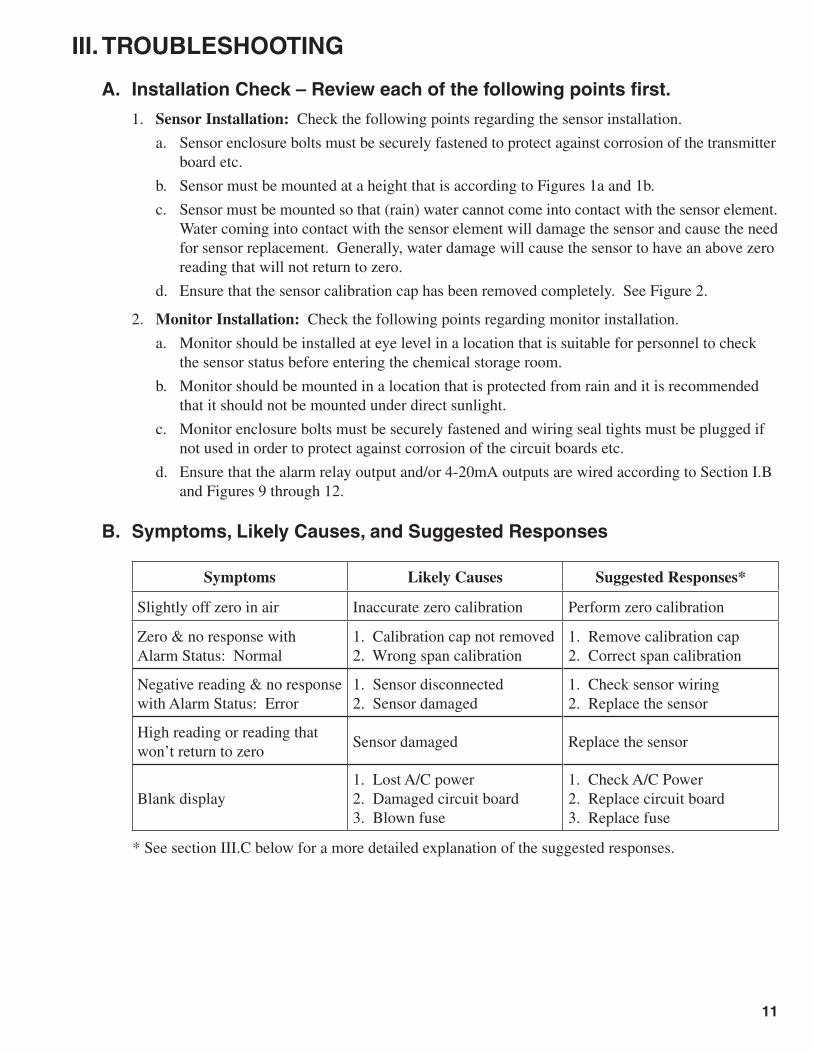
III. TROUBLEShOOTING
A. Installation Check – Review each of the following points first.
1. Sensor Installation: Check the following points regarding the sensor installation.
a. Sensor enclosure bolts must be securely fastened to protect against corrosion of the transmitter board etc.
b. Sensor must be mounted at a height that is according to Figures 1a and 1b.
c. Sensor must be mounted so that (rain) water cannot come into contact with the sensor element. Water coming into contact with the sensor element will damage the sensor and cause the need for sensor replacement. Generally, water damage will cause the sensor to have an above zero reading that will not return to zero.
d. Ensure that the sensor calibration cap has been removed completely. See Figure 2.
2. Monitor Installation: Check the following points regarding monitor installation.
a. Monitor should be installed at eye level in a location that is suitable for personnel to check the sensor status before entering the chemical storage room.
b. Monitor should be mounted in a location that is protected from rain and it is recommended that it should not be mounted under direct sunlight.
c. Monitor enclosure bolts must be securely fastened and wiring seal tights must be plugged if not used in order to protect against corrosion of the circuit boards etc.
d. Ensure that the alarm relay output and/or 4-20mA outputs are wired according to Section I.B and Figures 9 through 12.
B. Symptoms, Likely Causes, and Suggested Responses
Symptoms Likely Causes Suggested Responses*
Slightly off zero in air Inaccurate zero calibration Perform zero calibration
Zero & no response withAlarm Status: Normal
1. Calibration cap not removed2. Wrong span calibration
1. Remove calibration cap2. Correct span calibration
Negative reading & no response with Alarm Status: Error
1. Sensor disconnected2. Sensor damaged
1. Check sensor wiring2. Replace the sensor
High reading or reading thatwon’t return to zero
Sensor damaged Replace the sensor
Blank display1. Lost A/C power2. Damaged circuit board3. Blown fuse
1. Check A/C Power2. Replace circuit board3. Replace fuse
* See section III.C below for a more detailed explanation of the suggested responses.

12
C. Explanation of Responses
1. Zero Calibration: If the display is not reading 0.0 PPM in air, then adjust the zero calibration. Refer to Section II.B.4 and Figure 5.
2. Calibration Cap: The calibration cap is installed for protection of the sensor during shipping and storage, but must be removed upon installation. If the sensor cap is not removed, then there will be no response or a very slow response. Refer to Section I.A.6 and Figure 2.
3. Span Calibration: If the span calibration is performed incorrectly (usually accidentally done in air with zero target gas) then this will cause the readings to be inaccurate. Unless you intend to perform the span calibration and have a span gas calibration kit, do not touch the and keys if you enter the span calibration screen. See Section II.B.5 and Figures 6, 7, and 8.
4. Sensor Wiring: If the display is reading a negative value and giving an “Alarm Status: Error” message, then the sensor may not be connected to the monitor. Check the wiring at the circuit board in the monitor and inside the sensor enclosure. See Figures 9 and 10.
5. Sensor Replacement: Repeated or excessive exposure to the target gas will eventually cause failure of the sensor. If water is allowed to contact the sensor element this will also eventually cause failure of the sensor. Under normal circumstances a sensor life is typically 2 years or more. However, lightning, other power surges, chemical leaks, and contact with water can all cause sensor failure. Replacement sensors are easily installed with the quick disconnect fitting.
6. Damaged Circuit Board: The circuit boards can be damaged if high voltage is connected to the wrong terminals, by lightning, other power surges, or by corrosion. If you believe that the circuit board is damaged, then contact the factory and your local sales representative. Refer to Figures 9 and 10.
7. Blown Fuse: If the circuit board has no power, then always check to see if the fuse is blown and replace if necessary.
13
FIGURE 9
Date: October 2005 GAS DETECTOR (GA-170) Scale: Not to scale CIRCUIT BOARD Dwg. No.: GA170CB
RA+RA–TXRXGNDVARBVARAVGND
SN424VSN324VSN224VSN124V
HORN+HORN–BAT+BAT–
L N NO1 CO1 NC1 NO2 CO2 NC2 NO3 CO3 NC3 NO4 CO4 NC4 NO5 CO5 NC5 NO6 CO6 NC6
Transformer
VoltageSelector
Fuse

14
FIGURE 10
G
A-1
70 G
AS
DE
TE
CT
OR
D
ate:
N
ovem
ber
2010
W
IRIN
G C
ON
NE
CT
ION
S
Dw
g. N
o.
GA
-170
-WC
BA
TT
ER
Y
INS
IDE
CO
VE
RIN
SID
E B
OX
RA
+R
A–
TX
RX
GN
DV
AR
BV
AR
AV
GN
D
NC6CO6NO6NC5CO5NO5NC4CO4NO4NC3CO3NO3NC2CO2NO2NC1CO1NO1NL
SN
424
VS
N3
24V
SN
224
VS
N1
24V
HR
N+
HR
N–
BAT
+B
AT–
LINE 1
NEUT
GN
D
Tran
sfor
mer
Vol
tage
Sel
ecto
r
Fus
e
Neg
ativ
eB
atte
ryTe
rmin
al
90 d
B H
orn
To S
enso
r 1
A/C
Pow
erTo
Sen
sor
2
Pos
itive
Bat
tery
Term
inal
15
GA-170
External Alarm Light and Horn
An external alarm light with combination audible horn is an electronic device designed to alert operators and other personnel both visually and audibly to a specific danger.
Most commonly an external alarm light and horn is used with a gas leak detector to warn of gas leaks before entering a structure or room.
Features
• Single compact unit for wall mounting
• Rotating strobe light with red housing
• Audible horn
• Weather resistant
Available in GA-AL-110 (110V AC) and GA-AL-220 (220V AC).
Optional accessory for use with the Hydro Instruments Series GA-170 and GA-171 gas leak detection equipment.
FIGURE 11

16
FIGURE 12
GA-170 Gas Alarm 4-20 mA Output:1. Remove the red sensor wire from the 24V circuit board terminal.
2. Splice the red sensor wire to the black wire in the signal cable.
3. Connect the red wire in the signal cable to the same 24V circuit board terminal that was being used.
NOTE: If the 4-20 mA output is not connected to a device the circuit will not be complete and the sensor will not function. You may short the wires together to complete the circuit if not utilizing the 4-20 mA output.
Red Sensor Wire Splice
4-20 mAOutput
Black Sensor Wire
To S
N1
onC
ircui
t Boa
rd
To 2
4V o
nC
ircui
t Boa
rd
Top
Bot
tom
Black Signal Wire
Red Signal Wire
17
FIGURE 13