
G7 Relay I/O Blocks and Cables 383 - Omron …wiringsystem...Wiring Systems 383 Programmable...
44
383 Wiring Systems Programmable Controllers Wiring Systems G7@ Relay I/O Blocks and Cables 383 G70A I/O Terminal Bases 386 G70D Relay Output Terminal Blocks 387 G70R Relay Output Terminal Block 395 G7TC Relay I/O Terminal Blocks 398 G79 Cables 401 XW2@ I/O Terminal Blocks and Cables 403 XW2B I/O Terminal Blocks 405 XW2C I/O Terminal Blocks 408 XW2D I/O Terminal Blocks 409 XW2Z Cables 412 I/O Connecting Cable Selection Guide 416
Transcript of G7 Relay I/O Blocks and Cables 383 - Omron …wiringsystem...Wiring Systems 383 Programmable...

383Wiring Systems
Pro
gra
mm
able
C
on
tro
llersWiring Systems
G7@ Relay I/O Blocks and Cables 383G70A I/O Terminal Bases 386G70D Relay Output Terminal Blocks 387G70R Relay Output Terminal Block 395G7TC Relay I/O Terminal Blocks 398G79 Cables 401
XW2@ I/O Terminal Blocks and Cables 403XW2B I/O Terminal Blocks 405XW2C I/O Terminal Blocks 408XW2D I/O Terminal Blocks 409XW2Z Cables 412
I/O Connecting Cable Selection Guide 416
Y201-EN2-03.book Seite 383 Donnerstag, 30. März 2006 1:52 13

384 Programmable Controllers
Wiring SystemsIntroduction to I/O Blocks, I/O Terminals, and I/O Block Bases
G70D, G7TC, and G70A-ZOC16Unify Wiring with One Connecting Cable.Simplify Connections to the Controller and Reduce Wiring in the Control Panel.Improve Surge Suppression and Increase Capacity at the Same Time.
Compact Output Terminals Save Control Panel Space• The G70D Series consists of 16-point Relay Output Terminals.• Two configurations are available: The standard low-profile version is just 156 × 51 × 39 mm (W× D× H) and the vertical version
is just 135 × 46 × 81 mm (W× D× H).• Relay output models are equipped with G6D power relays (low-profile: SPST-NO 3 A/common; vertical: SPST-NO 3 A/output)
and power MOSFET relay models are equipped with G3DZ power MOSFET relays (SPST-NO 0.3 A/output).• The flat models have 2 common terminals. The vertical models have 16 independent outputs.Note: See page 392 and page 387 for more details.
Both Input Blocks and Output Blocks are Available. G7TC I/O Blocks are Ideal as Controller Interfaces.• Output Blocks with 8 or 16 outputs are available. Input Blocks
with 16 inputs are available.• The 16-point Output Blocks are available with PNP circuits.• The 16-point models are just 182 × 85 × 68 mm (W× D× H)
and the 8-point models are just 102 × 85 × 68 mm (W× D× H).
• Equipped with G7T I/O Relays (SPST-NO 5 A/output).• G7TC models conform to UL and CSA standards.• 16-point models with independent terminals.• Models are also available with G3TA Solid State Relays.Note: See page 398 for more details.
High-capacity Relay Sockets can be Equipped with G2R (SPDT) Relays.• Sixteen relay terminal sockets for output relays only.• Models are available with PNP circuits.• Compact case is just 234 × 75 × 64 mm (W× D× H).• Install OMRON G2R Power Relays, G3R Solid State Relays,
G3RZ Power MOSFET Relays, and H3RN Timers as required. (Relays and Timers are sold separately.)
• High-capacity 10-A Terminal Block• Conforms to VDE standards.• Sixteen independent terminalsNote: See page 386 for more details.
G70D
G7TC
Vertical models (G70D-VSOC16/VFOM16)
Low-profile models (G70D-SOC16/FOM16)
16-point model 8-point model
G70A-ZOC16
*Relays are sold separately.
Y201-EN2-03.book Seite 384 Donnerstag, 30. März 2006 1:52 13

G70D, G7TC, and G70A-ZOC16 385
Pro
gra
mm
able
C
on
tro
llers
Space-saving and Labor-saving 8-point Output Block• Compact terminal block is just 68 × 80 × 44 mm (W × H × D,
when mounted upright).• Independent contacts and shorting bars allow easy common
connections. • The common can now be connected with a shorting bar in the
G70D-SOC08 and G70R-SOC08.• No tools are required to remove Relays, so Relay replace-
ment is easier than ever.• The attached terminal cover prevents shocks.• Equipped with operation indicators.• Built-in diodes absorb coil surge.• Mount either to DIN rail or via screws.Note: See page 389 for details.
Space-saving and Labor-saving 8-point Output Block• Compact terminal block is just 136 × 80 × 55 mm (W × H ×
D, when mounted upright).• Independent contacts and shorting bars allow easy common
connections.• The common can now be connected with a shorting bar in the
G70D-SOC08 and G70R-SOC08.• No tools are required to remove Relays, so Relay replace-
ment is easier than ever.• The attached terminal cover prevents shocks.• Built-in diodes absorb coil surge.• Mount either to DIN rail or via screws.Note: See page 395 for details.
G70D-SOC08
G70R-SOC08
Y201-EN2-03.book Seite 385 Donnerstag, 30. März 2006 1:52 13
386 Programmable Controllers
G70A-ZOC16
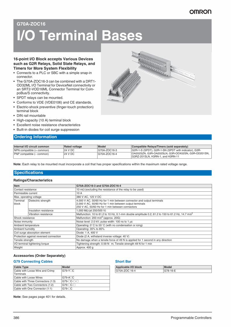
I/O Terminal Bases16-point I/O Block accepts Various Devices such as G2R Relays, Solid State Relays, and Timers for More System Flexibility• Connects to a PLC or SBC with a simple snap-in
connector.• The G70A-ZOC16-3 can be combined with a DRT1-
OD32ML I/O Terminal for DeviceNet connectivity or an SRT2-VOD16ML Connector Terminal for Com-poBus/S connectivity.
• SPDT relays can be mounted.• Conforms to VDE (VDE0106) and CE standards.• Electric-shock preventive (finger-touch protection)
terminal block• DIN rail mountable• High-capacity (10 A) terminal block• Excellent noise resistance characteristics• Built-in diodes for coil surge suppression
Note: Each relay to be mounted must incorporate a coil that has proper specifications within the maximum rated voltage range.
Ratings/Characteristics
Accessories (Order Separately)
G79 Connecting Cables
Note: See pages page 401 for details.
Short Bar
Ordering Information
Internal I/O circuit common Rated voltage Model Compatible Relays/Timers (sold separately)NPN compatible (+ common) 24 V DC G70A-ZOC16-3 G2R-1-S (SPDT), G2R-1-SN (SPDT with indicator), G3R-
OA202SZN, G3R-OA202SLN, G3R-ODX02SN, G3R-OD201SN, G3RZ-201SLN, H3RN-1, and H3RN-11
PNP compatible (– common) 24 V DC G70A-ZOC16-4
Specifications
Item G70A-ZOC16-3 and G70A-ZOC16-4Contact resistance 10 mΩ (excluding the resistance of the relay to be used)Permissible current 10 AMax. operating voltage 380 V AC, 125 V DCTerminal block
Dielectric strength 4,000 V AC, 50/60 Hz for 1 min between connector and output terminals2,000 V AC, 50/60 Hz for 1 min between output terminals250 V AC, 50/60 Hz for 1 min between connectors
Insulation resistance 1,000 MΩ (at 250/500 V)Vibration resistance Malfunction: 10 to 61.2 to 10 Hz, 0.1-mm double amplitude 0.2; 61.2 to 150 to 61.2 Hz, 14.7 m/s2
Shock resistance Malfunction: 200 m/s2 (approx. 20G)Noise immunity Noise level: 2.0 kV; pulse width: 100 ns to 1 μsAmbient temperature Operating: 0° C to 55° C (with no condensation or icing)Ambient humidity Operating: 35% to 85%Coil surge absorption element Diode: 1 A, 400 VProtection against reversed connection Diode (2 A, withstand inverse voltage: 40 V)Tensile strength No damage when a tensile force of 49 N is applied for 1 second in any directionI/O terminal tightening torque Tightening strength: 0.59 N⋅ m; Tensile strength 49 N for 1 minWeight Approx. 400 g
Cable Type ModelCable with Loose Wire and Crimp Terminals
G79-Y@C
Cable with Loose Wires G79-A@CCable with Three Connectors (1:3) G79-@C-@-@Cable with Two Connectors (1:2) G79-@C-@Cable with One Connector (1:1) G79-@C
Applicable I/O block ModelG70A-ZOC 16-4 G78-16-E
Y201-EN2-03.book Seite 386 Donnerstag, 30. März 2006 1:52 13

387Relay output terminal blocks
Pro
gra
mm
able
C
on
tro
llers
G70D
Relay output terminal blocksCompact, Low-profile 16-point Output Block• Compact terminal block is just 156 × 51 × 39 mm
(W × D × H)• Models with Power MOSFET Relays are available
for high-frequency switching of AC or DC loads.• Wire loads directly from terminal blocks; no need for
relaying.• Operation indicators show each I/O signal’s
ON/OFF status at a glance.• The G70D-SOC16 and G70D-FOM16 can be
combined with a DRT1-OD32ML I/O Terminal for DeviceNet connectivity or an SRT2-VOD16ML Connector Terminal for CompoBus/S connectivity.
• Equipped with surge-absorbing diodes.• Relay Removal Tool included.• Mount either to DIN rail or via screws.
These are all non-standard model and require a special order. Contact your OMRON representative for details on availability.
Ratings
Relay SpecificationsNote: The following specifications apply to G6D Relays mounted in a
G70D Output Block and not the G6D Relay itself.
Coil Ratings (per G6D Relay)
Note: 1. The must-operate voltage is 75% or less of the rated voltageif the relay is mounted upside down.
2. Rated current and coil resistance were measured at a coiltemperature of 23° C with a tolerance of ±10%.
3. Operating characteristics were measured at a coil tempera-ture of 23° C.
4. The maximum allowable voltage is the maximum value of theallowable voltage range for the relay coil operating power sup-ply. There is no continuous allowance.
5. The rated current includes the terminal’s LED current.
Contact Ratings (per G6D Relay)
Note: 1. Up to 3 A can be carried by the power supply terminals foroutputs (terminals B0 to B7.)
2. This value is for a switching frequency of 120 times perminute.
Ordering Information
Classification Points Internal output circuit common Rated voltage ModelRelay outputs 16 points (SPST-NO × 16) NPN compatible (+common) 24 V DC G70D-SOC16
PNP compatible (– common) G70D-SOC16-1Power MOSFET relay outputs NPN compatible (+ common) G70D-FOM16
PNP compatible (– common) G70D-FOM16-1
Specifications
Rated voltage 24 V DCRated current 10.5 mACoil resistance 2,880 ΩMust-operate voltage 70% max. of rated voltageMust release voltage 10% min. of rated voltageMax. voltage 130% of rated voltagePower consumption Approx. 200 mW
Load Resistive load (cosφ = 1)Rated load 3 A at 250 V AC, 3 A at 30 V DCRated carry current 3 AMax. switching voltage 250 V AC, 30 V DCMax. switching current 3 AMin. permissible load (reference value)(see note 2)
10 mA at 5 V DC
Life expectancy Electrical: 100,000 operations min. (un-der and at the rated load at 1,800 oper-ations/hr)Mechanical: 20,000,000 operations min. (at 18,000 operations/hr)
Y201-EN2-03.book Seite 387 Donnerstag, 30. März 2006 1:52 13

388 Programmable Controllers
Power MOSFET Relay Specifications
Input (per G3DZ Power MOSFET Relay)
Note: The rated current includes the terminal’s LED current.
Output (per G3DZ Power MOSFET Relay)
Characteristics
Note: 1. These values are initial values.2. Measurement condition: 1 A at 5 V DC3. Ambient temperature: 23° C4. Current consumption is when all points are ON and includes G6D Relay coil current but does not include any external load current.5. Current consumption is when all points are ON and includes G3DZ input current but does not include any external load current.
Accessories (Order Separately)
G79 Connecting Cables
Note: See page 401 for details.
Replacement Relays
Note: This is a non-standard model and requires a special order. Contact your OMRON representative for details on availability.
Rated voltage 24 V DCOperating voltage 19.2 to 28.8 V DCVoltage level Must-operate 19.2 V DC max.
Must release 1 V DC min.Input impedance 4 kΩ±20%Rated current 8.2 mA±20%
Load voltage 3 to 264 V AC, 3 to 125 V DCLoad current 100 μA to 0.3 AInrush current 6 A (10 ms)
Item G70D-SOC16(-1) G70D-FOM16(-1)Classification Relay outputs Power MOSFET relay outputsContact form 16 points (SPST-NO × 16)Contact mechanism Single ---Contact material AgCdO ---Contact resistance 100 mΩ max. (see note 2) ---Isolation method --- PhotocouplerMust-operate time 10 ms max. (see note 3) 6 ms max.Release time 10 ms max. (see note 3)Output ON-resistance --- 2.4 Ω max.Open-state leakage current --- 10 μA max. (at 125 V DC)Max. switching frequency Mechanical:18,000 operations/hr
Rated load:1,800 operations/hr---
Insulation resistance 100 MΩ min. (at 500 V DC)Dielectric strength 2,000 V AC for 1 min between coil and contact 2,000 V AC for 1 min between input and output terminalsNoise immunity Power input (normal mode): 600 V for 10 min with a pulse width of 100 ns to 1 μs
Power input (common mode): 1.5 kV for 10 min with a pulse width of 100 ns to 1 μsInput cable (coiling): 1.5 kV for 10 min with a pulse width of 100 ns to 1 μsUnit body (coiling): 600 V for 10 min with a pulse width of 100 ns to 1 μs
Vibration resistance Destruction: 10 to 55 to 10 Hz, 0.5-mm amplitude (1.0-mm double)Malfunction: 10 to 55 to 10 Hz, 0.375-mm amplitude (0.75-mm double)
Shock resistance Destruction:300 m/s2 (approx. 30G), Malfunction:100 m/s2 (approx. 10G)Operating voltage range 24 V DC +10%/–15%Current consumption Approx. 300 mA at 24 V DC (see note 4) Approx. 300 mA at 24 V DC (see note 5)Cable length Between block and controller: 5 m max. (reference value for AWG28)
Between block and external device: Dependent on loadLED color Operation indicator: orange; power supply: greenCoil surge absorber Diode (400 V, 300 mA)Ambient temperature Operating: 0° C to 55° CAmbient humidity Operating: 35% to 85%Mounting strength No damage when 5 kgf (49 N) pull load was applied for 1 s in all directions
(except for 1 kgf (9.8 N) in direction of rail)Terminal strength Tightening torque: 0.78 to 0.98 N·m), Pull strength: 49 N for 1 minWeight Approx. 200 g
Cable Type ModelCable with Loose Wire and Crimp Ter-minals
G79-Y@C
Cable with Loose Wires G79-A@CCable with Three Connectors (1:3) G79-@C-@-@Cable with Two Connectors (1:2) G79-@C-@Cable with One Connector (1:1) G79-@C
Applicable Output Block
Rated voltage Model
G70D-SOC16G70D-SOC16-1
24 V DC G6D-1A
G70D-FOM16G70D-FOM16-1
24 V DC G3DZ-2R6PL (see note)
Y201-EN2-03.book Seite 388 Donnerstag, 30. März 2006 1:52 13

389Relay Output Terminal Block
Pro
gra
mm
able
C
on
tro
llers
G70D-SOC08
Relay Output Terminal BlockSpace-saving and Labor-saving 8-point Output Block• Compact terminal block is just 68 × 80 × 44 mm
(W × H × D, when mounted upright)..• Independent contacts and shorting bars allow easy
common connections.• The common can now be connected with a shorting
bar in the G70D-SOC08 and G70R-SOC08.• No tools are required to remove Relays, so Relay
replacement is easier than ever.• The attached terminal cover prevents shocks.• Equipped with operation indicators.• Built-in diodes absorb coil surge.• Mount either to DIN rail or via screws.
Ordering Information
This is a non-standard model and requires a special order. Contact your OMRON representative for details on availability.
RatingsThe following specifications apply to G6D Relays mounted in a G70D Output Block and not the G6D Relay itself.
Coil Ratings (per G6D Relay)
Note: 1. The must-operate voltage is 75% max. of the rated voltage ifthe Relay is mounted upside down.
2. Rated current and coil resistance were measured at a coiltemperature of 23° C with a tolerance of ±10%.
3. Operating characteristics were measured at a coil tempera-ture of 23° C.
4. The maximum allowable voltage is the maximum value of theallowable voltage range for the relay coil operating power sup-ply. There is no continuous allowance.
5. The rated current includes the current consumption of the op-eration indicator.
Contact Ratings (per G6D Relay)
Note: This value is for a switching frequency of 120 times per minute.
Classification Points Internal output circuit common Rated voltage ModelRelay outputs 8 points (SPST-NO × 8) NPN compatible (+ common) 24 V DC G70D-SOC08
Specifications
Rated voltage
Rated current
Coil resis-tance
Must-op-erate volt-age
Release voltage
Max. al-lowable voltage
Power con-sumption
24 V DC 10.5 mA 2,880 Ω 70% max. of rated voltage
10% min. of rated voltage
130% Approx. 200 mW
Item Load Resistive load (cosφ = 1)Rated load 5 A at 250 V AC, 5 A at 30 V DCRated carry current 5 AMax. switching voltage 250 V AC, 30 V DCMax. switching current 5 AMax. switching capacity (reference value)
1,250 VA, 150 W
Min. permissible load (reference value; see note.)
5 V DC, 10 mA
Life expectancy Electrical 100,000 operations min. (at or below the rated load at 1,800 operations/hr)
Mechanical 20,000,000 operations min. (at 18,000 operations/hr)
Y201-EN2-03.book Seite 389 Donnerstag, 30. März 2006 1:52 13
390 Programmable Controllers
Characteristics
Note: 1. These values are initial values.2. Measurement conditions: 1 A at 5 V DC3. Ambient temperature: 23° C4. The current consumption is the value when all points are ON and includes the G6D Relay coil current.
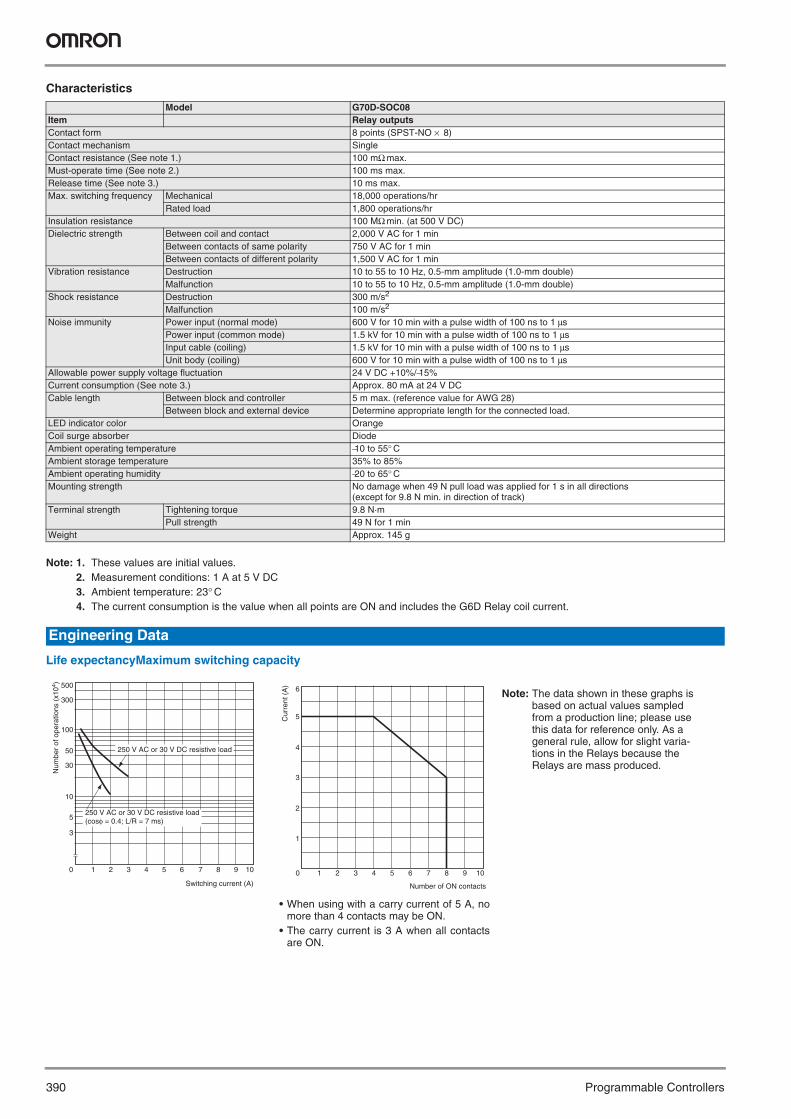
Life expectancyMaximum switching capacity
Model G70D-SOC08Item Relay outputsContact form 8 points (SPST-NO × 8)Contact mechanism SingleContact resistance (See note 1.) 100 mΩ max.Must-operate time (See note 2.) 100 ms max.Release time (See note 3.) 10 ms max.Max. switching frequency Mechanical 18,000 operations/hr
Rated load 1,800 operations/hrInsulation resistance 100 MΩ min. (at 500 V DC)Dielectric strength Between coil and contact 2,000 V AC for 1 min
Between contacts of same polarity 750 V AC for 1 minBetween contacts of different polarity 1,500 V AC for 1 min
Vibration resistance Destruction 10 to 55 to 10 Hz, 0.5-mm amplitude (1.0-mm double)Malfunction 10 to 55 to 10 Hz, 0.5-mm amplitude (1.0-mm double)
Shock resistance Destruction 300 m/s2
Malfunction 100 m/s2
Noise immunity Power input (normal mode) 600 V for 10 min with a pulse width of 100 ns to 1 μsPower input (common mode) 1.5 kV for 10 min with a pulse width of 100 ns to 1 μsInput cable (coiling) 1.5 kV for 10 min with a pulse width of 100 ns to 1 μsUnit body (coiling) 600 V for 10 min with a pulse width of 100 ns to 1 μs
Allowable power supply voltage fluctuation 24 V DC +10%/−15%Current consumption (See note 3.) Approx. 80 mA at 24 V DCCable length Between block and controller 5 m max. (reference value for AWG 28)
Between block and external device Determine appropriate length for the connected load.LED indicator color OrangeCoil surge absorber DiodeAmbient operating temperature −10 to 55° CAmbient storage temperature 35% to 85%Ambient operating humidity −20 to 65° CMounting strength No damage when 49 N pull load was applied for 1 s in all directions
(except for 9.8 N min. in direction of track)Terminal strength Tightening torque 9.8 N·m
Pull strength 49 N for 1 minWeight Approx. 145 g
Engineering Data
500
300
100
50
30
10
5
3
0 1 2 3 4 5 6 7 8 9 10
250 V AC or 30 V DC resistive load(cosφ = 0.4; L/R = 7 ms)
250 V AC or 30 V DC resistive load
Switching current (A)
Num
ber
of o
pera
tions
(x1
04 )
0 1 2 3 4 5 6 7 8 9 10
1
2
3
4
5
6
Number of ON contacts
Cur
rent
(A
)
• When using with a carry current of 5 A, nomore than 4 contacts may be ON.
• The carry current is 3 A when all contactsare ON.
Note: The data shown in these graphs is based on actual values sampled from a production line; please use this data for reference only. As a general rule, allow for slight varia-tions in the Relays because the Relays are mass produced.
Y201-EN2-03.book Seite 390 Donnerstag, 30. März 2006 1:52 13

Relay Output Terminal Block 391
Pro
gra
mm
able
C
on
tro
llers
Accessories for the G70D-SOC08 (Order Separately)
Shorting Bar
Replacement Relays
Note: The minimum permissible load (reference value) for the G6D-1A is 10 mA at 5 V DC.
Applicable Output Block ModelG70D-SOC08 G6B-4-SB
Applicable Output Block
Rated voltage Model
G70D-SOC08 24 V DC G6D-1A (See note.)G6D-1A-AP (See note.)
11.5 9.56.8
(32.3)
8.5 8.5 8.5
3.66.8
Y201-EN2-03.book Seite 391 Donnerstag, 30. März 2006 1:52 13

392 Programmable Controllers
G70D-VSOC16/-VFOM16
Relay output terminal blocksEasy-to-use, Space-saving 16-point Output Block• Slim terminal block is just 135 × 40 mm (W × D).• Independent contacts and short bars allow easy
common connections.• An Expansion Terminal Block can be mounted for
power line connections.• M3.5 fork-type crimp terminals (with a maximum ter-
minal width of 6.2 mm) can be used.• Lever mechanism allows Relays to be installed and
removed easily without tools.• Relay models and power MOSFET Relay models
are available.• Equipped with operation indicators.• Can be combined with a DRT1-OD32ML I/O Termi-
nal for DeviceNet connectivity or an SRT2-VOD16ML Connector Terminal for CompoBus/S connectivity.
• Built-in diode absorbs coil surge.• Mount either to DIN rail or via screws.
These are all non-standard model and require a special order. Contact your OMRON representative for details on availability.
Ratings
Relay SpecificationsNote: The following specifications apply to G6D Relays mounted in a G70D Output Block and not the G6D Relay itself.
Coil Ratings (per G6D Relay)
Note: 1. The must-operate voltage is 75% max. of the rated voltage ifthe Relay is mounted upside down.
2. Rated current and coil resistance were measured at a coiltemperature of 23° C with a tolerance of ±10%.
3. Operating characteristics were measured at a coil tempera-ture of 23° C.
4. The maximum allowable voltage is the maximum value of theallowable voltage range for the relay coil operating power sup-ply. There is no continuous allowance.
5. The rated current includes the current consumption of the op-eration indicator.
Contact Ratings (per G6D Relay)
Note: 1. Up to 5 A can be carried when 8 or fewer outputs are ON.2. This value is for a switching frequency of 120 times per
minute.
Ordering Information
Classification Points Internal output circuit common
Rated voltage Model
Relay outputs 16 points (SPST-NO × 16) NPN compatible(+ common)
24 V DC G70D-VSOC16Power MOSFET Relay outputs G70D-VFOM16
Specifications
Rated voltage 24 V DCRated current 10.5 mACoil resistance 2,880 ΩMust-operate voltage 70% max. of rated voltageRelease voltage 10% min. of rated voltageMax. allowable voltage 130% of rated voltagePower consumption Approx. 200 mW
Load Resistive load (cosφ = 1)Rated load 3 A at 250 V AC, 3 A at 30 V DCRated carry current 5 A (see note 1)Max. switching voltage 250 V AC, 30 V DCMax. switching current 5 AMax. switching capacity 1,250 VA, 150 WMin. permissible load (reference value) (See note .2)
5 V DC, 1 mA
Life expectancy Electrical: 100,000 operations min. (un-der and at the rated load at 1,800 oper-ations/hr), Mechanical: 20,000,000 operations min. (at 18,000 operations/hr)
Y201-EN2-03.book Seite 392 Donnerstag, 30. März 2006 1:52 13
Relay output terminal blocks 393
Pro
gra
mm
able
C
on
tro
llers
Power MOSFET Relay SpecificationsNote: The following values apply to G3DZ Relays mounted in a G70D Output Block and not the G3DZ Relay itself.
Input (per G3DZ Power MOSFET Relay)
Note: The rated current includes the current consumption of the oper-ation indicator.
Output (per G3DZ Power MOSFET Relay)
Characteristics
Note: 1. These values are initial values.2. Measurement condition: 1 A at 5 V DC3. Ambient temperature: 23° C4. Current consumption is when all points are ON and includes G6D Relay coil current but does not include any external load current.5. Current consumption is when all points are ON and includes G3DZ input current but does not include any external load current.6. The Unit weighs approximately 315 g with the Expansion Terminal Block mounted.
Rated voltage 24 V DCOperating voltage 19.2 to 28.8 V DCVoltage level Must operate 19.2 V DC max.
Must release 1 V DC min.Input impedance 4 kΩ±20%Rated current 8.2 mA±20%
Load voltage 3 to 264 V AC, 3 to 125 V DCLoad current 100 μA to 0.3 AInrush current 6 A (10 ms)
Item G70D-VSOC16 G70D-VFOM16Relay outputs Power MOSFET Relay outputs
Contact form 16 points (SPST-NO × 16)Contact mechanism Single ---Contact resistance 100 mΩ max. (see note 2) ---Isolation method --- PhotocouplerMust-operate time 10 ms max. (see note 3) 6 ms max.Release time 10 ms max. (see note 3) 10 ms max.Output ON-resistance --- 2.4 Ω max.Open-circuit leakage current --- 10 μA max. (at 125 V DC)Max. switching frequency Mechanical:18,000 operations/hr
Rated load:1,800 operations/hr---
Insulation resistance 100 MΩ min. (at 500 V DC)Dielectric strength 2,000 V AC for 1 min between coil and contact 2,000 V AC for 1 min between input and output terminalsNoise immunity Power input (normal mode): 600 V for 10 min with a pulse width of 100 ns to 1 μs
Power input (common mode): 1.5 kV for 10 min with a pulse width of 100 ns to 1 μsInput cable (coiling): 1.5 kV for 10 min with a pulse width of 100 ns to 1 μsUnit body (coiling): 600 V for 10 min with a pulse width of 100 ns to 1 μs
Vibration resistance Destruction: 10 to 55 to 10 Hz, 0.5-mm amplitude (1.0-mm double)Malfunction: 10 to 55 to 10 Hz, 0.375-mm amplitude (0.75-mm double)
Shock resistance Destruction: 300 m/s2, Malfunction: 100 m/s2
Operating voltage range 24 V DC +10%/–15%Current consumption Approx. 170 mA at 24 V DC (see note 4) Approx. 125 mA at 24 V DC (see note 5)Cable length Between block and controller:5 m max. (reference value for AWG28)
Between block and external device:Dependent on loadLED color Operation indicator: orangeCoil surge absorber Diode (600 V, 1 A)Ambient temperature Operating: –25° C to 55° C (with no icing or condensation)Ambient humidity Operating: 45% to 85%Mounting strength No damage when 49 N pull load was applied for 1 s in all directions (except for 9.8 N min. in direction of rail)Terminal strength Tightening torque: 0.78 to 1.18 N·m,
Pull strength: 49 N for 1 minTightening torque: 0.78 to 0.98 N·m, Pull strength: 49 N for 1 min
Weight (see note 6) Approx. 280 g
Y201-EN2-03.book Seite 393 Donnerstag, 30. März 2006 1:52 13

394 Programmable Controllers
Accessories (Sold Separately)
G79 Connecting Cables
Note: See page 401 for details.
Expansion Terminal Block
Note: This is a non-standard model and requires a special order. Contact your OMRON representative for details on availability.
Short Bar
Replacement Relays
Note: 1. The minimum permissible load (reference value) for the G6D-1A is 10 mA at 5 V DC.
2. The minimum permissible load (reference value) for the G6D-1A-AP is 1 mA at 5 V DC.
3. These are non-standard models and require a special order. Contact your OMRON representative for details on availability.
Cable Type ModelCable with Loose Wire and Crimp Terminals
G79-Y@C
Cable with Loose Wires G79-A@CCable with Three Connectors (1:3) G79-@C-@-@Cable with Two Connectors (1:2) G79-@C-@Cable with One Connector (1:1) G79-@C
Applicable Output Block Appearance ModelG70D-VSOC16 G70D-ET (see note)G70D-VFOM16
Applicable Output Block Appearance ModelG70D-VSOC16 G6D-4-SBG70D-VFOM16
Applicable Out-put Block
Rated voltage Model
G70D-VSOC16 24 V DC G6D-1A (see note 1)24 V DC G6D-1A-AP (see notes 2 and 3)
G70D-VFOM16 24 V DC G3DZ-2R6PL (see note 3)
Y201-EN2-03.book Seite 394 Donnerstag, 30. März 2006 1:52 13
395Relay output terminal block
Pro
gra
mm
able
C
on
tro
llers
G70R-SOC08
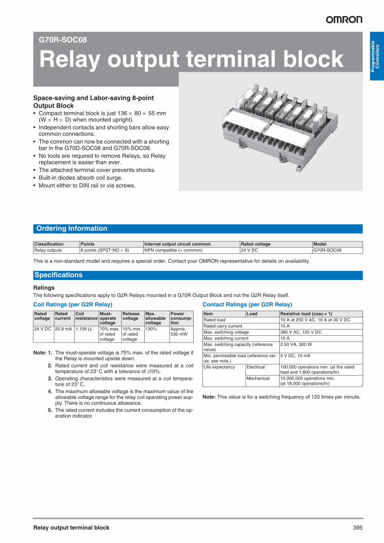
Relay output terminal blockSpace-saving and Labor-saving 8-point Output Block• Compact terminal block is just 136 × 80 × 55 mm
(W × H × D) when mounted upright).• Independent contacts and shorting bars allow easy
common connections.• The common can now be connected with a shorting
bar in the G70D-SOC08 and G70R-SOC08.• No tools are required to remove Relays, so Relay
replacement is easier than ever.• The attached terminal cover prevents shocks.• Built-in diodes absorb coil surge.• Mount either to DIN rail or via screws.
Ordering Information
This is a non-standard model and requires a special order. Contact your OMRON representative for details on availability.
RatingsThe following specifications apply to G2R Relays mounted in a G70R Output Block and not the G2R Relay itself.
Coil Ratings (per G2R Relay)
Note: 1. The must-operate voltage is 75% max. of the rated voltage ifthe Relay is mounted upside down.
2. Rated current and coil resistance were measured at a coiltemperature of 23° C with a tolerance of ±10%.
3. Operating characteristics were measured at a coil tempera-ture of 23° C.
4. The maximum allowable voltage is the maximum value of theallowable voltage range for the relay coil operating power sup-ply. There is no continuous allowance.
5. The rated current includes the current consumption of the op-eration indicator.
Contact Ratings (per G2R Relay)
Note: This value is for a switching frequency of 120 times per minute.
Classification Points Internal output circuit common Rated voltage ModelRelay outputs 8 points (SPST-NO × 8) NPN compatible (+ common) 24 V DC G70R-SOC08
Specifications
Rated voltage
Rated current
Coil resistance
Must-operate voltage
Release voltage
Max. allowable voltage
Power consump-tion
24 V DC 25.8 mA 1,100 Ω 70% max. of rated voltage
15% min. of rated voltage
130% Approx. 530 mW
Item Load Resistive load (cosφ = 1)Rated load 10 A at 250 V AC, 10 A at 30 V DCRated carry current 10 AMax. switching voltage 380 V AC, 125 V DCMax. switching current 10 AMax. switching capacity (reference value)
2.50 VA, 300 W
Min. permissible load (reference val-ue; see note.)
5 V DC, 10 mA
Life expectancy Electrical 100,000 operations min. (at the rated load and 1,800 operations/hr)
Mechanical 10,000,000 operations min. (at 18,000 operations/hr)
Y201-EN2-03.book Seite 395 Donnerstag, 30. März 2006 1:52 13

396 Programmable Controllers
Characteristics
Note: 1. These values are initial values.2. Measurement conditions: 1 A at 5 V DC3. Ambient temperature: 23° C4. The current consumption is the value when all points are ON and includes the G2R Relay coil current.
Life expectancyMaximum switching capacity
Model G70R-SOC08Item Relay outputsContact form 8 points (SPST-NO × 8)Contact mechanism SingleContact resistance (See note 1.) 30 mΩ max.Must-operate time (See note 2.) 15 ms max.Release time (See note 3.) 15 ms max.Max. switching fre-quency
Mechanical 18,000 operations/hrRated load 1,800 operations/hr
Insulation resistance 100 MΩ min. (at 500 V DC)Dielectric strength Between coil and contact 2,000 V AC for 1 min
Between contacts of same polarity 750 V AC for 1 minBetween contacts of different polarity 1,500 V AC for 1 min
Vibration resistance Destruction 10 to 55 to 10 Hz, 0.5-mm amplitude (1.0-mm double)Malfunction 10 to 55 to 10 Hz, 0.5-mm amplitude (1.0-mm double)
Shock resistance Destruction 300 m/s2
Malfunction 100 m/s2
Noise immunity Power input (normal mode) 600 V for 10 min with a pulse width of 100 ns to 1 μsPower input (common mode) 1.5 kV for 10 min with a pulse width of 100 ns to 1 μsInput cable (coiling) 1.5 kV for 10 min with a pulse width of 100 ns to 1 μsUnit body (coiling) 600 V for 10 min with a pulse width of 100 ns to 1 μs
Allowable power supply voltage fluctuation 24 V DC +10%/−15%Current consumption (See note 3.) Approx. 185 mA at 24 V DCCable length Between block and controller 5 m max. (reference value for AWG 28)
Between block and external device Determine appropriate length for the connected load.Coil surge absorber DiodeAmbient operating temperature −10 to 55° CAmbient operating humidity 35% to 85%Ambient storage temperature −20 to 65° CMounting strength No damage when 49 N pull load was applied for 1 s in all directions
(except for 9.8 N min. in direction of track)Terminal strength Tightening torque 0.98 N·m
Pull strength 49 N for 1 minWeight Approx. 350 g
Engineering Data
1,000
500
300
100
50
30
10
5
3
0 2 4 5 6 7.5 8 10 12 14
250 V AC resistive load30 V DC resistive load
30 V DC inductive load (L/R = 7 ms)
250 V AC inductive load (cosφ = 0.4)
Num
ber
of o
pera
tions
(x1
04 )
Switching current (A)0 1 2 3 4 5 6 7 8 9 10
2
4
6
8
10
12
1
3
5
7
9
11
Number of ON contacts
Cur
rent
(A
)
• When using with a carry current of 10 A, nomore than 4 contacts may be ON.
• The carry current is 8 A when all contactsare ON.
Note: The data shown in these graphs is based on actual values sampled from a production line; please use this data for reference only. As a general rule, allow for slight varia-tions in the Relays because the Relays are mass produced.
Y201-EN2-03.book Seite 396 Donnerstag, 30. März 2006 1:52 13

Relay output terminal block 397
Pro
gra
mm
able
C
on
tro
llers
Accessories for the G70R-SOC08 (Order Separately)
Shorting Bar
Replacement Relays
Applicable Output Block ModelG70R-SOC08 G6B-4-SB
Applicable Output Block
Rated voltage Model
G70R-SOC08 24 V DC G2R-1-SG2R-1-SN
11.5 9.56.8
(32.3)
8.5 8.5 8.5
3.66.8
Y201-EN2-03.book Seite 397 Donnerstag, 30. März 2006 1:52 13

398 Programmable Controllers
G7TC
Relay I/O terminal blocksUnify PLC Wiring to a Single Cable to Reduce Wiring in the Control Panel and Save Space• The 16-point Input and Output Blocks are just
182 × 85 × 68 mm (W × D × H) and the 8-point Output Block is just 102 × 85 × 68 mm (W × D × H).
• Also connects to an SBC with a simple snap-in connector.
• Surge suppressor circuit built-in.• Operation indicators show each I/O signal’s
ON/OFF status at a glance.• Mount to DIN rail.• The G7TC-OC16 and G7TC-OC08 can be
combined with a DRT1-OD32ML I/O Terminal for DeviceNet connectivity or an SRT2-VOD16ML Connector Terminal for CompoBus/S connectivity.
• G3TA I/O Solid-state Relays can be mounted.• Conforms to UL and CSA standards.
* This is a non-standard model and requires a special order. Contact your OMRON representative for details on availability.
Ordering Information
I/O classification I/O points Internal I/O circuit common Rated voltage ModelInput 16 NPN compatible (– common) 12 V DC G7TC-ID16*
24 V DC100/110 V DC100/110 V AC G7TC-IA16*200/220 V AC
Output 16 NPN compatible (+ common) 12 V DC G7TC-OC1624 V DC
PNP compatible (– common) 12 V DC G7TC-OC16-1*24 V DC
8 NPN compatible (+ common) 12 V DC G7TC-OC08*24 V DC
PNP compatible (+ common) 24 V DC G7TC-OC08-1*PNP compatible (- common) 24 V DC
Y201-EN2-03.book Seite 398 Donnerstag, 30. März 2006 1:52 13

Relay I/O terminal blocks 399
Pro
gra
mm
able
C
on
tro
llers
Coil Ratings (Common to Input/Output per Relay)
Note: 1. The rated current and coil resistance are measured at a coil temperature of +23° C with a tolerance of +15%/–20% for AC rated currentand ±15% for coil resistance.
2. The operating characteristics are measured at a coil temperature of +23° C.3. The value for maximum voltage is the maximum value within the allowable voltage fluctuation range for the relay coil’s operating power
supply. Continuous operation at this voltage is not within product specifications.4. Approx. 4 mA flows into each LED indicator. To calculate the power supply capacity, add the current value of each LED indicator.
Contact Ratings (G7T I/O Relay)
Note: The above values are for a switching frequency of 120 operations/min.
Characteristics
Note: 1. These are initial values.2. Measurement condition: 1 A at 5 V DC.3. Ambient temperature: 23° C.4. Connecting cables up to 5 m are available as standard products. (See page 401.) For longer cables, enquire separately.5. G7TC-OC08-01 is not available in 12 V DC type.
Specifications
Item
Rated voltage (V)
Rated current (mA) Coil resistance (Ω) Must operate Must release Maximum voltage
Power consumption
50 Hz 60 Hz of rated voltage per Relay per 16 RelaysAC 100/110
200/2208.24.1
7/7.73.5/3.88
8,70033,300
80% max. 30% min. 105% 0.7 VA 11 VA
DC 1224100/110
42215
2901,15020,000
80% max. 10% min. 105% 0.5 W 8 W
Classification
Item
For input For outputResistive load (cosφ=1) Inductive load
(cosφ=0.4 L/R=7 ms)Resistive load (cosφ=1)
Inductive load (cosφ=0.4 L/R=7 ms)
Rated load 1 A at 24 V DC 0.5 A at 24 V DC 5 A at 24 V DC2 A at 220 V AC
2 A at 24 V DC1 A at 220 V AC
Rated carry current 1 A 5 AMax. switching voltage 250 V AC, 125 V DCMax. switching current 1 A 0.5 A 5 A 2 AMin. permissible load(reference value)(See note.)
100 μA at 1 V 10 mA at 5 V
Electrical life expectancy 10,000,000 operations (at 10 mA) 50,000 operations (at 1 A)
2,500,000 operations (at 10 mA) 20,000 operations (at 1 A)
1,000,000 operations (under rated load)
Mechanical life expectancy 50,000,000 operations
ModelItem
G7TC-IA16 (Input, AC coil)
G7TC-ID16 (Input, DC coil)
G7TC-OC16 (-1) (out-put, DC coil)
G7TC-OC08(-1)(output, DC coil)
Contact form SPST-NO × 16 SPST-NO × 8Contact mechanism Bifurcated crossbar contact Single contactContact material Au cladding + Ag AgInSnContact resistance (See note 2.) 50 mΩ max.Must Operate time (See note 3.) 15 ms max.Release time (See note 3.) 15 ms max.Max. switching fre-quency
Mechanical limit 18,000 operations/hourAt rated load 1,800 operations/hour
Insulation resistance 100 MΩ (at 500 V DC)Dielectric strength Between coil and contact 2,000 V AC, 50/60 Hz for 1 minute
Between same polarity contacts 1,000 V AC, 50/60 Hz for 1 minuteBetween paired connectors 250 V AC, 50/60 Hz for 1 minute
Vibration resistance 10 to 55 to 10 Hz with 0.5-mm single amplitude (1.0-mm double amplitude)Shock resistance 200 m/s2
Noise immunity Noise level: 1.5 kV; pulse width: 100 ns to 1 μsRated voltage between positive and negative terminal blocks Rated voltage of controller’s (PLC or other) input cir-
cuit12 V DC ± 5% (See note 5.)24 V DC ± 5%
Rated current between positive and negative terminal blocks Input circuit current of controller (PLC or other) × number of ON points
12 V DC: 46 mA × number of ON points24 V DC: 25 mA × number of ON points
Cable length (See note 4.)
To controller 5 m max. (reference value)To I/O devices 50 m max. (reference value, for 2-mm2 CVV cable) Dependent on load
Ambient operating temperature 0 to 55° CAmbient operating humidity 35% to 85% (with no icing or condensation)Tightening torque for external connections 0.78 to 1.18 N⋅ mTensile strength No damage when a tensile force of 49 N is applied in each direction.
In the direction of the track, the tensile strength is 9.8 N min.I/O terminal tightening torque Tightening strength: 0.98 N⋅ m; Tensile strength 49 N for 1 minuteLED color Red GreenCase color Transparent red Transparent green Transparent Coil surge absorber Varistor Diode (1 A, 400 V)Weight Approx. 640 g Approx. 630 g Approx. 670 g Approx. 350 g
Y201-EN2-03.book Seite 399 Donnerstag, 30. März 2006 1:52 13

400 Programmable Controllers
G79 Connecting Cables
Note: See page 401 for more details.
G78-04 Shorting BarUse this piece to short-circuit adjacent terminals. Max. current flow: 20 A
G77-S Output Short-Circuit ModuleA G77-S Output Short-Circuit Module can be used to output directly without a relay. The G77-S Output Short-Circuit Module cannot be used for inputs.
P7TF-05 SocketThe G7T (SPST-NO, SPST-NC, and SPDT types) and the G3TA I/O Relays can be mounted on the P7TF-05 Socket.The P7TF-05 can be used for applications involv-ing sequences that require slim relays, or to enable use of SPDT relays with the I/O Block. To use part of the I/O Block with SPDT specifications, insert an Output Short-Circuit Module into the I/O Block, and use the P7TF-05 Socket in combina-tion with an SPDT Relay for the Module’s output.
Specifications
P70 Indicator Module and Surge SuppressorRemove the transparent style strip of the P7TF-05 socket and mount this module and it will function as an operation indicator and surge suppressor.
Ordering Information
Note: 1. Order the indicator module suitable for the relay coil voltage.2. The indicator module for DC relays can be used with a 12-V
or 2- V DC power supply.
GeneralI/O Relays and I/O Block Bases can be combined as follows to form I/O Blocks:
Note: The model numbers given under “Combinations” are for combinations with I/O Relays. To use I/O SSRs, either replace an I/O Relay with the SSR, or purchase an I/O Terminal (Block Base) and an I/O SSR (i.e., not the combined Unit).
• AC Input Relays/SSRs and DC Input Relays/SSRs cannot be usedtogether in the same Terminal because of the specifications for coilsurge suppression elements are different.Furthermore, Relays/SSRs with different voltage specifications can-not be used together in the same Terminal because the specifica-tions of operation indicator circuits are different. (For example, a 100-V AC Input Relay and a 200-V AC Input Relay, or a 12-V DC OutputRelay and a 24-V DC Output Relay cannot be used in the same Ter-minal.)
• Only use I/O Terminals, I/O Relays, and I/O SSRs with the samespecifications for rated voltage.
Accessories (Order Separately)
Cable Type ModelCable with Loose Wire and Crimp Ter-minals
G79-Y@C
Cable with Loose Wires G79-A@CCable with Three Connectors (1:3) G79-@C-@-@Cable with Two Connectors (1:2) G79-@C-@Cable with One Connector (1:1) G79-@C
Contact resistance 10 mΩ max. (measured at 5 V DC, 1 A)
Dielectric strength 2,000 V AC for 1 minuteInsulation resistance 100 MΩ (at 500 V)Vibration resistance 10 to 55 to 10 Hz with 0.5-mm single
amplitude (1.0-mm double amplitude)Shock resistance 200 m/s2
Ambient temperature Operating: 0 to 55° CAmbient humidity 35% to 85%Weight Approx. 28 g
Model Applicable relay coil voltage
Remarks
For AC relay P70A 100 (110) V AC Varistor surge suppression200 (220) V AC
For DC relay P70D 12/24 V DC Diode surge suppression
Precautions
Combinations (See note.)
Block Base I/O Relay I/O SSR
DC output G7TC-OC16G7TC-OC16-1G7TC-OC08G7TC-OC08-1
P7TF-OS16P7TF-OS16-1P7TF-OS08P7TF-OS08-1
G7T-1112S AC G3TA-OA202SZG3TA-OA202SL
DC G3TA-ODX02SG3TA-OD201S
DC input G7TC-ID16 P7TF-IS16 (DC type) G7T-1122S DC G3TA-IDZR02S (M)AC input G7TC-IA16 P7TF-IS16 (AC type) AC G3TA-IAZR02S
Y201-EN2-03.book Seite 400 Donnerstag, 30. März 2006 1:52 13

401I/O Block Connecting Cables
Pro
gra
mm
able
C
on
tro
llers
G79
I/O Block Connecting Cables
G79 Connecting Cables
Connecting Cables with Crimp Terminals (G79-Y@C)This Cable is convenient for connecting I/O Blocks to devices equipped with screw terminals.
Note: 1. The power line capacity is 50 mA max. per I/O point. Also, al-ways check the driver capacity and I/O relay power consump-tion when using an Output Block.
2. The crimp terminals are labeled with the corresponding con-nector pin numbers in parentheses.
3. Connect terminals 9 and 19 and terminals 10 and 20 togetherwhen using the G7TC-OC08.
4. The wire gauge of the wires in the cable is 28 AWG (10/0.38).
Loose-wire Connecting Cables (G79A@C)This Cable has loose wires at the device end.
Note: 1. The wire gauge of the wires in the cable is 24 AWG (7/0.203).2. Connect terminals 9 and 19 and terminals 10 and 20 together
when using the G7TC-OC08.
Connecting Cables with One Connector (G79-@C)This Cable is convenient for connecting an I/O Block to a single device equipped with one connector socket.
Connecting Cables with Two Connectors(G79-O@C-@ and G79-I@C-@)Cables for both Output Blocks (for connection to SYSMAC I/O Units; tape color: red) and Input Blocks (for connection to SYSMAC I/O Units; tape color: yellow) are available.
Note: The 32-point card-type connectors for the Input Block Cables and and Output Block Cables have different pin arrangements.
* This is a non-standard model and requires a special order. Contact your OMRON representative for details on availability.
Length (l) Model1,000 mm G79-Y100C*1,500 mm G79-Y150C*2,000 mm G79-Y200C*3,000 mm G79-Y300C*5,000 mm G79-Y500C*
Length (l) Model2,000 mm G79-A200C*5,000 mm G79-A500C*
L300
Connectto I/O
devices
Connectto I/OBlock
End A End B
L300
Connectto I/O
devices
Connectto I/OBlock
End A End B
Length (l) Model1,000 mm G79-100C*1,500 mm G79-150C*2,000 mm G79-200C*3,000 mm G79-300C*5,000 mm G79-500C*
Length Cables for Input Blocks
Cables for Output BlocksA B
1,000 mm 750 mm G79-I100C-75* G79-O100C-75*1,500 mm 1,250 mm G79-I150C-125* G79-O150C-125*2,000 mm 1,750 mm G79-I200C-175* G79-O200C-1753,000 mm 2,750 mm G79-I300C-275* G79-O300C-275*5,000 mm 4,750 mm G79-I500C-475* G79-O500C-475*
L
Y201-EN2-03.book Seite 401 Donnerstag, 30. März 2006 1:52 13

402 Programmable Controllers
Connecting Cables for Mitsubishi PLCsThe following cables can be used to connect a Mitsubishi PLC (with a 32-point connector) to I/O Blocks.
These are all non-standard model and require a special order. Contact your OMRON representative for details on availability.
Note: 1. Applicable Mitsubishi PLC modelsInputs: AX42, A1SX41, and A1SX42 Outputs: AY42, A1SY41, and A1SY42
Connecting Cables with Three Connectors(G79-@C-@-@)
These are all non-standard model and require a special order. Contact your OMRON representative for details on availability.
Length Model ModelA B1,000 mm 750 mm G79-I100C-75-MN
(See note.)G79-O100C-75-MN
1,500 mm 1,250 mm G79-I150C-125-MN(See note.)
G79-O150C-125-MN
2,000 mm 1,750 mm G79-I200C-175-MN G79-O200C-175-MN3,000 mm 2,750 mm G79-I300C-275-MN G79-O300C-275-MN
Length ModelA B C1,500 mm 1,250 mm 1,000 mm G79-150C-125-1002,000 mm 1,750 mm 1,500 mm G79-200C-175-1503,000 mm 2,750 mm 2,500 mm G79-300C-275-250
(120)
A
B
Direct-wiring length(without bends)
A
C
B
CN4
CN3(120)
(270)
CN2
CN1
Direct-wiring length(without bends)
Y201-EN2-03.book Seite 402 Donnerstag, 30. März 2006 1:52 13

403I/O terminal blocks and cables
Pro
gra
mm
able
C
on
tro
llers
XW2@
I/O terminal blocks and cables
Ideal for Reducing Wiring to PLCs and Other Equipment in the Control Panel
Use the XW2D for Connections to Controllers
CJ1 Basic I/O Units
Connecting Components (PLC Units, Connector-Terminal Conversion Units, and Cables)
CJ Basic I/O Units with 32-point connectors CJ1W-ID231 (Fujitsu Connector/Input Unit) CJ1W-OD231 (Fujitsu Connector/Output Unit) CJ1W-ID232 (MIL Connector/Input Unit) CJ1W-OD232/OD233 (MIL Connector/Output Unit)
CJ1M CPU Unit CJ1M-CPU22/CPU23 (MIL Connector/Built-in I/O)
Connecting Cables XW2Z-@@@B (Fujitsu connector) XW2Z-@@@K (MIL Connector)
Connector-Terminal Conversion Unit XW2B-40G4 XW2B-40G5 XW2D-40G6 XW2D-40G6-RF (with built-in bleeder resistor) (ID231 only) XW2D-40G6-RM (with built-in bleeder resistor) (ID232 only)
Fujitsu Connector MIL Connector Fujitsu Connector MIL ConnectorMIL Connector
Connecting Cables XW2Z-@@@B (Fujitsu connector) XW2Z-@@@K (MIL Connector)
CJ Basic I/O Units with 64-point connectors CJ1W-ID261 (Fujitsu connector/Input Unit) CJ1W-OD261 (Fujitsu connector/Output Unit) CJ1W-MD261 (Fujitsu connector/I/O Unit) CJ1W-ID262 (MIL Connector/Input Unit) CJ1W-OD263 (MIL Connector/Output Unit) CJ1W-MD263 (MIL Connector/I/O Unit) CJ1W-MD563 (MIL Connector/I/O Unit)
(2 required) Connector-Terminal Conversion Unit XW2B-40G4 XW2B-40G5 XW2D-40G6 XW2D-40G6-RF (with built-in bleeder resistor) (ID261, MD261 input side only) XW2D-40G6-RM (with built-in bleeder resistor) (MD263 input side only)
Fujitsu Connector MIL Connector
Fujitsu Connector MIL Connector
(2 required)
Connecting Cables XW2Z-@@@D (Fujitsu connector/Input Unit) XW2Z-@@@L (Fujitsu connector/Output Unit) XW2Z-@@@N (MIL Connector)
Connector-Terminal Conversion Unit XW2B-20G4 XW2B-20G5 XW2D-20G6 XW2C-20G6-IO16 XW2C-20G5-IN16 (Input side only) XW2E-20G5-IN16 (Input side only)
Connecting Cables XW2Z-@@@D (Fujitsu connector/Input Unit) XW2Z-@@@L (Fujitsu connector/Output Unit) XW2Z-@@@N (MIL Connector)
Connector-Terminal Conversion Unit XW2B-20G4 XW2B-20G5 XW2D-20G6 XW2C-20G6-IO16 XW2C-20G5-IN16 (Input side only) XW2E-20G5-IN16 (Input side only)
CJ Basic I/O Unit with 32-point Connectors CJ1W-ID231 (Fujitsu Connector/Input Unit) CJ1W-OD231 (Fujitsu Connector/Output Unit) CJ1W-ID232 (MIL Connector/Input Unit) CJ1W-OD232/OD233 (MIL Connector/Output Unit)
CJ Basic I/O Unit with 64-point Connectors CJ1W-ID261 (Fujitsu Connector/Input Unit) CJ1W-OD261 (Fujitsu Connector/Output Unit) CJ1W-MD261 (Fujitsu Connector/I/O Unit) CJ1W-ID262 (MIL Connector/Input Unit) CJ1W-OD263 (MIL Connector/Output Unit) CJ1W-MD263 (MIL Connector/I/O Unit) CJ1W-MD563 (MIL Connector/I/O Unit)
Y201-EN2-03.book Seite 403 Donnerstag, 30. März 2006 1:52 13
404 Programmable Controllers
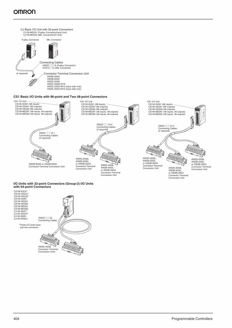
CS1 Basic I/O Units with 96-point and Two 48-point Connectors
I/O Units with 32-point Connectors (Group-2) I/O Units with 64-point Connectors
CJ Basic I/O Unit with 32-point Connectors CJ1W-MD231 (Fujitsu Connector/Input Unit) CJ1W-MD233 (MIL Connector/I/O Unit)
Connecting Cables XW2Z-@@@A (Fujitsu Connector) G79-O@@C (MIL Connector)
Connector-Terminal Conversion Unit XW2B-20G4 XW2B-20G5 XW2D-20G6 XW2C-20G6-IO16 XW2C-20G5-IN16 (input side only) XW2E-20G5-IN16 (input side only)
Fujitsu Connector MIL Connector
(2 required)
CS1 I/O UnitCS1W-ID291 (96 inputs) CS1W-OD291 (96 outputs) CS1W-OD292 (96 outputs) CS1W-MD291 (48 inputs, 48 outputs) CS1W-MD292 (48 inputs, 48 outputs)
XW2Z-@@@H-1 Connecting Cables (2 required)
XW2B-60G4 or XW2B-60G5 Connector-Terminal Conversion Unit
CS1 I/O UnitCS1W-ID291 (96 inputs) CS1W-OD291 (96 outputs) CS1W-OD292 (96 outputs) CS1W-MD291 (48 inputs, 48 outputs) CS1W-MD292 (48 inputs, 48 outputs)
XW2Z-@@@H-2 Connecting Cables (2 required)
XW2D-20G6, XW2B-20G5, or XW2B-20G4 Connector-Terminal Conversion Unit
XW2D-40G6, XW2B-40G5, or XW2B-40G4 Connector-Terminal Conversion Unit
CS1 I/O UnitCS1W-ID291 (96 inputs) CS1W-OD291 (96 outputs) CS1W-OD292 (96 outputs) CS1W-MD291 (48 inputs, 48 outputs) CS1W-MD292 (48 inputs, 48 outputs)
XW2Z-@@@H-3 Connecting Cables (2 required)
XW2D-20G6, XW2B-20G5, or XW2B-20G4 Connector-Terminal Conversion Unit XW2D-20G6,
XW2B-20G5, or XW2B-20G4 Connector-Terminal Conversion Unit
XW2D-20G6, XW2B-20G5, or XW2B-20G4 Connector-Terminal Conversion Unit
CS1W-ID231* CS1W-OD231* CS1W-OD232* CS1W-ID261 CS1W-OD261 CS1W-OD262CS1W-MD261 CS1W-MD262CJ1W-ID231* CJ1W-OD231* CJ1W-ID261 CJ1W-OD261 XW2Z-@@@B
Connecting Cables
XW2D-40G6 Connector-Terminal Conversion Units
*These I/O Units have just one connector.
Y201-EN2-03.book Seite 404 Donnerstag, 30. März 2006 1:52 13

405I/O terminal block
Pro
gra
mm
able
C
on
tro
llers
XW2B
I/O terminal blockEasily wire connectors to Terminal Blocks and Reduce Control Panel Wiring• Can be mounted with screws or snapped onto DIN
rail.• Standard models are available with MIL flat cable
connectors and multipole rectangular connectors.• Terminal Blocks are available with M2.5 or M3.5
screws.• Cables are available for OMRON PLC connectors.
* This is a non-standard model and requires a special order. Contact your OMRON representative for details on availability.
Ratings/Characteristics
Ordering Information
Poles Model20 XW2B-20G534 XW2B-34G5*40 XW2B-40G550 XW2B-50G5*60 XW2B-60G5*20 XW2B-20G434 XW2B-34G4*40 XW2B-40G450 XW2B-50G4*60 XW2B-60G4*
Specifications
Rated current 1 ARated voltage 125 V ACInsulation resistance 100 MΩ min. (at 500 V DC)Dielectric strength 500 V AC for 1 min (with a leakage current
of 1 mA max.)Ambient temperature Operating: −25 to 80 ° C
Y201-EN2-03.book Seite 405 Donnerstag, 30. März 2006 1:52 13

406 Programmable Controllers
Note: All dimensions are in mm.
Dimensions Dimensions
Dimensions
Two, 3.5 dia.
Flat Cable Connector (MIL plug)
Terminal block
Flat Cable Connector (front view)
Terminal Block (front view)
Triangle mark
Connection Diagram
Two, 3.5 dia.
Flat Cable Connector (MIL plug)
Terminal block
Flat Cable Connector (front view)
Terminal Block (front view)
Triangle mark
Connection Diagram
XW2B-@@G5(M3.5 Screws)
XW2B-@@G4(M2.5 Screws)
Model Poles Dimension A (mm)XW2B-20G5 20 112.5XW2B-34G5 34 180.0XW2B-40G5 40 202.5XW2B-50G5 50 247.5XW2B-60G5 60 292.5
Model Poles Dimension A (mm)XW2B-20G4 20 67.5XW2B-34G4 34 112.5XW2B-40G4 40 135.0XW2B-50G4 50 157.5XW2B-60G4 60 180.0
Y201-EN2-03.book Seite 406 Donnerstag, 30. März 2006 1:52 13
407Servo I/O terminal block
Pro
gra
mm
able
C
on
tro
llers
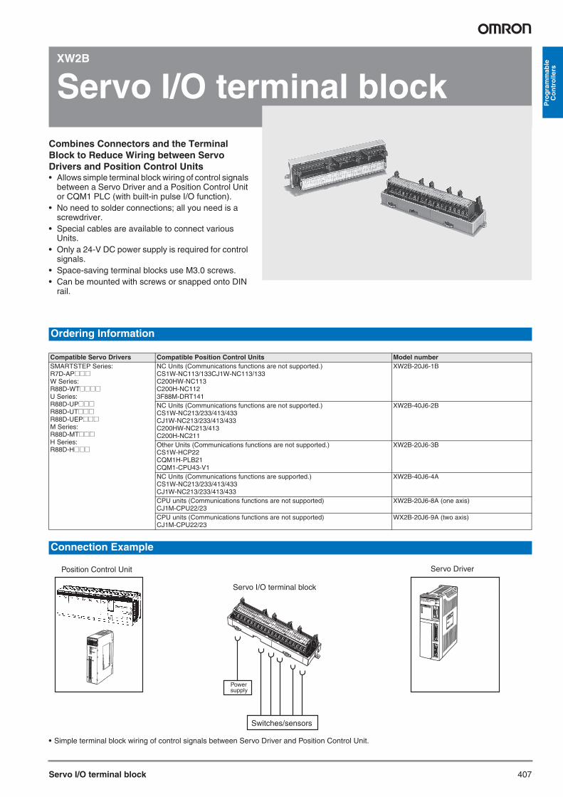
XW2B
Servo I/O terminal blockCombines Connectors and the Terminal Block to Reduce Wiring between Servo Drivers and Position Control Units• Allows simple terminal block wiring of control signals
between a Servo Driver and a Position Control Unit or CQM1 PLC (with built-in pulse I/O function).
• No need to solder connections; all you need is a screwdriver.
• Special cables are available to connect various Units.
• Only a 24-V DC power supply is required for control signals.
• Space-saving terminal blocks use M3.0 screws.• Can be mounted with screws or snapped onto DIN
rail.
• Simple terminal block wiring of control signals between Servo Driver and Position Control Unit.
Ordering Information
Compatible Servo Drivers Compatible Position Control Units Model numberSMARTSTEP Series:R7D-AP@@@W Series:R88D-WT@@@@U Series:R88D-UP@@@R88D-UT@@@R88D-UEP@@@M Series:R88D-MT@@@H Series:R88D-H@@@
NC Units (Communications functions are not supported.)CS1W-NC113/133CJ1W-NC113/133C200HW-NC113C200H-NC1123F88M-DRT141
XW2B-20J6-1B
NC Units (Communications functions are not supported.)CS1W-NC213/233/413/433CJ1W-NC213/233/413/433C200HW-NC213/413C200H-NC211
XW2B-40J6-2B
Other Units (Communications functions are not supported.)CS1W-HCP22CQM1H-PLB21CQM1-CPU43-V1
XW2B-20J6-3B
NC Units (Communications functions are supported.)CS1W-NC213/233/413/433CJ1W-NC213/233/413/433
XW2B-40J6-4A
CPU units (Communications functions are not supported)CJ1M-CPU22/23
XW2B-20J6-8A (one axis)
CPU units (Communications functions are not supported)CJ1M-CPU22/23
WX2B-20J6-9A (two axis)
Connection Example
Position Control Unit Servo Driver
Power supply
Switches/sensors
Servo I/O terminal block
Y201-EN2-03.book Seite 407 Donnerstag, 30. März 2006 1:52 13

408 Programmable Controllers
XW2C
Input terminal blockEquipped with Power Supply Common and Operation Indicators and Reduces Control Panel Wiring to Input Devices• Equipped with a power supply common for input
devices.• Operation indicators show each I/O signal’s ON/
OFF status at a glance.• Can be mounted on DIN rail or screw-mounted.• Compatible Connecting Cables are available (sold
separately.)
This is a non-standard model and requires a special order. Contact your OMRON representative for details on availability.
Ratings/Characteristics
Note: All dimensions are in mm. XW2C-20G5-IN16
Ordering Information
Points Internal I/O circuit common
Model
16 inputs NPN compatible (+ common)
XW2C-20G5-IN16
Specifications
Rated current 1 A/commonRated voltage 12 to 24 V DCNumber of circuits 16 pointsInput display LED indicators (orange)Power supply voltage range 12 to 24 V DC ±5%LED indicator current 10 mA/input max. at 24 V DCInsulation resistance 50 MΩ min. (at 500 V DC)Dielectric strength 500 V AC for 1 minAmbient temperature Operating: 0 to 55 ° C
Dimensions
Two, 4.5 dia.
Flat Cable Connector (MIL plug)
DIN Track lockTerminal block
Y201-EN2-03.book Seite 408 Donnerstag, 30. März 2006 1:52 13

409Slim Input terminal block
Pro
gra
mm
able
C
on
tro
llers
XW2D
Slim Input terminal blockIntroducing the XW2D Series, a Slim Version of the I/O terminal block• Required mounting area reduced by 35% (com-
pared to OMRON’s 40-pole XW2B Unit), allowing for smaller control panels and automatic equipment.
• Terminal screw mechanism prevents lost terminal screws.
• Use either round or forked crimp terminals.• Mount via DIN rail or screws. Unique DIN rail lock to
mount or remove Units from DIN rail while open.• Terminal cover can be fixed in the open position.• Easy-count terminal numbers with different colors
every five terminals.
Note: 1. Has a built-in bleeder resistor and is for the CJ1W-ID231/ID261. External dimensions are the same as the XW2D-40G6.2. Has a built-in bleeder resistor and is for the CJ1W-ID232. External dimensions are the same as the XW2D-40G6.3. The MR Connectors are manufactured by Honda Tsushin Kogyou Co., Ltd.
Ratings /Characteristics
Ordering Information
Mounted connec-tor
Poles Model Dimension A Dimension B Mounted connector model
Cable connector model
MIL, XG4A 20 XW2D-20G6 79 57 XG4A-2031 XG4M-2030-T34 XW2D-34G6* 128 100 XG4A-3431 XG4M-3430-T40 XW2D-40G6 149 110 XG4A-4031 XG4M-4030-T
XW2D-40G6-RF* (See note 1.) 149 110 XG4A-4031 XG4M-4030-TXW2D-40G6-RM* (See note 2.) 149 110 XG4A-4031 XG4M-4030-T
50 XW2D-50G6* 184 144 XG4A-5031 XG4M-5030-TMIL, XG4C 20 XW2D-20C6* 79 57 XG4C-2031 XG4M-2030-U
34 XW2D-34C6* 128 100 XG4C-3431 XG4M-3430-U40 XW2D-40C6* 149 110 XG4C-4031 XG4M-4030-U50 XW2D-50C6* 184 144 XG4C-5031 XG4M-5030-U
MR Socket(See note 3.)
20 XW2D-20X6* 79 57 MR-20RFD2 MR-20M34 XW2D-34X6* 128 100 MR-34RFD2 MR-34M50 XW2D-50X6* 184 144 MR-50RFD2 MR-50M
MR Plug(See note 3.)
20 XW2D-20Y6* 79 57 MR-20RMD2 MR-20F34 XW2D-34Y6* 128 100 MR-34RMD2 MR-34F50 XW2D-50Y6* 184 144 MR-50RMD2 MR-50F
Specifications
Rated current 1 ARated voltage 125 V AC, 24 V DCInsulation resistance 100 MΩ max. (at 500 V DC)Dielectric strength 500 V AC for 1 min (with a leakage
current of 1 mA max.)Ambient temperature Operating: 0 to 55 ° C
Y201-EN2-03.book Seite 409 Donnerstag, 30. März 2006 1:52 13
410 Programmable Controllers
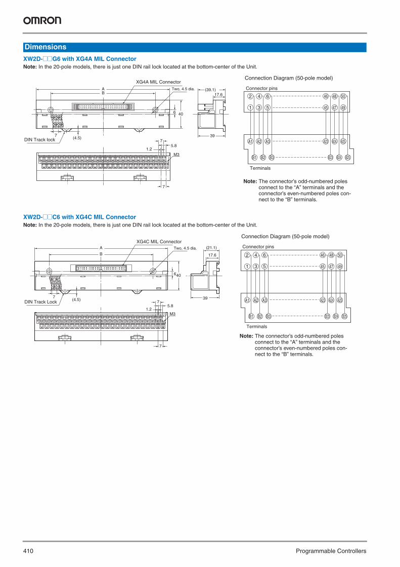
XW2D-@@G6 with XG4A MIL ConnectorNote: In the 20-pole models, there is just one DIN rail lock located at the bottom-center of the Unit.
XW2D-@@C6 with XG4C MIL ConnectorNote: In the 20-pole models, there is just one DIN rail lock located at the bottom-center of the Unit.
Dimensions
AB
6 40
(4.5)7 39
(39.1)17.6
7
7
M3
5.81.2
Two, 4.5 dia.
XG4A MIL Connector
DIN Track lock
2 4 6 46 48 50
A23 A24 A25
B23 B24 B25
45 47 491 3 5
A1 A2 A3
B1 B2 B3
Connection Diagram (50-pole model)
Connector pins
Terminals
Note: The connector’s odd-numbered poles connect to the “A” terminals and the connector’s even-numbered poles con-nect to the “B” terminals.
17.6
39
(21.1)
B
640
(4.5)7
A
7
1.2
75.8
M3
Two, 4.5 dia.
XG4C MIL Connector
DIN Track Lock
2 4 6 46 48 50
A23 A24 A25
B23 B24 B25
45 47 491 3 5
A1 A2 A3
B1 B2 B3
Connection Diagram (50-pole model)
Connector pins
Terminals
Note: The connector’s odd-numbered poles connect to the “A” terminals and the connector’s even-numbered poles con-nect to the “B” terminals.
Y201-EN2-03.book Seite 410 Donnerstag, 30. März 2006 1:52 13

Slim Input terminal block 411
Pro
gra
mm
able
C
on
tro
llers
XW2D-@@X6 with MR Socket ConnectorNote: In the 20-pole models, there is just one DIN rail lock located at the bottom-center of the Unit.
XW2D-@@Y6 with MR Plug ConnectorNote: In the 20-pole models, there is just one DIN rail lock located at the bottom-center of the Unit.
39
(28.2)
17.6AB
6 40
(4.5)7
7
7
M3
5.81.2
Two, 4.5 dia.
DIN Track Lock
33 34 35 48 49 50
45 47 49
46 48 50
16 17 18
19 20 32
1 2 3
1 3 5
2 4 6
17 19
16 18 20
Connection Diagram (50-pole model)
Connector pins
Terminals
Note: The connector’s poles connect to the MR socket terminals with the same number.
(4.5)7 39
(25.9)17.6
AB
6 40
7
7
M3
5.81.2
Two, 4.5 dia.
DIN Track Lock
1 2 3
19
33 34 35
20 32
16 1817
48 50
504846
45 47171 3 5
2 4 6
19
201816
49
49
Connection Diagram (50-pole model)
Connector pins
Terminals
Note: The pin numbers on the connector cor-respond directly to the terminal num-bers on the terminal block.
Y201-EN2-03.book Seite 411 Donnerstag, 30. März 2006 1:52 13

412 Programmable Controllers
XW2Z
Connecting Cables for I/O terminal blocks
• Refer to page 416 for connection details.
Ordering Information
XW2Z-@@@A XW2Z-@@@AU (See note.)
XW2Z-@@@B XW2Z-@@@BU (See note.)
XW2Z-@@@D
* This is a non-standard model and requires a special order. Contact your OMRON representative for details on availability.
XW2Z-@@@A Cables for PLC Units with 32-point Connectors
*Cable length L (mm) Model500 mm XW2Z-050A1,000 mm XW2Z-100A1,500 mm XW2Z-150A*2,000 mm XW2Z-200A3,000 mm XW2Z-300A*5,000 mm XW2Z-500A*
L
*Cable length (mm)
*Cable length L (mm) Model500 mm XW2Z-050AU*1,000 mm XW2Z-100AU*1,500 mm XW2Z-150AU*2,000 mm XW2Z-200AU*3,000 mm XW2Z-300AU*5,000 mm XW2Z-500AU*
L
*Cable length (mm)
XW2Z-@@@B Cables for Group-2 PLC I/O Units with 32-point Connectors and PLC I/O Units with 64-point Connectors
Wiring *Cable length L (mm) ModelNormal wiring 500 mm XW2Z-050B
1,000 mm XW2Z-100B1,500 mm XW2Z-150B*2,000 mm XW2Z-200B3,000 mm XW2Z-300B5,000 mm XW2Z-500B
L
*Cable length (mm)
Wiring *Cable length L (mm) ModelNormal wiring 500 mm XW2Z-050BU*
1,000 mm XW2Z-100BU*1,500 mm XW2Z-150BU*2,000 mm XW2Z-200BU*3,000 mm XW2Z-300BU*5,000 mm XW2Z-500BU*
L
*Cable length (mm)
XW2Z-@@@D Cables for Group-2 PLC Input Units with 32-point Connectors and PLC Input Units with 64-point Connectors
Note: The wiring of the G79-I@C-@ cables (for the G7TC) is different, so these cables cannot be used with the XW2C.
A
B
A20
A1 B1
B20 CN3(250)
CN2(500)
*Cable length (mm) RowA
Yellow
Black
The pins in CN2 (yellow) connect to row A of CN1 and the pins in CN3 (black) connect to row B of CN1.
RowB
*Cable lengths (mm) ModelA B1,000 mm 750 mm XW2Z-100D*1,500 mm 1,250 mm XW2Z-150D*2,000 mm 1,750 mm XW2Z-200D*3,000 mm 2,750 mm XW2Z-300D*5,000 mm 4.750 mm XW2Z-500D*
Y201-EN2-03.book Seite 412 Donnerstag, 30. März 2006 1:52 13

Connecting Cables for I/O terminal blocks 413
Pro
gra
mm
able
C
on
tro
llers
XW2Z-@@@F
These are all non-standard model and require a special order. Contact your OMRON representative for details on availability.
XW2Z-@@@L
These are all non-standard model and require a special order. Contact your OMRON representative for details on availability.
XW2Z-@@@H-1
These are all non-standard model and require a special order. Contact your OMRON representative for details on availability.
XW2Z-@@@H-2
These are all non-standard model and require a special order. Contact your OMRON representative for details on availability.
XW2Z-@@@F Cables with Crimp Terminals (20 poles)
L300
XG4M-2030-T
*Cable length (mm)
Fork Terminals(M3.5)
Connectto devices
*Cable length L (mm) Model1,000 mm XW2Z-100F1,500 mm XW2Z-150F2,000 mm XW2Z-200F3,000 mm XW2Z-300F5,000 mm XW2Z-500F
XW2Z-@@@L Cables for Group-2 PLC Output Units with 32-point Connectors and PLC Output Units with 64-point Connectors
A
B
CN3(250)
CN2(500)
A20
A1 B1
B20
*Cable lengths (mm) RowA
Green
White
The pins in CN2 (white) connect to row A of CN1 and the pins in CN3 (green) connect to row B of CN1.
RowB
*Cable lengths (mm) ModelA B1,000 mm 750 mm XW2Z-100L1,500 mm 1,250 mm XW2Z-150L2,000 mm 1,750 mm XW2Z-200L3,000 mm 2,750 mm XW2Z-300L5,000 mm 4.750 mm XW2Z-500L
XW2Z-@@@H Cables for PLC I/O Units with 96-point Connectors
Cable length (mm) Model500 mm XW2Z-050H-11,000 mm XW2Z-100H-11,500 mm XW2Z-150H-12,000 mm XW2Z-200H-13,000 mm XW2Z-300H-15,000 mm XW2Z-500H-17,000 mm XW2Z-700H-110,000 mm XW2Z-010H-1
L
*Cable length (mm)
Cable lengths (mm) ModelA B1,000 mm 750 mm XW2Z-100H-21,500 mm 1,250 mm XW2Z-150H-22,000 mm 1,750 mm XW2Z-200H-23,000 mm 2,750 mm XW2Z-300H-25,000 mm 4.750 mm XW2Z-500H-210,000 mm 9,750 mm XW2Z-010H-2
CN2
CN3
CN1
A
B
*Cable lengths (mm)
Wiring distance(not including bends)
Yellow
Black
Y201-EN2-03.book Seite 413 Donnerstag, 30. März 2006 1:52 13

414 Programmable Controllers
XW2Z-@@@H-3
These are all non-standard model and require a special order. Contact your OMRON representative for details on availability.
XW2Z-@@@K
* This is a non-standard model and requires a special order. Contact your OMRON representative for details on availability.
XW2Z-@@@N
These are all non-standard model and require a special order. Contact your OMRON representative for details on availability.
CN2
CN3
CN4
CN1
Gray
*Cable lengths (mm)
Wiring distance(not including bends)
Yellow
Black
A
C
B
Cable lengths (mm) ModelA B C1,000 mm 750 mm 1,000 mm XW2Z-100H-31,500 mm 1,250 mm 1,500 mm XW2Z-150H-32,000 mm 1,750 mm 2,000 mm XW2Z-200H-33,000 mm 2,750 mm 3,000 mm XW2Z-300H-35,000 mm 4.750 mm 5,000 mm XW2Z-500H-310,000 mm 9,750 mm 10,000 mm XW2Z-010H-3
XW2Z-@@@K/N Cables for PLC I/O Units with 32-point MIL Connectors
L
*Cable length (mm)
Cable length (mm) Model (See note.)1,000 mm XW2Z-100K1,500 mm XW2Z-150K*2,000 mm XW2Z-200K3,000 mm XW2Z-300K*5,000 mm XW2Z-500K*
(120)
A
B
*Cable lengths (mm)
Wiring distance(not including bends)
Cable lengths (mm) ModelA B1,000 mm 750 mm XW2Z-100N1,500 mm 1,250 mm XW2Z-150N2,000 mm 1,750 mm XW2Z-200N3,000 mm 2,750 mm XW2Z-300N5,000 mm 4.750 mm XW2Z-500N
Y201-EN2-03.book Seite 414 Donnerstag, 30. März 2006 1:52 13

415Host Link Cables
Pro
gra
mm
able
C
on
tro
llers
XW2Z
Host Link Cables
PLC-compatible RS-232C Cables Ideal for Host Link Connections between a PLC and Host Computer or other Device
Note: 1. The cable length does not include the connectors, as shown in the following diagram.
* This is a non-standard model and requires a special order. Contact your OMRON representative for details on availability.
Ordering Information
SYSMAC PLC end XW2Z Host Link Cable (PLC-compatible RS-232C cable) Host device endWiring configuration Cable length L
(See note 1.)Model number
CS1@-CPU@@CJ1@-CPU@@CPM2A-CPU@@
2 m XW2Z-200S-V Personal Computer5 m XW2Z-500S-V*
2 m XW2Z-200S-CV*5 m XW2Z-500S-CV*
CS1@-CPU@@CJ1@-CPU@@CPM2A-CPU@@
2 m XW2Z-200T Programmable Terminal:NT20S, NT600S, NT620S, NT620C, NT30, or NT30CNT31, or NT31C, NT631, or NT 631 C, NS-series
5 m XW2Z-500T
SD 23456
RDRSCS
11RD2
3456
SDERSGDR
7 7 RS8 8 CS9SG 9
---
---------
---
---
Connector hood FGPLC end
9-pin D-Sub Plug
Connector hood FGHost end
9-pin D-Sub Socket
Shield
FGSD 2
3456
RDRSCS
11RD2
3456
SDERSGDR
7DR 7 RS8ER 8 CS9SG 9
---
---
---
Connector hood FGPLC end
9-pin D-Sub Plug
Connector hood FGHost end
9-pin D-Sub Socket
Shield
ESD-preventive connectors are used.
SD 23459
RDRSCSSG
11SD2
3459
RDRSCSSG
--- ---Connector hood FG
PLC end
9-pin D-Sub Plug
Connector hood FGHost end
9-pin D-Sub Plug
Shield
L
Cable length
Y201-EN2-03.book Seite 415 Donnerstag, 30. März 2006 1:52 13

416 Programmable Controllers
I/O Connecting Cable Selection guideConnecting to CS1 I/O Units
I/O Unit model
Connector-Terminal Conversion Unit or I/O Block model
Connecting CableBranch-ing
Length (m)
Model Page
CS1W-ID291 (48 points x 2)
XW2B-60G5XW2B-60G4
1:1 0.5 XW2Z-050H-1 4131 XW2Z-100H-11.5 XW2Z-150H-12 XW2Z-200H-13 XW2Z-300H-15 XW2Z-500H-17 XW2Z-700H-110 XW2Z-010H-1
XW2D-20G6 + XW2D-40G6XW2B-20G5 + XW2B-40G5XW2B-20G4 + XW2B-40G4
1:2 1 XW2Z-100H-21.5 XW2Z-150H-22 XW2Z-200H-23 XW2Z-300H-25 XW2Z-500H-210 XW2Z-010H-2
XW2D-20G6 (3 Units)XW2B-20G5 (3 Units)XW2B-20G4 (3 Units)
1:3 1 XW2Z-100H-31.5 XW2Z-150H-32 XW2Z-200H-33 XW2Z-300H-35 XW2Z-500H-310 XW2Z-010H-3
G7TC-IA16/ID16 1:3 1.5 G79-150C-125-100
402
2 G79-200C-175-150
3 G79-300C-275-250
CS1W-OD291 (48 points × 2)
XW2B-60G5XW2B-60G4
1:1 0.5 XW2Z-050H-1 4131 XW2Z-100H-11.5 XW2Z-150H-12 XW2Z-200H-13 XW2Z-300H-15 XW2Z-500H-17 XW2Z-700H-110 XW2Z-010H-1
XW2D-20G6 + XW2D-40G6XW2B-20G5 + XW2B-40G5XW2B-20G4 + XW2B-40G4
1:2 1 XW2Z-100H-21.5 XW2Z-150H-22 XW2Z-200H-23 XW2Z-300H-25 XW2Z-500H-210 XW2Z-010H-2
XW2D-20G6 (3 Units)XW2B-20G5 (3 Units)XW2B-20G4 (3 Units)
1:3 1 XW2Z-100H-31.5 XW2Z-150H-32 XW2Z-200H-33 XW2Z-300H-35 XW2Z-500H-310 XW2Z-010H-3
G7TC-OC16/08G70D-SOC16/VSOC16G70A-ZOC16-3
1:3 1.5 G79-150C-125-100
402
2 G79-200C-175-150
3 G79-300C-275-250
CS1W-OD292 (48 points × 2)
XW2B-60G5XW2B-60G4
1:1 0.5 XW2Z-050H-1 4131 XW2Z-100H-11.5 XW2Z-150H-12 XW2Z-200H-13 XW2Z-300H-15 XW2Z-500H-17 XW2Z-700H-110 XW2Z-010H-1
XW2D-20G6 + XW2D-40G6XW2B-20G5 + XW2B-40G5XW2B-20G4 + XW2B-40G4
1:2 1 XW2Z-100H-21.5 XW2Z-150H-22 XW2Z-200H-23 XW2Z-300H-25 XW2Z-500H-210 XW2Z-010H-2
XW2D-20G6 (3 Units)XW2B-20G5 (3 Units)XW2B-20G4 (3 Units)
1:3 1 XW2Z-100H-31.5 XW2Z-150H-32 XW2Z-200H-33 XW2Z-300H-35 XW2Z-500H-310 XW2Z-010H-3
G7TC-OC16-1 1:3 1.5 G79-150C-125-100
402
2 G79-200C-175-150
3 G79-300C-275-250
CS1W-MD291(48 inputs)(48 outputs)
XW2B-60G5XW2B-60G4
1:1 0.5 XW2Z-050H-1 4131 XW2Z-100H-11.5 XW2Z-150H-12 XW2Z-200H-13 XW2Z-300H-15 XW2Z-500H-17 XW2Z-700H-110 XW2Z-010H-1
XW2D-20G6 + XW2D-40G6XW2B-20G5 + XW2B-40G5XW2B-20G4 + XW2B-40G4
1:2 1 XW2Z-100H-21.5 XW2Z-150H-22 XW2Z-200H-23 XW2Z-300H-25 XW2Z-500H-210 XW2Z-010H-2
XW2D-20G6 (3 Units)XW2B-20G5 (3 Units)XW2B-20G4 (3 Units)
1:3 1 XW2Z-100H-31.5 XW2Z-150H-32 XW2Z-200H-33 XW2Z-300H-35 XW2Z-500H-310 XW2Z-010H-3
G7TC-IA16/ID16G7TC-OC16/08G70D-SOC16/VSOC16G70A-ZOC16-3
1:3 1.5 G79-150C-125-100
402
2 G79-200C-175-150
3 G79-300C-275-250
I/O Unit model
Connector-Terminal Conversion Unit or I/O Block model
Connecting CableBranch-ing
Length (m)
Model Page
Connecting_Cable.fm Seite 416 Mittwoch, 12. April 2006 12:22 12

417
Pro
gra
mm
able
C
on
tro
llers
CS1W-MD292(48 inputs)(48 outputs)
XW2B-60G5XW2B-60G4
1:1 0.5 XW2Z-050H-1 4131 XW2Z-100H-11.5 XW2Z-150H-12 XW2Z-200H-13 XW2Z-300H-15 XW2Z-500H-17 XW2Z-700H-110 XW2Z-010H-1
XW2D-20G6 + XW2D-40G6XW2B-20G5 + XW2B-40G5XW2B-20G4 + XW2B-40G4
1:2 1 XW2Z-100H-21.5 XW2Z-150H-22 XW2Z-200H-23 XW2Z-300H-25 XW2Z-500H-210 XW2Z-010H-2
XW2D-20G6 (3 Units)XW2B-20G5 (3 Units)XW2B-20G4 (3 Units)
1:3 1 XW2Z-100H-31.5 XW2Z-150H-32 XW2Z-200H-33 XW2Z-300H-35 XW2Z-500H-310 XW2Z-010H-3
G7TC-IA16/ID16G7TC-OC16-1
1:3 1.5 G79-150C-125-100
402
2 G79-200C-175-150
3 G79-300C-275-250
CS1W-ID231 (32 points)
XW2D-40G6XW2B-40G5XW2B-40G4
1:1 0.5 XW2Z-050B 4121 XW2Z-100B1.5 XW2Z-150B2 XW2Z-200B3 XW2Z-300B5 XW2Z-500B
XW2D-40C6 1:1 0.5 XW2Z-050BU1 XW2Z-100BU1.5 XW2Z-150BU2 XW2Z-200BU3 XW2Z-300BU5 XW2Z-500BU
XW2D-20G6 (2 Units)XW2B-20G5 (2 Units)XW2B-20G4 (2 Units)XW2B-40G5-TXW2C-20G6-IO16 (2 Units)XW2C-20G5-IN16 (2 Units)XW2E-20G5-IN16 (2 Units)
1:2 1 XW2Z-100D1.5 XW2Z-150D2 XW2Z-200D3 XW2Z-300D5 XW2Z-500D
CS1W-OD231 (32 points)
XW2D-40G6XW2B-40G5XW2B-40G4
1:1 0.5 XW2Z-050B 4121 XW2Z-100B1.5 XW2Z-150B2 XW2Z-200B3 XW2Z-300B5 XW2Z-500B
XW2D-40C6 1:1 0.5 XW2Z-050BU1 XW2Z-100BU1.5 XW2Z-150BU2 XW2Z-200BU3 XW2Z-300BU5 XW2Z-500BU
XW2D-20G6 (2 Units)XW2B-20G5 (2 Units)XW2B-20G4 (2 Units)XW2B-40G5-TXW2C-20G6-IO16 (2 Units)
1:2 1 XW2Z-100L 4131.5 XW2Z-150L2 XW2Z-200L3 XW2Z-300L5 XW2Z-500L
I/O Unit model
Connector-Terminal Conversion Unit or I/O Block model
Connecting CableBranch-ing
Length (m)
Model Page
CS1W-OD232 (32 points)
XW2D-40G6XW2B-40G5XW2B-40G4
1:1 0.5 XW2Z-050B 4121 XW2Z-100B1.5 XW2Z-150B2 XW2Z-200B3 XW2Z-300B5 XW2Z-500B
XW2D-40C6 1:1 0.5 XW2Z-050BU1 XW2Z-100BU1.5 XW2Z-150BU2 XW2Z-200BU3 XW2Z-300BU5 XW2Z-500BU
XW2D-20G6 (2 Units)XW2B-20G5 (2 Units)XW2B-20G4 (2 Units)XW2B-40G5-TXW2C-20G6-IO16 (2 Units)
1:2 1 XW2Z-100L 4131.5 XW2Z-150L2 XW2Z-200L3 XW2Z-300L5 XW2Z-500L
CS1W-ID261 (32 points × 2)
XW2D-40G6XW2B-40G5XW2B-40G4
1:1 0.5 XW2Z-050B 4121 XW2Z-100B1.5 XW2Z-150B2 XW2Z-200B3 XW2Z-300B5 XW2Z-500B
XW2D-40C6 1:1 0.5 XW2Z-050BU1 XW2Z-100BU1.5 XW2Z-150BU2 XW2Z-200BU3 XW2Z-300BU5 XW2Z-500BU
XW2D-20G6 (2 Units)XW2B-20G5 (2 Units)XW2B-20G4 (2 Units)XW2B-40G5-TXW2C-20G6-IO16 (2 Units)XW2C-20G5-IN16 (2 Units)XW2E-20G5-IN16 (2 Units)
1:2 1 XW2Z-100D1.5 XW2Z-150D2 XW2Z-200D3 XW2Z-300D5 XW2Z-500D
CS1W-OD261 (32 points × 2)
XW2D-40G6XW2B-40G5XW2B-40G4
1:1 0.5 XW2Z-050B 4121 XW2Z-100B1.5 XW2Z-150B2 XW2Z-200B3 XW2Z-300B5 XW2Z-500B
XW2D-40C6 1:1 0.5 XW2Z-050BU1 XW2Z-100BU1.5 XW2Z-150BU2 XW2Z-200BU3 XW2Z-300BU5 XW2Z-500BU
XW2D-20G6 (2 Units)XW2B-20G5 (2 Units)XW2B-20G4 (2 Units)XW2B-40G5-TXW2C-20G6-IO16 (2 Units)
1:2 1 XW2Z-100L 4121.5 XW2Z-150L2 XW2Z-200L3 XW2Z-300L5 XW2Z-500L
CS1W-OD262 (32 points × 2)
XW2D-40G6XW2B-40G5XW2B-40G4
1:1 0.5 XW2Z-050B 4131 XW2Z-100B1.5 XW2Z-150B2 XW2Z-200B3 XW2Z-300B5 XW2Z-500B
XW2D-40C6 1:1 0.5 XW2Z-050BU1 XW2Z-100BU1.5 XW2Z-150BU2 XW2Z-200BU3 XW2Z-300BU5 XW2Z-500BU
XW2D-20G6 (2 Units)XW2B-20G5 (2 Units)XW2B-20G4 (2 Units)XW2B-40G5-TXW2C-20G6-IO16 (2 Units)
1:2 1 XW2Z-100L 4131.5 XW2Z-150L2 XW2Z-200L3 XW2Z-300L5 XW2Z-500L
I/O Unit model
Connector-Terminal Conversion Unit or I/O Block model
Connecting CableBranch-ing
Length (m)
Model Page
Connecting_Cable.fm Seite 417 Mittwoch, 12. April 2006 12:22 12
418 Programmable Controllers
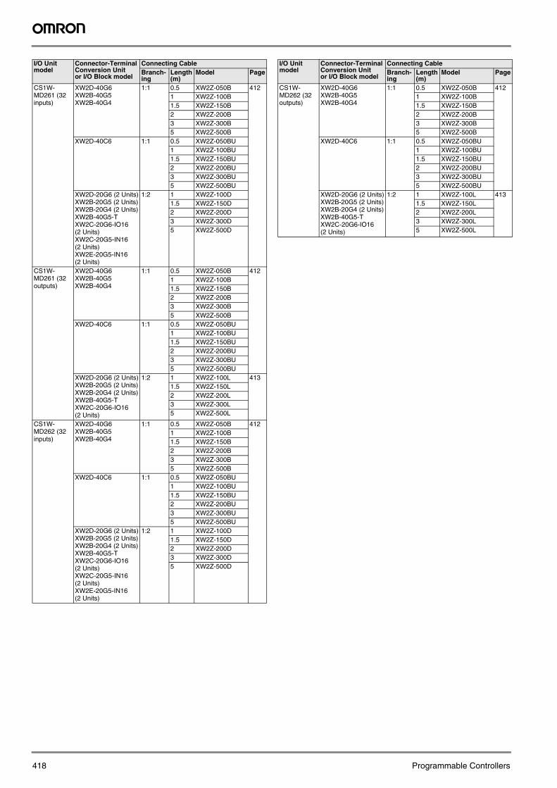
CS1W-MD261 (32 inputs)
XW2D-40G6XW2B-40G5XW2B-40G4
1:1 0.5 XW2Z-050B 4121 XW2Z-100B1.5 XW2Z-150B2 XW2Z-200B3 XW2Z-300B5 XW2Z-500B
XW2D-40C6 1:1 0.5 XW2Z-050BU1 XW2Z-100BU1.5 XW2Z-150BU2 XW2Z-200BU3 XW2Z-300BU5 XW2Z-500BU
XW2D-20G6 (2 Units)XW2B-20G5 (2 Units)XW2B-20G4 (2 Units)XW2B-40G5-TXW2C-20G6-IO16 (2 Units)XW2C-20G5-IN16 (2 Units)XW2E-20G5-IN16 (2 Units)
1:2 1 XW2Z-100D1.5 XW2Z-150D2 XW2Z-200D3 XW2Z-300D5 XW2Z-500D
CS1W-MD261 (32 outputs)
XW2D-40G6XW2B-40G5XW2B-40G4
1:1 0.5 XW2Z-050B 4121 XW2Z-100B1.5 XW2Z-150B2 XW2Z-200B3 XW2Z-300B5 XW2Z-500B
XW2D-40C6 1:1 0.5 XW2Z-050BU1 XW2Z-100BU1.5 XW2Z-150BU2 XW2Z-200BU3 XW2Z-300BU5 XW2Z-500BU
XW2D-20G6 (2 Units)XW2B-20G5 (2 Units)XW2B-20G4 (2 Units)XW2B-40G5-TXW2C-20G6-IO16 (2 Units)
1:2 1 XW2Z-100L 4131.5 XW2Z-150L2 XW2Z-200L3 XW2Z-300L5 XW2Z-500L
CS1W-MD262 (32 inputs)
XW2D-40G6XW2B-40G5XW2B-40G4
1:1 0.5 XW2Z-050B 4121 XW2Z-100B1.5 XW2Z-150B2 XW2Z-200B3 XW2Z-300B5 XW2Z-500B
XW2D-40C6 1:1 0.5 XW2Z-050BU1 XW2Z-100BU1.5 XW2Z-150BU2 XW2Z-200BU3 XW2Z-300BU5 XW2Z-500BU
XW2D-20G6 (2 Units)XW2B-20G5 (2 Units)XW2B-20G4 (2 Units)XW2B-40G5-TXW2C-20G6-IO16 (2 Units)XW2C-20G5-IN16 (2 Units)XW2E-20G5-IN16 (2 Units)
1:2 1 XW2Z-100D1.5 XW2Z-150D2 XW2Z-200D3 XW2Z-300D5 XW2Z-500D
I/O Unit model
Connector-Terminal Conversion Unit or I/O Block model
Connecting CableBranch-ing
Length (m)
Model Page
CS1W-MD262 (32 outputs)
XW2D-40G6XW2B-40G5XW2B-40G4
1:1 0.5 XW2Z-050B 4121 XW2Z-100B1.5 XW2Z-150B2 XW2Z-200B3 XW2Z-300B5 XW2Z-500B
XW2D-40C6 1:1 0.5 XW2Z-050BU1 XW2Z-100BU1.5 XW2Z-150BU2 XW2Z-200BU3 XW2Z-300BU5 XW2Z-500BU
XW2D-20G6 (2 Units)XW2B-20G5 (2 Units)XW2B-20G4 (2 Units)XW2B-40G5-TXW2C-20G6-IO16 (2 Units)
1:2 1 XW2Z-100L 4131.5 XW2Z-150L2 XW2Z-200L3 XW2Z-300L5 XW2Z-500L
I/O Unit model
Connector-Terminal Conversion Unit or I/O Block model
Connecting CableBranch-ing
Length (m)
Model Page
Connecting_Cable.fm Seite 418 Mittwoch, 12. April 2006 12:22 12

419
Pro
gra
mm
able
C
on
tro
llers
Connecting to CJ1 I/O Units
I/O Unit model
Connector-Terminal Conversion Unit or I/O Block model
Connecting CableBranch-ing
Length (m)
Model Page
CJ1W-ID231 (32 points)
XW2D-40G6XW2D-40G6-RFXW2B-40G5XW2B-40G4
1:1 0.5 XW2Z-050B 4121 XW2Z-100B1.5 XW2Z-150B2 XW2Z-200B3 XW2Z-300B5 XW2Z-500B
XW2D-40C6 1:1 0.5 XW2Z-050BU1 XW2Z-100BU1.5 XW2Z-150BU2 XW2Z-200BU3 XW2Z-300BU5 XW2Z-500BU
XW2D-20G6 (2 Units)XW2B-20G5 (2 Units)XW2B-20G4 (2 Units)XW2B-40G5-TXW2C-20G6-IO16 (2 Units)XW2C-20G5-IN16 (2 Units)XW2E-20G5-IN16 (2 Units)
1:2 1 XW2Z-100D1.5 XW2Z-150D2 XW2Z-200D3 XW2Z-300D5 XW2Z-500D
G7TC-IA16/ID16 1:2 1 G79-I100C-75 4011.5 G79-I150C-1252 G79-I200C-1753 G79-I300C-2755 G79-I500C-475
CJ1W-OD231 (32 points)
XW2D-40G6XW2B-40G5XW2B-40G4
1:1 0.5 XW2Z-050B 4121 XW2Z-100B1.5 XW2Z-150B2 XW2Z-200B3 XW2Z-300B5 XW2Z-500B
XW2D-40C6 1:1 0.5 XW2Z-050BU1 XW2Z-100BU1.5 XW2Z-150BU2 XW2Z-200BU3 XW2Z-300BU5 XW2Z-500BU
XW2D-20G6 (2 Units)XW2B-20G5 (2 Units)XW2B-20G4 (2 Units)XW2B-40G5-TXW2C-20G6-IO16 (2 Units)
1:2 1 XW2Z-100L 4131.5 XW2Z-150L2 XW2Z-200L3 XW2Z-300L5 XW2Z-500L
G7TC-OC16/08G70D-SOC16/VSOC16G70A-ZOC16-3
1:2 1 G79-O100C-75 4011.5 G79-O150C-
1252 G79-O200C-
1753 G79-O300C-
2755 G79-O500C-
475CJ1W-ID232 (32 points)
XW2D-40G6XW2D-40G6-RMXW2B-40G5XW2B-40G4
1:1 1 XW2Z-100K 4141.5 XW2Z-150K2 XW2Z-200K3 XW2Z-300K5 XW2Z-500K
XW2D-20G6 (2 Units)XW2B-20G5 (2 Units)XW2B-20G4 (2 Units)XW2B-40G5-TXW2C-20G6-IO16 (2 Units)XW2C-20G5-IN16 (2 Units)XW2E-20G5-IN16 (2 Units)
1:2 1 XW2Z-100N1.5 XW2Z-150N2 XW2Z-200N3 XW2Z-300N5 XW2Z-500N
CJ1W-OD232 (32 points)
XW2D-40G6XW2B-40G5XW2B-40G4
1:1 1 XW2Z-100K 4141.5 XW2Z-150K2 XW2Z-200K3 XW2Z-300K5 XW2Z-500K
XW2D-20G6 (2 Units)XW2B-20G5 (2 Units)XW2B-20G4 (2 Units)XW2B-40G5-TXW2C-20G6-IO16 (2 Units)
1:2 1 XW2Z-100N1.5 XW2Z-150N2 XW2Z-200N3 XW2Z-300N5 XW2Z-500N
CJ1W-OD233(32 points)
XW2D-40G6XW2B-40G5XW2B-40G4
1:1 1 XW2Z-100K 4141,5 XW2Z-150K2 XW2Z-200K3 XW2Z-300K5 XW2Z-500K
XW2D-20G6 (2 units) 1:2 1 XW2Z-100N 414XW2B-20G5 (2 units) 1,5 XW2Z-150NXW2B-20G4 (2units) 2 XW2Z-200NXW2B-40G5-T 3 XW2Z-300NXW2C-20G6-IO16 (2 units)
5 XW2Z-500N
CJ1W-MD231(16 inputs)
XW2D-20G6 1:1 0,5 XW2Z-050A 412XW2B-20G5 1 XW2Z-100AXW2B-20G4 1,5 XW2Z-150AXW2C-20G6-IO16 2 XW2Z-200AXW2C-20G5-IN16 3 XW2Z-300AXW2E-20G5-IN16 5 XW2Z-500AXW2D-20C6 1:1 0,5 XW2Z-050AU 412
1 XW2Z-100AU1,5 XW2Z-150AU2 XW2Z-200AU3 XW2Z-300AU5 XW2Z-500AU
CJ1W-MD231(16 outputs)
XW2D-20G6 1:1 0,5 XW2Z-050A 412XW2B-20G5 1 XW2Z-100AXW2B-20G4 1,5 XW2Z-150AXW2C-20G6-IO16 2 XW2Z-200A
3 XW2Z-300A5 XW2Z-500A
XW2D-20C6 1:1 0,5 XW2Z-050AU 4121 XW2Z-100AU1,5 XW2Z-150AU2 XW2Z-200AU3 XW2Z-300AU5 XW2Z-500AU
CJ1W-MD233(16 inputs)
XW2D-20G6 1:1 0,25 G79-O25C 401XW2B-20G5 0,5 G79-O50CXW2B-20G4XW2C-20G6-IO16XW2C-20G5-IN16XW2E-20G5-IN16
CJ1W-MD233(16 outputs)
XW2D-20G6 1:1 0,25 G79-O25C 401XW2B-20G5 0,5 G79-O50CXW2B-20G4XW2C-20G6-IO16
I/O Unit model
Connector-Terminal Conversion Unit or I/O Block model
Connecting CableBranch-ing
Length (m)
Model Page
Connecting_Cable.fm Seite 419 Mittwoch, 12. April 2006 12:22 12

420 Programmable Controllers
CJ1W-ID261 (32 points × 2)
XW2D-40G6XW2D-40G6-RFXW2B-40G5XW2B-40G4
1:1 0.5 XW2Z-050B 4121 XW2Z-100B1.5 XW2Z-150B2 XW2Z-200B3 XW2Z-300B5 XW2Z-500B
XW2D-40C6 1:1 0.5 XW2Z-050BU1 XW2Z-100BU1.5 XW2Z-150BU2 XW2Z-200BU3 XW2Z-300BU5 XW2Z-500BU
XW2D-20G6 (2 Units)XW2B-20G5 (2 Units)XW2B-20G4 (2 Units)XW2B-40G5-TXW2C-20G6-IO16 (2 Units)XW2C-20G5-IN16 (2 Units)XW2E-20G5-IN16 (2 Units)
1:2 1 XW2Z-100D1.5 XW2Z-150D2 XW2Z-200D3 XW2Z-300D5 XW2Z-500D
G7TC-IA16/ID16 1:2 1 G79-I100C-75 4011.5 G79-I150C-1252 G79-I200C-1753 G79-I300C-2755 G79-I500C-475
CJ1W-OD261 (32 points × 2)
XW2D-40G6XW2B-40G5XW2B-40G4
1:1 0.5 XW2Z-050B 4121 XW2Z-100B1.5 XW2Z-150B2 XW2Z-200B3 XW2Z-300B5 XW2Z-500B
XW2D-40C6 1:1 0.5 XW2Z-050BU1 XW2Z-100BU1.5 XW2Z-150BU2 XW2Z-200BU3 XW2Z-300BU5 XW2Z-500BU
XW2D-20G6 (2 Units)XW2B-20G5 (2 Units)XW2B-20G4 (2 Units)XW2B-40G5-TXW2C-20G6-IO16 (2 Units)
1:2 1 XW2Z-100L 4131.5 XW2Z-150L2 XW2Z-200L3 XW2Z-300L5 XW2Z-500L
G7TC-OC16/08G70D-SOC16/VSOC16G70A-ZOC16-3
1:2 1 G79-O100C-75 4011.5 G79-O150C-
1252 G79-O200C-
1753 G79-O300C-
2755 G79-O500C-
475CJ1W-OD263(32 points x 2)
XW2D-40G6 1:1 1 XW2Z-100K 414XW2B-40G5 1,5 XW2Z-150KXW2B-40G4 2 XW2Z-200K
3 XW2Z-300K5 XW2Z-500K
XW2D-20G6 (2 units) 1:2 1 XW2Z-100N 414XW2B-20G5 (2 units) 1,5 XW2Z-150NXW2B-20G4 (2units) 2 XW2Z-200NXW2B-40G5-T 3 XW2Z-300NXW2C-20G6-IO16 (2 units)
5 XW2Z-500N
I/O Unit model
Connector-Terminal Conversion Unit or I/O Block model
Connecting CableBranch-ing
Length (m)
Model Page
CJ1W-ID262(32 points x 2)
XW2D-40G6 1:1 1 XW2Z-100K 414XW2D-40G6-RM 1,5 XW2Z-150KXW2B-40G5 2 XW2Z-200KXW2B-40G4 3 XW2Z-300K
5 XW2Z-500KXW2D-20G6 (2 units) 1:2 1 XW2Z-100N 414XW2B-20G5 (2 units) 1,5 XW2Z-150NXW2B-20G4 (2units) 2 XW2Z-200NXW2B-40G5-T 3 XW2Z-300NXW2C-20G6-IO16 (2 units)
5 XW2Z-500N
XW2C-20G5-IN16 (2 units)XW2E-20G5-IN16 (2 units)
CJ1W-MD261(32 Inputs)
XW2D-40G6 1:1 0,5 XW2Z-050B 412XW2D-40G6-RF 1 XW2Z-100BXW2B-40G5 1,5 XW2Z-150BXW2B-40G4 2 XW2Z-200B
3 XW2Z-300B5 XW2Z-500B
XW2D-40C6 1:1 0,5 XW2Z-050BU 4121 XW2Z-100BU1,5 XW2Z-150BU2 XW2Z-200BU3 XW2Z-300BU5 XW2Z-500BU
XW2D-20G6 (2 units) 1:2 1 XW2Z-100D 412XW2B-20G5 (2 units) 1,5 XW2Z-150DXW2B-20G4 (2units) 2 XW2Z-200DXW2B-40G5-T 3 XW2Z-300DXW2C-20G6-IO16 (2 units)
5 XW2Z-500D
XW2C-20G5-IN16 (2 units)XW2E-20G5-IN16 (2 units)
CJ1W-MD261(32 Outputs)
XW2D-40G6 1:1 0,5 XW2Z-050B 412XW2B-40G5 1 XW2Z-100BXW2B-40G4 1,5 XW2Z-150B
2 XW2Z-200B3 XW2Z-300B5 XW2Z-500B
XW2D-40C6 1:1 0,5 XW2Z-050BU 4121 XW2Z-100BU1,5 XW2Z-150BU2 XW2Z-200BU3 XW2Z-300BU5 XW2Z-500BU
XW2D-20G6 (2 units) 1:2 1 XW2Z-100L 413XW2B-20G5 (2 units) 1,5 XW2Z-150LXW2B-20G4 (2units) 2 XW2Z-200LXW2B-40G5-T 3 XW2Z-300LXW2C-20G6-IO16 (2 units)
5 XW2Z-500L
CJ1W-MD263(32 Inputs)
XW2D-40G6 1:1 1 XW2Z-100K 414XW2D-40G6-RM 1,5 XW2Z-150KXW2B-40G5 2 XW2Z-200KXW2B-40G4 3 XW2Z-300K
5 XW2Z-500KXW2D-20G6 (2 units) 1:2 1 XW2Z-100N 414XW2B-20G5 (2 units) 1,5 XW2Z-150NXW2B-20G4 (2units) 2 XW2Z-200NXW2B-40G5-T 3 XW2Z-300NXW2C-20G6-IO16 (2 units)
5 XW2Z-500N
XW2C-20G5-IN16 (2 units)XW2E-20G5-IN16 (2 units)
I/O Unit model
Connector-Terminal Conversion Unit or I/O Block model
Connecting CableBranch-ing
Length (m)
Model Page
Connecting_Cable.fm Seite 420 Mittwoch, 12. April 2006 12:22 12

421
Pro
gra
mm
able
C
on
tro
llers
Connecting to CPM2C I/O Units
CJ1W-MD263(32 Outputs)
XW2D-40G6 1:1 1 XW2Z-100K 414XW2B-40G5 1,5 XW2Z-150KXW2B-40G4 2 XW2Z-200K
3 XW2Z-300K5 XW2Z-500K
XW2D-20G6 (2 units) 1:2 1 XW2Z-100N 414XW2B-20G5 (2 units) 1,5 XW2Z-150NXW2B-20G4 (2units) 2 XW2Z-200NXW2B-40G5-T 3 XW2Z-300NXW2C-20G6-IO16 (2 units)
5 XW2Z-500N
CJ1W-MD563(32 Inputs)
XW2D-40G6 1:1 1 XW2Z-100K 414XW2D-40G6-RM 1,5 XW2Z-150KXW2B-40G5 2 XW2Z-200KXW2B-40G4 3 XW2Z-300K
5 XW2Z-500KXW2D-20G6 (2 units) 1:2 1 XW2Z-100N 414XW2B-20G5 (2 units) 1,5 XW2Z-150NXW2B-20G4 (2units) 2 XW2Z-200NXW2B-40G5-T 3 XW2Z-300NXW2C-20G6-IO16 (2 units)
5 XW2Z-500N
XW2C-20G5-IN16 (2 units)XW2E-20G5-IN16 (2 units)
CJ1W-MD563(32 Outputs)
XW2D-40G6 1:1 1 XW2Z-100K 414XW2B-40G5 1,5 XW2Z-150KXW2B-40G4 2 XW2Z-200K
3 XW2Z-300K5 XW2Z-500K
XW2D-20G6 (2 units) 1:2 1 XW2Z-100N 414XW2B-20G5 (2 units) 1,5 XW2Z-150NXW2B-20G4 (2units) 2 XW2Z-200NXW2B-40G5-T 3 XW2Z-300NXW2C-20G6-IO16 (2 units)
5 XW2Z-500N
I/O Unit model
Connector-Terminal Conversion Unit or I/O Block model
Connecting CableBranch-ing
Length (m)
Model Page
I/O Unit model
Connector-Terminal Conversion Unit or I/O Block model
Connecting CableBranch-ing
Length (m)
Model Page
CPM2C-10CDTC-D(6 inputs)(4 outputs)
XW2D-20G6XW2B-20G5XW2B-20G4
1:1 0.5 XW2Z-050A 4121 XW2Z-100A1.5 XW2Z-150A2 XW2Z-200A3 XW2Z-300A5 XW2Z-500A
XW2D-20C6 1:1 0.5 XW2Z-050AU1 XW2Z-100AU1.5 XW2Z-150AU2 XW2Z-200AU3 XW2Z-300AU5 XW2Z-500AU
G7TC-IA16/ID16G7TC-OC16/08G70D-SOC16/VSOC16G70A-ZOC16-3
1:1 1 G79-100C 4011.5 G79-150C2 G79-200C3 G79-300C5 G79-500C
CPM2C-10C1DTC-D(6 inputs)(4 outputs)
XW2D-20G6XW2B-20G5XW2B-20G4
1:1 0.5 XW2Z-050A 4121 XW2Z-100A1.5 XW2Z-150A2 XW2Z-200A3 XW2Z-300A5 XW2Z-500A
XW2D-20C6 1:1 0.5 XW2Z-050AU1 XW2Z-100AU1.5 XW2Z-150AU2 XW2Z-200AU3 XW2Z-300AU5 XW2Z-500AU
G7TC-IA16/ID16G7TC-OC16/08G70D-SOC16/VSOC16G70A-ZOC16-3
1:1 1 G79-100C 4011.5 G79-150C2 G79-200C3 G79-300C5 G79-500C
I/O Unit model
Connector-Terminal Conversion Unit or I/O Block model
Connecting CableBranch-ing
Length (m)
Model Page
Connecting_Cable.fm Seite 421 Mittwoch, 12. April 2006 12:22 12

422 Programmable Controllers
CPM2C-10CDT1C-D(6 inputs)(4 outputs)
XW2D-20G6XW2B-20G5XW2B-20G4
1:1 0.5 XW2Z-050A 4121 XW2Z-100A1.5 XW2Z-150A2 XW2Z-200A3 XW2Z-300A5 XW2Z-500A
XW2D-20C6 1:1 0.5 XW2Z-050AU1 XW2Z-100AU1.5 XW2Z-150AU2 XW2Z-200AU3 XW2Z-300AU5 XW2Z-500AU
G7TC-OC16-1 1:1 1 G79-100C 4011.5 G79-150C2 G79-200C3 G79-300C5 G79-500C
CPM2C-10C1DT1C-D(6 inputs)(4 outputs)
XW2D-20G6XW2B-20G5XW2B-20G4
1:1 0.5 XW2Z-050A 4121 XW2Z-100A1.5 XW2Z-150A2 XW2Z-200A3 XW2Z-300A5 XW2Z-500A
XW2D-20C6 1:1 0.5 XW2Z-050AU1 XW2Z-100AU1.5 XW2Z-150AU2 XW2Z-200AU3 XW2Z-300AU5 XW2Z-500AU
G7TC-OC16-1 1:1 1 G79-100C 4011.5 G79-150C2 G79-200C3 G79-300C5 G79-500C
CPM2C-20CDTC-D(12 inputs)(8 outputs)
XW2D-20G6XW2B-20G5XW2B-20G4
1:1 0.5 XW2Z-050A 4121 XW2Z-100A1.5 XW2Z-150A2 XW2Z-200A3 XW2Z-300A5 XW2Z-500A
XW2D-20C6 1:1 0.5 XW2Z-050AU1 XW2Z-100AU1.5 XW2Z-150AU2 XW2Z-200AU3 XW2Z-300AU5 XW2Z-500AU
G7TC-IA16/ID16G7TC-OC16/08G70D-SOC16/VSOC16G70A-ZOC16-3
1:1 1 G79-100C 4011.5 G79-150C2 G79-200C3 G79-300C5 G79-500C
CPM2C-20C1DTC-D (12 inputs)(8 outputs)
XW2D-20G6XW2B-20G5XW2B-20G4
1:1 0.5 XW2Z-050A 4121 XW2Z-100A1.5 XW2Z-150A2 XW2Z-200A3 XW2Z-300A5 XW2Z-500A
XW2D-20C6 1:1 0.5 XW2Z-050AU1 XW2Z-100AU1.5 XW2Z-150AU2 XW2Z-200AU3 XW2Z-300AU5 XW2Z-500AU
G7TC-IA16/ID16G7TC-OC16/08G70D-SOC16/VSOC16G70A-ZOC16-3
1:1 1 G79-100C 4011.5 G79-150C2 G79-200C3 G79-300C5 G79-500C
I/O Unit model
Connector-Terminal Conversion Unit or I/O Block model
Connecting CableBranch-ing
Length (m)
Model Page
CPM2C-20CDT1C-D (12 inputs)(8 outputs)
XW2D-20G6XW2B-20G5XW2B-20G4
1:1 0.5 XW2Z-050A 4121 XW2Z-100A1.5 XW2Z-150A2 XW2Z-200A3 XW2Z-300A5 XW2Z-500A
XW2D-20C6 1:1 0.5 XW2Z-050AU1 XW2Z-100AU1.5 XW2Z-150AU2 XW2Z-200AU3 XW2Z-300AU5 XW2Z-500AU
G7TC-OC16-1 1:1 1 G79-100C 4011.5 G79-150C2 G79-200C3 G79-300C5 G79-500C
CPM2C-20C1DT1C-D (12 inputs)(8 outputs)
XW2D-20G6XW2B-20G5XW2B-20G4
1:1 0.5 XW2Z-050A 4121 XW2Z-100A1.5 XW2Z-150A2 XW2Z-200A3 XW2Z-300A5 XW2Z-500A
XW2D-20C6 1:1 0.5 XW2Z-050AU1 XW2Z-100AU1.5 XW2Z-150AU2 XW2Z-200AU3 XW2Z-300AU5 XW2Z-500AU
G7TC-OC16-1 1:1 1 G79-100C 4011.5 G79-150C2 G79-200C3 G79-300C5 G79-500C
CPM2C-8EDC (8 in-puts)
XW2D-20G6XW2B-20G5XW2B-20G4
1:1 0.5 XW2Z-050A 4121 XW2Z-100A1.5 XW2Z-150A2 XW2Z-200A3 XW2Z-300A5 XW2Z-500A
XW2D-20C6 1:1 0.5 XW2Z-050AU1 XW2Z-100AU1.5 XW2Z-150AU2 XW2Z-200AU3 XW2Z-300AU5 XW2Z-500AU
CPM2C-16EDC(16 inputs)
XW2D-20G6XW2B-20G5XW2B-20G4
1:1 0.5 XW2Z-050A 4121 XW2Z-100A1.5 XW2Z-150A2 XW2Z-200A3 XW2Z-300A5 XW2Z-500A
XW2D-20C6 1:1 0.5 XW2Z-050AU1 XW2Z-100AU1.5 XW2Z-150AU2 XW2Z-200AU3 XW2Z-300AU5 XW2Z-500AU
CPM2C-8ETC(8 outputs)
XW2D-20G6XW2B-20G5XW2B-20G4
1:1 0.5 XW2Z-050A 4121 XW2Z-100A1.5 XW2Z-150A2 XW2Z-200A3 XW2Z-300A5 XW2Z-500A
XW2D-20C6 1:1 0.5 XW2Z-050AU1 XW2Z-100AU1.5 XW2Z-150AU2 XW2Z-200AU3 XW2Z-300AU5 XW2Z-500AU
I/O Unit model
Connector-Terminal Conversion Unit or I/O Block model
Connecting CableBranch-ing
Length (m)
Model Page
Connecting_Cable.fm Seite 422 Mittwoch, 12. April 2006 12:22 12

423
Pro
gra
mm
able
C
on
tro
llers
CPM2C-8ET1C(8 outputs)
XW2D-20G6XW2B-20G5XW2B-20G4
1:1 0.5 XW2Z-050A 4121 XW2Z-100A1.5 XW2Z-150A2 XW2Z-200A3 XW2Z-300A5 XW2Z-500A
XW2D-20C6 1:1 0.5 XW2Z-050AU1 XW2Z-100AU1.5 XW2Z-150AU2 XW2Z-200AU3 XW2Z-300AU5 XW2Z-500AU
CPM2C-16ETC(16 outputs)
XW2D-20G6XW2B-20G5XW2B-20G4
1:1 0.5 XW2Z-050A 4121 XW2Z-100A1.5 XW2Z-150A2 XW2Z-200A3 XW2Z-300A5 XW2Z-500A
XW2D-20C6 1:1 0.5 XW2Z-050AU1 XW2Z-100AU1.5 XW2Z-150AU2 XW2Z-200AU3 XW2Z-300AU5 XW2Z-500AU
CPM2C-16ET1C(16 outputs)
XW2D-20G6XW2B-20G5XW2B-20G4
1:1 0.5 XW2Z-050A 4121 XW2Z-100A1.5 XW2Z-150A2 XW2Z-200A3 XW2Z-300A5 XW2Z-500A
XW2D-20C6 1:1 0.5 XW2Z-050AU1 XW2Z-100AU1.5 XW2Z-150AU2 XW2Z-200AU3 XW2Z-300AU5 XW2Z-500AU
CPM2C-24EDTC(16 inputs)(8 outputs)
XW2D-20G6XW2B-20G5XW2B-20G4
1:1 0.5 XW2Z-050A 4121 XW2Z-100A1.5 XW2Z-150A2 XW2Z-200A3 XW2Z-300A5 XW2Z-500A
XW2D-20C6 1:1 0.5 XW2Z-050AU1 XW2Z-100AU1.5 XW2Z-150AU2 XW2Z-200AU3 XW2Z-300AU5 XW2Z-500AU
G7TC-IA16/ID16G7TC-OC16/08G70D-SOC16/VSOC16G70A-ZOC16-3
1:1 1 G79-100C 4011.5 G79-150C2 G79-200C3 G79-300C5 G79-500C
CPM2C-24EDT1C(16 inputs)(8 outputs)
XW2D-20G6XW2B-20G5XW2B-20G4
1:1 0.5 XW2Z-050A 4121 XW2Z-100A1.5 XW2Z-150A2 XW2Z-200A3 XW2Z-300A5 XW2Z-500A
XW2D-20C6 1:1 0.5 XW2Z-050AU1 XW2Z-100AU1.5 XW2Z-150AU2 XW2Z-200AU3 XW2Z-300AU5 XW2Z-500AU
G7TC-OC16-1 1:1 1 G79-100C 4011.5 G79-150C2 G79-200C3 G79-300C5 G79-500C
I/O Unit model
Connector-Terminal Conversion Unit or I/O Block model
Connecting CableBranch-ing
Length (m)
Model Page
Connecting_Cable.fm Seite 423 Mittwoch, 12. April 2006 12:22 12

424 Programmable Controllers
Connecting to DeviceNet I/O Terminals
I/O Unit model
Connector-Terminal Conversion Unit or I/O Block model
Connecting CableBranch-ing
Length (m)
Model Page
GT1-ID32ML (32 points)
XW2D-40G6XW2B-40G5XW2B-40G4
1:1 0.5 XW2Z-050B 4121 XW2Z-100B1.5 XW2Z-150B2 XW2Z-200B3 XW2Z-300B5 XW2Z-500B
XW2D-40C6 1:1 0.5 XW2Z-050BU 4121 XW2Z-100BU1.5 XW2Z-150BU2 XW2Z-200BU3 XW2Z-300BU5 XW2Z-500BU
G7TC-IA16/ID16 1:1 0.25 G79-I25C ---0.5 G79-I50C
GT1-ID32ML-1 (32 points)
XW2D-40G6XW2B-40G5XW2B-40G4
1:1 0.5 XW2Z-050B 4121 XW2Z-100B1.5 XW2Z-150B2 XW2Z-200B3 XW2Z-300B5 XW2Z-500B
XW2D-40C6 1:1 0.5 XW2Z-050BU 4121 XW2Z-100BU1.5 XW2Z-150BU2 XW2Z-200BU3 XW2Z-300BU5 XW2Z-500BU
GT1-OD32ML (32 points)
XW2D-40G6XW2B-40G5XW2B-40G4
1:1 0.5 XW2Z-050B 4121 XW2Z-100B1.5 XW2Z-150B2 XW2Z-200B3 XW2Z-300B5 XW2Z-500B
XW2D-40C6 1:1 0.5 XW2Z-050BU 4121 XW2Z-100BU1.5 XW2Z-150BU2 XW2Z-200BU3 XW2Z-300BU5 XW2Z-500BU
G7TC-OC16/08G70D-SOC16/VSOC16G70A-ZOC16-3
1:1 0.25 G79-O25C ---0.5 G79-O50C
GT1-OD32ML-1 (32 points)
XW2D-40G6XW2B-40G5XW2B-40G4
1:1 0.5 XW2Z-050B 4121 XW2Z-100B1.5 XW2Z-150B2 XW2Z-200B3 XW2Z-300B5 XW2Z-500B
XW2D-40C6 1:1 0.5 XW2Z-050BU 4121 XW2Z-100BU1.5 XW2Z-150BU2 XW2Z-200BU3 XW2Z-300BU5 XW2Z-500BU
GT1-ID16ML (16 points)
XW2D-20G6XW2B-20G5XW2B-20G4
1:1 0.5 XW2Z-050A 4121 XW2Z-100A1.5 XW2Z-150A2 XW2Z-200A3 XW2Z-300A5 XW2Z-500A
XW2D-20C6 1:1 0.5 XW2Z-050AU 4121 XW2Z-100AU1.5 XW2Z-150AU2 XW2Z-200AU3 XW2Z-300AU5 XW2Z-500AU
G7TC-IA16/ID16 1:1 1 G79-100C 4011.5 G79-150C2 G79-200C3 G79-300C5 G79-500C
GT1-ID16ML-1 (16 points)
XW2D-20G6XW2B-20G5XW2B-20G4
1:1 0.5 XW2Z-050A 4121 XW2Z-100A1.5 XW2Z-150A2 XW2Z-200A3 XW2Z-300A5 XW2Z-500A
XW2D-20C6 1:1 0.5 XW2Z-050AU 4121 XW2Z-100AU1.5 XW2Z-150AU2 XW2Z-200AU3 XW2Z-300AU5 XW2Z-500AU
GT1-OD16ML (16 points)
XW2D-20G6XW2B-20G5XW2B-20G4
1:1 0.5 XW2Z-050A 4121 XW2Z-100A1.5 XW2Z-150A2 XW2Z-200A3 XW2Z-300A5 XW2Z-500A
XW2D-20C6 1:1 0.5 XW2Z-050AU 4121 XW2Z-100AU1.5 XW2Z-150AU2 XW2Z-200AU3 XW2Z-300AU5 XW2Z-500AU
G7TC-OC16/08G70D-SOC16/VSOC16G70A-ZOC16-3
1:1 1 G79-100C 4011.5 G79-150C2 G79-200C3 G79-300C5 G79-500C
GT1-OD16ML-1 (16 points)
XW2D-20G6XW2B-20G5XW2B-20G4
1:1 0.5 XW2Z-050A 4121 XW2Z-100A1.5 XW2Z-150A2 XW2Z-200A3 XW2Z-300A5 XW2Z-500A
XW2D-20C6 1:1 0.5 XW2Z-050AU 4121 XW2Z-100AU1.5 XW2Z-150AU2 XW2Z-200AU3 XW2Z-300AU5 XW2Z-500AU
I/O Unit model
Connector-Terminal Conversion Unit or I/O Block model
Connecting CableBranch-ing
Length (m)
Model Page
Connecting_Cable.fm Seite 424 Mittwoch, 12. April 2006 12:22 12

425
Pro
gra
mm
able
C
on
tro
llers
Connecting to CompoBus/S I/O Terminals
I/O Unit model
Connector-Terminal Conversion Unit or I/O Block model
Connecting CableBranch-ing
Length (m)
Model Page
SRT2-VID16ML (16 points)
XW2D-20G6XW2B-20G5XW2B-20G4XW2C-20G6-IO16XW2C-20G5-IN16XW2E-20G5-IN16
1:1 0.25 G79-O25C ---0.5 G79-O50C
G7TC-IA16/ID16 1:1 0.25 G79-I25C0.5 G79-I50C
SRT2-VID16ML-1 (16 points)
XW2D-20G6XW2B-20G5XW2B-20G4XW2C-20G6-IO16XW2C-20G5-IN16XW2E-20G5-IN16
1:1 0.25 G79-O25C ---0.5 G79-O50C
SRT2-VOD16ML (16 points)
XW2D-20G6XW2B-20G5XW2B-20G4XW2C-20G6-IO16XW2C-20G5-IN16XW2E-20G5-IN16
1:1 0.25 G79-O25C ---0.5 G79-O50C
G7TC-OC16/08G70D-SOC16/VSOC16G70A-ZOC16-3
1:1 0.25 G79-O25C0.5 G79-O50C
SRT2-VOD16ML-1 (16 points)
XW2D-20G6XW2B-20G5XW2B-20G4XW2C-20G6-IO16XW2C-20G5-IN16XW2E-20G5-IN16
1:1 0.25 G79-O25C ---0.5 G79-O50C
G70A-ZOC16-4 1:1 0.25 G79-O25C0.5 G79-O50C
SRT2-ID32ML (32 points)
XW2D-40G6XW2B-40G5XW2B-40G4
1:1 0.25 XW2Z-C25K ---0.5 XW2Z-C50K1 XW2Z-100K 4141.5 XW2Z-150K2 XW2Z-200K3 XW2Z-300K5 XW2Z-500K
G7TC-IA16/ID16 1:2 0.5 G79-I50-25-D1 ---0.75 G79-I75-50-D1
SRT2-ID32ML-1 (32 points)
XW2D-40G6XW2B-40G5XW2B-40G4
1:1 0.25 XW2Z-C25K ---0.5 XW2Z-C50K1 XW2Z-100K 4141.5 XW2Z-150K2 XW2Z-200K3 XW2Z-300K5 XW2Z-500K
SRT2-OD32ML (32 points)
XW2D-40G6XW2B-40G5XW2B-40G4
1:1 0.25 XW2Z-C25K ---0.5 XW2Z-C50K1 XW2Z-100K 4141.5 XW2Z-150K2 XW2Z-200K3 XW2Z-300K5 XW2Z-500K
G7TC-OC16/08G70D-SOC16/VSOC16G70A-ZOC16-3
1:2 0.5 G79-O50-25-D1 ---0.75 G79-O75-50-D1
SRT2-OD32ML-1 (32 points)
XW2D-40G6XW2B-40G5XW2B-40G4
1:1 0.25 XW2Z-C25K ---0.5 XW2Z-C50K1 XW2Z-100K 4141.5 XW2Z-150K2 XW2Z-200K3 XW2Z-300K5 XW2Z-500K
G70A-ZOC16-4 1:2 0.5 G79-M50-25-D1 ---0.75 G79-M75-50-D1
SRT2-MD32ML (32 points)
XW2D-40G6XW2B-40G5XW2B-40G4
1:1 0.25 XW2Z-C25K ---0.5 XW2Z-C50K1 XW2Z-100K 4141.5 XW2Z-150K2 XW2Z-200K3 XW2Z-300K5 XW2Z-500K
G7TC-IA16/ID16G7TC-OC16/08G70D-SOC16/VSOC16G70A-ZOC16-3
1:2 0.5 G79-M50-25-D1 ---0.75 G79-M75-50-D1
SRT2-MD32ML-1 (32 points)
XW2D-40G6XW2B-40G5XW2B-40G4
1:1 0.25 XW2Z-C25K ---0.5 XW2Z-C50K1 XW2Z-100K 4141.5 XW2Z-150K2 XW2Z-200K3 XW2Z-300K5 XW2Z-500K
G70A-ZOC16-4 1:2 0.5 G79-M50-25-D1 ---0.75 G79-M75-50-D1
I/O Unit model
Connector-Terminal Conversion Unit or I/O Block model
Connecting CableBranch-ing
Length (m)
Model Page
Connecting_Cable.fm Seite 425 Mittwoch, 12. April 2006 12:22 12

426 Programmable Controllers
In the interest of product improvement, specifications are subject to change without notice.
ALL DIMENSIONS SHOWN ARE IN MILLIMETERS.To convert millimeters into inches, multiply by 0.03937. To convert grams into ounces, multiply by 0.03527.
Cat. No. P10E-EN-03A
Connecting_Cable.fm Seite 426 Mittwoch, 12. April 2006 12:22 12


![Give Me a Home Among the Gum Trees€¦ · For a [G7] little bush [G7] retreat Where the [G7] kooka [G7] burras [] call Give me a [Am] home among the [G7] gum trees [G7] With lots](https://static.fdocuments.in/doc/165x107/5ebee417342d4564823d158c/give-me-a-home-among-the-gum-trees-for-a-g7-little-bush-g7-retreat-where-the.jpg)