G631 Series
8
MOOG TWO STAGE FLOW CONTROL SERVOVALVES OFFER HIGH SPOOL DRIVING FORCES AND A RUGGED LONG- LIFE. WHAT MOVES YOUR WORLD G631 SERVOVALVES ISO 4401 SIZE 05
-
Upload
nguyencong -
Category
Documents
-
view
212 -
download
0
Transcript of G631 Series

MOOG TWO STAGE FLOW CONTROL SERVOVALVES OFFER HIGH SPOOL DRIVINGFORCES AND A RUGGED LONG- LIFE.
WHAT MOVES YOUR WORLD
G631SERVOVALVES ISO 4401 SIZE 05

The actual flow is dependentupon electrical command signaland valve pressure drop.Theflow for a given valve pressuredrop can be calculated usingthe square root function forsharp edge orifices:
∆pQ = QN
∆pN
Q gpm[l/min] = calculated flow
QN gpm[l/min] = rated flow∆p psi[bar] = actual valve
pressure drop
∆pN psi[bar] = rated valvepressure drop
This catalog is for users with technicalknowledge.To ensure that all necessarycharacteristics for function and safetyof the system are given, the user has
to check the suitability of the products described here. In case of doubt, please contact Moog Inc.
G631 SERIES SERVOVALVES
The G631 Series flow controlservovalves are throttle valvesfor 3- and preferably 4-wayapplications.They are a mediumperformance, two-stage designthat covers the range of ratedflows from 1.0 to 20 gpmat 1,000 psi valve drop.The output stage is a closed center,four-way sliding spool.The pilotstage is a symmetrical double-nozzle and flapper, driven by adouble air gap, dry torquemotor. Mechanical feedback ofthe spool position is provided
by a cantilever spring.The valvedesign is simple and rugged fordependable, long life operation.
These valves are suitable forelectrohydraulic position,speed, pressure or force con-trol systems with high dynamicresponse requirements.
Principle of operationAn electrical command signal(flow rate set point) is appliedto the torque motor coils andcreates a magnetic force whichacts on the ends of the pilotstage armature.This causes a
deflection of armature/flapperassembly within the flexuretube. Deflection of the flapperrestricts fluid flow through onenozzle which is carried throughto one spool end, displacingthe spool.
Movement of the spool opensthe supply pressure port (P) toone control port, while simul-taneously opening the tankport (T) to the other controlport.The spool motion alsoapplies a force to the cantileverspring, creating a restoringtorque on the armature/flapper
assembly. Once the restoringtorque becomes equal to thetorque from the magneticforces, the armature/flapperassembly moves back to theneutral position, and the spoolis held open in a state of equi-librium until the commandsignal changes to a new level.
In summary, the spool positionis proportional to the inputcurrent.With constant pres-sure drop across the valve, flowto the load is proportional tothe spool position.
2
VALVE FEATURES
ã 2-stage design with dry torque motor
ã Low friction double nozzle pilot stage
ã High spool driving forces
ã ISO 4401 port pattern for 4-ports(external pilot supply is not per ISO 4401 location)
ã Rugged, long-life design
ã High resolution, low hysteresis
ã Completely set-up at the factory
ã Field configurable fifth port for separate pilot supply
ã Field replaceable first stage disc filter
G631 SERIESTWO STAGE SERVOVALVES
3
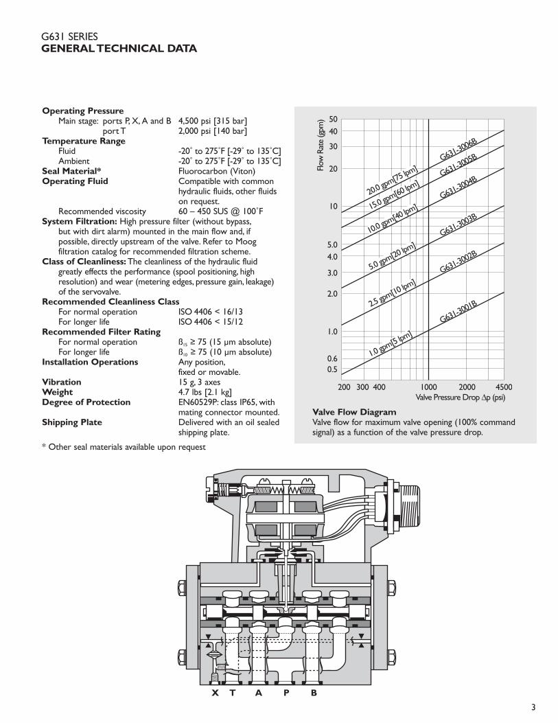
Operating PressureMain stage: ports P, X, A and B 4,500 psi [315 bar]
port T 2,000 psi [140 bar] Temperature Range
Fluid -20˚ to 275˚F [-29˚ to 135˚C]Ambient -20˚ to 275˚F [-29˚ to 135˚C]
Seal Material* Fluorocarbon (Viton)Operating Fluid Compatible with common
hydraulic fluids, other fluidson request.
Recommended viscosity 60 – 450 SUS @ 100˚FSystem Filtration: High pressure filter (without bypass,
but with dirt alarm) mounted in the main flow and, ifpossible, directly upstream of the valve. Refer to Moogfiltration catalog for recommended filtration scheme.
Class of Cleanliness: The cleanliness of the hydraulic fluid greatly effects the performance (spool positioning, highresolution) and wear (metering edges, pressure gain, leakage) of the servovalve.
Recommended Cleanliness ClassFor normal operation ISO 4406 < 16/13For longer life ISO 4406 < 15/12
Recommended Filter RatingFor normal operation ß15 ≥ 75 (15 µm absolute)For longer life ß10 ≥ 75 (10 µm absolute)
Installation Operations Any position,fixed or movable.
Vibration 15 g, 3 axesWeight 4.7 lbs [2.1 kg]Degree of Protection EN60529P: class IP65, with
mating connector mounted.Shipping Plate Delivered with an oil sealed
shipping plate.
* Other seal materials available upon request
5040
30
20
10
5.04.0
3.0
2.0
1.0
0.60.5
200 300 400 1000 2000 4500
Flow
Rat
e (g
pm)
Valve Pressure Drop ∆p (psi)
G631-300
6B
G631-300
5B
G631-300
4B
G631-300
3B
G631-300
2B
G631-300
1B
20.0 gpm
[75 lpm
]
15.0 gpm
[60 lpm
]
10.0 gpm
[40 lpm
]
5.0 gpm
[20 lpm
]
2.5 gpm
[10 lpm
]
1.0 gpm
[5 lpm]
Valve Flow DiagramValve flow for maximum valve opening (100% command signal) as a function of the valve pressure drop.
G631 SERIESGENERAL TECHNICAL DATA
X T A P B
4
1 2 3 5 7 10 20 30 50 70100
-10
-8
-6
-4
-2
0
+2
50
30
10
70
903,000 PSI DTE -24AT 100˚F (38˚C)±25%INPUT AMPLITUDE
Frequency (Hz)Frequency Response
Phas
e La
g (d
egre
es)
Am
plitu
de R
atio
(dB
)
0 10 20 30 40 50
25
50
75
100
Time (ms)Step Response
Stro
ke (
% m
ax)
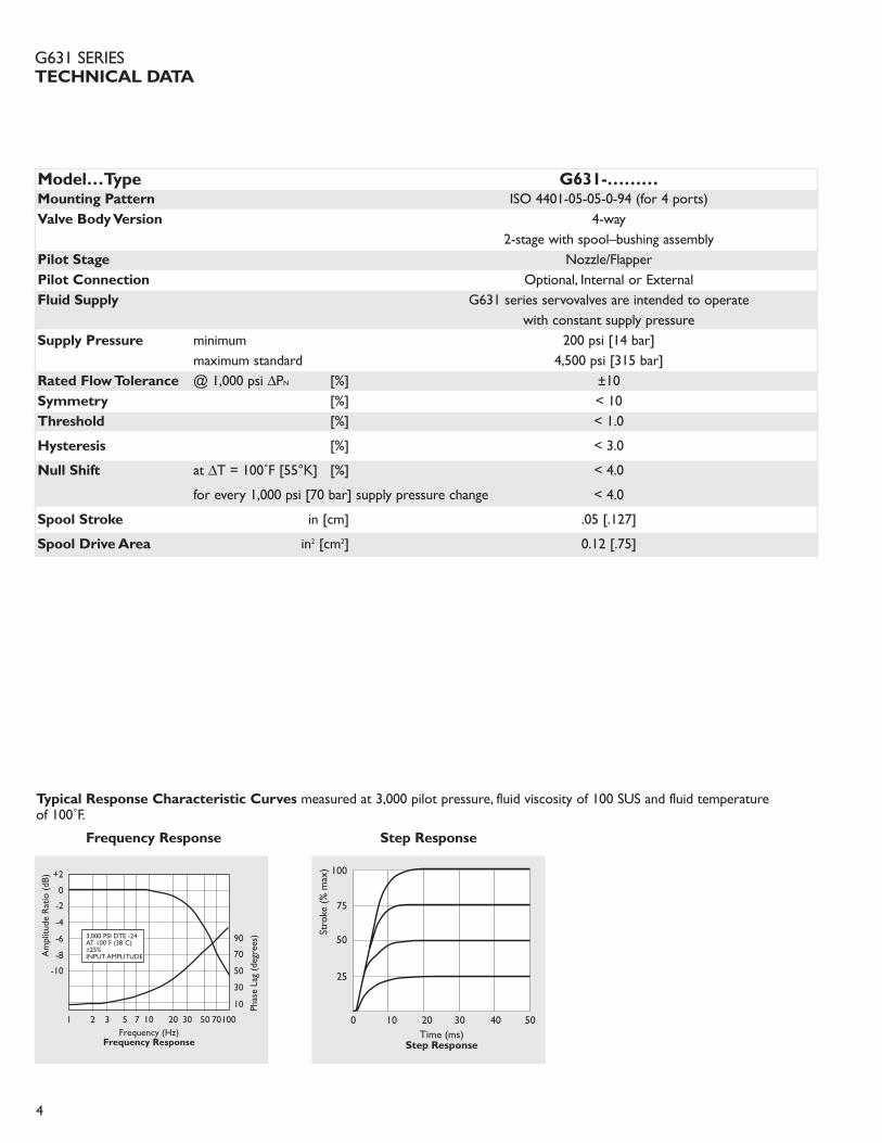
Typical Response Characteristic Curves measured at 3,000 pilot pressure, fluid viscosity of 100 SUS and fluid temperature of 100˚F.
Frequency Response Step Response
Model…Type G631-………Mounting Pattern ISO 4401-05-05-0-94 (for 4 ports)Valve Body Version 4-way
2-stage with spool–bushing assemblyPilot Stage Nozzle/FlapperPilot Connection Optional, Internal or ExternalFluid Supply G631 series servovalves are intended to operate
with constant supply pressureSupply Pressure minimum 200 psi [14 bar]
maximum standard 4,500 psi [315 bar]Rated Flow Tolerance @ 1,000 psi ∆PN [%] ±10Symmetry [%] < 10Threshold [%] < 1.0
Hysteresis [%] < 3.0
Null Shift at ∆T = 100˚F [55°K] [%] < 4.0
for every 1,000 psi [70 bar] supply pressure change < 4.0
Spool Stroke in [cm] .05 [.127]
Spool Drive Area in2 [cm2] 0.12 [.75]
G631 SERIESTECHNICAL DATA
A B
T
P
F4 F3
X
YX
F1 F2
5
.256[6.50] THRU
5.43 MAX
2.95
.011
PIN C
46.00
TO DEPTH SHOWN
PIN A
4.20
4X
ELECTRICAL
.437[11.1]2.29
3.15 MAX
.906
54.00
[118.6]
1.812
COVER SCREWNULL ADJUST
2.126
3.72
[40.1]
4.67 MAX
P PORTBore 2
PIN D
[94.5]2.76
CONNECTOR
3.84
[58.2]
[106.7]
2.60
FILTERREPLACABLE
[80.0]
1.38
[97.5]
2.29
[70.0]
[35.0]
[66.0]
[35.3]
23.00
PIN B
[137.9]
1.39
1.063
[74.9]
X PORTBore 1
27.00
1.58
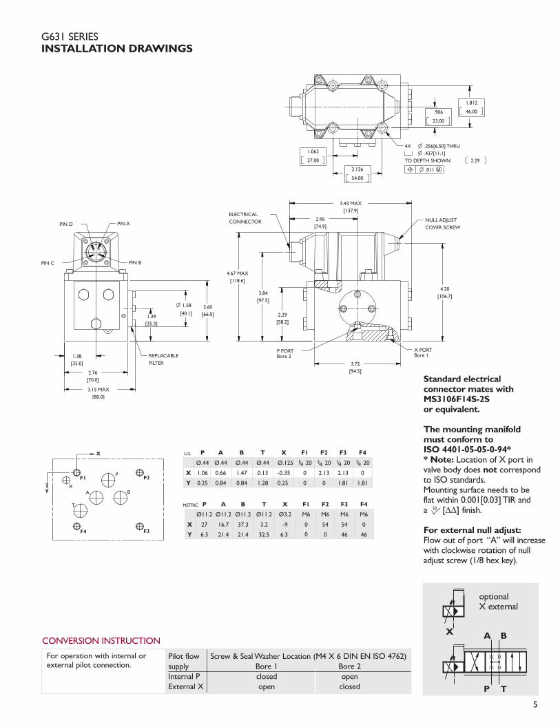
G631 SERIESINSTALLATION DRAWINGS
Pilot flow Screw & Seal Washer Location (M4 X 6 DIN EN ISO 4762)supply Bore 1 Bore 2Internal P closed openExternal X open closed
CONVERSION INSTRUCTION
For operation with internal orexternal pilot connection.
optionalX external
P A B T X F1 F2 F3 F4
Ø.44 Ø.44 Ø.44 Ø.44 Ø.125 1/4 20 1/4 20 1/4 20 1/4 20
X 1.06 0.66 1.47 0.13 -0.35 0 2.13 2.13 0
Y 0.25 0.84 0.84 1.28 0.25 0 0 1.81 1.81
P A B T X F1 F2 F3 F4
Ø11.2 Ø11.2 Ø11.2 Ø11.2 Ø3.2 M6 M6 M6 M6
X 27 16.7 37.3 3.2 -9 0 5
0
4 54 0
Y 6.3 21.4 21.4 32.5 6.3 0 46 46
U.S.
METRIC
Standard electricalconnector mates withMS3106F14S-2Sor equivalent.
The mounting manifoldmust conform toISO 4401-05-05-0-94** Note: Location of X port invalve body does not correspondto ISO standards.Mounting surface needs to beflat within 0.001[0.03] TIR anda 32 [∆∆] finish.
For external null adjust:Flow out of port “A” will increasewith clockwise rotation of nulladjust screw (1/8 hex key).
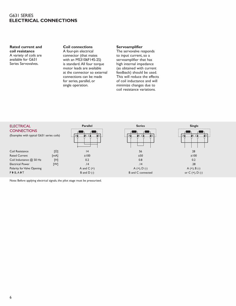
Rated current and coil resistanceA variety of coils areavailable for G631Series Servovalves.
Coil connectionsA four-pin electrical connector (that mates with an MS3106F14S-2S) is standard. All four torquemotor leads are availableat the connector so external connections can be madefor series, parallel, orsingle operation.
ServoamplifierThe servovalve respondsto input current, so a servoamplifier that hashigh internal impedance(as obtained with currentfeedback) should be used.This will reduce the effectsof coil inductance and willminimize changes due tocoil resistance variations.
6
ELECTRICALCONNECTIONS
Coil Resistance [Ω]Rated Current [mA]Coil Inductance @ 50 Hz [H]Electrical Power [W]Polarity for Valve OpeningP ç B, A ç T
Parallel
14±1000.2.14
A and C (+) B and D (-)
Series
56±500.8.14
A (+), D (-)B and C connected
Single
28±1000.2.28
A (+), B (-)or C (+), D (-)
A B C D A B C D A B C D
Note: Before applying electrical signals, the pilot stage must be pressurized.
G631 SERIESELECTRICAL CONNECTIONS
(Examples with typical G631 series coils)

7
G631 SERIESORDERING INFORMATIONSPARE PARTS AND ACCESSORIES
G631 • • • • • A
Optional FeatureSeries specification
Valve VersionH
Model Number Type Designation
Model DesignationAssigned at the factory
Factory Identification (Revision Level)
Rated Flow QN gpm [lpm]At ∆PN = 75 psi [5 bar] per land At ∆PN = 500 psi [35 bar] per land
05 0.4 [1.5] 1 [5]10 1 [3.7] 2.5 [10] 20 2 [7.5] 5 [20]40 4 [15] 10 [40]60 6 [22] 15 [60]75 8 [30] 20 [75]
Maximum Operating Pressure (P) and Body Material J 4,500 psi [315 bar] Aluminum
Spool Position without Electrical SignalM Mid-position
Bushing/Spool TypeO 4-way / axis cut / linearD 4-way / ±10% overlap / linear
Signals for 100% Spool StrokeQ ±15 mA (series)R ±50 mA (series)
Valve ConnectorB Connector over B-side
Seal MaterialV FPM (Viton)
Pilot Connections and Pressure4 Internal5 External
Pilot StageF Standard Flow, Nozzle-Flapper
Special Equipment– None
STANDARD MODELS
ModelRated Flow(∆ 1,000 psi)
gpm lpm
G631-3001A H05JOFM4VBR 1.0 5.0 < 0.52 < 2.0 100 28G631-3002A H10JOFM4VBR 2.5 10 < 0.60 < 2.3 100 28G631-3003A H20JOFM4VBR 5.0 20 < 0.70 < 2.6 100 28G631-3004A H40JOFM4VBR 10.0 40 < 0.78 < 3.0 100 28G631-3005A H60JOFM4VBR 15.0 60 < 0.86 < 3.2 100 28G631-3006A H75JOFM4VBR 20.0 75 < 0.96 < 3.6 100 28
*Overdrive more than 10% of rated current is NOT recommended.
Internal Leakage(at 3,000 psi)
gpm lpm
Rated Current(Single Coil)*
mA
Nominal CoilResistance
OhmsType Designation
Moog Part Size Moog Part NumberO-Rings (included in delivery), FPM 85 Shore
for P,T,A and B ID 0.472 x 0.079 G2141-012-020for X ID 0.315 x 0.079 G2141-008-020
Mating Connector (not included in delivery) P/N 49054F014S002S(MS3106F14S-2S)Flushing Block P/N B67728-002Mounting Bolts (not included in delivery)
1/4 - 20 NC x 2-3/4 long (4 pieces) P/N A31324-144B[M6 x 1.0 x 70 mm] [B64929-7B70]
Replaceable Filter P/N A67999-100Filter Replacement Kit (includes service manual) P/N B52555RK200K001
SPARE PARTS AND ACCESSORIES
H • • • • F M • V B • –

WHAT MOVES YOUR WORLD
TAKE A CLOSER LOOK
www.moog.com/industrial©2007 Moog, Inc.
All trademarks as indicated herein are the property of Moog, Inc.and its subsidiaries. All rights reserved.
G631 CDL6641 RevK 500-339 1008TJW/PDF
Solutions for flow control of high performance applications are available around the world. For more information,visit our Web site or contact one of the locations below.
Argentina+54 11 4326 [email protected]
Australia+61 3 9561 [email protected]
Austria+43 664 144 65 [email protected]
Brazil+55 11 5523 [email protected]
China+86 21 5854 [email protected]
Finland+358 9 2517 [email protected]
France+33 1 4560 [email protected]
Germany+49 7031 [email protected]
Hong Kong+852 2 635 [email protected]
India+91 80 4120 [email protected]
Ireland+353 21 451 [email protected]
Italy+39 0332 421 [email protected]
Japan+81 436 55 [email protected]
Korea+82 31 764 [email protected]
Luxembourg+352 40 46 [email protected]
Netherlands+31 252 462 [email protected]
Norway+47 224 [email protected]
Russia+7 [email protected]
Singapore+65 677 [email protected]
South Africa+27 11 655 [email protected]
Spain+34 902 133 [email protected]
Sweden+46 31 680 [email protected]
Switzerland+41 71 394 [email protected]
United Kingdom+44 1564 784 [email protected]
USA+1 716 652 [email protected]