G3/bl 031 541 AN IMPLEMENTATION AND ANALYSIS OF … · Sciences and Humanities, ... The development...
108
(NASA-CR-]_7409) AN IHPLEHENTAT[_N ANO ANAL¥S[S OF THE AgSTRACT SYNTAX NPTAT[ON ONE AN0 THE BASIC ENCODING RULES (_igital Techn°l°gy) _ P CSCL 09B h_ .j--o .x ! /j,.; dd 2 /_ 6 L/ 7 N91-13105 Unclas G3/bl 031_541 AN IMPLEMENTATION AND ANALYSIS OF THE ABSTRACT SYNTAX NOTATION ONE AND THE BASIC ENCODING RULES James D. Harvey Alfred C. Weaver Digital Technology August 1990 Cooperatlve Agreement NCCg- 16 Research Acvtlvlty No. SE.31 NASA Johnson Space Center Engineering Directorate Avionic Systems Division © © Research Institute for Computing and Information Systems University of Houston - Clear Lake II II I __ T.E.C.H.N.I.C.A.L R.E.P.O.R.T https://ntrs.nasa.gov/search.jsp?R=19910003792 2018-05-28T04:23:05+00:00Z
-
Upload
truonglien -
Category
Documents
-
view
216 -
download
2
Transcript of G3/bl 031 541 AN IMPLEMENTATION AND ANALYSIS OF … · Sciences and Humanities, ... The development...

(NASA-CR-]_7409) AN IHPLEHENTAT[_N ANOANAL¥S[S OF THE AgSTRACT SYNTAX NPTAT[ON ONEAN0 THE BASIC ENCODING RULES (_igitalTechn°l°gy) _ P CSCL 09B
h_
.j--o .x ! /j,.; dd
2 /_ 6 L/ 7N91-13105
UnclasG3/bl 031_541
AN IMPLEMENTATION AND ANALYSIS OF
THE ABSTRACT SYNTAX NOTATION ONE
AND THE BASIC ENCODING RULES
James D. HarveyAlfred C. Weaver
Digital Technology
August 1990
Cooperatlve Agreement NCCg- 16Research Acvtlvlty No. SE.31
NASA Johnson Space CenterEngineering Directorate
Avionic Systems Division
© ©
Research Institute for Computing and Information Systems
University of Houston - Clear Lake
II II I __
T.E.C.H.N.I.C.A.L R.E.P.O.R.T
https://ntrs.nasa.gov/search.jsp?R=19910003792 2018-05-28T04:23:05+00:00Z

;,7=z7 ......
The
RICIS
Concept
I
i
i
u
m
i
J
id
i
miThe University of Houston-Clear Lake established the Research Institute for
Computing and Information systems in 1986 to encourage NASA Johnson SpaceCenter and local industry to actively support research in the computing and
information sciences. As part of this endeavor, UH-Clear Lake proposed a ..ipartnership with JSC to jointly define and manage an integrated program of research
in advanced data processing technology needed for JSC's main missions, including .....
administrative, engineering and science responsibilities. JS C agreed and entered into <-=_
a three-year cooperative agreement with UH-Clear Lake beginning in May, 1986, tojointly plan and execute such research through RICIS. Additionally, under
Cooperative Agreement NCC 9-16, computing and educational facilities are sharedby the two institutions to conduct the research.
The mission of RICIS is to conduct, coordinate and disseminate research on :_ -
computing and information systems among researchers, sponsors and users fromUH-Clear Lake, NASA/JSC, and other research organizations. Within UH-Clear
Lake, the mission is being implemented through interdisciplinary involvement of
faculty and students from each of the four schools: Business, Education, HumanSciences and Humanities, and Natural and Applied Sciences.
Other research organizations are involved via the "gateway" concept. UH-Clear
Lake establishes relationships x_ith other universities and research o_rga_nizatigns _ _having common research interests, to provide additional sources of expertise toconduct needed research.
A major role of RICIS is to find the best match of sponsors, researchers and
research objectives to advance knowledge in the computing and information _sciences. Working jointly with NASA/JSC, RICIS advises on research needs,recommends principals for conducting the research, provides technical and
administrative support to coordinate the research, and integrates technical results
!nto the cooperative goals of UH-Clear Lake and NASA/JSC.
I

AN IMPLEMENTATION AND ANALYSIS OF
THE ABSTRACT SYNTAX NOTATIONONE
AND THE BASIC ENCODING RULES

I
Um
!1
UO
B
z
W
i
ugm
m
U
m
IB
U
m
U
zu
mm
i
RD
I
!i

Preface
This research was conducted under the auspices of the Research Institute for
Computing and Information Systems by James D. Harvey and Alfred C. Weaver by
Digital Technology. Dr. George Collins, Associate Professor of Computer Systems
Design, served as RICIS technical representative for this activity.
Funding has been provided by Avionics Systems Division, NASA/JSC through
Cooperative Agreement NCC 9-16 between NASA Johnson Space Center and the
University of Houston-Clear Lake. The NASA technical monitor for this activity was
Frank W. Miller,
The views and conclusions contained in this report are those of the author and
should not be interpreted as representative of the official policies, either express or
implied, of NASA or the United States Government.
v
w
i
w

him
um
mmu
iI
g
IB
J
lw
I
IE
gl
ID
I
mI
W
mm

An Implementation and Analysis of
the Abstract Syntax Notation One
and the Basic Encoding Rules
James D. HarveyAlfred C. Weaver
w
This work was supported by NASA Johnson Space Center through the Research Institute
for Computer and Information Science at the University of Houston Clear Lake, contract SE.31,subtask 056.

II
J
I
m
z
u
u
11
m
II
ul
w
L
II
g
mm
J
1mr
w
u
ABSTRACT
The development of computer science has produced a vast number of machine architectures,
programming languages, and compiler technologies. The cross product of these three
characteristics defines the spectrum of previous and present data representation methodologies.
With regard to computer networks, the uniqueness of these methodologies presents an obstacle
when disparate host environments are to be interconnected. Interoperability within a
heterogeneous network relies upon the establishment of some sort of data representation
commonality.
The International Standards Organization (ISO) is currently developing the Abstract Syntax
Notation One standard (ASN.I) and the Basic Encoding Rules standard (BER) that collectively
address this problem. When used within the Presentation Layer of the Open Systems
Interconnection Reference Model, ASN. 1 and BER provide the data representation commonality
required to facilitate interoperability. This thesis presents the details of ASN.I and BER and
describes a compiler that was built to automate their use. Experiences with this compiler are also
discussed which provide a quantitative analysis of the performance costs associated with the
application of these standards. Ultimately, an evaluation is offered as to how well suited ASN. 1
and BER are in solving the common data representation problem.

m
iii
il
i
J
II
m
mIll
W
ii
ul
mU
miii
w
III
W
iii

CONTENTS
!
1. Network Heterogeneity .................... 1I. 1 Architectural Issues ................... 1
1.2 Languages and Compilers ................. 4
1.3 Solving the Problem ................... 5
2. The OSI Model ...................... 7
2.1 Layered Protocols .................... 72.2 The ISO Stack ..................... 9
2.3 The Presentation Layer .................. 13
3. An ASN.1 and BER Tutorial .................. 163.1 Overview ...................... 16
3.2 The Abstract Syntax Notation One (ASN.1) ............ 20
3.3 Basic Encoding Rules (BER) ................ 41
3.4 Pending ModificalJons .................. 54
4. The ASN. 1 Compiler .............. . ...... 62
4.1 Physical Specifications .................. 624.2 Generating Declarations .................. 63
4.3 Generating Code .................. 65
4.4 The Run-Time Library .................. 674.5 Performance ..................... 69
5. Observations ....................... 71
5.1 Ambiguity ...................... 71• 735.2 Library Management . . . . ..............
5.3 Efficiency versus Generality ................. 76
5.4 Explicit Tagging .................... 775.5 Sets • . ....... 785.6 Macros ....................... 79
6. Conclusions ....................... 81
6.1 Clarity ....................... 81
6.2 Ease of Implementation .................. 82
6.3 Efficiency ...................... 836.4 Contributions ..................... 84
6.5 An Overall Assessment .......... . ....... 86
APPENDIX A ....................... 87
APPENDIX B ..................... • • 91
REFERENCES ....................... 94
-i-
u
LIST OF FIGURES
Figure 5.
Figure 6.
Figum 7.
Figure 8.
Figure 9.
Figure 10.
Figure I 1.
Figure 12.
Figure 13.
Figure 14.
Figure 15.
Figure 16.
Figure 17.
Figure 18.
Figure 19.
Figure 20.
Figure 21.
Figure 22.
Figure 23.
Figure 24.
Figure 25.
Hgure 26.
Figure 27.
Figure 28.
Figure 29.
Two's Complement Representation of Negative Two ........Figure 1.
Figure 2. IEEE Floa_g point Format
Figure 3. IEEE Representation of 16.5 ...............
Figure 4. iBM Floating Point Format .......... . . ....
The IBM Interpretation .................
A Network Stack
The ISO Stack ........
Encoding Format ...................
Using an ASN. 1 Compiler ................
ASN. 1 definition of WIMP ................
Request (without named types) ...............
A new definition of WIMP ................
A more complex value assignment ..............
A more robust WIMP .................
Useful Definition of UTC'l'ime ...............
Syntactic forms of UTCTime ...............
Object Identifier Tree ..................
Object Identifier Value for FTAM ..............
• ) • • • • • • w • • • • • •
• • • ) • • • • • • • • • • •
• • • • • • • • • w • • w
• # • • • • g • •
EXTERNAL type definition
Using a BIT STRING . .
Using the NULL Type . .
Using the SELECTION Type
Bit and Octet Numbering .
Identifier Octet (low tag number) .
Identifier Octet (extended tag number)
Length Octet Forms: short, long and indefinite
An encoding of the integer value Zero . . .
An encoding of the integer value Negative One
An encoding of a sequence value ....
2
2
3
4
4
9
10
17
20
21
24
25
27
29
30
31
34
34
35
37
38
39
42
44
45
47
49
49
50
W
mU
i
=_
g
i
m
J
W
lap
U
mid
7
I
- ii - t

w
w
Figure
Figure
Figure
Figure
Figure
Figure
Figure
Figure
Figure
Figure
Figure
Figure
Figure
Figure
Figure
Figure
30. Encoding a result value ................. 52
31. Adding the IMPLICIT keyword .............. 53
32. A New Encoding of Result ................ 54
33. A Module with the IMPLICIT Tag Default ........... 55
34. An Enumerated Type .................. 56
35. An External Type Reference ............... 56
36. Using EXPORT and IMPORT ............... 57
37. Example of a REAL type assignment ............. 58
38. Example of a REAL Value assignment ............ 58
39. Using Subtypes ................... 59
40. A Macro Definition .................. 60
41. Using a Macro Definition ................ 61
42. Declarations of WIMP APDU's .............. 64
43. The Encoding and Decoding Functions ............ 65
44. The Decoding Finite State Machine ............. 67
45. Mutually Dependent Modules ............... 74
o,.
- III -

n
TABLE I. ASN. 1 Universal Types
LIST OF TABLES
• • • • • • • • • • • • • • . • • 43
lw
W
w
D
m
J
ID
i
mill
I
- iV °

I. Network Heterogeneity
The development of computer science has produced a vast number of disparate machine
architectures, programming languages, and compiler technologies. The cross product of these
three characteristics def'mes the spectrum of previous and present data representation
methodologies. Although at one time the uniqueness of each technique provided vendors with a
convenient and desirable means to monopolize their customers, the proliferation of computers
and the realization of the benefits inherent to distributed processing have now obscured any of the
previous advantages associated with incompatible data representations. Nevertheless, established
manufacturers are unwiUing to abandon their investment in their own unique data representation
schemes. Thus when computer networks interconnect these heterogeneous environments, a
solution to the problem of data transfer across incompatible host environments must be provided.
I.I Architectural Issues
As a simple illustration of how hardware architecture influences this problem, consider three
different techniques used to represent integer values: sign magnitude, diminished radix
complement (one's complement), and radix complement (two's complement). Although most
contemporary architectures now use two's complement, there are some architectures still in use
that do not. t Consequently, if integer data were to be exchanged between a one's complement
1. The CDC 6600 is a one's oomple_nent_chitectme.
w
2
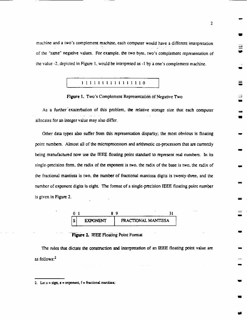
machine and a two's complement machine, each computer would have a different interpretation
of the "same" negative values. For example, the two byte, two's complement representation of
the value -2, depicted in Figure 1, would be interpreted as -1 by a one's complement machine.
IB
11
I 1111111111111110
Figure 1. Two's Complement RepresentatiOn Of Negative Two
As a further'exacerbation of this problem, the relative storage size that each computer
allocates for an integer value may also differ.
E
J
mg
Other data types also suffer from this representation disparity; the most obvious is floating
point numbers. Almost all of the microprocessors and arithmetic co-processors that are currently
being manufactured now use the IEEE floating point standard to represent real numbers. In its
singIe-precision form, the radix of the exponent is two, the radix of the base is two, the radix of
the fractional mantissa is two, the number of fractional mantissa digits is twenty-three, and the
number of exponent digits is eight. _e format of a single-precision IEEE floating point number
is given in Figure 2.
W
u
I
01 89 31
S_ EXI'ONEN'r [ FRACTIONAL MANtiSSA
Figure 2,. IEEE Floating Point Format
g
w
The rules that dictate the construction and interpretation of an IEEE floating point value are
as follows: 2
mI
m
2. Let s --sign. • z exponent, f= fractionalmantissa:m1ira
l
im
-- 3
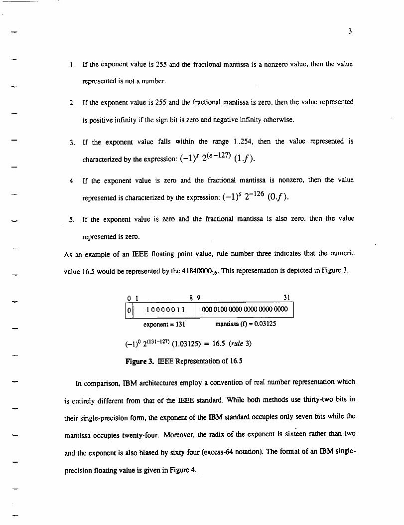
1. If the exponent value is 255 and the fractional mantissa is a nonzero value, then the value
represented is not a number.
2. If the exponent value is 255 and the fractional mantissa is zero, then the value represented
is positive infinity if the sign bit is zero and negative infinity otherwise.
3. If the exponent value falls within the range 1..254, then the value represented is
characterized by the expression: (--1) s 2 (e-127) (1 .f).
4. If the exponent value is zero and the fractional mantissa is nonzero, then the value
represented is characterized by the expression: (-1) s 2 -126 (O.f).
5. If the exponent value is zero and the fractional mantissa is also zero, then the value
represented is zero.
As an example of an IEEE floating point value, rule number three indicates that the numeric
value 16.5 would be represented by the 4184000016. This representation is depicted in Figure 3.
0 1 89 31
0 10000011 00001000000000000000000 ]
exponent = 131 mantissa(f)= 0.03125
(-1) ° 2 (13t-127) (1.03125) -- 16.5 (rule 3)
Figure 3. IEEE Representation of 16.5
In comparison, IBM architectures employ a convention of real number representation which
is entirely different from that of the IEEE standard. While both methods use thirty-two bits in
their single-precision form, the exponent of the IBM standard occupies only seven bits while the
mantissa occupies twenty-four. Moreover, the radix of the exponent is sixteen rather than two
and the exponent is also biased by sixty-four (excess-64 notation). The format of an IBM single-
precision floating value is given in Figure 4.

u
4
III
0 1 78 31
IS] EXPONENT FRACTIONAL MANTISSA I
Figure 4. IBM Floating Point Format
The obvious consequence of these differences in floating point representations is the inability
for one machine to correcdy interpret the data representation of the other. If a machine that uses
the IEEE standard were to send its sin#e-precision rep_sentation Of the value 16.5 (i.e.
41840000t6) to an IBM mainframe, the IBM computer would interpret this value as 8.25 rather
than 16.5. This is illustrated in Figure 5.
3101 78
1ol,ooooo, Iexponent = 65 mantissa = 0.51562.5
(-1) ° 16(65-64) (0.515625) = 8.25
Figure 5. The IBM Interpretation
To complicate the architectural issues even further, characteristics such as word alignment,
byte ordering, and addre.ssability may also present problems. Moreover, the influence of
hardware architecture extends beyond just that of the CPU. This is evident when one considers
the difference between the ASCII and EBCDIC character sets. Certainly the architecture of
peripherals also bears significance. The interaction and interdependencies that exist between all
of these characteristics suggest that the influence of hardware architecture on the problem of
disparate data representations is complex.
11o
W
J
Ill
g
qD
=_
i
w
i
J
i
IBm
1.2 Languages and Compilers
The differences in conditional expression evaluation that occur within the C and Ada
programminglanguagesdemonstratethemannerinwhichprogramminglanguagescancontributel
llm

5
to this problem. In all C implementations a conditional expression is true if it evaluates to any
non-zero value; it is consequently false if it evaluates to zero precisely. Although the C
programming language does not explicitly provide a boolean type, most C programmers use an
integer data type to represent these kinds of values. In Ada, however, a boolean type is
predefined as an enumerated type in package STANDARD. By virtue of its enumerated form,
the only requirement relating to the representation of its values is that the representation of false
be numerically less than the representation of true. Thus, each individual Ada compiler
determines the exact nature of how boolean values are represented. Since Ada treats conditional
expressions as boolean values, the evaluation of such expressions may clearly vary. In this
respect, if the same application program were to be implemented in two different programming
languages, it is feasible for two values that are intended to represent the "same" condition to be
different. In fact, it is more precise to attribute this phenomenon to the differences between
compiler implementations than to the difference between programming language definitions. 3
Consequently, applications written in the "same" programming language may experience
miscommunication.
v
1.3 Solving the Problem
With regard to network heterogeneity, the disparate data representation problem is clear.
Since different host environments possess different methods of representing data, the
interoperability of these machines can not be achieved solely by the establishment of a reliable
connection. At some point during the communication, a transformation to and from each host
3. MicroSoft C compilers lxett charactervalues as signed quantities by default. Consequently, all charactervalues aresign extended during type conversions. Lattice C compilers, however, consider all charactervalues to be unsignedby default anddo not sign extend.

machine'snativerepresentationmustbeperformed.This functioncould be carried out in one of
two ways: either (1) each host environment must be cognizant-of the representation
characteristics of each other host environment with which it wishes to communicate, and
therefore each host must perform a potentially different transformation for every host-to-host
combination, or (2) a common method of data representation must be established whereupon each
host would be responsible for the single transformation between this standard method and its own
native representation. This latter approach, which is certainly the more desirable alternative,
captures the intent of the Abstract Syntax Notation One and the associated Basic Encoding Rules.
I
g
u
U
I
J
U
g
w
J
m
m
i
u
W
J
m

-- 7
w
2. The OSI Model
As a solution to the problem of disparate data representations, the Intemational Organization
for Standardization (ISO) has developed the Abstract Syntax Notation One standard ill (ISO
8824) and the Basic Encoding Rules standard [21 (ISO 8825). Defined in the context of network
communications, the purpose of these two standards is to provide the data representation
commonality required to interconnect disparate host environments. To understand how Abstract
Syntax Notation One (ASN.1) and the Basic Encoding Rules (BER) provide a solution to this
problem, it is necessary that one first understand the Open Systems Interconnection (OSI) model,
the environment in which these two standards operate.
2.1 Layered Protocols
The design and implementation of a network is an inherently complex task. There are a wide
range of problems to be solved which collectively demand expertise in many different theoretical
disciplines. To offer structure to this process and thereby minimize its complexity, most
networks are organized as a series of layers where each layer encapsulates a particular aspect of
the problem. The relationship between these layers is hierarchical. Each layer is dependent upon
the services provided by the layer directly beneath it and is, by the same token, responsible for
providing a set of services to the layer directly above it. The number of layers, the names of each
layer, and the functionality provided by each layer may differ from one network design to
another. However, the overall objective of simplifying the problem through a hierarchy of

n
8
abstractions is universal.
Since each layer of a network implementation is responsible for providing a set of services to
the layer directly above it, the exact nature of these services is reflected by the interface that
exists between them. The most important requirement of this relationship is that the
implementation details of how any given layer provides its services should be transparent to the.... v _ .....
layer that uses it. Hence, each layer has a different perspective of the communications problem to
be solved. Put another way, each layer creates an abstraction of communication capabilities to
the layers above it. These capabilities increase in sophistication as one proceeds up the stack.
m
g
m
W
U
During an instance of communication, each layer within an implementation carries on a
conversation with the corresponding layer of another implementation. A well defined set of rules
and conventions, known as a protocol, govern the manner in which each conversation is carried
out. These pairs of communicating layers are often called peers or peer protocols. The
hierarchical structure of these protocols gives rise to the term layered protocols or protocol
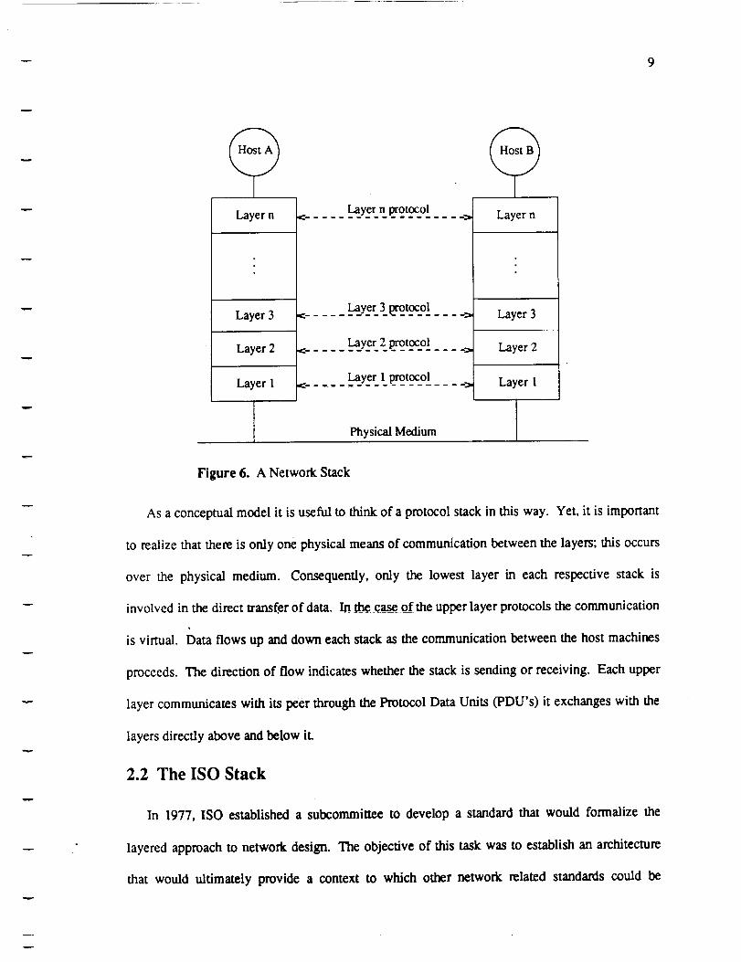
stack. This arrangement is illustrated in Figure 6 below.
J
I
im
u
w
J
w
i
9
Layer n protocolLayer n _:................... =, Layer n
Layer 3
Layer 2
Layer 3 protocol
Layer 2 protocol
Layer 1 protocol
Layer 3
Layer 2
Layer 1 Layer 1
, Physical Medium I
Figure 6. A Network Stack
As a conceptual model it is useful to think of a protocol stack in this way. Yet, it is important
to realize that there is only one physical means of communication between the layers; this occurs
over the physical medium. Consequently, only the lowest layer in each respective stack is
involved in the direct transfer of data. In the case of the upper layer protocols the communication
is virtual. Data flows up and down each stack as the communication between the host machines
proceeds. The direction of flow indicates whether the stack is sending or receiving. Each upper
layer communicates with its peer through the Protocol Data Units (PDU's) it exchanges with the
layers directly above and below it.
2.2 The ISO Stack
In 1977, ISO established a subcommittee to develop a standard that would formalize the
layered approach to network design. The objective of this task was to establish an architecture
that would ultimately provide a context to which other network related standards could be
w

10
applied. The result was the creation of a new standard (ISO 7498) which defined the Open
Systems Interconnection (OSI) reference model. The framework that OSI represents enables the
consistency of all relevant communications standards to be maintained. The OSI reference model
is commonly referred to as the ISO stack.
The seven layers of the ISO stack are depicted in Figure 7.
Application
Presentation
Session
Transport
Network
Data Link
Physical
Application protocol _Presentationprotocol
c.... .Sc__ionpmt_col_ ___:_
Transport protocol
_ Ne_o_r_kp_[_)col
DataLink protocol
Physical protocol
Application
Presentation
Session
Transport
Network
Dam Link
Physical
I
_I
u
a
m_1
w
I
g
Physical Medium
m
Figure 7. The ISO Stackg
The functionality of each one Of the seven ISO layers is as follows: lib
° Physical Layer: It is the responsibility of the Physical Layer to facilitate the transmission
of raw bits over a communication medium. As such, the Physical Layer provides the
interface between the binary values and the physical signaling. Typical design issues
relevant to the Physical Layer are:
a. how the data is to be physically represented (i.e., voltage levels, lightwave
characteristics, etc),
J
u
w
U
w

-- 11
w
b. the speed and capacity of transmissions,
c. whether or not transmissions may proceed simultaneously in both directions,
d. and how a physical connection to the medium is made.
2. Data Link Layer: It is the responsibility of the Data Link Layer to take the raw
transmission capability offered by the Physical Layer and make it reliable. To do this the
Data Link Layer breaks up the transfer data into frames. Through the use of various error
detection algorithms, this framing structure enables the Data Link Layer to detect
transmission errors. By far, the most pervasive technique used to detect these errors is the
cyclic redundancy code (CRC).
ISO defines two types of data link services, connection mode and connectionless mode.
In the connection mode, the data link service facilitates the establishment of a logical
connection, the negotiation of quality of service, the reliable transfer of data, and an
expedited data service. In contrast, the connectiordess mode provides all of the above
services except the establishment of a logical connection. The ramifications of not
establishing this logical connection are that the data link service may discard data units,
duplicate data units, and deliver data units in an order which differs from that in which they
were originally presented by the user.
3. Network Layer: The Network Layer provides a means of transferring data in a manner
which is independent of the underlying network architecture. This responsibility dictates
that the Network Layer offer the capability of transferring data across any sort of network
or even a network of networks. To do this, the Network Layer performs the muting and
relaying of data, establishes network connections to support this routing, facilitates error
recovery by utilizing the error notification provided by the Data Link Layer, packetizes the
data to be transferred and sequences the delivery of these data units. It is also the
I
12
responsibility of the Network Layer to implement congestion control within the network,
and to detect and discard outdated, nomadic packets (i.e., lifetime control).
ii
U
4. Transport Layer: The Transport Layer adds reliability to the otherwise unreliable
datagram service provided by the network and datalink layers below it. The transport user
(usually the Session Layer) submits arbitrarily large messages (Transport Service Data
Units or TSDUs) to Transport for transmission. The TSDUs are segmented into smaller
messages (Transport Protocol Data Units or TPDUs) whose size is appropriate for the
underlying layers. A checks_ is calculated for each message segment and a unique
sequence number is assigned to each segment. A rewansmission timer is started when the
Transport Layer delivers the segment to the underlying Network Layer for transmission.
The receiving Transport Layer acknowledges each segment with a special "ack" message.
If the transmitter's Transport Layer fails to receive an acknowledgement for a segment by
the time its retransmission timer expires, the Transport Layer stops the transmission stream
and retransmits all messages beginning with the one whose acknowledgement is missing.
In this way the Transport Layer creates a connection-oriented service (a "virtual circuit").
Messages are guaranteed to arrive at the receiver in order, without loss or duplication.
I
u
I
m
I
I
mn
U
I
5. Session Layer: The Session Layer provides the user's interface to the Transport service. It
manages the dialogue between two communicating Presentation Layer processes so that
their exchange of data is organized and synchronized. This management involves
providing an interface to enable specific options of the session connection to be negotiated.
Moreover, in the context of managing a dialogue between the user and a machine or device,
the Session Layer ensures that proper access rights are being observed.
6. Presentation Layer: The Presentation Layer is primarily concerned with the specific
method in which data is represented. This focus touches upon issues such as text
I
l
1Ira
i
W

w
13
w
m
compression/expansion, encryption/decryption, and the commonality of data
representations. Within a heterogeneous network, the connected host machines may not
share the same methodology of representing semantically equivalent data. Under these
circumstances, communication is not possible unless a common methodology can be
established. The Presentation Layer provides a means of negotiation that enables this
establishment to be made, and subsequently transforms incompatible data representations
into an agreed upon methodology. Hence, the Presentation Layer provides for the
interoperability of heterogeneous networks and abstracts the issues of data representation
from the Application Layer.
7. Application Layer: The Application Layer encapsulates the semantics of the data being
exchanged. To the user, the Application Layer represents the means through which the
OSI environment can be accessed. In this respect, the Application Layer provides
functions and services that are generally useful in the support of distributed applications.
File transfer and electronic mail services exemplify the kinds of protocols found within this
layer.
Use of the Basic Encoding Rules relates exclusively to the Presentation Layer while the use
of ASN.1 pertains to both the Application Layer and the Presentation Layer. However, with
respect to the issue of evaluating ASN.I's ability to solve the disparate data representation
problem, the relationship between ASN. 1 and the Application Layer is unrevealing. Thus, it is
the Presentation Layer that largely determines the manner in which ASN. 1 and BER are used.
2.3 The Presentation Layer
As user data passes through the Presentation Layer its complexion changes significantly. To
the layers beneath the Presentation Layer, the user data parameters of a service primitive appear
as a mere sequence of octets. 4 These octets are uninterpreted by the lower layer protocol entities

14
that processthem. In theApplication Layer, the user data parameters typically correspond to
complex data types that possess significant meaning to the application protocol standards that use
them. The application entities must process the content of these values in detail in order to
provide a requested service. Therefore, the nature of this change in the user data can be viewed
as a bridge between the gap that separates syntax from semantics, it is the job of the Presentation
Layer to facilitate this transition.
Two objectives of this task make it a difficult one. First, the Presentation Layer should
provide this service in such a way that it does not overly determine the manner in which the data
is represented in the Application Layer. Second, the manner in which the information content of
a user data parameter is expressed should in no way determine the syntax of the octets. This
decoupling of semantics and syntax represents the grass roots of the ASN, 1 and BER solution.
To understand how ASN. 1 and BER achieve this decoupling, certain Presentation Layer concepts
must be understood. These concepts are the focus of the following subsections.
2.3.1 Abstract Syntax
ASN. 1 is a notation that formalizes the data types and data values of a protocol for purpose of
standardization. Specifically, ASN.1 describes the informational content of both the user data
parameters and control information that cross the interface between the Presentation Layer and
the Application Layer. The most important characteristic of how ASN. 1 presents this description
is that it does so without influencing the representation of this data on either side of this interface.
An instance of an ASN.1 description is called an abstract syntax.
J
w
J
Iil
J
m
J
m
i
l
I
g
m
w
U
U
4. The term octet is essentidly a synonym for byte given that a byte dways comtsts of eightbits.g
M

-- 15
2.3.2 Transfer Syntax
The data items that are passed from the Application Layer to the Presentation Layer will
eventually become user data parameters of the Presentation protocol that will in turn cross the
interface between the Session Layer and the Presentation Layer. However, before they cross this
interface, these data items must be transformed into an uninterpreted sequence of octets. This
transformation, or encoding, of the data values of an abstract syntax into a sequence of octets is
called a transfer syntax. The necessary properties of any transfer syntax are that it carry the
information described by the corresponding abstract syntax in a manner which is independent of
the representation of data in any particular application entity, and that the reciprocal
transformation, or decoding, of the transfer syntax into the data values of an abstract syntax be
readily applicable.
2.3.3 Presentation Context
Over any given presentation connection, the Presentation Layer must associate each abstract
syntax with a supporting transfer syntax. This enables the Presentation Layer to perform the
translation between the user data parameters of the application protocols and the octet sequences.
From within the Presentation Layer, each association forms a presentation context. To the user
of the presentation service, namely an application entity, a presentation context identifies all of
the abstract syntaxes that may be sent or received over a presentation connection. During the
lifetime of a presentation connection, the Presentation Layer may be supporting more than one
presentation context. All of the presentation contexts that have been negotiated for a given
connection are referred to as the defined context set.

mg
16
lip
I
3. An ASN.I and BER Tutorial J
The most effective means of presenting the details of both ASN. 1 and BER is to first provide
a context through which these details may be better appreciated. To establish this context a
hypothetical set of communication requirements relating to the NASA Space Station will be
examined. An application protocol will subsequently be developed using ASN.I. As the
hypothetical requirements are iteratively refined, the ASN.1 def'mition will increase in
sophistication. After the finer details of ASN. 1 are explored, the Basic Encoding Rules wiLl be
applied to typical data values of the newly created application protocol. However, before this
protocol development commences, an overview of both standards is necessary.
3.1 Overview
The ASN.1 standard defines a language used to describe data values and data types. It is
typically used by Application Layer protocols to define the types of their Application Protocol
Data Units (APDUs). For example, protocols such as File Transfer, Access, and Management
0:TAM) and Virtual Terminal (V'D use ASN. 1. However, it is important to note that the use of
ASN. 1 is not necessarily restricted to the Application Layer. Theoretically, it could be used to
define the Protocol Data Units (PDUs) of any layer.
In the ISO nomenclature, ASN.I provides the means to define an abstract syntax. To
understand this concept, it is useful to consider the term literally. In the formal academic sense, a
syntax def'mes the legal sentential forms of a language. Within the context of communications,
M
g
l
i
I
I
W
m
g
J
J
W

-- 17
one usually thinks of a syntax as defining the bit patterns used to represent data flowing across a
medium. An abstract syntax, therefore, does not define these bit patterns, but rather it
establishes a framework whereupon these bit patterns, called a transfer syntax, can be created.
The manner in which they are created depends upon the encoding rules that are applied.
The Basic Encoding Rules standard defines a specific technique for encoding data. To use
our previous ISO terminology, it defines a mapping from the abstract syntax, defined by ASN. 1,
into the transfer syntax. A BER encoding is represented as a sequence of octets. These octets
are partitioned into 3-tuples, indicated in Figure 8:
IDENTIFIER LENGTH CONTENTS
Figure 8. Encoding Format
The identifier octet(s) contain information regarding the type" and form of the encoded data
value. A primitive form indicates that the contents octets contain a direct representation of
the data value. A constructed form indicates that the contents octets contain mother embedded
encoding. The length octet(s) determine the end of an encoding. They indicate how many
contents octets represent the encoded data, or, if that this number is unknown, then they indicate
that the contents octets are delimited by a reserved bit pattern called an end of contents (EOC)
sequence. The contents octets contain a direct representation of the data value or another nested
identifier-length-contents sequence.
As an analogy, if ASN.1 is viewed as the floor plan of a house, then the BER corresponds to
the architect, and the Presentation Layer is the builder. The actual house represents the transfer
syntax. Note that a floor plan indicates the generic structure of a house: the number of rooms, the
identity of each room, and their positional relationships. This coincides with the kind of

18
information that ASN. 1 provides about a data type. Consider that there are many different ways
to build a house according to a given floor plan. Which way is chosen depends upon who the
architect is and how this architect chooses to realize the floor plan. This choice is reflected in the
set of blueprints generated. Likewise, we should not consider the BER to be the only means of
defining a transfer syntax. Yet, at the present time, the BER represent the only architect
officially in business.
Notice that if the floor plan of the house were to be changed, a new set of blueprints must be
generated in order to rebuild the house. This reveals an important characteristic of ASN. 1. When
an Application Layer protocol is described using ASN. 1, the Presentation Layer must be provided
with the encoding/decoding knowledge requitvxl to support these defined data types. In other
words, the house-builder must be given a new set of blueprints. If the ASN. 1 description of this
protocol is changed, new encoding/decoding information must be created. This is when the
automated generation of blueprints (i.e., an ASN. 1 compiler) becomes highly desirable.
Before describing what an ASN.1 compiler is, a word of caution is necessary. When it is said
that ASN. 1 provides a mechanism to define data values as well as data types, this statement has a
tendency to foster misconceptions. With regard to the Presentation Layer, the implementation
significance of the ASN.1 value assignment is entirely dependent upon its use as a default value;
this is explained later. As for the Application Layer, value assignments simply provide a means
of documenting specific APDU values. Therefore, do not interpret ASN. 1's ability to define a
data value as meaning that the actual ASN. 1 notation is passed between the Presentation and the
Application Layers at ran-time. ASN. 1 is merely a descriptive tool used to define Application
Protocol Data Units (APDUs). The actual run-time syntax of an APDU depends upon the
application and the host environment. The primary impetus for using ASN. 1 is that it provides a
standard means for the Presentation Layer to anticipate the structure of an APDU so that it may
il
w
I
W
g
m
I
lid
g
miI
m
i
B
mI
g
m
g
-- 19
correctly create and interpret the transfer syntax.
The purpose of an ASN. 1 compiler is to automate the generation of logic required to encode
and decode PDUs according to the transfer syntax. In other words, the ASN. 1 compiler may be
viewed as an automated architect. Given a floor plan (an ASN. 1 description), an ASN. 1 compiler
generates a new set of blueprints for the builder (i.e., the Presentation layer). Clearly, the relative
benefit of an ASN.1 compiler is directly proportional to the stability of the floor plan. For mature
protocols such as VT and FTAM, the likelihood of significant modifications is very small.
Therefore, the need for an ASN.1 compiler is not a compelling issue. However, in an
environment where a protocol is evolving and changing, an ASN.1 compiler offers tremendous
benefit.
. Figure 9 depicts the integration of an ASN. 1 compiler into an implementation. The source
code processed by the compiler is the actual ASN.I description of the data types of an
Application Layer protocol. The object code (i.e., blueprints) consists of a set of encode and
decode routines (file name asnl.c 5 ), a run-time library (file name runtime.c), and an "include"
file containing the corresponding APDU programming language declarations (file name asnl.h).
The encode, decode and run-time routines are subsequently embedded within the Presentation
Layer implementation. The APDU declarations file is referenced within both the Application and
the Presentation Layers.
5. The names of the t'desgeneratod by the compiler will not alwaysbe asnd.c andasnd.h. The names of these t-desalways coincide with the name of the ASN.1 module.

m
2O
!
ASN. 1
DEVELOPMENT TIME
COMPILER
OSI STACK
". | "'''.., ...
", I
". l
'p.
Application
Presentation I
Figure 9. Using an ASN. 1 Compiler
mU
!
ml
i
I
Ulll
J
3.2 The Abstract Syntax Notation One (ASN.1)
Within this section the details of ASN.1 are explored. To begin this examination, a
hypothetical yet simple set of data communication requirements relating to the NASA Space
Station is examined. A protocol definition that supports these requirements will then be
developed using ASN.1. As these requirements are subsequently refined the complexity of the
protocol definition will increase. This evolving example serves as the focal point of this section.
I
!
3.2.1 A First Example
One of the Space Station's data communication requirements might entail the transfer of
work requests and corresponding results. The execution of a particular scientific experiment is a
perfect example of the possible connotation of a typical work request. If one were to describe an
APDU representing this data type, it might comprise the following data items:
mm
!
mi

-- 21
D
m
1. Assigned-to: identifying the individual who is to perform the work,
2. Date: identifying when the work is to be carried out,
3. Description: identifying the specific work to be done.
A typical result might consist of a simple indication of either success or failure. This very
elementary model will provide us with a sufficient starting point.
This new protocol will be called Work Initiation and Management Protocol (WIMP). The
ASN. 1 definition of WIMP might look as follows:
Wimp DEFINITIONS ::= BEGIN
Request ::= SEQUENCE {
assigned-to IA5String,Date,
description IA5String
}
Result ::= INTEGER
-- success - 0, failure - -1
Date ::= IA5String-- formatted as MM/DD/YY
END
Figure 10. ASN.1 definition of WIMP
The block of text in Figure 10 represents a module def'mition. A module is an ASN. 1
construct enabling related type and value definitions to be logically grouped. Every module
definition begins with a statement of the form:
<module name> DEFINrHONS ::= BEGIN
and ends with the keyword END. For a module corresponding to an international standard, it is
recommended that its corresponding module name be of the form
u

22
ISOxxxx-yyyy
where xxxx is the number of the international standard and yyyy is a suitable acronym. As an
illustration, in the highly unlikely event that this ASN.I def'mition were to become an
international standard, its module name might be ISO9999-WIMP.
The ASN. 1 standard states that the layout of the notation itself is not significant. A type
assi_ent or a value assignment may consequently span multiple lines. Likewise, the
previously specified module header does not have to appear all on one line. The keyword BEGIN
could have been placed on the following line if desired. Indenting is also permitted and in fact
encouraged. Its proper use will dramatically increase the readability of the notation.
ASN. I is case sensitive. All keywords such as DEFINITIONS, BEGIN, END, SEQUENCE,
and INTEGER must appear in upper case. Certain classes of identifiers must also begin with
either upper or lower case letters specifically. For example, a module name must always begin
with an upper case letter. All of its subsequent letters may be expressed in either upper or lower
case, and hyphens may appear between any two. Other instances of case sensitivity will be
described as each relative construct is discussed. 6
R
I
R
m
_mw
m
i
I
i
The module def'mition consists of three type assignments. Each def'mes a new ASN. 1 data
type and establishes a type reference that can be used to designate the type. All type references
must begin with an upper case letter. The first type assignment defines the type reference
Request as a SEQUENCE of three elements. The second and third assignments define the
Result and Date types as an INTEGER and an IA5Stfing (ASCII string), respectively.
6, The use of the word "identifier" above could be potentially tom'ins. Within this context, the term is being used in
a manner that is consistent with the academic theory of programming lmsuase design. In other words, ma"identifier" is a sequential group of symbols that does not represent a keyword, operator, separator, or delimiter.Unfortunately, clause 8.3 of [SO 8824 officially defmes m Identifier as any named form whose t-u-st symbol is
always a lower case letter. In the previous context, this latin definition was not being referenced.
R
I
Ill
!
aim

23
m
Two classes of data types appear in this example: simple and structured. The INTEGER
and IA5String data types are classified as simple while the SEQUENCE data type is structured.
Simple types are atomic, meaning their form may not be decomposed. Structured types are
defined by reference to other type(s); hence, they are decomposable. All three data types --
IA5String, SEQUENCE, and INTEGER -- are predefined in ISO 8824.
The ASN. 1 SEQUENCE is a constructor notation used to model an ordered collection of
variables whose number is known and modest and whose types may differ. Note that a
SEQUENCE is not technically a type, but rather it represents a mechanism through which new
types may be created. To think of this in programming language terms, a sequence data type may
be viewed as the ASN. 1 equivalent of a Pascal record or a structure declaration in C. In fact, if
the above module definition were given to our ASN. 1 compiler, the generated include file would
contain a C structure declaration representing the corresponding APDU.
The three elements of the sequence in Figure 10 represent the name of the person who is to be
assigned responsibility for performing the work request, the date that the request is to be
executed, and a textual description of the work itself. All three of these elements are of the type
IA5String, an ordered set of zero or more characters chosen from the International Reference
Version of International Alphabet No. 5. In other words, the characters of an IA5String are
ASCII.
The first and third elements are named types while the second is not. A named type consists
of an identifier followed by a type reference. The use of named types is not required within an
element list. Consequently, it is legal to omit the identifiers of any or all of the three elements.
For instance, the Request data type could have just as easily been defined as indicated in Figure
11.

I
24
m
Request ::= SEQUENCE { _ __:IA5String,Date,
IA5String
}
Figure 11. Request (without named types)
However, Annex E of ISO 8824 suggests that "a reference name.should be assigned to every
element whose purpose is not fully evident from its type." In this particular instance, the removal
of these reference names is not advisable. Another consideration in favor of using named types is
that the code generated by an ASN. 1 compiler will be more readable when these types are used.
Notice that the second element refers to a type reference, Date, that has not yet been defined
(actually it appears later in the definition). Forward references are allowed within a module
definition. Consequently, type references may appear before the point at which they are defined.
Finally, two comments appear in our example. A double hyphen begins a comment, and
either the end of the line or another subsequent double hyphen delimits it. Comments are an
important aspect of the notation. Although their use bears no significance in determining the
encoding of a data value, comments provide a valuable means of protocol documentation. Their
use is strongly recommended.
R
I
g
u
J
m
m
W
3.2.2 Refining Our Requirements: A Second Example
Having seen how to create an ASN.1 module definition, the following refinements of the
requirements are considered to improve the quality of the protocol.
1. The order of the elements within the Request type need not be considered significant; that
is, these elements need not be sent in the same order that they are defined.
J
!
i
Wll
!
2. There may be a very large number of mundane, tedious chores that a user of this protocol

v 25
w
would always wish to assign to a particular individual by default. (Perhaps there will be a
graduate student in the Space Station.) It would therefore be desirable to have a default
value associated with the assigned-to element. This association would enable the
specification of this particular value to be omitted when the desired name matches the
default.
." ?
r_
3. A mechanism to associate any given result with its original request is needed, otherwise the
request and result transfers would have to occur in lockstep.
4. Certain requests may not require that an explicit result be reported. The addition of a new
element, indicating when this condition holds true, would be desirable.
Considering these new requirements, a new ASN. 1 definition of WIMP is given in Figure 12.
Wimp DEFINITIONS ::= BEGIN
Request ::= SET {
assigned-to [0] IA5String DEFAULT Grad-student
to-begin-on [ 1] Date,id-number INTEGER, -- must be a positive #
result-required BOOLEAN,
description [2] IA5String
Grad-student IA5String ::= "James Harvey" -- who else?
Result ::= INTEGER -- failure = -1, success -- request id #
Date ::-- IA5String
END
-- formatted as MM/DD/YY
Figure 12. A new definition of WlMP
The order dependency of the elements within the Request data type has been removed by the
introduction of the ASN.1 SET type. Like the SEQUENCE type, the SET type models a
collection of variables whose number is known and modest and whose data types may differ. It is
another example of an ASN. 1 structured type. The only difference between a set type and the

l
26
sequence type is that the collection of elements within a set is unordered. This modification,
from a sequence type to a set type, fulfills the first requirement.
It is important to note that three elements of Request data type have been provided with
explicit tags (the numbers appearing within the square brackets). Tagging is an extremely
important concept in ASN. 1. Its proper use may profoundly influence the efficiency and quality
of a protocol definition. Since tiffs concept relates more to the encoding of a data value, tagging
is described in the next section. However, a few general comments are necessary to identify the
importance of tagging elements within structured types, especially when the structured type is a
set that contains elements of the same type.
,.
In the previous overview, the basic format of a BER encoding was described as a sequence of
identifier-length-contents octets, where the identifier octets indicate the form and type of the
encoded data value. This identifier information specifically reflects the tag of the corresponding
ASN.1 data type and is intended to signify that the encoded value is of this specific type.
Consequently, every ASN.I data type has an associated tag thatmay be expressed in either an
explicit or an implicit manner. All of the previously defined data types have had associated tags.
Occasionally, the presence of the normal tags does not provide a sufficient context to enable a
t
receiving Presentation Layer to unambiguously decode an encoding. Under these circumstances,
additional tagging is required. This means of identification is especially important when the
encoding is a set that contains elements of the same data type. Since the order of elements within
a set is not significant, each element's tag must be unique. Otherwise, it would not be possible
for the receiving Presentation Layer to determine which encoded value corresponds to which
element within the definition.
With respect to the second requirement, a default value has been associated with the element
assigned-to by the presence of the keyword DEFAULT followed by the value reference Grad-
i
U
I
ii
Ill
w
I
!
m
u
v
27
student. This value reference is defined in the value assignment
definition of Request. All value assignments are of the form:
appearing beneath the
value_reference Type ::= Value
The implications of defining a default value are that both the original APDU and the transferred
encoding may omit the specification of this particular element. In such instances, the receiving
Presentation Layer will generate the appropriate default value as it performs the decoding.
Finally, the boolean element result-required and the integer element id-number have been
added to the definition of Request. Both of these are predefined (universal) ASN. 1 data types.
Their purpose, with regard to the last two requirements, should be self-explanatory.
===
w
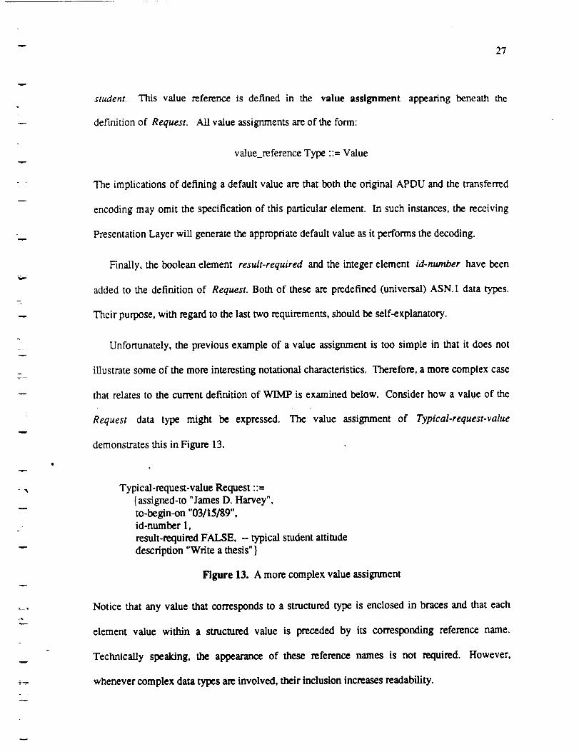
Unfortunately, the previous example of a value assignment is too simple in that it does not
illustrate some of the more interesting notational characteristics. Therefore, a more complex case
that relates to the current definition of WIMP is examined below. Consider how a value of the
Request data type might be expressed. The value assignment of Typical-request-value
demonstrates this in Figure 13.
Typical-request-value Request ::=
{assigned-to "James D. Harvey",
to-begin-on "03/15/89",
id-nurnber 1,
result-required FALSE, -- typical student attitude
description "Write a thesis" }
Figure 13. A more complex value assignment
Notice that any value that corresponds to a structured type is enclosed in braces and that each
element value within a structured value is preceded by its corresponding reference name.
Technically speaking, the appearance of these reference names is not required. However,
whenever complex data types are involved, their inclusion increases readability.

28
3.2.3 A More Realistic Example
As the f'mal iteration of the example, a more realistic set of requirements is considered. These
requirements will motivate a fairly sophisticated ASN.I definition and will represent the
complexity one might encounter in a real application. The new requirements are as follows:
, It would be desirable to have the option of not specifying who is to carry out a given work
request if we so desire. For instance, the user of this protocol might wish to have a
particular request assigned to whoever is available at the time the work is scheduled to
commence. The specification of the assigned-to elenieni should therefore be optional.
2. Certain tasks may require the pa_cipation of more than one individual. Thus, the
assigned-to element should indicate an unbounded number of name values. Furthermore,
it is important that the user be given the ability to associate an authority hierarchy with the
individuals that are specified. In other words, the manner in which these individuals are
expressed should denote a "chain of command."
3. The date (or rather time) that a request is to be executed should be expressed in a more
accurate manner. A mere date is not very specific.
u
!
w
W
i
I
mllll
4. A Result should indicate more than just success or failure. It should_=indicate the
names of the individual(s) who attempted to perform the task. This may differ from the
originai uest. "thecontents a hoUid V accor i ::tn 0a tcome.Xfa
work request is executed successfully, the time of completion should be given. If a request
fails, an explanation of the failure would be desirable.
5. Each request should possess an indication of its relative importance.
° Certain work requests may be of a proprietary nature and the ability to indicate when this
condition exists is desirable. Furthermore, in these instances it might be necessary to
II
m
11
mm
m
u
-- 29
v
m
i
._,._
w
y_
encrypt the description of a request itself.
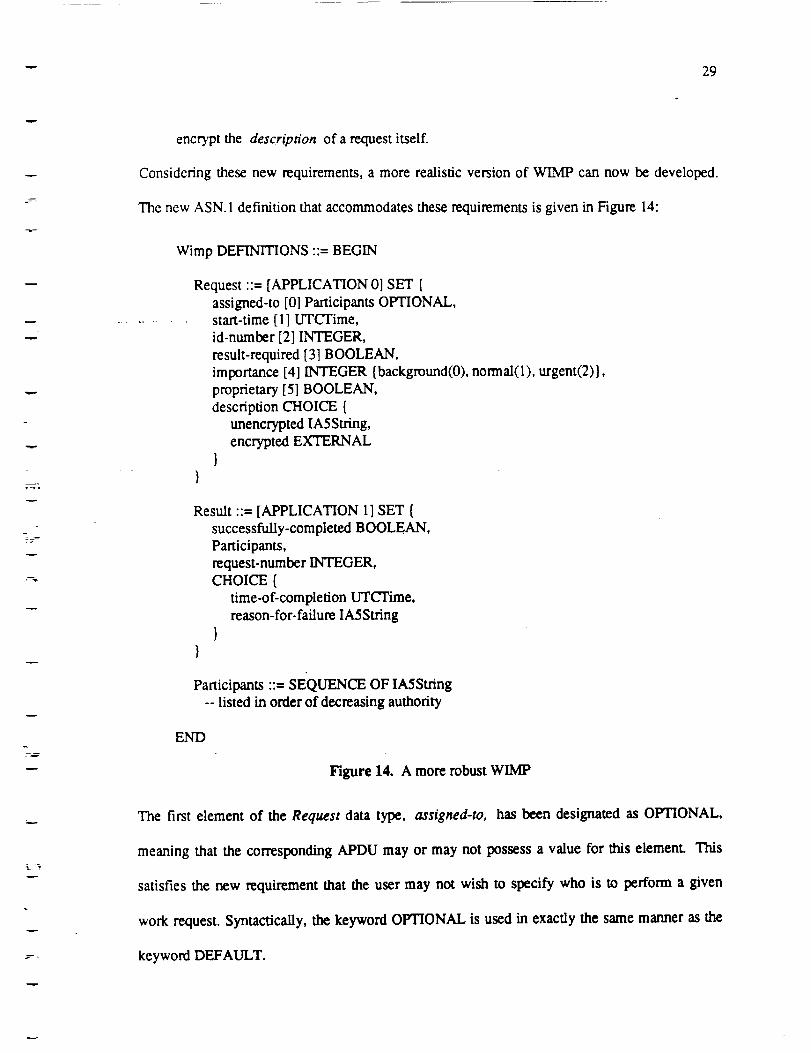
Considering these new requirements, a more realistic version of WIMP can now be developed.
The new ASN. 1 definition that accommodates these requirements is given in Figure 14:
Wimp DEFINITIONS ::= BEGIN
Request ::= [APPLICATION 0] SET {
assigned-to [0] Participants OtrHONAL,start-time [1] UTCTime,
id-number [2] INTEGER,
result-required [3] BOOLEAN,
importance [4] INTEGER {background(0), normal(l), urgent(2)},
proprietary [5] BOOLEAN,
description CHOICE {
unencrypted IA5String,
encrypted EXTERNAL
}
Result ::= [APPLICATION 1] SET {
successfully-completed BOOLEAN,
Participants,
request-number INTEGER,CHOICE {
time-of-completion UTCTime,
reason-for-failure IA5String
}
Participants ::-- SEQUENCE OF IA5String
-- listed in order of decreasing authority
END
Figure14. A more robustWIMP
The first element of the Request data type, assigned-to, has been designated as OPTIONAL,
meaning that the corresponding APDU may or may not possess a value for this element. This
satisfies the new requirement that the user may not wish to specify who is to perform a given
work request. Syntactically, the keyword OPTIONAL is used in exactly the same manner as the
keyword DEFAULT.

3O
Thetypeof the assigned.to element has also been changed from a simple IASString to the
structured type Participants. Participants is defined as a SEQUENCE OF IASStrings. Like the
previous example of a sequence, the order of elements within a sequence-of type is considered
significant. Yet, all of the elements of a sequence-of must be of the same type, and the number of
these elements is unbounded. The sequence-of type models a collection of variables whose types
are the same, whose number is unknown or large, and whose order is significant. It is clear that
this fulfills the second requirement. Since the order of the elements within the Participants type
is significant, one can list an arbitrary number of individuals in order of decreasing authority.
The application protocol has the assurance that this order will be preserved during transfer.
With respect to the third requirement, the start-time element has been introduced in lieu of
our earlier date. Its type is UTCTime, a predefined ASN. I useful type that provides a standard
means of representing time. ISO 8824 defines the UTCTime type as:
N
m
U
W
L_
v
mm
UTCTime ::--- [UNIVERSAL 23] IMPLICIT VisibleString
Figure 15. Useful Definition of UTCTime
The VisibleString is a character subset of ASCII, and the notation [UNIVERSAL 23] is the tag.
The keyword IMPLICIT indicates a tag inheritance property that will be explained later.
The UTCTime type may be used to represent a time value expressed as a sequence (in non-
ASN.I terms) of juxtaposed characters. The syntactic format of a UTCTime data value can
assume one of the following forms: !
Wll
W_
m_

w 31
YYMMDDhhmmZ
YYMMDDhttmmssZ
YYMMDDhhmm +- hhmm
YYMMDDhhmmss +- hhmm
Figure 16. Syntactic forms of UTCTime
The first two consist of a calendar date followed by a time specification whose precision is either
to the minute or to thesecond. The Second tWOi:epresent a local time and a differential from
coordinated universal time (UTC). 7 Note that YY, MM, DD, hh, mm, and ss all stand for the
digits that one would naturally assume. The notation "+-" refers to the alternative condition:
eittier the character "+" or the character "-". Finally, the character Z (for Zulu) serves to
distinguish the first two formats from the latter two which represent local time values and the
local differential. Regardless of which format is used, this type provides the protocol with a more
specific concept of time. Thus, the third requirement is satisfied;
The Result type has been drastically modified to meet the specifications of the fourth
requirement. It is now a SET consisting of four elements. The first indicates whether the
corresponding work request was completed successfully. The second contains the names of the
individuals who attempted to perform the request. The third identifies the request to which the
result corresponds, and the fourth element introduces a new structured type, the CHOICE.
The ASN. 1 choice type is used to model a variable whose type may vary within the bounds of
a known and modest set of alternatives. Each element appearing within the choice type indicates
one such alternative. In the previous example, the fourth element consists of either a time-of-
w
7. UTC used to be referred to as Gre.enwichMeanTime.

32
completion value or a reason-for-failure value.
The choice type is analogous to a union declaration in C. One can think of our Result type as
a variant record. The successfully-completed element corresponds to what is traditionally referred
to as the tag field, and each element within the choice type represents a specific variant. In fact,
if this definition was given to the ASN. 1 compiler, it would generate a C struct declaration for the
Result set type and an embedded union declaration for the choice type element. Yet unlike the C
union, the ASN.1 choice is, by requirement, self describing. Consequently, the element
successfully-completed and the element proprietary are redundant.
The fulfillment of the fifth and sixth requirements is reflected in the last three elements of the
Request type. The importance element is an integer value indicating the relative priority of a
request. The z'ccompanying named number list (the text enclosed in braces) indicates the
domain of meaningful values and their respective connotations. These named numbers are not
significant in the definition of the type. Their purpose pertains to the value notation exclusively,
although they do provide a valuable means of documentation. The proprietary element is a
boolean value indicating whether a reque.st is proprietary. According to this value, it is assume
that the element description is either encrypted or unencrypted. The unencrypted version is
simply an IASString while the encrypted value is of the predefined, useful type EXTERNAL.
To explain how the EXTERNAL type facilitates this encryption, a brief digression is
necessary. One of the primary services of the Presentation Layer is the negotiation of transfer
syntaxes. Before any useful data may be exchanged across a presentation connection, the two
presentation protocol entities that wish to communicate must first agree on the use of a transfer
syntax. Since each is aware of its user's abstract syntax and the available encoding rules that it is
capable of applying, agreement is simply a matter of reaching consensus on the preferred transfer
syntax. When this negotiation process has been completed, the association of an abstract syntax
'Wl
J
W
wig
T--
W
m
!
w
iil
11
L
u
_m
n

-- 33
v
v
r
T
and a transfer syntax is referred to as a presentation context. [31
The second concept that must also be understood is the def'mition of an object identifier and
an information object. An information object is defined by ISO 8824 as "a well-defined piece of
information, definition, or specification which requires a name in order to identify its use in an
instance of communication." The ASN. 1 standard itself is an information object. An object
identifier is a value used to designate an information object. It is distinguishable from all other
such values because each object identifier uniquely identifies its corresponding information
object. Object identifier is a predefined universal type of ASN. 1.
The creation of each individual value of the object identifier type is performed in a very
formal manner. Only certain registration organizations possess the necessary authority to
associate an object identifier with an information object. The domain of each respective
organization's authority obeys a gee-structured hierarchy. The manner in which an object
identifier value is expressed also reflects this structure, described in Annexes B, C, and D of ISO
8824. A partial view of this structure is given in Figure 17.
w

W
34
i
root
ccitt lso joint-iso-ccitt
standard registration-authority member-body identified-organization
f_m
Figure 17. Object Identifier Tree
Each interior node of the tree represents a domain of authority. Each leaf represents a specific
information object. Both the name of each node and the numbers associated with each arc
provide a means of uniquely identifying a specific information object. Each value of the object
identifier type consists of a sequence of these arc and/or node values. For instance, the
information object FTAM may be expressed as:
{iso standard 8571 }
Figure 18. Object Identifier Value for FTAM
An object identifier value therefore represents a method of identifying a path from the root node
to a descendent. More important, an object identifier value may denote any registered abstract
syntax and a supporting set of encoding rules. This later point is particularly important with
respect to the encryption example.
The purpose of using the ASN.1 external type is to force the current presentation context to
change. The external type itself is represented as an ASN. 1 sequence, indicated in Figure 19.
!
1it
'-IlF
I
alF
W
1ira
IP
4
U
IlR

w
35
EXTERNAL ::= [UNIVERSAL 8] IMPLICIT SEQUENCE {direct-reference OBJECT IDENTIFIER OPTIONAL,
indirect-reference INTEGER OPTIONAL,
data-value-descriptor ObjectDescriptor OPTIONAL,
encoding CHOICE {
single-ASNl-type [0] ANYoctet-aligned [I] IMPLICIT OCTET STRING,
arbitrary [2] IMPLICIT BIT STRING
}J
Figure 19. EXTERNAL type def'mition
For the purpose of understanding the encryption example, it is sufficient to simply recognize that
the external type contains an encoded value (expressed as a CHOICE type), along with either an
object identifier value that identifies the new abstract syntax and encoding rules or an integer
value that identifies what the new presentation context should be.
The encryption example could be constructed as follows: [41
1. An object identifier for BER already exists within the object identifier tree.
2. A second set of encoding rules could be registered explicitly.
with these new rules would consist of applying the Basic
applying an encryption algorithm to the resulting bit stream.
decryption knowledge would be distributed selectively.
The algorithm associated
Encoding Rules and then
Obviously, the necessary
and one to support both ISO 8825 and these new encoding rules.
The encrypted description of a work request can now be embedded within an encoding. When
the receiving Presentation layer attempts to decode a value of this external type, it can make the
appropriate adjustment to its presentation contexL
If this description is not clear, the reader might find the foUowing analogy helpful, s If a
3. Two presentation contexts could be. subsequently established; one to support just ISO 8825,

J
36
Ira,
presentation connection represents a dialogue between two individuals, then the presentation
context would represent the agreement they must make regarding what language they are going to
speak. Assuming that the basic phonetic properties of any natural language are not sufficient to
determine its identity, these two people must agree on which language or languages they are
going to use before "striking up a conversation? _ Let us assume that they agree to speak in either
English or French and that presently they are speaking English exclusively.
Consider what would happen if the following situation arose. In the course of the dialogue,
one of these individuals would like to express the cliche, "That's life!". However, instead of
uttering this English phrase, this person would like his comment to capture a specific ambiance.
He therefore decides to say "C'est la vie!". In this analogy, the embedded French phrase
corresponds to the encrypted data value of the external type. Its value must consist of a
representation of the phrase itself and an indication that a change in the interpretation context is
necessary. In other words, the listener must be explicitly told that some French is about to be
spoken if he is to interpret the comment correctly. (Remember, it is assumed that phonetics is not
an identifying characteristic.) This illustrates the primary purpose of the ASN.1 external type. It
forces a change in the current presentation context so that a data value of a different transfer
syntax can be correctly interpreted. 9 In this French example, the phrase value would provide
either an object identifier designating that the French "encoding rules" must be applied or a
presentation context identifier indicating that the current presentation context must be changed to
French.
W
I
m
V
8. This analogy was provided by Maurice Smith who is the International Representativeof the ANSI X3T2 DataInterchange Sub-committee.
9. It is important to recognize the EXTERNAL type serves as only a temporary "escape" to a new presentationcontext. The presentation layer protocol directly supportsmore long term context control mechanisms.
I
W

-- 37
3.2.4 Other ASN.I Types
To complete this presentation of ASN. 1, a brief description of each remaining ASN. 1 type is
given that was not depicted within any of the previous examples.
3.2.4.1 The BIT STRING Type
The BIT STRING type may be used to model a variable whose binary format is unspecified
and whose length, in bits, is either unspecified or not a multiple of eight. Consequently, the
binary data of a bit string may not fit into an integral number of octets. A bit map indicating set
membership is a perfect example of a variable that would use the bit string type. The definition
of Light in Figure 20 illustrates how the BIT STRING type is used.
L
Light ::-- BIT STRING {red(0), orange(I), yeUow(2), green(3),blue(4), indigo(5), violet(6)}
-- An instance of light is defined by its spectrum colors;-- a bit value of one indicates that the corresponding color is present
Figure 20. Using a BIT STRING
The text between the braces, referred to as a named bit list, does not influence the def'mition of
the type. It is used solely in the value notation and provides a means of documenting the type.
3.2.4.2 The OCTET STRING Type
The OCTET STRING type may be used to model a variable whose format is unspecified and
whose length, in bits, is unspecified but known to be a multiple of eight. The definition of the
EXTERNAL type, Figure 19, uses the OCTET STRING type to model the octet-aligned
alternative of its encoding element. The OCTET STRING type may also be used to model
specific character string types which are not already predefined by ASN. 1 (see section 4.4.6).

38
3.2.4.3 The NULL Type
The ASN. 1 NULL type represents a valueless placeholder, wi_n a sequence, for instance,
the NULL type may indicate the absence of a specific element, Annex E of ISO 8824 provides
the following example:
Patientldentifier ::= SEQUENCE {
name VisibleString,
roomNumber CHOICE {INTEGER,
NULL -- if an out-patient}
}
Figure 21. Using the NULL Type
In this context, the NULL type merely provides an alternative means of expressing that the
roomNumber element as OPTIONAL. H0wever,_the two methods should not be viewed as
equivalent. In this case (where a NULL type is used), the length of the corresponding encoding
will be longer, lo
W
IlR
V
W
,,.imw
W
I
3.2.4.4 The SELECTION Type
The SELECTION type may only be Used in conjunction with a CHOICE type. It is used to
create a new type which is derived from the selection of an alternative within a choice type.
Consider the following CHOICE type:
10. It is not necessarily true that using NULL in lieu of oFrIONAL will always yield a longer encoding. If similar
types were to appear in the SEQUENCE and OPTIONAL is used, or if the SEQUENCE was instead a SET, explicittagging would be required to disambiguate the definition.
m
J
J
!
l
W
m
u
w
w
g_
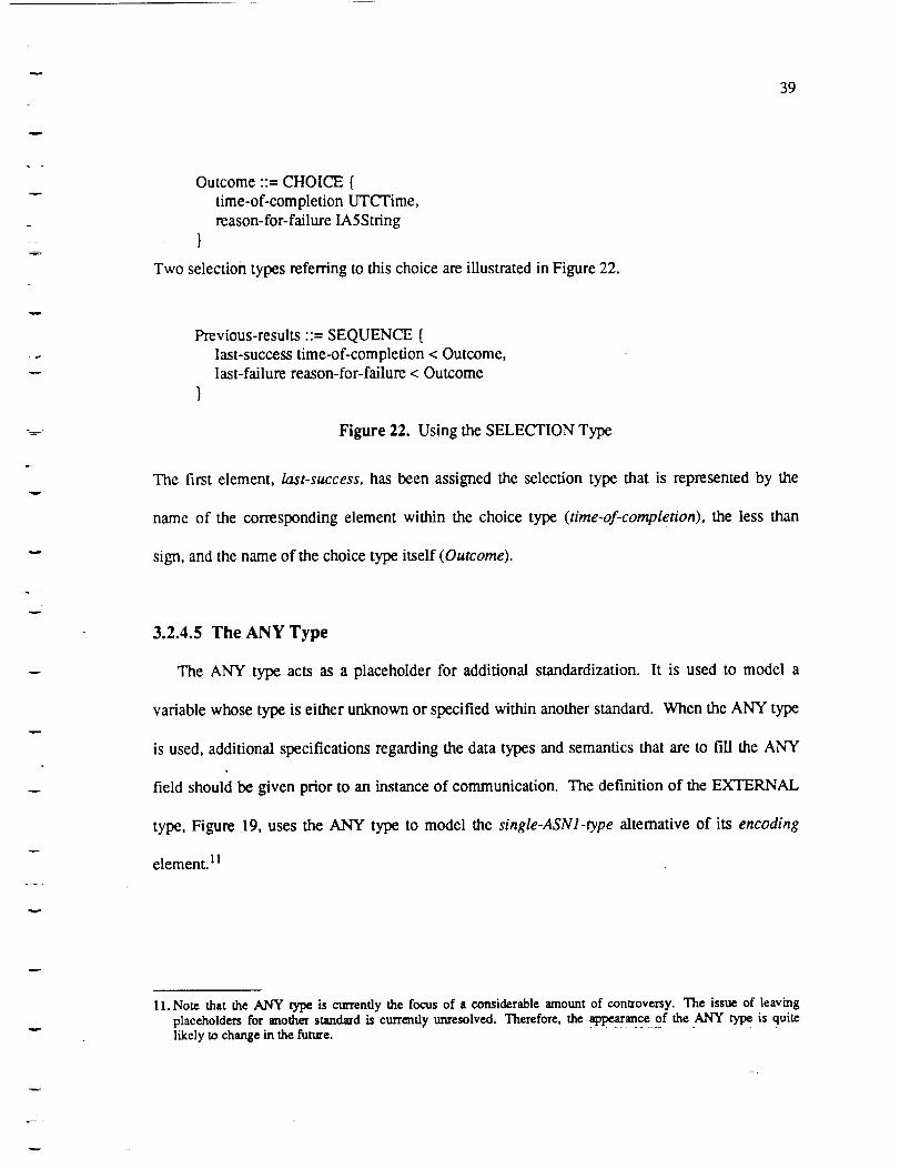
39
7
Outcome ;:= CHOICE {
time-of-completion UTCTime,
reason-for-failure IA5String
1
Two selection types referring to this choice are illustrated in Figure 22.
w
-._.._ -
v
v
Previous-results ::= SEQUENCE {
last-success time-of-completion < Outcome,last-failure reason-for-failure < Outcome
}
Figure 22. Using the SELECTION Type
The first element, last-success, has been assigned the selection type that is represented by the
name of the corresponding element within the choice type (time-of-completion), the less than
sign, and the name of the choice type itself (Outcome).
3.2.4.5 The ANY Type
The ANY type acts as a placeholder for additional standardization. It is used to model a
variable whose type is either unknown or specified within another standard. When the ANY type
is used, additional specifications regarding the data types and semantics that are to fill the ANY
field should be given prior to an instance of communication. The definition of the EXTERNAL
type, Figure 19, uses the ANY type to model the single-ASNl-type alternative of its encoding
element. 11
v
1 l. Note that the ANY type is currently the focus of a considerable amount of controversy. The issue of leaving
placeholders for another standard is currently unresolved. Therefore, the appearance of the ANY type is quite
likely to change in the future.
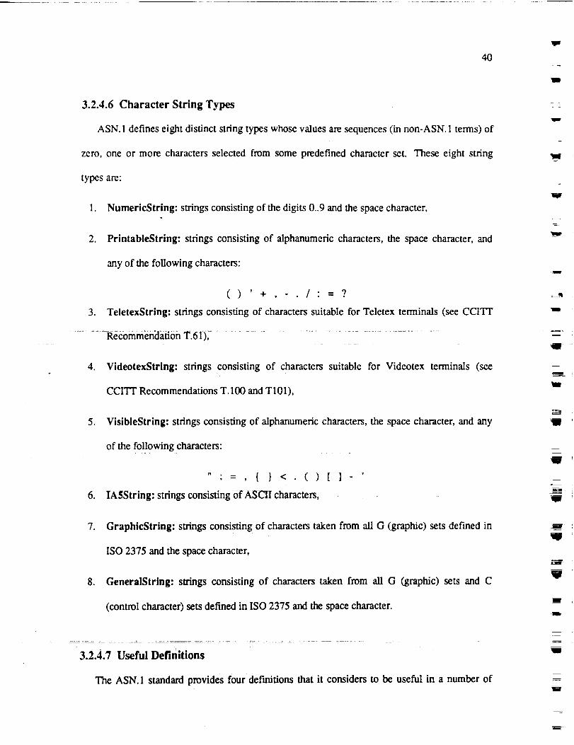
40
3.2.4.6 Character String Types
ASN. 1 defines eight distinct string types whose values are sequences (in non-ASN. 1 terms) of
zero, one or more characters selected from some predefined character set. These eight string
types are:
1. NumericString: strings consisting of the digits 0..9 and the space character,
2. PrintableString: strings consisting of alphanumeric characters, the space character, and
any of the following characters:
() '+, /'=?
3. TeletexStrlng: strings consisting of characters suitable for Teletex terminals (see CCIq"I"
Recommendation T.61),
4. VideotexString: strings consisting of characters suitable for Videotex terminals (see
CCI'VI' Recommendations T. 100 and T 101),
, VisibleString: strings consisting of alphanumeric characters, the space character, and any
of the following characters:
,
".=, { } <.()
IASString: strings consisting Of ASCII characters,
[]-
1111
W
W
m
I
g
tll
J
m
W
7. GraphicString: strings consisting of characters taken from all G (graphic) sets defined in
ISO 2375 and the space character,
8. GeneralString: strings consisting of characters taken from all G (graphic) sets and C
(control character) sets defined in ISO 2375 and the space character.
m
V
3.2.4.7 Useful Definitions
The ASN. 1 standard provides four definitions that it considers to be useful in a number of
m
m
w
W

41
applications: GeneralizedTime, UTCTime, EXTERNAL, and ObjectDescriptor. The only
one of these useful types that has not been illustrated within an example as of yet is the
GeneralizedTime type. Like the UTCTime type, a GeneralizedTime value is represented as a
VisibleString. It specifies the date and time as either a local time, a UTC time, or a combination
of the two.
3.3 Basic Encoding Rules (BER)
The Basic Encoding Rules standard, ISO 8825, defines a specific technique for encoding data
values corresponding to ASN.1 data type definitions. As mentioned in the overview, a BER
encoding consists of a sequence of octets partitioned into an identifier-length-contents tuple,
indicated in Figure 8. Within this section, the bit-level details of how this is accomplished are
explained. But first, some numbering conventions must be established.
3.3.1 Numbering Conventions
To explain the details of an encoding it is often necessary to refer to specific bits within an
octet. To do this, the same numbering scheme used in ISO 8825 is employed. Specifically, the
bits of any octet will be numbered from eight to one, going left to right. The significance of each
bit increases as one moves from fight to left. It will also be necessary to refer to specific octets
within an octet sequence. Here, the reverse numbering order is used. If n octets represent an
encoding, the leftmost octets will be numbered one, and the fightmost will be numbered n.
Figure 23 illustrates this convention.

42
mostsignificantoctetOCTET #1
11111I187654321
most significant bit
OCTET #2
II 187654321
Figure 23. Bit and Octet Numbering
OCTET #3
IIII Ill87654321
least significant octet
OCTET #11
87654321
least signet
W
Mv
w_v
m
3.3.2 Tagging
It is appropriate that the examination of the Basic Encoding Rules begin by analyzing the
structure and the content of the identifier octet(s). This requires an understanding of the concept
of a tag. Four classes of tags may be associated witlaanyeiement or data type in ASN.I:
universal, application, context-specific, and private. Data types possessing a universal tag are
predefined by ISO 8824. Like most programming languages, these predefined types provide a
means through wMch other type definitions may be constructed.
universal types along with their respective tag numbers.
Table 1 lists all the ASN. 1
W
N
lg
W
in
V
= l
W
W
i
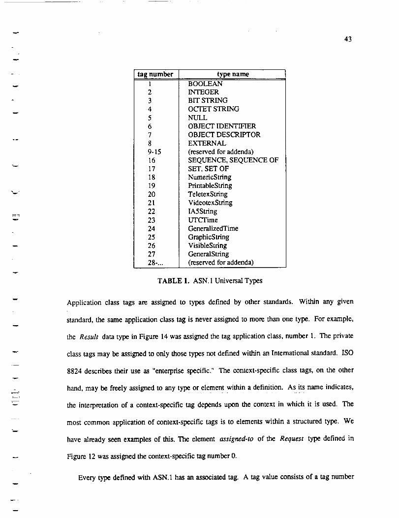
43
_m
tag number type name1
23
4
5
6
7
8
9-15
16
17
18
19
20
21
22
23
24
25
26
27
28-...
BOOLEAN
INTEGERBIT STRING
OCTET STRING
NULL
OBJECT IDENTIFIER
OBJECT DESCRIPTOR
EXTERNAL
(reserved for addenda)
SEQUENCE, SEQUENCE OFSET, SET OF
NurnericString
PrintableString
TeletexString
VideotexString
IASStringUTCTime
GeneralizedTime
GraphicString
VisibleStringGeneralString
(reserved for addenda)
TABLE 1. ASN. 1 Universal Types
Application class tags are assigned to types defined by other standards. Within any given
standard, the same application class tag is never assigned to more than one type. For example,
the Result data type in Figure 14 was assigned the tag application class, number 1. The private
class tags may be assigned to only those types not defined within an International standard. ISO
8824 describes their use as "enterprise specific." The context-specific class tags, on the other
hand, may be freely assigned to any type or element within a definition. As its name indicates,
the interpretation of a context-specific tag depends upon the context in which it is used. The
most common application of context-specific tags is to elements within a structured type. We
have already seen examples of this. The element assigned-to of the Request type defined in
Figure 12 was assigned the context-specific tag number 0.
Every type defined with ASN. 1 has an associated tag. A tag value consists of a tag number
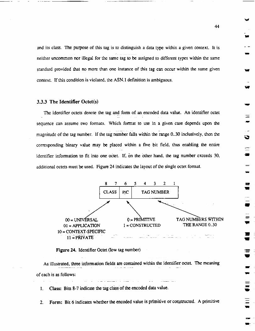
44
It
and its class. The purpose of this tag is to distinguish a data type within a given context. It is
neither uncommon nor illegal for the same tag to be assigned to different types within the same
standard provided that no more than one instance of this tag can occur within the same given
context. If this condition is violated, the ASN. 1 definition is ambiguous.
"Ill'
w
3.3.3 The Identifier Octet(s)
The identifier octets denote the tag an_d form of an encoded data value. An identifier octet
sequence can assume two formats. Which format to use in a given case depends upon the
magnitude of the tag number. If the tag number falls within the range 0..30 inclusively, then the
corresponding binary value may be placed within a five bit field, thus enabling the entire
identifier information to fit into one octet. If, on the other hand, the tag number exceeds 30,
additional octets must be used. Figure 24 indicates the layout of the single octet format.
w
m
l
r_
J
W
8 7 6
CLASS P/C I
.J00 = UNIVERSAL
01 = APPLICATION
10 ; CONTF.XT-$PECINC......... , =:
1i = PNVATE = - -
0--P_RI ITIVE
1 = CONSTRUCTED
5 4 3 2 1
TAG NUMBER I
TAG NUMBERS WITHINTHE RANGE 0..30
Figure 24. Identifier Octet (low tag number)
As iUusta'ated, three information fields are contained within the identifier octet. The meaning
of each is as follows:
1. Class: Bits 8-7 indicate the tag class of the encoded data value.
2. Form: Bit 6 indicates whether the encoded value is primitive or constructed. A primitive
l
w
_i
m
J
m
In
!m
,!D
V
m!
l,
!
V
i
I
J

45
.
form indicates that the contents octets contain a direct representation of the data value. A
constructed form indicates that contents octets are the complete encoding of another data
value. In other words, the subsequent contents octets contain embedded identifier-length-
contents sequences.
Tag Number: For tag numbers falling within the range 0 to 30 inclusive, bits 5-1 of the
leading (and only) octet designate this value. For tag numbers greater than 30, bits 5
through 1 contain the value 11111. This reserved bit pattern indicates that an extension of
additional octets is required to hold the tag number. Bits 7-1 of each subsequent octet
whose 8 bit is set to 1, up to and including the first octet whose 8 bit is set to zero, will be
concatenated to form the binary tag number value. Figure 25 graphically illustrates this.
LEADING OCTET
87
I classlP/clllX111 I11
TAG NUMBER= I
SUBSEQUENT OCTETS
1 87 1 87
] Ill I ..... [01
/I I ..... I I
Figure 25. Identifier Octet (extended tag number)
3.3.4 The Length Octet(s)
The purpose of the length octets is to determine the end of an encoding. They explicitly
indicate how many contents octets have been used in the encoding, or, alternatively, they signify
that this length is unknown but deducible. In the explicit case, they contain the binary value
corresponding to the exact number of contents octets that follow. In the case where this number
is unknown, they contain a reserved bit pattern indicating that the contents octets arc delimited
with a special EOC sequence. An EOC sequence consists of two octets whose binary values are

46
lira
zero. == =
Like the identifier octet(s), the length octet(s) may be expressed in more than one format: the
short form, the long form, and the indefinite form. The use of a specific format is determined by
three conditions: the form of the encoding (primitive or constructed), whether the number of
contents octets is known in advance and the magnitude of this number. Primitive encodings are
restricted from using the indefinite form since this would preclude the appearance of two
consecutive "zero octets" within their contents octets. However in the case of a constructed type,
the EOC octets always fall at the point in the encoding where the next identifier octet would be.
Since zero is not a valid identifier octet (the UNIVERSAL 0 tag does not exis0 there is no
ambiguity. The choice of which format to use with constructed encodings is left to the user's
discretion, Figure 26 illustrates the layout of these three forms.
= =
w
m
W
!II
W
m
m
V
I
m
m
11w
!

v
w
47
v
8
SHORT FORM
7
Number of contents octets
LONG FORM
w
v
w
Leading Octet _ _ Subsequent Octets
8 7 1 8 1 8 1
[ 1 l Number oflength octets [ J ..... _ J
/ j \Number of contents octets = I I ..... I
INDEFINITE FORM
8 7 1
1_ 0 0 0 0 0 0 0
Figure 26. Length Octet Forms: short, long and indefinite
In the short form, the number of octets that the length information occupies is one. Bit 8 is
required to be zero, and bits 7-1 contain the number of contents octets. Obviously, this form may
be used only when the number of contents octets is less than or equal to 127. In the long form,
the number of octets that the length information occupies can be anywhere from 2 to 127. In the
leading octet, bit 8 is always set to 1, and bits 7-1 indicate the number of subsequent length octets
required. Since the bit pattern 11111111 has been reserved for possible future extension, the
maximum number of subsequent octets is 126. As illustrated in Figure 26, these subsequent
octets are concatenated to form the binary value indicating the number of contents octets used in
the encoding. Finally, the indefinite form requires only one octet containing the reserved bit

487"
W
pattern indicated above. In relation to the other formats, this bit pattern represents the long form
with zero subsequent length octets. From a logical perspective, this makes sense. No need for
subsequent length octets exists since the contents octets are delimited by an EOC sequence.
3.3.5 The Contents Octet(s)
In a primitive encoding, the data value is directly represented by the contents octets. This
may not, and in many instances will not, be exactly the same as the original native representation,
depending on the host environment, the data type, and the magnitude of the value itself. For
example, ISO 8825 specifies that negative integers are always in two's complement form and that
the character values of an IA5String are in ASCII.12 In a const_cted encoding, the contents octets7
do not contain a direct representation of the data value, but instead contain further encodings.
These nested encodings can in turn be constructed if necessary.
W
=_
m
_Li
3.3.6 Examples
This section illustrates the content and the structure of the contents octets by examining the
encodings of typical values pertaining to some of our previous AsN. 1 definitions.
3.3.6.1 Encoding an Integer Value
_e easiest example i_-iUuswa_e would _ the encoded values of the Result data type
-apPearing in Figure 10. According to the comment below its definition, a success is represented
by the value 0, and a failure is represented by -1. The encoding of a success value (0) is depicted
in Figure 27:
12. Many other characteristics of I$O 8825 also influence this change in representation. For example, integers arealways encoded in the minimal number of octets, etc.
I
W
lira
mJl
im
llr
lip
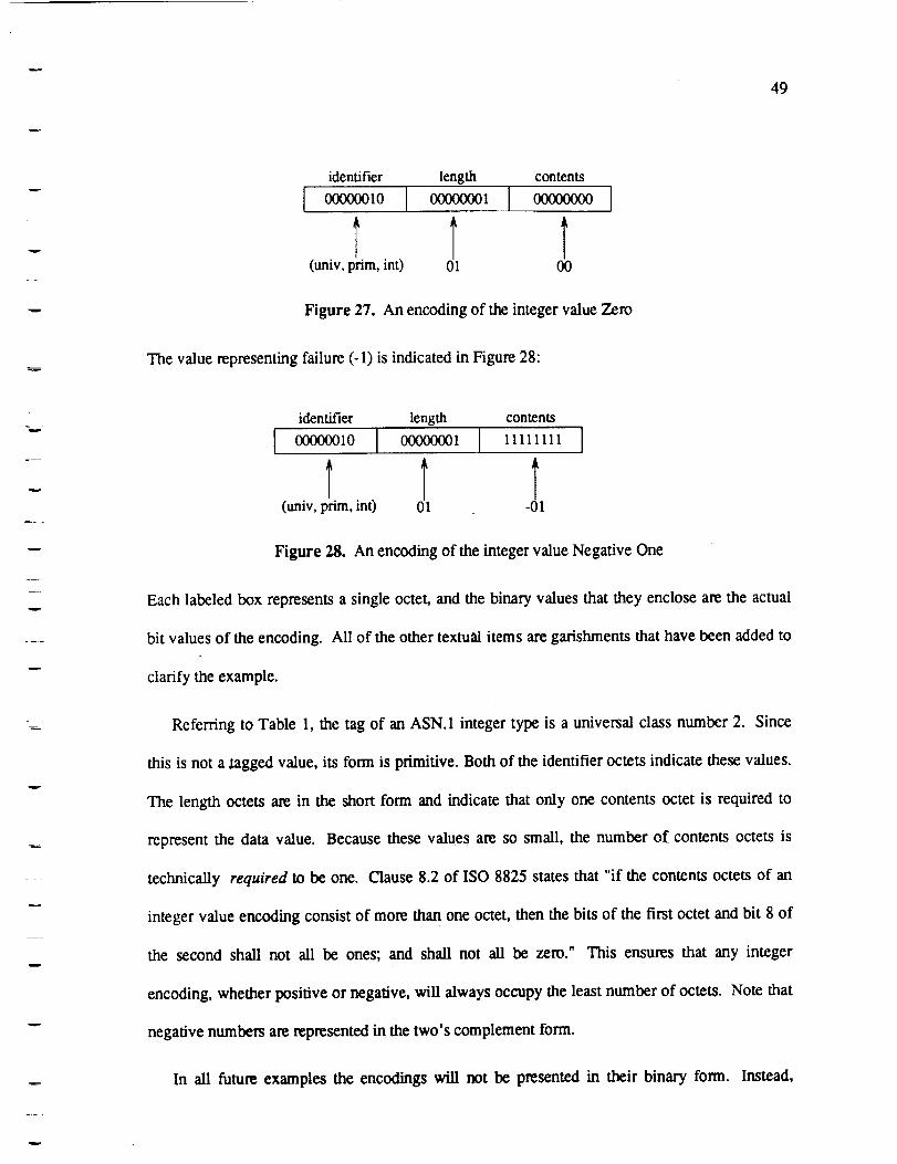
49
w
identifier length contents
I 00000010 I
(univ, prim, int)
ooooooolI I
Figure 27. An encoding of the integer value Zero
The value representing failure (-1) is indicated in Figure 28:
1
l_
identifier length contents
I 00000010 i 0(X)(gg_l I 11111111 I
(univ, prim, int) 01
Figure 28. An encoding of the integer value Negative One
Each labeled box represents a single octet, and the binary values that they enclose are the actual
bit values of the encoding. All of the other textual items are garishrnents that have been added to
clarify the example.
1
Referring to Table 1, the tag of an ASN.1 integer type is a universal class number 2. Since
this is not a tagged value, its form is primitive. Both of the identifier octets indicate these values.
The length octets are in the short form and indicate that only one contents octet is required to
represent the data value. Because these values are so small, the number of contents octets is
technically required to be one. Clause 8.2 of ISO 8825 states that "if the contents octets of an
integer value encoding consist of more than one octet, then the bits of the first octet and bit 8 of
the second shall not all be ones; and shall not all be zero." This ensures that any integer
encoding, whether positive or negative, will always occupy the least number of octets. Note that
negative numbers are represented in the two's complement form.
In all future examples the encodings will not be presented in their binary form. Instead,

50
w
textual abbreviations are used to represent the identifier octet(s) (as above), decimal numbers are
used to designate the length octets, and the contents octets are represented in a form resembling
the data type being encoded.
3.3.6.2 Encoding a Sequence
As a more substantial example, consider Request that appears in Figure 10. A data value of
this type consists of a simple sequence of three IA5Strings. For the typical value:
{"John Doe", "03/25/89", "Plant growth experiment"}
its encoding would be as follows:
IDENTIFIER
(univ, const, 16)
LENGTH CONTENTS
45 "J %
IDa_ LENGTH CONTENTS
(univ, prim, 22) 8 'John Doe'
IDENTIFIER LENGTH CONTENTS
(univ, prim, 22) 8 '03/25/89'
IDENTIFIER LENGTH CONTENTS
(univ, prim, 22) 23 'Plant growth experiment'
Figure 29. An encoding of a sequence value
" The fi_t=iden_ _si_fies_at_e _t_or_e encoded data value'is a unive_ Ciass
number 16. As indicated in Table 1, this corresponds to the sequence type. Since sequences are
structured, the form is constructed and the contents octets consequently contain embedded
=
W
w
!
mV
mm
m
W
Im
W
w
IB
identifier-length-contents tuples, fii-flae-above dia-gram, indenting is used to represent this
nesting. The length octet of the outer most tuple indicates that the total number of contents octets
is 45. This includes all Octets associated with the nested tuples. The three embedded encodings
m• =
mm
W
m
W
J

i ,
51
are of the type universal class 22. As indicated in Table 1, this tag number corresponds to the
type IA5String. Their contents octets would contain the appropriate ASCII values.
3.3.6.3 A More Complex Encoding
As a final example, the encoding of a hypothetical value of the Result data type appearing in
Figure 14 is given below. Assuming that this value is in response to our previous work request, 13
for the result value:
{successfuUy-completed FALSE,
{"John Doe"],
request-number 100,reason-for-failure ',John lacks green thumb"}
its encoding would be as follows:
13. Ignore the fact that these two type def'mitions appear in different versions of WIMP.

w
52
IDENTIFIER
(appl, const, 1)
LENGTH
4 ts S
s
"IDENTIFIER
(univ, const, 17)
CONTENTS
42 " "J %
IDENTIFIER LENGTH CONTE(univ, prim, 1) 1 FF
IDENTIFIER LENGTH CONTENTS
(univ, const, 16)"IDENTIFIER""10",,, ,-" LEN G_" ""CO__
:_(unN.)_rim, 22) 8 'John Doe'
IDENTIFIER LENGTH CONTENTS
(univ, prim, 2) I 100
ID_ LENGTH
(univ, prim, 22) 22
CONTENTS
'John lacks green thumb'
Figure 30. Encoding a result value
This encoding might appear somewhat verbose, or even redundant in places. This reflects the
relationship between constructed encodings and tagged values, that is, values corresponding to a
type definition explicitly tagged. The first identifier octet denotes that the tag of the encoded
value is an APPLICATION 1. From the original ASN. 1 definition we know that this tagged type
is a set of four elements. However, before the encodings for these four elements can appear, the
encoding for the set type (i.e. UNIVERSAL 17) must come first. This reveals an important
aspect about tagging, namely, an explicit tag does not supplant the existing one but merely
augments it. Although it is known in this context that a WIMP data value with a tag of
APPLICATION 1 is a set of four elements, this information is not implicit with respect to an
encoding. Therefore, each of the explicit tags increases the length of the encoding. This
characteristic can be changed by adding the IMPLICIT keyword to the type definition.
w
mw
m
I!
n
l
U
l
I
m_
W
I
I
w
mlit
Rlr
11,
i,
J

53
v
w
v
v
w
3.3.7 The IMPLICIT Keyword
The IMPLICIT keyword may be used in an ASN. 1 type definition to yield a more economical
encoding. As a feature of ASN.1, it is an example of one way in which ISO 8824 and ISO 8825
are tied together. This, in a sense, violates the abstraction of the data types by making an issue of
the encoding process visible to the user of ASN.1. ISO 8825 states that if the keyword
IMPLICIT does not appear within the type definition of a tagged value, then the form of its
encoding shall always be constructed. This was the case in the previous example. If, on the other
hand, the IMPLICIT keyword is used, then the form of the encoding will be constructed only if
the base encoding is constructed; it shall be primitive otherwise. This enables the encoding of a
tagged value to connote type information otherwise requiting an additional embedded encoding.
The following example will clarify this explanation.
In the definition of Result, it might be preferable that the tag value:APPLICATION 1
indicate that the encoded data type is a set, thus allowing the removal of the embedded encoding
to the UNIVERSAL 17 tag. The addition of the IMPLICIT keyword makes thispertaining
possible:
Result ::= [APPLICATION 1] IMPLICIT SET {
successfully-completed BOOLEAN,
Participants,
request-number INTEGER,
CHOICE {
time-of-completion UTCTime,
reason-for-failure IA5String
}}
Figure 31. Adding the IMPLICIT keyword
This new definition would yield the more compact encoding given in Figure 32.

54
w
IDENTIFIER
(appl, const, 1)
LENGTH CONTENTS
IDENTIFIER CO -
(univ, prim, 1) I 0
IDENTIFIER
(univ, const, 16)
LENGTH CONTENTS
Js
"IDENTIFIER
(univ, prim, 22) 8 'John Doe'
IDENTIFIER LENGTH(univ, prim, 2) 1
CONTENTS100 ....
IDENTIFIER LENGTH
(univ, prim, 22) 22
CONTENTS
'John lacks green thumb'
Figure 32. A New Encoding of Result
Notice that the total length of our encoding is now two octets shorter.
3'4 Pending Modifications
All ISO standards are subject to revisions=that occur on a four year cycle. For mature
standards, the modifications resulting from each cycle seldom constitute major changes.
However, considering the relative youthfulness of both ASN. 1 and BER, the changes associated
with their first revision will most l|l_dy be quite significant. The draftaddendums that define
these proposed modifications are ISO 8824/DAD1 [51and ISO 8825/DAD 1. [61The highlights of
each of these proposals are discussed within this section along with th6 escalating controversy
over the ASN. 1 macro notation.
J
= =
W
W
I
I
iI
i
.Im
I
J
i
i
I
w
I
RI
W
m
I
1IV
'It
I
m
I
w

!
55
3.4.1 Tag Defaults
Experience in using ASN. 1 indicates that the IMPLICIT keyword is used more often than not.
Moreover, the current notation supporting the concept of implicit versus explicit tagging is
asymmetric: the keyword IMPLICIT is defined while the keyword EXPLICIT is not. To
alleviate both of these problems, ISO 8824/DAD 1 proposes a new notation whereupon either the
IMPLICIT keyword or the EXPLICIT keyword may be applied to all tags within a module
definition by default. The specification of this tag default option appears immediately after the
keyword DEFINITIONS in the module header. For instance, if the user wanted all of the tags
within the WIMP module to be IMPLICIT by default, its module header would be changed as
follows:
WIMP DEFINITIONS IMPLICIT TAGS ::= BEGIN
Figure 33. A Module with the IMPLICIT Tag Default
Conversely, all of the tags within the WIMP module could be defined as explicit by simply
substituting the keyword EXPLICIT for the keyword IMPLICIT. In all cases, EXPLICIT may be
used in exactly the same manner as IMPLICIT. Consequently, individual tag specifications may
override any default by using either keyword as necessary. When no tag default is specified,
EXPLICIT is assumed.
3.4.2 Enumerated Types
Within one of the previous definitions of WIMP, Figure 14, the Request sequence type
contains the integer element importance. One problem associated with this definition of
importance is that the domain of its meaningful values is expressed as a named number list.
Since named numbers have no "influence on the definition of a type, a compiler generated
implementation may not use this information. Consequently, the encode and decode functions

"i¢
56=.__.
W
produced by the compiler will not check if values corresponding to the importance element fall
within the proper range (i.e., 0..2).
ISO 8824]DAD 1 proposes that an enumerated type defirfition be added to ASN.1. Its tag
would be the universal class, number 10. Using the suggested syntax, our previous importance
element could be defined as indicated in Figure 34.
im po rtance ENUMERATED {background(0), normal(l), urgent(2) }
Figure 34. An Enumerated Type
The encoding of a value of this enumerated type is defined to be that of the integer value with
which it is associated.
3.4.3 Importing and Exporting
Although an example of this has not shown, in any given module definition it is currently
possible to reference types and values defined in other modules. As an illustration, if another
module definition were to require the use of WIMP's Request data type, it could do so by
specifying the name of the module, followed by a "." and the name of the type:
New_request_type ::= Wimp.Request
Figure 35. An External Type Reference
ISO 8824/DAD 1 proposes a new notation that would enable a user to exert explicit control over
the visibility of type references and value references. The proposal requires that a module
definition be partitioned into three sections: an EXPORT list, an IMPORT list, and an assignment
list. As an example, assume that the Participants data type of the previous WIMP definition were
already defined within another module, People, and that it is desired that the definitions of the
Request and the Result data types be visible to other protocol standards. The new definition of
w
II1
J
i
llF
m=
W
mi
w
I
!
V
!
!11

57
w
w
WIMP would be as follows:
Wimp DEFINITIONS ::= BEGIN
EXPORTS Request, Result
IMPORTS Participants FROM People
Request ::= [APPLICATION 0] SET {
assigned-to [0] Participants OPTIONAL,start-time [1] UTCTime,
id-number [2] INTEGER,
result-required [3] BOOLEAN,
importance [4] INTEGER {background(0), normal(l), urgent(2)},
description CHOICE {
unencrypted IA5String,
encrypted EXTERNAL
}}
Result ::= [APPLICATION 1] SET {
successfully-completed BOOLEAN,
Participants,
request-number INTEGER,
CHOICE {time-of-completion UTCTime,
reason-for-failure IA5String
}
END
Figure 36. Using EXPORT and IMPORT
w
3.4.4 Reals
The most glaring deficiency associated with the current definition of ASN. 1 is the absence of
real types. To fill this void, ISO 8824/DAD 1 and ISO 8825/DAD 1 propose that a new real type
be added with the tag universal class, number 9. The keyword REAL is used to designate the
type as illustrated in Figure 37.
w
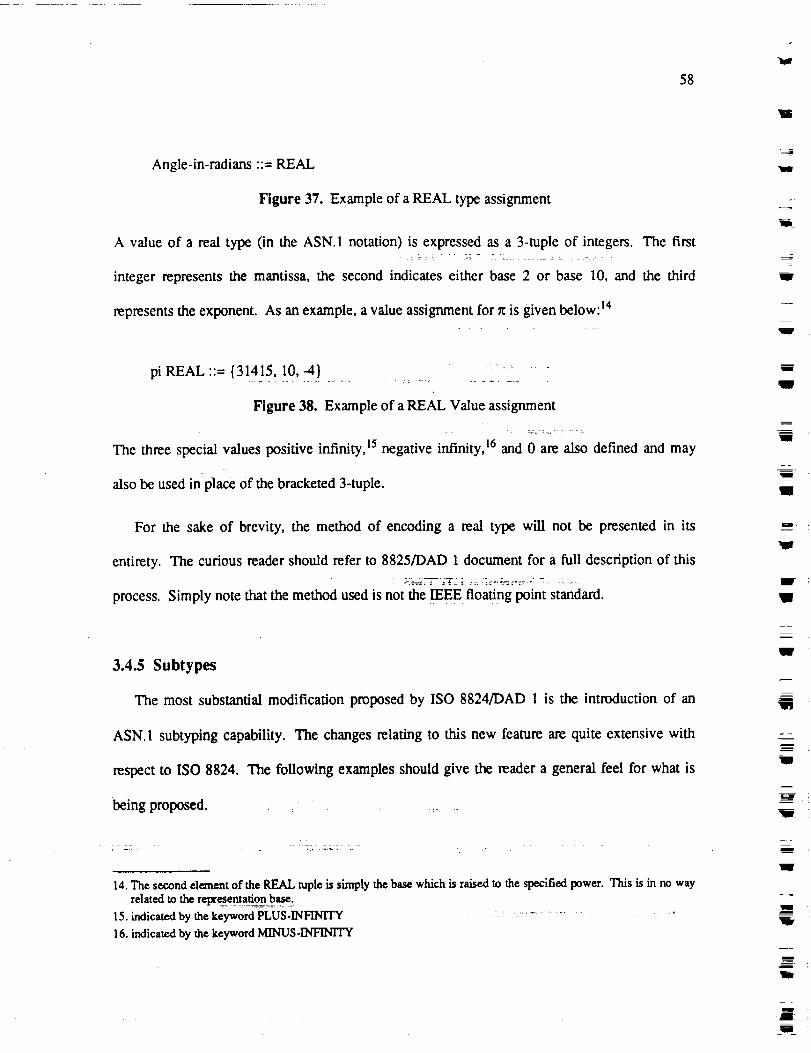
58
W
Angle-in-radians ::= REAL
Figure 37. Example of a REAL type assignment
A value of a real type (in the ASN. 1 notation) is expressed as a 3-tuple of integers. The first
integer represents the mantissa, the second indicates either base 2 or base 10, and the third
represents the exponent. As an example, a value assignment for x is given below: 14
3i
1In
W
pi REAL ::= {31415, 10, -4}
Figure 38. Example of a REAL Value assignment
The three special values positive infinity, is negative infinity, t6 and 0 are also defined and may
also be used in place of the bracketed 3-tupie.
For the sake of brevity, the method of encoding a real type will not be presented in its
entirety. The curious reader should refer to 8825/DAD 1 document for a full description of this
process. Simply note that the method used is not the IEEE floating point standard.
3.4.5 Subtypes
The most substantial modification proposed by ISO 8824/DAD 1 is the introduction of an
ASN.1 subtyping capability. The changes relating to this new feature are quite extensive with
respect to ISO 8824. The following examples should give the reader a general feel for what is
being proposed ......
14. The second element of the REAL tuple is simply the base which is raised to the specified power. This is in no way
related to the representationbase.
15. indicated by thekeywordPLUS-INFINITY =: "....... _ ........ :16. indicated by the keyword MINUS-iNFINTFY
Ew
W
I
D
I
wg,
I!
J
i
W
m
m
111
!
m
W
m
"m=
U

7
59
The draft addendum defines a subtype as "a type whose values are specified as a subset of the
values of some other type (the parent type)". A subtype specification is composed of alternatives
where each alternative is a value set or a constraint. A subtype is created by either explicitly
enumerating a subset of values taken from a parent type, constraining the range of values from
the parent type, constraining the size of a parent type, or by using any combination of these three
methods.
In the previous definition of WIMP, Figure 14, there are several instances where a subtyping
capability might be useful. First, within both the Result and Request data types, the protocol
designer may want to constrain the possible values of an id-number to fall within the range
0..127. This would enable its encoded value to occupy only one byte. Second, it may be
desirable to limit the number of Participants that may be assigned to any given request to 10.
The two type assignments within Figure 39 could be used to meet these new requirements.
wRequest-number ::= INTEGER (0..127)
Participants ::= SEQUENCE SIZE (1 .. 10) OF IA5String
Figure 39. Using Subtypes
w
3.4.6 The Macro Notation
Annex A of ISO 8824 defines a macro notation that can be used to extend ASN. 1. Although
it is currently an official part of the standard, the details of the ASN.1 macro notation are
presented here because they are the focus of a co_idemble amount of controversy. Their present
disposition within the ASN.1 standard is precarious. This is exemplified by the fact that the
X3T2 subcommittee, which is the United States constituent responsible for maintaining the
ASN.1 standard, has developed the official position that the use of macros be "strongly
deprecated. ''[rl Consequently, the future of the ASN. 1 macro notation is uncertain.

60
ThemacronotationaUowstheuserof ASN.1to defineanewnotationthroughwhichASN.I
typesmaybeconstructedandreferenced,andvaluesof thesetypesmaybespecified.Themacro
definitionprocessrequiresthattheuserspecifyanewandcompletesyntaxfor definingall types
supportedby themacro,a correspondingsyntaxfor specifyinga valueof this type, andthe
resultingtypeandvaluefor all instancesof thismacrovaluenotation.Thespecificrulesthat
determinehow this definition processis expressedarequite tediousand are thereforenot
presented.Instead,anexamplethatpertainsto thedefinitionof WIMPisexplored.
Supposethedesignerof theWIMPprotocolwishestodefineanewdatatypethatrepresentsa
primaryrequestandanalternativerequest.Thealternativeis to beattemptedonly in theevent
that the primaryrequestfails. Certainly it is feasible to represent this new data type as a
SEQUENCE of two elements. However, for reasons of personal taste, this person would like to
express this new type with a syntax of his own design. The macro notation would be used to
accomplish this as indicated below:
REQUEST-WITH-ALTERNATIVE MACRO ::= BEGINTYPE NOTATION ::--
"plan-a" "="
type (Plan-a-type)
"plan-b" "-"
type (Plan-b-type)VALUE NOTATION ::=
"C "plan-a" "="value (Plan-a-value Plan-a-type)
......, plan-b ......=
value (Plan-b-value Plan-b-type) .........<VALUE SEQ_CE {Plan-a-type, Plan-b-type} ::=
{Plan-a-value, Plan-b-value}>
l|)fl
END
Figure 40. A Macro Definition ::
This macro could subsequently be used to define types andvaiues as follows:
1ira
Wr
W
w
M
111
I
_m
ll["
z
W
w
V
J
m
!

61
w
Request-pair ::= MACRO REQUEST-WITH-ALTERNATIVE
plan-a = Request
plan-b = Request
Request-value Request-pair ::=
(plan-a = ....
plan-b = ...)
Figure 41. Using a Macro Def'mition
In the above Figure, the elipses refer to any value of the Request data type.
m
Many problems associated with the macro notation have been currently identified. For
example, since macro definitions may contain subsequent macro references, the ability to parse
the macro notation is questionable. Also, ambiguities relating to the resulting type and tag of a
macro may arise. Is] With respect to the future, the current definition of the ASN.1 macro notation
is quite likely to change. These problems are explored further in chapter 5.
w
u
62
ll
I
4. The ASN.1 Compiler
Now that most of the details of both ASN.1 and BER are understood, it is important to
establish an understanding of how their use might be realized within an implementation. The
details of an ASN. 1 compiler are described within this section.
Before delving into these de_isitiS necessary that the followihg objective be clearly stated.
The author does not consider this compiler implementation to be the solution to the ASN.1
problem and the reader should not interpret the ensuing explanations as such. As mentioned
earlier, the usefulness of an ASN. 1 compiler can be limited, especially when the protocol being
implemented is fairly stable. In these situations it is practical to write the encoding and decoding
routines by hand as tiffs often yields a faster implementation. An ASN. 1 compiler is therefore not
always the "best" means of developing an implementation. Secondly, there are many viable
approaches to the problem of incorporating this encoding and decoding functionality into a
Presentation Layer implementation. This compiler represents one of many possible solutions, its
value depends upon the insight it provides into the relationship between these two standards and
the OSI Reference Model.
4.1 Physical Specifications
The compiler is written in the C programming language and is approximately 5000 lines in
length. Its front end was developed using the Unix utilities Lex and Yacc. The compiler accepts
an ASN.1 module definition as input and generates two C files as output: an include file
w
1
mi
m
ma
!
_I
W
lIB
w
lit
_z
m
JJ

63
w
. r
w
containing the C declarations of the APDU's, and a code file containing the two C functions
encode and decode. A rim-time library also provides a melange of general purpose routines.
Unfortunately, the compiler does not support the entire ASN.1 standard; the macro notation,
character sets other than IA5Strings, useful types, and external references are not presently
implemented.
4.2 Generating Declarations
To create a transfer syntax, the ASN.1 compiler depends upon a precise knowledge of the
APDU representations. It is therefore appropriate that the compiler assumes the responsibility of
creating these declarations on behalf of the Application Layer. This provides a more robust
implementation since it ensures that the ASN. 1 data type definitions will be always consistent
with the actual APDU representations. Clearly this is desirable, considering that the relative
benefit provided by an ASN.1 compiler hinges upon its ability to minimize the effects that
modifications to the abstract syntax may cause. The reader's understanding of this mapping from
the ASN.1 definitions to the APDU declarations is most important; it represents the first bridge
between an ASN. 1 definition and a working implementation.
Assuming that the reader is familiar with the C programming language, the clearest means of
describing this aspect of the compiler is through an example. Let us examine the APDU
declarations generated from the module definition of WIMP that appears in Figure 10. These are
shown in Figure 42.
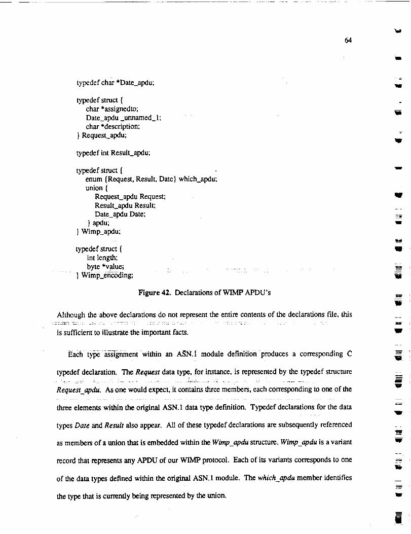
64
typedefchar*Date_apdu;
typedefstruct{char*assignedto;Date_apdu _unnamed_ 1;
char *description;
} Request_apdu;
typedef int Result_apdu;
typedef struct {
enum {Request, Result, Date} which_apdu;union {
Request_apdu Request;
Result._apdu Result;
Date_apdu Date;
} apdu;
} Wimp_apdu;
typedef struct {
int length;
byte *yalue;
} Wimp_encoding;
Figure 42. Declarations of WIMP APDU's
Although the above declarations do not represent the entire contents of the declarations f'fle, this
is sufficient to illustrate the important facts.
Each type assignment within an ASN.1 module definition produces a corresponding C
typedef declaration. The Request data type, for instance, is represented by the typedef structure
Requestapdu. As one would expect, it contains three members, each corresponding to one of the
three elements within the original ASN. 1 data type def'tnition. Typedef declarations for the data
types Date and Result also appear. All of these typedef declarations are subsequently referenced
as members of a union that is embedded within the Wimp_apdu structure. Wimp_apdu is a variant
record that represents any APDU of our WIMP protocol. Each of its variants corresponds to one
of the data types defined within the original ASN. 1 module. The which_apdu member identifies
the type that is currently being represented by the union.
=
Ill
I1
=
!
qW
HB
m
U
W
W
H
mm
W
mw
W
m
W
m
II

65
_m
w
w
There are two subtle but important aspects of the above declarations that should be noted.
First, the order of these typedef declarations does not correspond to the original ASN. 1 definition.
This is because forward references, while permitted within ASN.I, are not permitted within C.
Consequently, the declaration of Date_apdu must precede the declaration of Requestapdu.
Second, notice that the name of the second member of the Request_apdu structure is
unnamed 1. Since the second element of the original ASN. 1 definition of the Request data type
was not named, the corresponding C name must be supplied by the compiler itself. This
illustrates why the use of named types within an ASN.I element list enables the compiler to
generate more readable C code.
4.3 Generating Code
The compiler generates two routines which are to be _subsequently integrated into the
Presentation Layer. Since actual C code of each is very detailed it will not be presented. The
reader may refer to Appendix A where a complete listing of the code generated for this particular
example is given. Within this section the logical operation of each function is discussed in a very
general sense. The corresponding function declarations are given below.
encode_Wimp (decoding, encoding)
Wimp_apdu *decoding;
Wimp__encoding *encoding;
decode_Wimp (encoding, decoding)
byte *encoding;
Wimp_apdu *decoding;
Figure 43. The Encoding and Decoding Functions

66
4.3.1 Encoding
The encoding function accepts the decoding argument as input and produces the encoding
argument as output. The encoding process occurs in two phases. The purpose of the first phases
is to calculate all of the length octet values of the encoding to be generated and to allocate an
encoding buffer of the proper size. ms task is performed by examining the contents of each
value within the given APDU and making the appropriate run-time calls. These computed length
values are inserted into a table which already contains the type octet values for each type that has
been defined in the ASN.1 module. These values are subsequently extracted from this table in the
later phase as the actual encoding is generated. The fact that the inner length octets of an ASN. 1
encoding determine the values of the outer length octets explains why this length calculation
phase is necessary. In other words, it is not possible to build an encoding from the inside out
since the starting offset within the encoding buffer is unknown. The second phase focuses upon
building the actual encoding. The type and length values from the previously built table are
inserted into the encoding buffer and the actual values of the APDU are passed to the appropriate
run-time routines which insert the contents octet values.
4.3.2 Decoding
The decoding function accepts the encoding argument as aninput and produces the decoding
argument as output. The decoding process is controlled by a finite state machine, implemented as
a state table. Each entry of the state table contains an expected type octet value and a set of
transitions. The finite state table for the Wimp module of Figure 10 is giyen below:
J
V
W
g
m
m
111
W
Ig
V
m
m
v
w
R
m
!!i
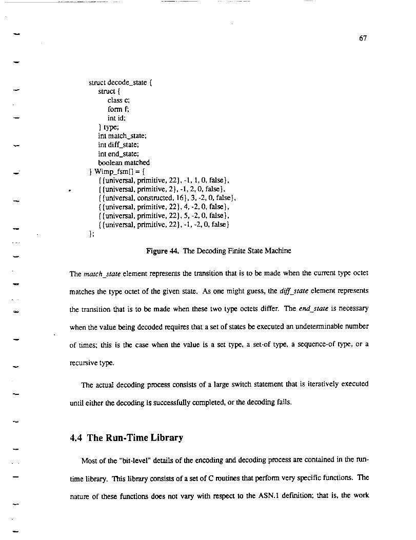
67
v
struct decode_state {
struct {class c;
form f;
int id;
} type;int match_state;
int diff_state;
int end_state;boolean matched
} Wimp_fsm[] = {
{ {universal
{ {universal{{universal
{ {universal
{{universal
{{universal
t;
primitive, 22}, - 1, 1, O, false },
primitive, 2 }, - 1, 2, O, false },constructed, 16}, 3, -2, O, false},
primitive, 22}, 4, -2, O, false},
primitive, 22}, 5, -2, O, false},
primitive, 22 }, - l, -2, O, false }
Figure 44. The Decoding Finite State Machine
The match state element represents the transition that is to be made when the current type octet
matches the type octet of the given state. As one might guess, the diff_state element represents
the transition that is to be made when these two type octets differ. The end_state is necessary
when the value being decoded requires that a set of states be executed an undeterminable number
of times; this is the case when the value is a set type, a set-of type, a sequence-of type, or a
recursive type.
The actual decoding process consists of a large switch statement that is iteratively executed
until either the decoding is successfully completed, or the decoding fails.
4.4 The Run-Time Library
Most of the "bit-level" details of the encoding and decoding process are contained in the run-
time library. This library consists of a set of C routines that perform very specific functions. The
nature of these functions does not vary with respect to the ASN.1 del'mition; that is, the work

68
performed by these run-time routines is applicable to the encoding and decoding of almost all
ASN. 1 def'mitions. An overview of these run-time routines is given below.
The ASN. 1 compiler's run-time library consists of the following routines:
l
w
1. Dec_typlen : This function decodes the type and length octets of an an encoding. It
supports both the five bit form as well as the extended form of the type octet(s) as well as
the short, long, and indefinite forms of length octet(s).
2. Enc_typlen : This function decodes the type and length octets of an encoding. It supports
both the five bit form as well as the extended form of the type octet(s) as well as the short,
long, and indefinite forms of length octet(s).
3. Len len • This function determines the length of a length octet value. In other words, itw
........ determines how many !en_ octets are required to hold a given len_ value. This routine
is called by the encoding routine when it is computing the length of the encoding.
. lnt len • This function determines the number of contents octets required to encode a
given integer value.
5. Enc int" This function inserts the encoding of an integer value into the contents octet(s) of
an encoding. In accordance with clause 8.2 of ISO 8825, the number of contents octets
produced is always the minimum required to represent the integer value.
6. Dec int" This function returns the integer value represented by the contents octet(s) of anm
.
encoding.
Enc bool • This function inserts the encoding of a boolean value into the contents octet(s)
. = -
of an encoding.
8. Dec bool • This function returns the boolean value represented by the contents octet(s) of
an encoding. A boolean value in C is declared as an unsigned char.
v
i
mw
J
I
l
lg
i
U
!W
i
lIB
m
llip
m
1

69
9. Enc ia5str • This function inserts the encoding of a IA5String value into the contents
octet(s) of an encoding.
10. Dec ia5str" This function returns the IA5String value represented by the contents octet(s)
of an encoding.
11. Enc bstr " This function inserts the encoding of a BIT STRING value into the contents
octet(s) of an encoding.
712. Dec bstr " This function returns the BIT STRING value represented by the contents
octet(s) of an encoding.
13. Enc ostr" This function inserts the encoding of a OCTET STRING value into the contents
octet(s) of an encoding.
14. Dec ostr • This function returns the OCYET STRING value represented by the contents
octet(s) of an encoding.
15. Obj_id_len : This function calculates the number of contents octets required to encode a
given OBJECT IDENTIFIER value.
16. Enc,__ostr : This function inserts the encoding of a OBJECT IDENTIFIER value into the
contents octet(s) of an encoding.
17. Dec ostr : This function returns the OBJECT IDENTIFIER value represented by the
contents octet(s) of an encoding.
4.5 Performance
As a more substantial test, the F-INITIALIZE-request PDU of the FTAM Application
protocol [91 was given to the ASN.1 compiler. A listing of this ASN. 1 definition appears in
Appendix B. With the exception of converting two Graphic String data types to IA5Strings and
70
modifyingone tag, t7 the FTAM def'mition used to conduct this performance measurement should
represent the overhead one would expect to encounter in reality. Although the other PDUs of
FTAM were reduced to integer data types, their explicit tags were left intact. Since these types
correspond to transitions within the decoding finite state machine that are never be made, the
reduction of these types is irrelevant to the measured performance.
Given the definition in Appendix B, the ASN.! compiler generated a declaration file of 194
lines and a C code ftle of 2849 lines. Running on a Sun 3/140 workstation, the time to encode the
F-INITIALIZE-request PDU was approximately 5.11 milliseconds, and the time to decode was
approximately 4.97 milliseconds. Is
U
Iil
W
t
_rag_
11
: 7 : - $7 77 z-_7
17. The explicit tag of the Protocol-Version data type was changed from [0] to [9]. This was necessary due to an
ambiguity within FTAM (see section 5.1)._ ....
18.Timings were obtained using the Unix t/m_ command whereupon the reported user and system times were
combined. The Sun workstation was dedicated to a single user when these measurements were taken.
II!
lm,
m_
u
U
!
"gl
W
m
H
Ill
mU
71
w
5. Observations
Through the process of building the compiler many insights into the ASN. 1 and BER were
obtained. This chapter presents these observations in an effort to illuminate the answer to the
question of how well ISO 8824 and ISO 8825 solve the problem of network heterogeneity. When
approaching this issue it is essential that one bear in mind the kinds of characteristics that
determine the context that makes such an evaluation possible: efficiency, clarity, applicability,
and ease of implementation.
5.1 Ambiguity
One of the more surprising discoveries that resulted from our experience with the ASN. 1
standard is the fact that the concept of ambiguity is not well defined. In the introduction of ISO
8824 a footnote indirectly addresses this issue in the context of tagging. It states:
Encoding rules always carry the tag of the type, explicitly or implicitly, with any
representation of a value of the type. The restrictions placed on the use of thenotation are designed to ensure that the tag is sufficient to unambiguously
determine the actual type, provided the applicable type definitions are available.
The reference to the tag (singular) in the above statement suggests that if ever a specific tag value
indicates more than one type in any given context, then the ASN.1 def'mition is ambiguous. If
this is indeed the correct interpretation, then the logic required to decode an encoding is LR(0).19
19. Other ASN.1 compilersrefer to decoding as "parsing".
72
Thiscoincideswith thefinitestatemachineapproachthatisusedto performthedecodingwithin
ourASN.1compiler.Yet, this sameinterpretationof ambiguityalsosuggeststhattheofficial
ASN.l definitionof FTAMisambiguous!
Lookingat thepartialdefinitionof FTAM thatappearsin AppendixB, noticethatthedata
typePDU is a choice consisting of three untagged alternatives. Since these elements do not
possess explicit tags, an encoding of this data type is identical to the encoding of the selected
alternative. Furthermore, notice that the FTAM-Regime-PDU alternative of the PDU data type is
also a choice whose first element, F-INITIALIZE-request, is assigned the tag context 0. This
means that the first tag of an encoding of the F-INITIALIZE-request PDU will always be context
0. Now note that the Protocol-Version data type that appears later in the module also possesses
the explicit tag context 0. Since the definition of this type appears at the outermost lexical level,
as does the definition of PDU, both of these data types represent potential PDUs. Consequently,
when the generated FTAM decoding routine encounters a context 0 tag as the first type octet of
an encoding, it has no way of knowing whether or not the value being represented is a Protocol-
Version PDU or a F-INITIALIZE-request PDU. In this particular case, a two tag lookahead is
necessary to disambiguate the encoding.
From the name PDU it is natural to assume that this data type is the root of the FTAM
definitions _d that _FTAM PDu'S_ori_nnate f_om-tlfis type. _heudstic_0uld=therefore be
used to resolve this particular ambiguity. However, this is clearly an assumption since there is no
construct of ASN. 1 being used to indicate that this condition holds true. In as much as forward
references are allowed in the notation, it is not possible to make this assumption based on the
mere fact that this definition appears first. Consequently, all data types that appear at the
outermost lexieal level of a module must be considered PDUs in their entirety and the ambiguity
remains. In fact, since the elements of the PDU data type do not possess explicit tags, the absence
w
J
"7
II1
'Ira
U
Wl
111
R
ilg
I_
II
I
l!
!V
u
B
W
I
W
m -
I
73
or presence of this type def'mition does not influence the formulated encodings in any way; in
other words, this data type is extraneous with respect to how an b'TAM encoding is built and
interpreted.
It is true that the FTAM standard does not intend that the Protocol-Version data type be
considered a PDU by itself. In reality it is a supporting type definition that is referenced as a
named type within other PDU definitions. Yet, the compiler has no means of making this
distinction based on the notation itself. 2° Therefore, every type def'mition that is not lexically
embedded within another type definition must be treated as a PDU. As a general approach to the
issue of ambiguity, requiring more than a single tag lookahead would require any ASN.1
compiler to generate an LR(k) implementation. This would almost certainly prevent the
realization of efficient implementations.
The ASN.1 definition of what constitutes an ambiguous instance of the notation requires
clarification.
5.2 Library Management
The unrestricted manner in which type or value def'mitions within other ASN. 1 modules may
be referenced presents another area of the ASN.1 standard that appears to be inadequately
defined. When an ASN. 1 user wishes to reference a type or value that has been def'med within
another module the External Reference construct may be used. As explained in section 3.4.3, an
external reference consists of the specification of the module name where the definition appears
and the actual name of the desired type or value. A proposal to enable the ASN.1 user to exert
20. Using the heuristic that any data type mentioned within another type is necessarily a supporting type wouldpreclude recu_sivedet'mitions.
w

74
explicit control over the importing and exporting of definitions is currently under consideration in
the pending draft addendum. However, a potential problem which has been overlooked by the
definition of this external referencing capability involves the potential for mutually dependent
module definitions. Consider the following modules:
Module-A DEFINITIONS ::= BEGIN
Type-A1 ::= BIT STRING
Type-A2 ::= SEQUENCE {
Module-B.Type-B 1
END
Module-B DEFINITIONS ::= BEGIN
Type-B1 ::= O_T STR!NG ........
Type-B2 ::= SEQUENCE {
Module-A.Type-A 1
)END
Figure 45. Mutually Dependent Modules
In this example, two ASN.1 modules are mutually dependent since each references a data type
that is defined within the other. 21 This potential for mutual dependencies requires that an ASN. 1
compiler generate partially complete intermediate code files and makes the automated processing
of these definitions extremely difficult. This problem is attributable to the absence of a well
defined library management concept within ISO 8824.
5.2.1 Linear Elaboration_-- .,_. _:._i_ _7_:-+'_-- -_- _ _ _ =-:-_L":-_-_ _'_.: _ : ..... _ _:_J-+_'--_:_=_: _ : - _ :,_ _---_ _
The problem of mutually dependent modules can be solved if ISO 8824 were to establish a
+ requirement of linear elaboration.t1°! The Ada prograrnming language effectively+: utilizes this
concept to prevent the possibility of mutual dependencies among compilation units. Elaboration
21. Mutually dependent modules appear in the X.500 series of standards.
Iiw
D--
IB_
"IW
U
I
M
11
u
M
m
w
1U
uV
'Ira
,meIIW
75
is defined as the process by which an entity is brought into existence. According to the definition
of Ada, this marks the point at which the name of a declarative item is bound to its type. The
name of an Ada entity may not be used before the elaboration of the declarative item that declares
this entity takes place. With respect to compilation units, the concept of linear elaboration
requires that a noncircu!ar ordering of all compilation units referenced, either directly or
indirectly, by a given program must exist. If no such ordering can be found, the program is
illegal.
This same requirement could be applied to the ASN. 1 standard to prevent the possibility of
mutual dependencies.
w
5.2.2 Useful Types
A set of predefined data types, called useful types, is specified in section three of ISO 8824.
Four data types are defined: Generalized time, Universal time, the External type, and the Object
Descriptor type. One problem associated with the manner in which these types are defined
concerns their disposition relative to the rest of the standard. Specifically, the means through
which their names are made visible to all module definitions is not ctear. Hence, their
relationship to the ASN. 1 standard itself is unclear. The development of a library concept would
also serve to solidify the disposition of these types.
Like Ada's package STANDARD, a predef'med module of these useful types should be
defined. This would consequently allow any ASN.1 module to explicitly import these types
whenever their use is required. Alternatively, this importing of these types could be defined as
implicit as is the case with package STANDARD. In any regard, the disposition of these types as
a predefined environment would be clarified and therefore strengthened if a module were to be
formally defined.

76
5.3 Efficiency versus Generality
The development of any standard seems to entail a perpetual series of compromises. Issues
concerning generality and efficiency are typically in conflict and a balance of the two is often the
best that can be achieved. For the most part, ASN. 1 and BER adequately strikes this balance.
However, there are particular instances where the issue of generality has been favored over
considerations of efficiency to a questionable degree.
w
Ii
W
5.3.1 Encoding Integers
As stated in section 3.3.6.1, ISO 8825 requires that all integer values be encoding in a
minimum number of octets. This requirement prohibits integer encodings from being
unnecessarily large and prevents the pathological case where an integer value may be transferred
with an arbitrarily number of leading octets thatcontain either all zeros or all ones. Nonetheless,
the cost of this decision is expensive with respect to efficiency. It has been shown that the
encoding and decoding of an ASN.1 integer value, in contrast to a simple memory copying
technique, decreases the transfer rate by a factor that ranges from 5 to 20 depending upon the host
system. [lq Moreover, in this same set of experiments it was shown that a fixed length approach
reduced the encoding time by a factor of 5-6.
To support the requirement of integer encoding minimality the nan-time system must perform
a series of checks to determine the size of each integer value. This can be accomplished through
successive range checks or successive logical operations on the leading byte of the value.
However, regardless of which approach is used, the process is unnecessarily slow. Requiring
integers to be encoded in a minimum number of bytes is ill-advised with respect to performance.
m
m
J
Ii
W
11
W
U
'll
wm
I
77
5.3.2 Object Identifiers
The encoding and decoding of object identifier values is an unnecessarily inefficient process.
Comprised of a series of numeric values, called component values, an object identifier is encoded
by representing each component value as a series of seven-bit quantities. These seven-bit
quantities are concatenated to form each component. The leading bit of each contents octet is
used to demarcate the boundaries of these component values. To further contribute to this
inefficiency, the first two components of any object are handled as a special case. Since the value
of the first component is restricted to the range 0..2, the encoding of the first two components
may be represented using the equation: 40(X) + Y where X denotes the value of the first
component and Y denotes the value of the second. This requires that the runtime routine that
performs this encoding and decoding must use its knowledge of the object identifier tree structure
to determine the values of X and Y. The application of this knowledge is expensive.
The use of seven-bit quantities is not desirable since bit masking or arithmetic shifting is
always necessary to isolate the value. Furthermore, it is not clear whether a savings of one octet
warrants the computationally expensive combination of the first two component values.
5.4 Explicit Tagging
From a philosophical perspective the concept of explicit tagging seems erroneous; it thrusts
the responsibility of preventing ambiguity onto the user. It is certainly possible to establish a
standard, canonical ordering of the type def'mitions within any module and to determine tag
values from this ordering. Consequently, a compiler could potentially generate these tags and
assume this _sponsibility instead of the user. As long as the generated tags are predictable,
economical, and unique, the users needs would be met. For example, a simple top down, left to
right sequential numbering scheme would fulfill these three requirements.

78
If such a sequential tagging generation algorithm were adopted, tag values would not be
reusable in the case of mutually exclusive contexts. Therefore, the point at which extended tag
values are necessary might arrive sooner than before and would cause the average length of an
encoding to increase, However, this point would depend on the extent of the mutually exclusive
contexts: note that the tag class values would no longer be required under this new scheme and,
therefore, the capacity of the tag id field could be extended from 0..30 to 0.. 126.
Clearly it is more desirable to have these tags generated in an automated manner since the
issue of ambiguity can be subtle and error-prone.
5.5 Sets
The only difference between the ASN.1 sequence type and the ASN.1 set type is that the
order of elements within a set is not considered significant. Therefore, opting to define a data type
as a set rather than a sequence is less restrictive. There is an intuitive tendency to equate
restrictiveness with inefficiency; after all, removing this restriction appears to allow the elements
to be reordered during transfer if this presents itself as a more efficient alternative. However, this
freedom is not more efficient. In fact the decoding of a set value is far less efficient than a
sequence due to this unpredictable ordering and, ironically, it is extremely unlikely that the order
that these elements are received will ever differ from the order that appears in the original
definition. 22.... : .....
The elements of a set value are decoding by a cycle of states within the decoding finite state
machine. This cycle is executed until it is determined that the end of the encoding has been
22. The Session Layer does not provide the _p_ility_of reordering poai0ns of a single PDU. It is therefore the
exclusive responsibility of the ASN.I compiler to perform this reordering. Yet, it is doubtful that circumstancesexist where this would be desirable.
lIW
il1
ul
IW
W
V
W
j
W_
U
_'y:_
Ill
U
tll
m_
lid
L

79
reached. As each element is encountered a boolean flag within the decoding state table, matched,
is checked and set to indicate that this decoding has occurred. After the appropriate runtime
routine performs the actual decoding, a check is made to determine if the end of the encoding has
been reached. If this check succeeds, then the matched flag of each element must be re-checked
in the state table to ensure that all the element values which were not marked as optional or had
not been assigned a default value have been represented within the encoding. If all of these
checks are successful the decoding terminates successfully.
In contrast, the decoding of a sequence value is a far less time consuming activity. Since the
order of elements is significant, decoding is simply a matter of checking each tag as it is
encountered to ensure that it matches that which is expected. If this tag check ever fails, the
decoding is terminated as a failure. Note that the end of the encoding does not require special
processing and there is no need for the matched flag to be set or checked.
The inclusion of set types in ISO 8824 appears esoteric and predicated on the need for
completeness. Their use within an actual implementation can be deceptive where efficiency is
concemed.
5.6 Macros
The Macro Notation enables a user to alter the grammar of the ASN. 1 language "on the fly".
As such, the existence of macros makes developing a conformant implementation inordinately
difficult. Although certain programming languages are capable of solving this class of
problem, 23 these languages do not possess the efficiency to make their use advisable in a network
implementation. Hence, the current definition of macros poses an obstacle.
23. programming languages like Icon or LISP

8O
Philosophically, the presence of a macro notation is inappropriate. As a descriptive
mechanism that defines the informational content of an application protocol, one of ASN. l's
most valuable benefits is the concise and accurate means of human communication that it
represents. In this respect, it is critical that its form remain standard. This enables ASN. 1 to
effectively bridge the gap between the precise communication of computers and the imprecise
communication of human beings.
With the use of macros, the ASN. 1 language can assume an amorphic form that is determined
by the personal tastes of the ASN. 1 writer. This can only serve to reduce the overall quality of
the notation itself. ..............
w
IR
Im
II
U
W
W
U
Ii!
W
W
_m
J
÷
u
W
81
6. Conclusions
From the development and application of an ASN. 1 and BER implementation, it is clear that
these two standards are fully capable of providing the data representation commonality necessary
to interconnect disparate host environments. To this extent ASN.1 and BER are successful, that
is, they achieve their intended objective by solving the problem that motivated their development.
However, a meaningful evaluation of these standards must go beyond this issue and determine
the degree to which they have succeeded. Three characteristics form the context that makes this
determination possible: clarity, ease of implementation, and efficiency.
ASN.1
achieve
improvement: sets, explicit tagging, and ambiguity.
6.1 Clarity
Clarity is an important aspect of any standard; it reflects the quality of a standard's design and
it indicates the degree to which the objectives of the standard have been recognized and achieved.
The level of clarity promoted by a standard partially determines the effectiveness of its
application. If the users of a particular standard do not possess a clear understanding of how the
standard is to be applied, the standard will most likely fail. In general, most of the features of
ASN.1 and BER are well founded and explicit with regard to their purpose. In this respect,
and BER present a relatively cleat picture of their proper application and therefore
a satisfactory degree of clarity. However, there are three areas that still require
It appears unlikely that the reordering of elements within an ASN. 1 set type will ever occur.
82
Thus, the inclusion of set types within ISO 8824, and their proper use, is unclear. This nebulous
feature represents an efficiency ambuscade since the decoding of a set value requires far more
computational effort than that of a sequence. Surprises of this nature are always unwelcome.
The ASN.1 standard should either make the inefficiency of decoding a set type explicit, or
restructure its description of the conditions under which a set type should be used in preference to
a sequence. Annex E of ISO 8824 states that:
Use a set type to model a collection of variables whose number is known and
modest and whose order is insignificant.
ilJ
w
W
W
A more appropriate description would be:
Use a set type to model a collection of variables whose number is known andmodest and where the potential for the reordering of these V_ables is known to
exist.
ASN. 1 thrusts the onus of nonambiguous definitions onto the user through its explicit tagging
capability. However, since the concept of ambiguity is not well-def'med in ISO 8824 (see section
5.1), explicit tagging represents a philosophical inadequacy of ISO 8824 and potential point of
confusion. The circumstances that determine when a given definition is ambiguous are numerous
and subtle. Even ASN.1 experts, such as those individuals who developed FTAM, are
susceptible to mistakes when it comes to the proper use of explicit tags. This makes the use of
ASN. 1 error-prone and suggests that, as a language, it is not user-friendly. The unwillingness of
ASN. 1 to confront this issue detracts from its clarity and opens the door for improper use.
............................
_J
W
U
Wl
u
U
n
6.2 Ease of Implementation
Most language purists will disagree with the position that the anticipated difficulty of
developing an implementation should influence the design of a language. Yet, programming
languages like FP and Aria serve as reminders that undesirable _nsequences can occur when
g
B

83
designers are insensitive to the needs of the implementors. To ASN. 1 and BER, the ease with
which an implementation can be developed is clearly relevant when evaluating their potential
success. The macro notation and the lack of support for library management indicate that ASN. 1
has not yet achieved its objective of processability.
The ASN. 1 macro notation represents an unimplementable "feature" that is currently the most
controversial aspect of the standard. Although there is an overwhelming consensus that the
presence of macros is undesirable, their use within existing application protocols makes their
removal from ISO 8824 difficult. Most of the current macro notation usage centers around
creating a parameterized type capability within ASN.1. In recognition of this fact, work is
currently underway to develop a parameterized (generic) type that may be offered as an
alternative to macros. If successful, the current usages could be converted and the macro notation
would disappear.
The inadequate support for library management within the ASN. 1 standard also makes the
implementation of a compiler difficult in specific cases. For example, it is unclear how the
processing of mutually dependent modules can be achieved, if at all. The establishment of a
linear elaboration concept would rectify this problem. The vague disposition of the useful types
also suggests that a formal approach to library management is needed. The definition of the
useful types as a predefined module would simplify their implementation by enabling them to be
processed as external type references.
6.3 Efficiency
The most recurring concern relating to a network design, especially OSI, is the efficiency of
its implementation. For the most part, the computational expense of encoding and decoding
appears to be relatively moderate. However, without the means to compare and contrast the use

84
of ASN.1 andBERto othermechanisms,it is hardto developa conclusiveperspectiveof just
how fast(or slow)thisprocessis. In anyregard,threeaspectsof ISO8824andISO8825are
problematic:ambiguity,the minimality of integerencodings,and the encodingof Object
Identifiervalues.
Theill-definedconceptof ambiguity within ISO 8824 represents a potential problem for any
implementation. If tag look-ahead is required to disambiguate an encoding, then the complexity
of the logic required to decode a transfer syntax increases dramatically. Under these
circumstances, an ASN.1 compiler must generate an LR(k) implementation which causes the
efficiency of the decoding process to degrade severely. At the present time, the X3T2 working
group of the United States is aware of this problem and is taking action to correct it.
Although the encoding and decoding of integers and object identifiers is not overly difficult,
their implementation is unnecessarily slow. In these two instances, the design of the Basic
Encoding Rules has favored generality at the expense of efficiency. To the ASN. I writer, a more
flexible approach would be desirable. The ability to select a fixed encoding policy versus a
minimal encoding policy would enable protocol developers to tailor their designs accordingly.
Only those protocols with a need for encoding minimality would be required to incur the expense
associated with the implementation of this feature.
6.4 Contributions7==
This thesis provides three contributions to the field of Computer Science: it offers a tutorial
on ASN.1 and BER, it brings to light several problems associated with these _w0 standards while
proposing solutions to these problems, and it lends insight into how an automated
implementation of ASN. 1 and BER may be realized.
W
J
W
W
l
j
II
-=..
W
W
111
L_41
W
U

85
6.4.1 Tutorial
ASN.I andBER arecomplexandemergingstandards.Theonly published documentation
currently available is the text of the standards. As with most international standards, this text is
difficult to read and lacks clear, illustrative explanations. Chapter three of this thesis is a more
readable tutorial intended for the practicing engineer and scientist.
6.4.2 Problems and Solutions
Three problems cited within this thesis: the inefficiency of sets, the lack of a formal approach
to library management issues and the ill-defined concept of ambiguity, were presented to the
members of the X3T224 working group in July 1989. The members of X3T2 acknowledged that
these problems were valid and requested that the author draft a technical contribution that
proposes viable solutions. This technical contribution is currently being developed and is
scheduled to be presented at the international level in October 1989.
6.4.3 Implementation Insights
Along with providing an opportunity to actively participate in the improvement of both
standards, the primary contribution of this thesis is the insights it offers into the proper design of
an automated implementation of ASN. 1 and BER. These insights are summarized below:
1. The LR(0) interpretation of ambiguity appears to be correct and allows for a finite state
machine implementation to be used in the decoding process. This is clearly desirable in
that a finite state machine solution offers greater structure, increases the readability of the
24. X3T2 is a committee of the American National Standards Institute that represents the interests of the United States
for all communication standards pertaining to the area of data interch_ge. As such. X3T2 is partially responsible
for determining and controlling the content of ISO 8824 and ISO 8825.

lip
86
generated code and yields an efficient implementation.
2. Partitioning the encoding logic into two phases, the length calculation phase and the
runtime encoding phase, is necessary for the compiler to allocate an encoding buffer of the
appropriate size before the actual encoding commences. Moreover, prior knowledge of
these length values allows the short and long forms of the length octet encodings to be used
whenever possible. This is, in many cases, preferable to the indefinite form. For those data
types which require that the end of an encoding be known in advance (i.e., set, set-of, and
sequence-of), the indefinite form is far less efficient; it requires that the EOC delimiter be
located before the decoding can begin.
3. It is appropriate that the compiler generate PDU declarations for the Application layer.
This ensures that the encoding and decoding logic will always be consistent with the actual
PDU representations. Furthermore, the representation of an APDU as a single variant
record allows only one set of decode and encode routines to be generated. Therefore, the
caller of the decoding function does not have to know which type is expected at any given
time.
ml
m
W
U
W
J
W
6.5 An Overal| ASsessment
It is clear that ASN. 1 and BER represent a viable means of solving the data representation
problem of heterogeneous networks. Yet, these standards still require a substantial amount of
improvement if their application is to be automated. Considering the youthfulness of ASN. 1 and
BER, there is hope that many of the problems stated within this thesis can be corrected before the
application of _ese standards becomes tOo pervasive. The opportunity for positive changes to be
made to both ASN. 1 and BER still exists.
H
IB
W
W
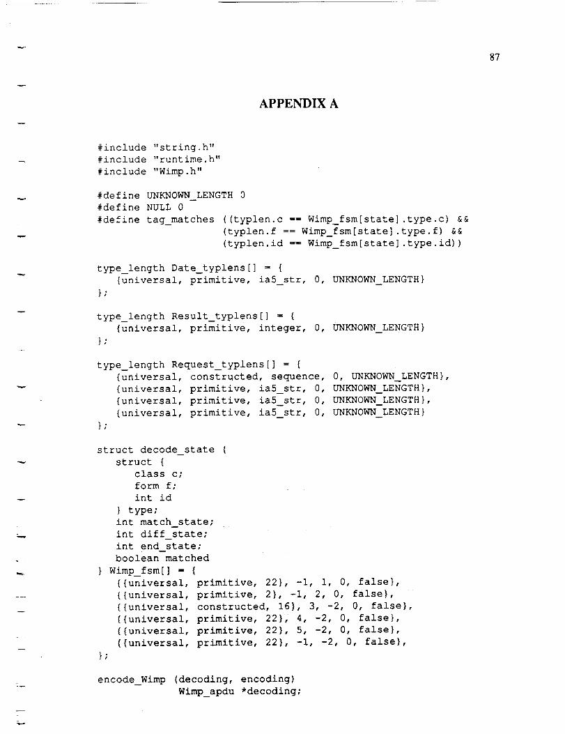
87
APPENDIX A
#include "string.h"
#include "runtime.h"
#include "Wimp. h"
#define UNKNOWN LENGTH 0
#define NULL 0
#define tag_matches ((typlen.c I= Wimp_fsm[state].type.c) &&
(typlen.f == Wimp_fsm[state].type.f) &&
(typlen.id 1= Wimp_fsm[state].type.id))
type_length Date_typlens[] = {
{universal, primitive, ia5_str, 0, UNKNOWN_LENGTH}
};
type_length Result_typlens[] = {
{universal, primitive, integer, 0, UNKNOWN_LENGTH}
}:
type_length Request_typlens[] = {
{universal, constructed, sequence, 0, UNKNOWN_LENGTH},
{universal, primitive, ia5_str, 0, UNKNOWN_LENGTH},
{universal, primitive, ia5_str, 0, UNKNOWN_LENGTH},
{universal, primitive, ia5_str, 0, UNKNOWN_LENGTH}
};
struct decode state {
struct {
class c;
form f;
int id
} type;
int match state;
int diff state;
int end state;
boolean matched
} Wimp_fsm[] - {
{{universal, primitive, 22}, -i, I, 0, false},
{{universal, primitive, 2}, -I, 2, 0, false},
{{universal, constructed, 16}, 3, -2, 0, false},
{{universal, primitive, 22}, 4, -2, 0, false},
{{universal, primitive, 22}, 5, -2, 0, false},
{{universal, primitive, 22}, -i, -2, 0, false},
};
encode_Wimp (decoding, encoding)
Wimp_apdu *decoding;
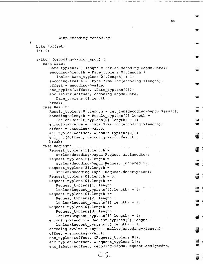
88
Wimp_encoding *encoding;
byte *offset;
int i;
switch (decoding->which_apdu) {
case Date:
Date_typlens[0].length = strlen(decoding->apdu.Date);
encoding->length z Date_typlens[0].length +
lenlen(Date_typlens[0].length) + i;
encoding->value z (byte *)malloc(encoding->length);
offset _ encoding->value;
enc_typlen(&offset, &Date_typlens[0]);
enc ia5str(&offset, decoding->apdu. Date,
Date_typlens[0].length);
break;
case Result:
Result_typlens[0].length = int_len(decoding->apdu.Result);
encoding->length z Result_typlens[0].length +
lenlen(Result_typlens[0].length) + I;
encoding->value z (byte *)malloc(encoding->length);
offset = encoding->value;
enc_typlen(&offset,__ &Result_typlens[o]); .....
enc int(&offset, decoding->apdu.Result);
break;
case Request:
Request_typlens[l].length =
strlen(decoding->apdu.Request.assignedto);
Request_typlens[2].length =
strlen(decoding->apdu. Request._unnamed_l);
Request_typlens[3].length
strlen(decoding->apdu.Request.description);
Request_typlens[0].length = 0;
Request_typlens[0].length +=
Request_typlens[l].length ÷
lenlen(Request_typlens[l].length) + I;
Request_typlens[0].length +=
Request_typlens[2].length +
lenlen(Request_typlens[2].length)_+ I;
Request_typlens[0].length +=
Request_typlens[3].length +
lenlen(Request_typlens[3].length) + i;
encoding->length _ Request_typlens[0].length +
lenlen(Request_typlens[0].length) + i;
encoding->value s (byte *)malloc(encoding->length);
offset - encoding->value;
enc_typlen(&offset, &Request_typlens[0]);
enc_typlen(&offset, &Request_typiens[i]);
enc ia5str(&offset, decoding-iapdu. Request .asslgnedto,'
mmm
m
_i
g
B
W
W
=__-
W

89
Request_typlens[l].length);
enc_typlen(&offset, &Request_typlens[2]);
enc ia5str(&offset, decoding->apdu.Request._unnamed_l,
Request typlens[2] .length) :
enc_typlen(&offset, &Request_typlens[3]);
enc ia5str(&offset, decoding->apdu.Request.description,
Request_typlens[3].length);
break;
default:
return(FAILURE);
}
return(SUCCESS);
decode_Wimp (encoding, decoding)
byte *encoding;
Wimp_apdu *decoding;
type_length typlen;
int state - 0;
byte *tmp, *offset _ encoding;
int i;
dec typlen(&offset, &typlen);
while (I) {
switch (state) {
case -2: /* FAILURE state */
return(FAILURE);
case -i: /* SUCCESS state */
return(SUCCESS);
case 0: /* Date */
if tag_matches {
decoding->apdu.Date =
(char *)dec ia5str(&offset, typlen.length);
state = Wimp_fsm[state].match_state;
decoding->which_apdu s Date;
dec_typlen(&offset, &typlen); }
else
state - Wimp_fsm[state].diff_state;
break;
case I:/* Result */
if tag_matches {
decoding->apdu.Result -
dec int(&offset, typlen.length);
state = Wimp_fsm[state].match_state;
decoding->which_apdu - Result;
dec_typlen(&offset, &typlen); }
else
state = Wimp_fsm[state].diff_state;

i
9O
break;
case 2: /* Request */
if tag_matches {
state = Wimp_fsm[state].match_state;
decoding->which_apdu I Request;
dec_typlen(&offset, &typlen); }
else
state = Wimp_fsm[state].diff_state;
break;
case 3:/* assignedto */
if tag_matches {
decoding->apdu. Request.assignedto
(char *)dec ia5str(&offset, typlen.length);
state = Wimp_fsm[state].match state;
dec_typlen(&offset, &typlen); _}
else
state = Wimp_fsm[state].diff_state;
break;
case 4:/* Date */
if tag_matches {
decoding->apdu.Request._unnamedl -
(char *)dec ia5str(&offset, typlen.length);
state = Wimp_fsm[state].match_state;
dec_typlen(&offset, &typlen) ; }
else
state = Wimp_fsm[state].diff_state;
break;
case 5: /* description */
if tag_matches {
decoding->apdu. Reques£.description
(char *)dec ia5str(&offset, typlen.length);
state = Wimp_fsm[state].match state;
dec_typlen(&offset, &typlen); }
else
state m Wimp_fsm[state].diff state;
break;
amp
W
U
Rm
I
i
m
J
I
m
i
U
w

91
APPENDIX B
ISO8571-FTAM DEFINITIONS ::ffiBEGIN
PDU ::= CHOICE {
FTAM-Regime-PDU,
File-PDU,
Bulk-Data-PDU
)
FTAM-Regime-PDU ::= CHOICE {
[0] IMPLICIT F-INITIALIZE-request,
[i] IMPLICIT F-INITIALIZE-response,
[2] IMPLICIT F-TERMINATE-request,
[3] IMPLICIT F-TERMINATE-response,
[4] IMPLICIT F-U-ABORT-request,
[5] IMPLICIT F-P-ABORT-request
F-INITIALIZE-request ::= SEQUENCE {
protocol-id Protocol-Version DEFAULT {
major {version-l},
minor revision-i
},
presentation-context-management
[i] IMPLICIT BOOLEAN DEFAULT FALSE,
service-level Service-Level DEFAULT reliable,
service-class Service-Class DEFAULT transfer-class,
functional-units Functional-Units OPTIONAL,
attribute-groups Attribute-Groups DEFAULT {},
rollback-availability Rollback-Availability OPTIONAL,
contents-type-list Contents-Type-List OPTIONAL,
initiator-identity User-Identity OPTIONAL,
account Account OPTIONAL,
filestore-password Password OPTIONAL,
checkpoint-window [8] IMPLICIT INTEGER DEFAULT 1
Protocol-Version ::= [0] IMPLICIT SEQUENCE {
major [0] IMPLICIT BIT STRING {version-l(0)},
minor [I] IMPLICIT INTEGER {
revision-l(1)
} DEFAULT revision-i
)
Service-Level ::= [2] IMPLICIT INTEGER {
reliable (0),
user-correctable (1_)
}

Service-Class ::= [3] IMPLICIT INTEGER {
transfer-class(0),
access-class(l),
management-class(2),
transfer-and-management-class(3),
unconstrained-ciass(4)
}
Functional-Units ::= [4] IMPLICIT BIT STRING {
read(2),
write(3),
file-access(4),
limited-file-management(5),
enhanced-file-management(6),
grouping(7),
recovery(8),
restart-data-transfer(9)
Attribute-Groups ::= [5] IMPLICIT BIT STRING {
storage (0),
security (i),
private (2 )
}
Rollback-Availability ::= [6] IMPLICIT INTEGER {
no-rollback (0) ,
rollback-available (1 )
}
Contents-Type-List ::--[7] IMPLICIT SEQUENCE {
document-types [0] IMPLICIT SEQUENCE OF
D b-C Ume nt-_ Ty-p e_Nam_-, ..........
constraint-sets-and-abstract-syntaxes [i]
IMPLICIT SEQUENCE {_
constraint-sets [0]
IMPLICIT SEQUENCE OF Constraint-Set-Name,
abstract-syntaxes [i]
IMPLICIT SEQUENCE OF Abstract-Syntax-Name
}
User-Identity ::= [APPLICATION 4] IMPLICIT IA5String
Account ::= [APPLICATION 5] IMPLICIT IA5String
Password ::- [APPLICATION 6] CHOICE {
IA5String,
OCTET STRING
92
wW
U
J
U
m
-_- ?
W
g
93
}
Document-Type-Name ::z [APPLICATION 7]
IMPLICIT OBJECT IDENTIFIER
Constraint-Set-Name ::= [APPLICATION 8]
IMPLICIT OBJECT IDENTIFIER
Abstract-Syntax-Name ::= [APPLICATION 9]
IMPLICIT OBJECT IDENTIFIER
F-INITIALIZE-response ::= INTEGER
F-TERMINATE-request ::= INTEGER
F-TERMINATE-response ::= INTEGER
F-U-ABORT-request ::= INTEGER
F-P-ABORT-request ::= INTEGER
File-PDU ::= INTEGER
Bulk-Data-PDU ::= INTEGER
END

94
REFERENCES
1. ISO 8824: 1987(E), "Information processing systems - Open Systems Interconnection -
Specification of Abstract Syntax Notation One (ASN.1)", International Organization forStandardization, Switzerland, December 15, 1987.
2. ISO 8825: 1987(E), "Information processing systems - Open Systems Interconnection -
Specification of Basic Encoding Rules for Abstract Syntax Notation One (ASN.1)",International Organization for Standardization, Switzerland, November 15, 1987.
3. ISO 8823: 1988(E), "Information processing systems - Open Systems Interconnection -
Connection oriented presentation protocol specification", International Organization for
Standardization, Switzerland, August 15, 1988.
4. Proposed Liaison Statement from ISO/IEC JTC1/SC21/WG6 to ISO/IEC JTC1/SC18 WG3
responding to SC21 N2813 Annex E 1 (SC18 WG3 N991), Undated.
5. ISO/IEC 8824/DAD 1, "Information processing systems - Open Systems Interconnection -
Specification of Abstract Syntax Notation One (ASN.1)", ADDENDUM 1:ASN.1
Extensions, International Organization for Standardization, Switzerland, June 9, 1988.
6. ISO/IEC 8825/DAD 1, "Information processing systems - Open Systems Interconnection -Specification of Basic Encoding Rules for Abstract Syntax Notation One (ASN.1)",
ADDENDUM 1:ASN.1 Extensions, International Organization for Standardization,Switzerland, ]une 9, 1988.
7. ANSI X3T2 - Data Interchange, Draft Minutes of Eleventh Meeting: San Diego, California,January 24-27, 1988.
8. DAF: Working Document on ASN-1, Version 2, Red Bank, New Jersey, October 1988.
9. ISO 8571/4: 1986(E), "Information processing systems - Open Systems Interconnection - File
transfer, access and management - Part 4: The file protocol specification", International
Organization for Standardization, Switzerland, August 7, 1986.
10. Reference Manual for the Ada Programming Language, ANSI/MIL-STD-1851A, American
National Standards Institute, Inc., February, 17 1983.
11. Christian Huitema and Assem Dogttri. "A High Speed Approach for the OSI Presentation
Protocol", Proceedings of the IFIP International Workshop on Protocols for High-SpeedNetworks, Zurich, Switzerland, May 9, 1989.
J
l
lIB
lid
I
W
mlid
J
J
J
w