G3600LEBW5338-00
36
G3606 • G3608 G3612 • G3616 TECHNICAL INFORMATION G3600 GAS ENGINES APPLICATION AND INSTALLATION GUIDE
-
Upload
elton-situmeang -
Category
Documents
-
view
32 -
download
3
description
Valve1
Transcript of G3600LEBW5338-00

G3606 • G3608 G3612 • G3616
TECHNICAL INFORMATION G3600 GAS ENGINES
A P P L I C A T I O N A N D I N S T A L L A T I O N G U I D E


Contents
General Data.................................................................... 2
Combustion Air System..................................................... 3
Loading on Turbocharger Inlet, Maximum..................... 5
Exhaust Gas System......................................................... 6
Loading on Turbocharger Outlet, Maximum .................. 6
Fuel System .................................................................... 7
Lubricating Oil System ...................................................... 8
Cooling Water System .................................................... 11
Block Cooling............................................................. 11
Aftercooling / Oil Cooling............................................. 12
Starting Air System ........................................................ 13
Starter Performance Curves ......................................... 13
I-R Starters ............................................................ 13
TDI Starters ........................................................... 15
Additional Data .............................................................. 17
Torsional Vibration Analysis Information ........................ 17
Flywheel & Damper Information.................................... 19
Torsional Vibration Analysis Limits................................ 19
Crankshaft Cantilever Loads......................................... 20
Unbalanced Forces and Moments ................................. 21
Rolling Torques .......................................................... 22
Part Load Strategy...................................................... 25
Sound Power Data (Mechanical, Exhaust & Air Inlet) ....... 26

Sound Power Data @ 900 rpm & 100% Load ............ 26
Sound Power Data @ 1000 rpm & 100% Load........... 27
Power Supply Requirements ............................................ 28
Reference Materials ........................................................ 28

©2006 Caterpillar® All rights reserved.
Information contained in this publication may be considered confidential. Discretion is recommended when distributing. Materials and specifications are subject to change without notice.
CAT, CATERPILLAR, their respective logos and “Caterpillar Yellow”, as well as corporate and product identity used herein, are trademarks of Caterpillar and may not be used without permission.
Foreword This section of the Application and Installation Guide lists Technical
Information for Caterpillar® engines listed on the cover of this section. Additional engine systems, components and dynamics are addressed in other sections of this Application and Installation Guide.
Engine-specific information and data are available from a variety of sources. Refer to the Introduction section of this guide for additional references.
Systems and components described in this guide may not be available or applicable for every engine.


Application and Installation Guide Technical Data – G3600 Gas Engines
©2006 Caterpillar® All rights reserved. Page 1
Technical Information – 3600 Gas Engines This guide provides technical data for the Caterpillar 3600 gas engine
models offered to the Petroleum Market. At the time of publishing, this data is correct; updates will be included periodically and this section republished. Dealers may use the Technical Marketing Information system for the most current data.
SECTION CONTENTS General Data ....................... 2 Combustion Air System........ 3 • Loading on Turbocharger
Inlet, Maximum
Exhaust Gas System ............ 6 • Loading on Turbocharger
Outlet, Maximum
Fuel System ........................ 7 Lubricating Oil System.......... 8 Cooling Water System.........11 • Block Cooling
• AC/OC Cooling Starting Air System.............13 • Starter Performance Curves
Additional Data...................17 • Torsional Vibration Analysis
Information
• Flywheel & Damper Information
• Torsional Vibration Analysis Information
• Crankshaft Cantilever Loads
• Rolling Torques
• Part Load Strategy Power Supply Requirements.28 Reference Materials ............28

Technical Data – G3600 Gas Engines Application and Installation Guide
©2006 Caterpillar® Page 2 All rights reserved.
General Data System Description Metric (English)
G3606 G3608 G3612 G3616
Cylinder Bore mm (in) 300 (11.8) 300 (11.8) 300 (11.8) 300 (11.8)
Stroke mm (in) 300 (11.8) 300 (11.8) 300 (11.8) 300 (11.8)
Displacement/Cylinder L (in3) 21.2 (1294) 21.2 (1294) 21.2 (1294) 21.2 (1294)
Total Displacement L (in3) 127.2 (7762) 169.6 (10350) 254.4 (15528) 339.2 (20704)
Rated Speed rpm 700 to 1000 700 to 1000 700 to 1000 700 to 1000
Low Idle Speed rpm 550 550 550 550
High Idle Speed - programmable rpm 700 to 1000 700 to 1000 700 to 1000 700 to 1000
Firing Order – CCW 1-5-3-6-2-4 1-6-2-5-8-3-7-4 1-12-9-4-5-8-11-2-3-10-7-6 1-2-5-6-3-4-9-10
-15-16-11-12-13-14-7-8
Crank Radius mm (in) 150 (5.9) 150 (5.9) 150 (5.9) 150 (5.9)
Connecting Rod Length
mm (in) 600 (23.6) 600 (23.6) 600 (23.6) 600 (23.6)
Reciprocating Weight
N (lbs) 670.5 (150.7) 670.5 (150.7) 670.5 (150.7) 670.5 (150.7)
Dry weight kg (lb) 15,680 (34,568) 19,000 (41,888) 25,084 (55,300) 29,892 (65,900)

Application and Installation Guide Technical Data – G3600 Gas Engines
©2006 Caterpillar® All rights reserved. Page 3
Combustion Air System System Description Metric (English)
G3606 G3608 G3612 G3616
Air Temperature @ Air Cleaner, maximum °C (°F) 45 (113) 45 (113) 45 (113) 45 (113)
High Inlet Air Temperature (low load) 54°C SCAC, warning °C (°F)
82 (180) 82 (180) 82 (180) 82 (180)
High Inlet Air Temperature (high load) 54°C SCAC, warning °C (°F)
72 (162) 72 (162) 72 (162) 72 (162)
High Inlet Air Temperature (low load) 32°C SCAC, warning °C (°F)
72 (162) 72 (162) 72 (162) 72 (162)
High Inlet Air Temperature (high load) 32°C SCAC, warning °C (°F)
57 (135) 57 (135) 57 (135) 57 (135)
Air Inlet Restriction, new/maximum mm H2O (in H2O) 125/380 (5/15) 125/380 (5/15) 125/380 (5/15) 125/380 (5/15)
Aftercooler Pressure Difference @ 100% Load, clean state kPa (psi)
3.4 (0.5) 3.4 (0.5) 3.4 (0.5) 3.4 (0.5)
Air Cleaner Style - Standard Duty without Precleaner *
1-Double Element Housing
1-Double Element Housing
1-Triple Element Housing
2-Double Element Housing
Air Cleaner Style - Heavy Duty with Precleaner *
1-Triple Element Housing
1-Triple Element Housing
2-Triple Element Housing
2-Triple Element Housing
Air Inlet Restriction, maximum limit with dirty air cleaner elements kPa (in H2O)
3.7 (15) 3.7 (15) 3.7 (15) 3.7 (15)
Air Inlet Restriction, design guideline for new clean system kPa (in H2O)
1.3 (5) 1.3 (5) 1.3 (5) 1.3 (5)
Aftercooler Pressure Difference @ 100% Load, clean state kPa (psi)
3.4 (0.5) 3.4 (0.5) 3.4 (0.5) 3.4 (0.5)
* See Price List for full descriptions of latest offerings.
Clean filters cause little air restriction. The addition of precleaners before the air cleaner extends the filter service period. A flow restriction of 0.25 to 0.75 kPa (1 to 3 in).
Air Inlet Ducting Design Guidelines:
Keep Flow Restriction of the air ducting below 0.5kPa (2 in H2O)
Ducting should have welded seam piping or seamless piping to minimize the flow restriction. PVC piping is recommended.
Ducting must withstand a minimum vacuum of 12.5 kPa (50 in H2O) for structural integrity.

Technical Data – G3600 Gas Engines Application and Installation Guide
©2006 Caterpillar® Page 4 All rights reserved.
Air Cleaner Performance Curves

Application and Installation Guide Technical Data – G3600 Gas Engines
©2006 Caterpillar® All rights reserved. Page 5
Loading on Turbocharger Inlet, Maximum
Maximum Loads for ABB VTC Turbocharger Intake
D, F & E = Adapter Weight B & K = 1/2 Hose Weight Movement (Vertical Inlet): MV = JF + ND + AB Movement (Axial Inlet): MA = YE +LK
Allowable Maximum Moment = 294 N•m
P = Adapter Weight K = 1/2 Hose Weight MS = ZP + TK 68 N•m
With Caterpillar Supplied Hardware With Caterpillar Supplied Hardware
J = 548 mm Y = 705 mm N = 625 mm L = 945 mm A = 700 mm
D = 13 kg E = 14 kg F = 16 kg B = 3 kg/2 K = 3 kg/2
Z = 420 mm T = 500 mm
P = 13 kg K = 3 kg/2
MV = [0.548(16) + 0.625(13) + 0.700(1.5)] X 9.6 m/s2
MV = 176 N•m which is less than 294 N•m ∴ OK MA = [0.705(14) + 0.945(1.5)] X 9.8 m/s2 =
111 N•m < 294 N•m ∴ OK
MS = [0.420(13) + 0.500(3/2)] X 9.8 m/s2 = 61 N•m < 68 N•m ∴ OK

Technical Data – G3600 Gas Engines Application and Installation Guide
©2006 Caterpillar® Page 6 All rights reserved.
Exhaust Gas System System Description Metric (English) G3606 G3608 G3612 G3616
Exhaust Outlet Connection mm (in) Single 355 (14) Single 355 (14) Dual 355 (14) Dual 355 (14)
Exhaust System Backpressure, Maximum mm H2O (in H2O) 305 (12) 305 (12) 305 (12) 305 (12)
Loading on Turbocharger Outlet, Maximum The bellows and adapter supplied by Caterpillar account for the maximum allowable
loading on the turbocharger. All other external piping must be self-supporting.
Loading on Turbocharger Outlet, Maximum
Vertical Exhaust

Application and Installation Guide Technical Data – G3600 Gas Engines
©2006 Caterpillar® All rights reserved. Page 7
Fuel System System Description Metric (English) G3606 G3608 G3612 G3616
Fuel Pressure, nominal kPa (psi)
310 ±14 (45 ±2) 310 ±14 (45 ±2) 310 ±14 (45±2) 310 ±14 (45 ±2)

Technical Data – G3600 Gas Engines Application and Installation Guide
©2006 Caterpillar® Page 8 All rights reserved.
Lubricating Oil System System Description Metric (English) G3606 G3608 G3612 G3616
Engine Oil Pressure, nominal kPa (psi)
430 (62) 430 (62) 430 (62) 430 (62)
Low Engine Oil Pressure, warning (0 – 600 rpm) kPa (psi)
175 (25) 175 (25) 175 (25) 175 (25)
Low Engine Oil Pressure, warning (600 – 1000 rpm) kPa (psi)
400 (58) 400 (58) 400 (58) 400 (58)
Low Engine Oil Pressure, shutdown (0 – 600 rpm) kPa (psi)
100 (15) 100 (15) 100 (15) 100 (15)
Low Engine Oil Pressure, shutdown (600 – 1000 rpm) kPa (psi)
350 (51) 350 (51) 350 (51) 350 (51)
Engine Oil Temperature, nominal °C (°F)
83 (181) 83 (181) 83 (181) 83 (181)
High Engine Oil Temperature, warning °C (°F)
88 (190) 88 (190) 88 (190) 88 (190)
High Engine Oil Temperature, shutdown °C (°F)
90 (194) 90 (194) 90 (194) 90 (194)
Prelube Pump Capacity, intermittent (pneumatic) Lpm (gpm)
76 (20) 76 (20) 76 (20) 76 (20)
Prelube Pump Capacity, intermittent (electric) Lpm (gpm)
50 – 65 (13 – 17) 50 – 65 (13 – 17) 50 – 65 (13 – 17) 50 – 65 (13 – 17)
Oil Sump Capacity L (gal)
708 (187) 912 (241) 1030 (272) 1325 (350)
BSOC @ 100% Load, typical g/bkW-hr (lb/bhp-hr)
0.304 (0.000521) 0.304 (0.000521) 0.304 (0.000521) 0.304 (0.000521)
Oil Filter Differential Pressure, warning kPa (psi)
100 (15) 104 (15) 104 (15) 104 (15)
Oil Filter Differential Pressure, shutdown kPa (psi)
300 (45) 300 (45) 300 (45) 300 (45)
Emergency Oil Pump Flow Rate Lpm (gpm)
750 (198) 770 (203) 890 (235) 1200 (317)

Application and Installation Guide Technical Data – G3600 Gas Engines
©2006 Caterpillar® All rights reserved. Page 9
System Description Metric (English) G3606 G3608 G3612 G3616
Main Oil Pump Flow Rate @ 900 rpm(1) low speed pump(2) Lpm (gpm)
1260 (333) 1470 (388) 1630 (430) 2050 (540)
Main Oil Pump Flow Rate @ 900 rpm(1) high speed pump(3) Lpm (gpm)
1000 (263) 1260 (333) 1470 (388) 1630 (430)
Main Oil Pump Flow Rate @ 1000 rpm(1) low speed pump(2) Lpm (gpm)
1400 (370) 1630 (431) 1810 (477) 2280 (600)
Main Oil Pump Flow Rate @ 1000 rpm(1) high speed pump(3) Lpm (gpm)
1100 (293) 1400 (370) 1630 (431) 1810 (477)
(1) Engine speed
(2) Low speed pumps are used for variable speed applications ranging from 800 to 1000 rpm.
(3) High speed pumps are used for constant speed applications at 900 or 1000 rpm.

Technical Data – G3600 Gas Engines Application and Installation Guide
©2006 Caterpillar® Page 10 All rights reserved.
Tilt Angle Capability
Note: If the sump engine is installed at >0° tilt, it will reduce oil capacity and reduce the oil change interval. Consult Caterpillar for specific details.

Application and Installation Guide Technical Data – G3600 Gas Engines
©2006 Caterpillar® All rights reserved. Page 11
Cooling Water System
Block Cooling
System Description Metric (English) G3606 G3608 G3612 G3616
High Engine Coolant Temperature, warning (88°C Jacket Water) °C (°F)
93 (199) 93 (199) 93 (199) 93 (199)
High Engine Coolant Temperature, shutdown (88°C Jacket Water) °C (°F)
98 (208) 98 (208) 98 (208) 98 (208)
High Engine Coolant Temperature, warning (99°C Jacket Water) °C (°F)
105 (221) 105 (221) 105 (221) 105 (221)
High Engine Coolant Temperature, shutdown (99°C Jacket Water) °C (°F)
110 (230) 110 (230) 110 (230) 110 (230)
Temperature Rise, design °C (°F)
4.5 (8) 4.5 (8) 4.5 (8) 4.5 (8)
Temperature Rise, maximum °C (°F)
6 (11) 6 (11) 6 (11) 6 (11)
Low Engine Coolant Temperature, warning
°C (°F) 22 (77) 22 (77) 22 (77) 22 (77)
Minimum Inlet Coolant Temperature °C (°F)
0 (32) 0 (32) 0 (32) 0 (32)
Maximum Combined Static & Dynamic Pressure Limit, engine block kPa (psi)
461 (67) 461 (67) 461 (67) 461 (67)
Maximum Combined Static & Dynamic Pressure Limit, pump inlet kPa (psi)
145 (21) 145 (21) 145 (21) 145 (21)
Minimum Static Pressure, pump inlet kPa (psi) 21 (3) 21 (3) 21 (3) 21 (3)
Minimum Dynamic Pressure, pump inlet kPa (psi) 32 (4.7) 32 (4.7) 32 (4.7) 32 (4.7)
Maximum Combined Static & Dynamic Pressure Limit, expansion tank kPa (psi)
150 (22) 150 (22) 150 (22) 150 (22)
Maximum Combined Static & Dynamic Pressure Limit, expansion tank pressure cap kPa (psi)
49 (7) 49 (7) 49 (7) 49 (7)
High Inlet Jacket Water Pressure, shutdown kPa (psi) 462 (67) 462 (67) 462 (67) 462 (67)
Low Outlet Jacket Water Pressure, shutdown kPa (psi) 138 (20) 138 (20) 138 (20) 138 (20)

Technical Data – G3600 Gas Engines Application and Installation Guide
©2006 Caterpillar® Page 12 All rights reserved.
Maximum Flow Limit, cylinder block Lpm (gpm) 1600 (422) 1600 (422) 3000 (794) 3000 (794)
Jacket Water Circuit Engine Volume* L (gal)
*Does NOT include expansion tank volume. 340 (90) 470 (124) 670 (177) 900 (238)
Aftercooling / Oil Cooling
System Description Metric (English) G3606 G3608 G3612 G3616
Inlet Temperature, nominal (54°C SCAC) °C (°F)
54 (129) 54 (129) 54 (129) 54 (129)
Inlet Temperature, nominal (32°C SCAC) °C (°F)
32 (90) 32 (90) 32 (90) 32 (90)
Temperature Rise, design °C (°F)
7 (13) 9 (16) 8 (14) 10 (18)
Temperature Rise, maximum °C (°F)
12 (22) 12 (22) 12 (22) 12 (22)
Minimum Inlet Coolant Temperature °C (°F) 25 (77) 25 (77) 25 (77) 25 (77)
Maximum Combined Static & Dynamic Pressure Limit, aftercooler kPa (psi)
330 (48) 460 (67) 460 (67) 460 (67)
Maximum Combined Static & Dynamic Pressure Limit, oil cooler – shell & tube kPa (psi)
1000 (145) 1000 (145) 1000 (145) 1000 (145)
Minimum Static Pressure, pump inlet kPa (psi) 21 (3) 21 (3) 21 (3) 21 (3)
Minimum Dynamic Pressure, pump inlet kPa (psi) 19 (2.8) 19 (2.8) 19 (2.8) 19 (2.8)
Maximum Flow Limit, aftercooler lpm (gpm) 800 (212) 800 (212) 1475 (390) 1475 (390)
Maximum Flow Limit, oil cooler – shell & tube lpm (gpm)
1000 (265) 1000 (265) 1000 (265) 1000 (265)
Aftercooler / Oil Cooler Circuit Engine Volume L (gal)
60 (16) 60 (16) 64 (17) 72 (19)

Application and Installation Guide Technical Data – G3600 Gas Engines
©2006 Caterpillar® All rights reserved. Page 13
Starting Air System System Description Metric (English) G3606 G3608 G3612 G3616
Low Air Pressure, alarm kPa (psi)
750 (109) 750 (109) 750 (109) 750 (109)
Breakaway Torque* N•m (in lb) 2700 (1990) 3400 (2510) 5000 (3690) 6000 (4430)
Cranking Torque** at 10°C (50°F) N•m (in lb) 2250 (1660) 3000 (2210) 4500 (3320) 5500 (4060)
Breakaway Torque ** at 25°C (77°F) N•m (in lb) 1750 (1290) 2250 (1660) 3700 (2730) 4250 (3130)
Breakaway Torque ** at 80°C (176°F) N•m (in lb) 800 (590) 1000 (740) 1800 (1330) 2250 (1660)
* Breakaway torque is independent of oil viscosity or temperature.
** Oil viscosity and temperature are significant factors in the amount of torque needed to crank the engine at a specific speed. Values are provided with SAE 40 Wt Oil.
Starter Performance Curves I-R Starters
SS825 Vane Starter (225 psi)

Technical Data – G3600 Gas Engines Application and Installation Guide
©2006 Caterpillar® Page 14 All rights reserved.
ST950 Turbine Starter (150 psi)
ST999 Turbine Starter (90 psi)

Application and Installation Guide Technical Data – G3600 Gas Engines
©2006 Caterpillar® All rights reserved. Page 15
TDI Starters
T109-V Turbine Starter (150 psi, 2 per engine for G3612/G3616)
TDI T112 V Turbine Starter (150 psi, 1 per engine for G3606/G3608)

Technical Data – G3600 Gas Engines Application and Installation Guide
©2006 Caterpillar® Page 16 All rights reserved.
TDI T121 V Air Starter (90 psi, 2 per engine for G3612/G3616,
1 per engine for G3606/G3608)

Application and Installation Guide Technical Data – G3600 Gas Engines
©2006 Caterpillar® All rights reserved. Page 17
Additional Data
Torsional Vibration Analysis Information G3606 Engine Mass Elastic Data
Mass ID Inertia (N-m-s2) Spring ID Stiffness
MN-m/rad Diameter
(mm) VD *
FRT 5.4652 EK1 72.53 216 EJ1 9.743 EK2 42.85 216 EJ2 8.685 EK3 42.85 216 EJ3 8.685 EK4 42.85 216 EJ4 8.685 EK5 42.85 216 EJ5 8.685 EK6 42.85 216
EJ6 9.743 EK7 72.53 216 REAR 5.8060 FW *
* See separate table for damper and flywheel information
G3608 Engine Mass Elastic Data
Mass ID Inertia (N-m-s2) Spring ID Stiffness
MN-m/rad Diameter
(mm) VD *
FRT 5.6452 EK1 69.28 216 EJ1 9.434 EK2 41.50 216 EJ2 8.997 EK3 41.50 216 EJ3 8.997 EK4 41.50 216 EJ4 8.997 EK5 41.50 216 EJ5 8.997 EK6 41.50 216
EJ6 8.997 EK7 41.50 216 EJ7 8.997 EK8 41.50 216 EJ8 9.434 EK9 69.28 216
REAR 5.9203 FW *
* See separate table for damper and flywheel information

Technical Data – G3600 Gas Engines Application and Installation Guide
©2006 Caterpillar® Page 18 All rights reserved.
G3612 Engine Mass Elastic Data
Mass ID Inertia (N-m-s2) Spring ID Stiffness
MN-m/rad Diameter
(mm) VD * FRT 5.6452 EK1 67.80 216 EJ1 17.000 EK2 40.11 216 EJ2 16.320 EK3 40.11 216
EJ3 16.320 EK4 40.11 216 EJ4 16.320 EK5 40.11 216 EJ5 16.320 EK6 40.11 216 EJ6 17.000 EK7 67.80 216
REAR 5.8263 FW *
* See separate table for damper and flywheel information
G3616 Engine Mass Elastic Data
Mass ID Inertia (N-m-s2) Spring ID Stiffness
MN-m/rad Diameter
(mm) VD * FRT 5.6452 EK1 67.80 216 EJ1 17.170 EK2 40.11 216 EJ2 16.500 EK3 40.11 216
EJ3 16.500 EK4 40.11 216 EJ4 16.500 EK5 40.11 216 EJ5 16.500 EK6 40.11 216 EJ6 16.500 EK7 40.11 216 EJ7 16.500 EK8 40.11 216 EJ8 17.170 EK9 67.80 216
REAR 5.8263 FW *
* See separate table for damper and flywheel information

Application and Installation Guide Technical Data – G3600 Gas Engines
©2006 Caterpillar® All rights reserved. Page 19
Flywheel & Damper Information System Description Metric (English) G3606 G3608 G3612 G3616
Engine Flywheel Group 6I-2074 6I-2074 6I-2075 6I-2075
Engine Ring Gear Group 9Y-1851 9Y-1851 9Y-1851 9Y-1851
Engine Flywheel & Ring Gear Inertia Kg-m2
76.97 76.97 76.97 76.97
Damper Group 1W-0791 7W-0127 7W-0127 1W-0864
Damper Housing Inertia Kg-m2
3.64 11.69 11.69 8.31
Damper Flywheel Inertia Kg-m2
5.84 29.2 29.2 28.9
Damper Stiffness MN-m/rad
0.73 2.85 2.85 1.35
Damper Absolute Damping N•m-sec/rad
1243 7000 7000 8100
Damper Surface Area m2 0.5788 1.654 1.654 1.11
Damper Heat Limit, 1000 rpm Kw/m2 5.7 5.7 5.7 5.7
Torsional Vibration Analysis Limits System Description G3606 G3608 G3612 G3616 Engine Front End Amplitude Limits, 0.5 and 1st orders
±1.00 degree ±1.00 degree ±1.00 degree ±1.00 degree
Engine Front End Amplitude Limits, 1.5 order
±0.25 degree ±0.25 degree ±0.25 degree ±0.25 degree
Engine Front End Amplitude Limits, all orders above 1.5
±0.15 degree ±0.15 degree ±0.15 degree ±0.15 degree
Crankshaft Stress Limits, single order
±21 MPa ±21 MPa ±21 MPa ±21 MPa
In the event the above limits are exceeded, the customer needs to contact Caterpillar.

Technical Data – G3600 Gas Engines Application and Installation Guide
©2006 Caterpillar® Page 20 All rights reserved.
Crankshaft Cantilever Loads
Note: For a given distance, the cantilever load must not exceed the allowable load limit.

Application and Installation Guide Technical Data – G3600 Gas Engines
©2006 Caterpillar® All rights reserved. Page 21
Unbalanced Forces and Moments The following data is based on the assumption that engine components
may be machined to a maximum/minimum permissible weight tolerance and assembled in such a manner that produces maximum unbalanced forces and couples. An unbalanced assembly that produces a maximum unbalanced force tends to produce a minimum unbalanced couple and vice-versa. It is to be noted that these are maximum calculated values and standard assembly procedures rarely produce such extreme conditions.
Maximum Unbalanced Forces and Moments for G3606 Engine Due to Manufacturing Tolerances
Note: 1 X 23” (3600) damper is used in the estimation.
Primary Force (kg) Secondary Force (kg)
Engine rpm Vertical Horizontal Vertical Horizontal 700 247 215 16 11
800 323 280 21 15
900 408 355 27 18
1000 504 438 33 23
Primary Couple (kg-m) Secondary Couple (kg-m)
Engine rpm Vertical Horizontal Vertical Horizontal 700 275 236 17 2
800 359 308 22 3
900 454 390 27 5
1000 560 482 34 7
Maximum Unbalanced Forces and Moments for G3608 Engine Due to Manufacturing Tolerances
Note: 2 X 30” Narrow Dampers (7C-2122) are used in the estimation.
Primary Force (kg) Secondary Force (kg)
Engine rpm Vertical Horizontal Vertical Horizontal 700 244 213 13 9
800 318 278 17 12
900 403 352 22 15
1000 497 435 27 19
Primary Couple (kg-m) Secondary Couple (kg-m)
Engine rpm Vertical Horizontal Vertical Horizontal 700 378 334 19 4
800 494 437 25 6
900 625 553 31 10
1000 772 682 38 16

Technical Data – G3600 Gas Engines Application and Installation Guide
©2006 Caterpillar® Page 22 All rights reserved.
Maximum Unbalanced Forces and Moments for G3612 Engine Due to Manufacturing Tolerances Note: 2 X 30” Narrow Dampers (7C-2122) are used in the estimation.
Primary Force (kg) Secondary Force (kg)
Engine rpm Vertical Horizontal Vertical Horizontal 700 274 154 20 9
800 358 201 26 12
900 454 254 34 15
1000 560 314 41 19
Primary Couple (kg-m) Secondary Couple (kg-m)
Engine rpm Vertical Horizontal Vertical Horizontal 700 348 209 23 3
800 454 273 30 4
900 575 345 38 7
1000 710 426 47 11
Maximum Unbalanced Forces and Moments for G3616 Engine Due to Manufacturing Tolerances
Note: 30” Wide Damper (7C-2123) is used in the estimation.
Primary Force (kg) Secondary Force (kg)
Engine rpm Vertical Horizontal Vertical Horizontal 700 256 191 29 13
800 335 249 38 17
900 424 315 48 22
1000 523 389 60 27
Primary Couple (kg-m) Secondary Couple (kg-m)
Engine rpm Vertical Horizontal Vertical Horizontal 700 443 337 47 9
800 579 441 61 15
900 733 558 78 23
1000 904 689 96 36
Rolling Torques Maximum Rolling moment/torque: It is the phased summation
maximum of all cylinders over one full engine cycle (720°)
Minimum Rolling moment/torque: It is the phased summation minimum of all cylinders over one full engine cycle (720°)

Application and Installation Guide Technical Data – G3600 Gas Engines
©2006 Caterpillar® All rights reserved. Page 23
The following assumptions are used in calculating the rolling moments:
1. Engine block is assumed very rigid. 2. Gas pressures in combination with vertical inertial forces exert a
rolling moment on the engine block.
G3616 Rolling Torque (Full Load)
Pressure Ratio Speed (rpm) Rolling Torque (lb-in) Maximum Torque(lb-in)
Minimum Torque (lb-in)
4th order 64,200 8th order 49,000 9.2:1 900 12th order 32,000
448,000 225,000
4th order 62,500 8th order 49,000 9.2:1 1000 12th order 32,000
447,000 225,000
4th order 65,300 8th order 69,300 11.1:1 900 12th order 27,000
513,000 256,000
4th order 62,200 8th order 69,300 11.1:1 1000 12th order 27,000
512,000 257,000
G3612 Rolling Torque (Full Load)
Pressure Ratio Speed (rpm) Rolling Torque (lb-in) Maximum Torque(lb-in)
Minimum Torque (lb-in)
3rd order 45,500 6th order 56,300 9th order 22,800
9.2:1 900
12th order 23,900
395,000 170,000
3rd order 47,000 6th order 56,300 9th order 22,800
9.2:1 1000
12th order 23,900
387,000 177,000
3rd order 62,000 6th order 119,700 9th order 32,600
11.1:1 900
12th order 20,000
467,000 164,000
3rd order 46,600 6th order 119,800 9th order 32,600
11.1:1 1000
12th order 20,000
455,000 182,000

Technical Data – G3600 Gas Engines Application and Installation Guide
©2006 Caterpillar® Page 24 All rights reserved.
G3608 Rolling Torque (Full Load)
Pressure Ratio Speed (rpm) Rolling Torque (lb-in) Maximum Torque(lb-in)
Minimum Torque (lb-in)
4th order 148,500 8th order 25,700 9.2:1 900 12th order 21,600
357,500 41,700
4th order 145,300 8th order 25,700 9.2:1 1000 12th order 21,600
353,600 44,900
4th order 202,700 8th order 38,700 11.1:1 900 12th order 18,400
433,700 1,000
4th order 199,000 8th order 38,700 11.1:1 1000 12th order 18,400
429,700 4,300
G3606 Rolling Torque (Full Load)
Pressure Ratio Speed (rpm) Rolling Torque (lb-in) Maximum Torque(lb-in)
Minimum Torque (lb-in)
3rd order 64,400 6th order 38,600 9th order 16,100
9.2:1 900
12th order 16,200
232,900 37,700
3rd order 53,200 6th order 38,600 9th order 16,100
9.2:1 1000
12th order 16,200
197,400 14,900
3rd order 74,300 6th order 54,200 9th order 17,500
11.1:1 900
12th order 8,500
261,900 32,400
3rd order 44,400 6th order 54,300 9th order 17,500
11.1:1 1000
12th order 8,500
230,000 43,000
Application and Installation Guide Technical Data – G3600 Gas Engines
©2006 Caterpillar® All rights reserved. Page 25
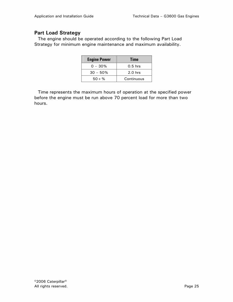
Part Load Strategy The engine should be operated according to the following Part Load
Strategy for minimum engine maintenance and maximum availability.
Engine Power Time 0 – 30% 0.5 hrs
30 – 50% 2.0 hrs
50+% Continuous
Time represents the maximum hours of operation at the specified power before the engine must be run above 70 percent load for more than two hours.

Technical Data – G3600 Gas Engines Application and Installation Guide
©2006 Caterpillar® Page 26 All rights reserved.
Sound Power Data (Mechanical, Exhaust & Air Inlet) Sound Power Data @ 900 rpm & 100% Load
Sound Level in Linear Decibels (db) “Octave Band Center Frequency” Sound Data
Overall Sound Level db(A)
16 Hz
32 Hz
63 Hz
125 Hz
250 Hz
500 Hz
1 kHz
2 kHz
4 kHz
8 kHz
G3606 Mechanical Sound
Exhaust Sound
Air Inlet Sound
117.4
132.2
127.7
—
—
—
—
125.7
106.7
110.8
128.6
114.8
115.4
125.7
113.4
114.3
119.1
112.9
113.5
117.1
110.8
112.0
120.8
111.4
108.0
125.1
118.0
110.6
129.4
123.4
103.3
127.9
123.6
G3608 Mechanical Sound
Exhaust Sound
Air Inlet Sound
123.3
139.5
127.9
98.7
108.3
90.1
103.6
114.7
89.5
114.4
122.2
93.6
112.5
124.0
<90
111.9
119.8
90.3
112.9
120.6
100.8
114.9
124.4
105.8
117.7
131.4
110.8
117.7
135.2
123.7
114.3
134.2
123.9
G3612 Mechanical Sound
Exhaust (Right) Sound
Exhaust (Left) Sound
Air Inlet (Left) Sound
124.0
141.0
124.9
124.2
95.4
97.8
93.4
<90
109.2
108.7
109.3
<90
118.8
122.0
122.1
<90
113.5
119.2
121.6
<90
112.9
118.7
114.3
<90
114.5
120.5
110.3
91.1
116.8
124.4
120.7
99.3
118.6
131.0
114.9
109.9
117.6
136.8
114.9
117.7
113.6
137.0
118.2
121.9
G3616 Mechanical Sound
Exhaust (Right) Sound
Exhaust (Left) Sound
Air Inlet (Left) Sound
128.1
144.6
129.0
129.3
—
—
—
—
111.1
117.3
117.5
<100
118.1
122.2
127.0
<100
124.9
128.6
126.3
99.9
121.4
124.4
121.1
102.9
119.4
125.3
121.1
102.9
119.2
129.0
123.3
108.0
121.5
134.7
123.5
114.8
123.3
139.8
120.9
126.2
118.1
139.0
119.9
125.5
Data determined by methods similar to ISO Standard DIS-8528-10. Accuracy Grade 3. All numbers reflect sound power. Air Inlet sound is without engine air cleaner(s).

Application and Installation Guide Technical Data – G3600 Gas Engines
©2006 Caterpillar® All rights reserved. Page 27
Sound Power Data @ 1000 rpm & 100% Load
Sound Level in Linear Decibels (db) “Octave Band Center Frequency” Sound Data
Overall Sound Level db(A)
16 Hz
32 Hz
63 Hz
125 Hz
250 Hz
500 Hz
1 kHz
2 kHz
4 kHz
8 kHz
G3606 Mechanical Sound
Exhaust Sound
Air Inlet Sound
118.4
136.6
127.0
—
—
—
—
119.2
104.4
—
130.3
113.8
119.6
127.2
115.8
116.9
122.2
115.0
115.5
119.9
112.9
113.6
123.1
112.0
108.6
128.8
117.4
109.0
133.3
122.6
99.8
131.4
123.0
G3608 Mechanical Sound
Exhaust Sound
Air Inlet Sound
125.4
143.4
129.9
103.8
102.7
<90
108.9
117.4
<90
113.8
119.7
<90
114.0
124.9
<90
112.8
121.3
97.3
114.9
123.3
101.5
116.0
126.7
106.2
119.8
135.2
109.9
120.3
139.3
126.6
115.9
138.2
125.2
G3612 Mechanical Sound
Exhaust (Right) Sound
Exhaust (Left) Sound
Air Inlet (Left) Sound
125.7
143.6
125.2
122.5
100.7
101.6
88.7
<90
108.0
107.9
104.1
<90
121.3
122.9
120.7
<90
125.7
121.0
119.7
<90
119.6
120.5
114.3
<90
119.6
122.5
111.7
93.4
118.9
127.5
120.5
<90
119.7
132.8
115.5
105.1
118.8
139.0
114.6
116.2
110.9
140.3
118.7
120.1
G3616 Mechanical Sound
Exhaust (Right) Sound
Exhaust (Left) Sound
Air Inlet (Left) Sound
128.1
144.6
129.0
129.3
—
—
—
—
111.1
117.3
117.5
<100
118.1
122.2
127.0
<100
124.9
128.6
126.3
99.9
121.4
124.4
121.1
102.9
119.4
125.3
121.1
102.9
119.2
129.0
123.3
108.0
121.5
134.7
123.5
114.8
123.3
139.8
120.9
126.2
118.1
139.0
119.9
125.5
Data determined by methods similar to ISO Standard DIS-8528-10. Accuracy Grade 3. All numbers reflect sound power. Air Inlet sound is without engine air cleaner(s).

Technical Data – G3600 Gas Engines Application and Installation Guide
©2006 Caterpillar® Page 28 All rights reserved.
Power Supply Requirements System Description Metric (English) G3606 G3608 G3612 G3616
Jacket Water Heater (Optional) kW (Btu/min)
18 (1024) 18 (1024) 30 (1706) 30 (1706)
Lube Oil Heater (Optional) kW (Btu/min)
9 (512) 9 (512) 9 (512) 9 (512)
Combination Jacket Water/Lube Oil Heater (Optional) kW (Btu/min)
18/9 (1024/512) 18/9 (1024/512) 18/9 (1024/512) 18/9 (1024/512)
Reference Materials The following information is provided as additional reference to subjects
discussed in this guide.
RENR5908 Systems Operation, Testing and Adjusting (G3600 Engines)
SEBU7563 Operation & Maintenance Manual (G3600 Engines)


LEBW5338-00 ©2006 Caterpillar® Printed in U.S.A. All rights reserved.