G3520C Trouble Shooting
364
RENR5979-03 March 2004 Troubleshooting G3520C and G3520E Engines GDB1-Up (Engine) GHC1-Up (Engine) GHE1-Up (Engine) GHM1-Up (Engine) GHR1-Up (Engine)
-
Upload
zaheer-abbas -
Category
Documents
-
view
2.227 -
download
80
Transcript of G3520C Trouble Shooting
RENR5979-03March 2004
TroubleshootingG3520C and G3520E EnginesGDB1-Up (Engine)GHC1-Up (Engine)GHE1-Up (Engine)GHM1-Up (Engine)GHR1-Up (Engine)
i01658146
Important Safety InformationMost accidents that involve product operation, maintenance and repair are caused by failure to observebasic safety rules or precautions. An accident can often be avoided by recognizing potentially hazardoussituations before an accident occurs. A person must be alert to potential hazards. This person should alsohave the necessary training, skills and tools to perform these functions properly.
Improper operation, lubrication, maintenance or repair of this product can be dangerous andcould result in injury or death.Do not operate or perform any lubrication, maintenance or repair on this product, until you haveread and understood the operation, lubrication, maintenance and repair information.Safety precautions and warnings are provided in this manual and on the product. If these hazard warningsare not heeded, bodily injury or death could occur to you or to other persons.
The hazards are identified by the “Safety Alert Symbol” and followed by a “Signal Word” such as“DANGER”, “WARNING” or “CAUTION”. The Safety Alert “WARNING” label is shown below.
The meaning of this safety alert symbol is as follows:
Attention! Become Alert! Your Safety is Involved.The message that appears under the warning explains the hazard and can be either written or pictoriallypresented.
Operations that may cause product damage are identified by “NOTICE” labels on the product and inthis publication.
Caterpillar cannot anticipate every possible circumstance that might involve a potential hazard.The warnings in this publication and on the product are, therefore, not all inclusive. If a tool,procedure, work method or operating technique that is not specifically recommended by Caterpillaris used, you must satisfy yourself that it is safe for you and for others. You should also ensure thatthe product will not be damaged or be made unsafe by the operation, lubrication, maintenance orrepair procedures that you choose.The information, specifications, and illustrations in this publication are on the basis of information thatwas available at the time that the publication was written. The specifications, torques, pressures,measurements, adjustments, illustrations, and other items can change at any time. These changes canaffect the service that is given to the product. Obtain the complete and most current information before youstart any job. Caterpillar dealers have the most current information available.
When replacement parts are required for thisproduct Caterpillar recommends using Caterpil-lar replacement parts or parts with equivalentspecifications including, but not limited to, phys-ical dimensions, type, strength and material.
Failure to heed this warning can lead to prema-ture failures, product damage, personal injury ordeath.
3Table of Contents
Table of Contents
Troubleshooting Section
Electronic TroubleshootingSystem Overview .................................................. 10Self-Diagnostics ..................................................... 11Location of Components ....................................... 12Electrical Connectors and Functions .................... 16Electronic Service Tools ........................................ 18Engine Monitoring System .................................... 20
Programming ParametersProgramming Parameters ..................................... 27Customer Passwords ............................................ 27Factory Passwords ............................................... 27Factory Passwords Worksheet ............................. 28Flash Programming .............................................. 29System Configuration Parameters ........................ 29Replacing the ECM ............................................... 30Replacing the ITSM .............................................. 32Troubleshooting Data Sheet ................................. 34
Troubleshooting without a Diagnostic CodeSymptoms ............................................................. 36Detonation ............................................................ 36Driven Equipment ................................................. 38ECM Will Not Accept Factory Passwords ............. 38Electronic Service Tool Will Not Communicate withECM (The Caterpillar Electronic Technician (ET)Will Not Communicate With an Electronic ControlModule (ECM) and/or the Integrated TemperatureSensing Module (ITSM)) ..................................... 38Engine Coolant Temperature (High) ..................... 39Engine Coolant Temperature (Low) ...................... 41Engine Cranks but Will Not Start .......................... 41Engine Misfires, Runs Rough or Is Unstable ........ 42Engine Oil Filter Differential Pressure ................... 44Engine Oil Pressure (Low) .................................... 44Engine Oil Temperature (High) ............................. 45Engine Overcrank ................................................. 46Engine Overload ................................................... 47Engine Overspeed ................................................ 47Engine Shutdown .................................................. 48Engine Shutdown (Unexpected) ........................... 48Engine Shutdown without a Diagnostic Code ....... 50Engine Starts but Stalls Immediately .................... 51Engine Timing Does Not Match ProgrammedTiming ................................................................. 51Engine Will Not Crank ........................................... 52Exhaust Port Temperature (High) ......................... 53Exhaust Port Temperature (Low) .......................... 54Fuel Energy Content ............................................. 55Fuel Metering Valve .............................................. 55Fuel Pressure ....................................................... 55Gas Fuel Differential Pressure (High) ................... 55Gas Fuel Differential Pressure (Low) .................... 56Gas Fuel Flow Rate (Low) .................................... 56Gas Temperature (High) ....................................... 57Generator Output Power Readings Do NotMatch .................................................................. 58
Inlet Air Temperature (High) .................................. 59Intermittent Engine Shutdown ............................... 60Jacket Water Inlet Pressure (High) ....................... 60Jacket Water Pressure (Low) ................................ 61Jacket Water to Engine Oil Differential Temperature(Low) ................................................................... 61System Voltage ..................................................... 62Turbocharger Turbine Temperature (High) ........... 62Turbocharger Turbine Temperature (Low) ............ 63
Troubleshooting with a Diagnostic CodeDiagnostic Codes .................................................. 65MID 033 - CID 0041 - FMI 03 8 Volt DC Supply shortto +batt ................................................................ 66MID 033 - CID 0041 - FMI 04 8 Volt DC Supply shortto ground ............................................................. 67MID 033 - CID 0168 - FMI 02 System Voltageintermittent/erratic ............................................... 67MID 033 - CID 0301 - FMI 05 Ignition TransformerPrimary #1 open circuit ....................................... 67MID 033 - CID 0301 - FMI 06 Ignition TransformerPrimary #1 short .................................................. 68MID 033 - CID 0303 - FMI 05 Ignition TransformerPrimary #3 open circuit ....................................... 68MID 033 - CID 0303 - FMI 06 Ignition TransformerPrimary #3 short .................................................. 68MID 033 - CID 0305 - FMI 05 Ignition TransformerPrimary #5 open circuit ....................................... 69MID 033 - CID 0305 - FMI 06 Ignition TransformerPrimary #5 short .................................................. 69MID 033 - CID 0307 - FMI 05 Ignition TransformerPrimary #7 open circuit ....................................... 69MID 033 - CID 0307 - FMI 06 Ignition TransformerPrimary #7 short .................................................. 70MID 033 - CID 0309 - FMI 05 Ignition TransformerPrimary #9 open circuit ....................................... 70MID 033 - CID 0309 - FMI 06 Ignition TransformerPrimary #9 short .................................................. 71MID 033 - CID 0311 - FMI 05 Ignition TransformerPrimary #11 open circuit ..................................... 71MID 033 - CID 0311 - FMI 06 Ignition TransformerPrimary #11 short ................................................ 71MID 033 - CID 0313 - FMI 05 Ignition TransformerPrimary #13 open circuit ..................................... 72MID 033 - CID 0313 - FMI 06 Ignition TransformerPrimary #13 short ................................................ 72MID 033 - CID 0315 - FMI 05 Ignition TransformerPrimary #15 open circuit ..................................... 72MID 033 - CID 0315 - FMI 06 Ignition TransformerPrimary #15 short ................................................ 73MID 033 - CID 0320 - FMI 03 Speed/Timing Sensorshort to +batt ....................................................... 73MID 033 - CID 0320 - FMI 08 Engine Speed/Timingsignal abnormal ................................................... 74MID 033 - CID 0401 - FMI 05 Ignition TransformerSecondary #1 open circuit .................................. 74MID 033 - CID 0401 - FMI 06 Ignition TransformerSecondary #1 short to ground ............................. 74MID 033 - CID 0403 - FMI 05 Ignition TransformerSecondary #3 open circuit .................................. 75MID 033 - CID 0403 - FMI 06 Ignition TransformerSecondary #3 short to ground ............................. 75
4Table of Contents
MID 033 - CID 0405 - FMI 05 Ignition TransformerSecondary #5 open circuit .................................. 75MID 033 - CID 0405 - FMI 06 Ignition TransformerSecondary #5 short to ground ............................. 76MID 033 - CID 0407 - FMI 05 Ignition TransformerSecondary #7 open circuit .................................. 76MID 033 - CID 0407 - FMI 06 Ignition TransformerSecondary #7 short to ground ............................. 77MID 033 - CID 0409 - FMI 05 Ignition TransformerSecondary #9 open circuit .................................. 77MID 033 - CID 0409 - FMI 06 Ignition TransformerSecondary #9 short to ground ............................. 77MID 033 - CID 0411 - FMI 05 Ignition TransformerSecondary #11 open circuit ................................. 78MID 033 - CID 0411 - FMI 06 Ignition TransformerSecondary #11 short to ground ........................... 78MID 033 - CID 0413 - FMI 05 Ignition TransformerSecondary #13 open circuit ................................ 79MID 033 - CID 0413 - FMI 06 Ignition TransformerSecondary #13 short to ground ........................... 79MID 033 - CID 0415 - FMI 05 Ignition TransformerSecondary #15 open circuit ................................ 79MID 033 - CID 0415 - FMI 06 Ignition TransformerSecondary #15 short to ground ........................... 80MID 033 - CID 0590 - FMI 09 Unable to communicatewith Engine ECM ................................................ 80MID 033 - CID 1501 - FMI 03 Cylinder #1 DetonationSensor open/short to +batt ................................. 81MID 033 - CID 1501 - FMI 04 Cylinder #1 DetonationSensor short to ground ....................................... 81MID 033 - CID 1505 - FMI 03 Cylinder #5 DetonationSensor open/short to +batt ................................. 81MID 033 - CID 1505 - FMI 04 Cylinder #5 DetonationSensor short to ground ....................................... 82MID 033 - CID 1509 - FMI 03 Cylinder #9 DetonationSensor open/short to +batt ................................. 82MID 033 - CID 1509 - FMI 04 Cylinder #9 DetonationSensor short to ground ....................................... 82MID 033 - CID 1513 - FMI 03 Cylinder #13 DetonationSensor open/short to +batt ................................. 83MID 033 - CID 1513 - FMI 04 Cylinder #13 DetonationSensor short to ground ....................................... 83MID 033 - CID 1517 - FMI 03 Cylinder #17 DetonationSensor open/short to +batt ................................. 83MID 033 - CID 1517 - FMI 04 Cylinder #17 DetonationSensor short to ground ....................................... 84MID 033 - CID 1748 - FMI 05 Ignition TransformerSecondary #17 open circuit ................................ 84MID 033 - CID 1748 - FMI 06 Ignition TransformerSecondary #17 short to ground ........................... 84MID 033 - CID 1750 - FMI 05 Ignition TransformerSecondary #19 open circuit ................................ 85MID 033 - CID 1750 - FMI 06 Ignition TransformerSecondary #19 short to ground ........................... 85MID 033 - CID 1752 - FMI 05 Ignition TransformerPrimary #17 open circuit ..................................... 85MID 033 - CID 1752 - FMI 06 Ignition TransformerPrimary #17 short to ground ............................... 86MID 033 - CID 1754 - FMI 05 Ignition TransformerPrimary #19 open circuit ..................................... 86
MID 033 - CID 1754 - FMI 06 Ignition TransformerPrimary #19 short to ground ............................... 87MID 036 - CID 0017 - FMI 05 Fuel Shutoff Valve opencircuit ................................................................... 87MID 036 - CID 0017 - FMI 06 Fuel Shutoff Valve shortto ground ............................................................. 87MID 036 - CID 0017 - FMI 12 Fuel Shutoff Valvemalfunction .......................................................... 88MID 036 - CID 0041 - FMI 03 8 Volt DC Supply shortto +batt ................................................................ 88MID 036 - CID 0041 - FMI 04 8 Volt DC Supply shortto ground ............................................................. 88MID 036 - CID 0100 - FMI 03 Engine Oil Pressureopen/short to +batt .............................................. 89MID 036 - CID 0100 - FMI 04 Engine Oil Pressureshort to ground .................................................... 89MID 036 - CID 0106 - FMI 03 Air Inlet PressureSensor short to +batt .......................................... 90MID 036 - CID 0106 - FMI 08 Air Inlet PressureSensor noisy signal ............................................. 90MID 036 - CID 0109 - FMI 03 Coolant Outlet Pressureopen/short to +batt .............................................. 90MID 036 - CID 0109 - FMI 08 Engine Coolant OutletPressure Sensor noisy signal ............................. 91MID 036 - CID 0110 - FMI 03 Engine CoolantTemperature open/short to +batt ......................... 91MID 036 - CID 0110 - FMI 04 Engine CoolantTemperature short to ground ............................... 91MID 036 - CID 0145 - FMI 03 12 Volt DC PowerSupply short to +batt ........................................... 92MID 036 - CID 0145 - FMI 04 12 Volt DC PowerSupply short to ground ........................................ 92MID 036 - CID 0168 - FMI 02 System Voltageintermittent/erratic ............................................... 92MID 036 - CID 0172 - FMI 03 Intake Manifold AirTemp open/short to +batt .................................... 93MID 036 - CID 0172 - FMI 04 Intake Manifold AirTemp short to ground .......................................... 93MID 036 - CID 0175 - FMI 03 Engine Oil Temperatureopen/short to +batt .............................................. 93MID 036 - CID 0175 - FMI 04 Engine Oil Temperatureshort to ground .................................................... 94MID 036 - CID 0261 - FMI 13 Engine Timingcalibration required ............................................. 94MID 036 - CID 0262 - FMI 03 5 Volt Sensor DCPower Supply short to +batt ................................ 95MID 036 - CID 0262 - FMI 04 5 Volt Sensor DCPower Supply short to ground ............................. 95MID 036 - CID 0302 - FMI 05 Ignition TransformerPrimary #2 open circuit ....................................... 96MID 036 - CID 0302 - FMI 06 Ignition TransformerPrimary #2 short .................................................. 96MID 036 - CID 0304 - FMI 05 Ignition TransformerPrimary #4 open circuit ....................................... 96MID 036 - CID 0304 - FMI 06 Ignition TransformerPrimary #4 short .................................................. 97MID 036 - CID 0306 - FMI 05 Ignition TransformerPrimary #6 open circuit ....................................... 97MID 036 - CID 0306 - FMI 06 Ignition TransformerPrimary #6 short .................................................. 97
5Table of Contents
MID 036 - CID 0308 - FMI 05 Ignition TransformerPrimary #8 open circuit ....................................... 98MID 036 - CID 0308 - FMI 06 Ignition TransformerPrimary #8 short .................................................. 98MID 036 - CID 0310 - FMI 05 Ignition TransformerPrimary #10 open circuit ..................................... 98MID 036 - CID 0310 - FMI 06 Ignition TransformerPrimary #10 short ................................................ 99MID 036 - CID 0312 - FMI 05 Ignition TransformerPrimary #12 open circuit ..................................... 99MID 036 - CID 0312 - FMI 06 Ignition TransformerPrimary #12 short .............................................. 100MID 036 - CID 0314 - FMI 05 Ignition TransformerPrimary #14 open circuit ................................... 100MID 036 - CID 0314 - FMI 06 Ignition TransformerPrimary #14 short .............................................. 100MID 036 - CID 0316 - FMI 05 Ignition TransformerPrimary #16 open circuit ................................... 101MID 036 - CID 0316 - FMI 06 Ignition TransformerPrimary #16 short .............................................. 101MID 036 - CID 0320 - FMI 03 Speed/Timing Sensorshort to +batt ..................................................... 101MID 036 - CID 0320 - FMI 08 Engine Speed/Timingsignal abnormal ................................................. 102MID 036 - CID 0323 - FMI 03 Shutdown Lamp shortto +batt .............................................................. 102MID 036 - CID 0324 - FMI 03 Warning Lamp short to+batt .................................................................. 102MID 036 - CID 0336 - FMI 02 Incorrect ECS Switchinputs ................................................................ 103MID 036 - CID 0402 - FMI 05 Ignition TransformerSecondary #2 open circuit ................................ 103MID 036 - CID 0402 - FMI 06 Ignition TransformerSecondary #2 short to ground ........................... 103MID 036 - CID 0404 - FMI 05 Ignition TransformerSecondary #4 open circuit ................................ 104MID 036 - CID 0404 - FMI 06 Ignition TransformerSecondary #4 short to ground ........................... 104MID 036 - CID 0406 - FMI 05 Ignition TransformerSecondary #6 open circuit ................................ 105MID 036 - CID 0406 - FMI 06 Ignition TransformerSecondary #6 short to ground ........................... 105MID 036 - CID 0408 - FMI 05 Ignition TransformerSecondary #8 open circuit ................................ 105MID 036 - CID 0408 - FMI 06 Ignition TransformerSecondary #8 short to ground ........................... 106MID 036 - CID 0410 - FMI 05 Ignition TransformerSecondary #10 open circuit .............................. 106MID 036 - CID 0410 - FMI 06 Ignition TransformerSecondary #10 short to ground ......................... 107MID 036 - CID 0412 - FMI 05 Ignition TransformerSecondary #12 open circuit .............................. 107MID 036 - CID 0412 - FMI 06 Ignition TransformerSecondary #12 short to ground ......................... 107MID 036 - CID 0414 - FMI 05 Ignition TransformerSecondary #14 open circuit .............................. 108MID 036 - CID 0414 - FMI 06 Ignition TransformerSecondary #14 short to ground ......................... 108MID 036 - CID 0416 - FMI 05 Ignition TransformerSecondary #16 open circuit .............................. 108MID 036 - CID 0416 - FMI 06 Ignition TransformerSecondary #16 short to ground ......................... 109
MID 036 - CID 0443 - FMI 03 Crank Terminate Relayshort to +batt ..................................................... 109MID 036 - CID 0444 - FMI 05 Start Relay opencircuit .................................................................. 110MID 036 - CID 0444 - FMI 06 Start Relay short toground ................................................................ 110MID 036 - CID 0445 - FMI 03 Run Relay short to+batt ................................................................... 110MID 036 - CID 0524 - FMI 03 Desired Engine SpeedSensor short to +batt ......................................... 111MID 036 - CID 0524 - FMI 04 Desired Engine SpeedSensor short to ground ...................................... 111MID 036 - CID 0542 - FMI 03 Unfiltered Engine OilPressure open/short to +batt ............................. 111MID 036 - CID 0542 - FMI 04 Unfiltered Engine OilPressure short to ground ................................... 112MID 036 - CID 1042 - FMI 09 Unable to communicatewith ITSM ........................................................... 112MID 036 - CID 1440 - FMI 09 Unable to communicatewith Throttle Actuator Drv .................................. 113MID 036 - CID 1446 - FMI 05 Fuel Metering Moduleopen circuit ......................................................... 113MID 036 - CID 1446 - FMI 09 Unable to communicatewith Fuel Metering Module ................................. 113MID 036 - CID 1446 - FMI 12 Fuel Metering Modulemalfunction ......................................................... 114MID 036 - CID 1446 - FMI 13 Fuel Metering Modulecalibration required ............................................ 114MID 036 - CID 1447 - FMI 12 Fuel Metering SensorModule malfunction ............................................ 114MID 036 - CID 1502 - FMI 03 Cylinder #2 DetonationSensor open/short to +batt ................................ 114MID 036 - CID 1502 - FMI 04 Cylinder #2 DetonationSensor short to ground ...................................... 115MID 036 - CID 1506 - FMI 03 Cylinder #6 DetonationSensor open/short to +batt ................................ 115MID 036 - CID 1506 - FMI 04 Cylinder #6 DetonationSensor short to ground ...................................... 115MID 036 - CID 1510 - FMI 03 Cylinder #10 DetonationSensor open/short to +batt ................................ 116MID 036 - CID 1510 - FMI 04 Cylinder #10 DetonationSensor short to ground ...................................... 116MID 036 - CID 1514 - FMI 03 Cylinder #14 DetonationSensor open/short to +batt ................................ 116MID 036 - CID 1514 - FMI 04 Cylinder #14 DetonationSensor short to ground ...................................... 117MID 036 - CID 1518 - FMI 03 Cylinder #18 DetonationSensor open/short to +batt ................................ 117MID 036 - CID 1518 - FMI 04 Cylinder #18 DetonationSensor short to ground ...................................... 117MID 036 - CID 1636 - FMI 09 Loss of Communicationwith Engine #2 (Slave) ....................................... 118MID 036 - CID 1719 - FMI 03 Generator OutputPower Sensor open/short to +batt ..................... 118MID 036 - CID 1719 - FMI 04 Generator OutputPower Sensor short to ground ........................... 118MID 036 - CID 1719 - FMI 12 Generator OutputPower Sensor malfunction ................................. 119MID 036 - CID 1720 - FMI 09 TurbochargerCompressor Bypass Valve Actuator notcommunicating on link ....................................... 119MID 036 - CID 1749 - FMI 05 Ignition TransformerSecondary #18 open circuit ............................... 119
6Table of Contents
MID 036 - CID 1749 - FMI 06 Ignition TransformerSecondary #18 short to ground ......................... 120MID 036 - CID 1751 - FMI 05 Ignition TransformerSecondary #20 open circuit .............................. 120MID 036 - CID 1751 - FMI 06 Ignition TransformerSecondary #20 short to ground ......................... 120MID 036 - CID 1753 - FMI 05 Ignition TransformerPrimary #18 open circuit ................................... 121MID 036 - CID 1753 - FMI 06 Ignition TransformerPrimary #18 short to ground ............................. 121MID 036 - CID 1755 - FMI 05 Ignition TransformerPrimary #20 open circuit ................................... 121MID 036 - CID 1755 - FMI 06 Ignition TransformerPrimary #20 short to ground ............................. 122MID 111 - CID 0591 - FMI 12 EEPROM checksumfault or ECM not programmed ........................... 122MID 111 - CID 1489 - FMI 03 Left Turbo Turbine OutTemp Sens short to +batt .................................. 122MID 111 - CID 1489 - FMI 04 Left Turbo Turbine OutTemp Sens short to ground ............................... 123MID 111 - CID 1489 - FMI 05 Left Turbo Turbine OutTemp Sens open circuit ..................................... 123MID 111 - CID 1490 - FMI 03 Rt Turbo Turbine OutTemp Sens short to +batt .................................. 123MID 111 - CID 1490 - FMI 04 Rt Turbo Turbine OutTemp Sens short to ground ............................... 124MID 111 - CID 1490 - FMI 05 Rt Turbo Turbine OutTemp Sens open circuit ..................................... 124MID 111 - CID 1491 - FMI 03 Rt Turbo Turbine InTemp Sens short to +batt .................................. 124MID 111 - CID 1491 - FMI 04 Rt Turbo Turbine InTemp Sens short to ground ............................... 125MID 111 - CID 1491 - FMI 05 Rt Turbo Turbine InTemp Sens open circuit ..................................... 125MID 111 - CID 1492 - FMI 03 Left Turbo Turbine InTemp Sens short to +batt .................................. 125MID 111 - CID 1492 - FMI 04 Left Turbo Turbine InTemp Sens short to ground ............................... 126MID 111 - CID 1492 - FMI 05 Left Turbo Turbine InTemp Sens open circuit ..................................... 126MID 111 - CID 1531 - FMI 03 Cyl #1 Exhaust PortTemp Sensor short to +batt ............................... 126MID 111 - CID 1531 - FMI 04 Cyl #1 Exhaust PortTemp Sensor short to ground ............................ 127MID 111 - CID 1531 - FMI 05 Cyl #1 Exhaust PortTemp Sensor open circuit ................................. 127MID 111 - CID 1532 - FMI 03 Cyl #2 Exhaust PortTemp Sensor short to +batt ............................... 127MID 111 - CID 1532 - FMI 04 Cyl #2 Exhaust PortTemp Sensor short to ground ............................ 128MID 111 - CID 1532 - FMI 05 Cyl #2 Exhaust PortTemp Sensor open circuit ................................. 128MID 111 - CID 1533 - FMI 03 Cyl #3 Exhaust PortTemp Sensor short to +batt ............................... 129MID 111 - CID 1533 - FMI 04 Cyl #3 Exhaust PortTemp Sensor short to ground ............................ 129MID 111 - CID 1533 - FMI 05 Cyl #3 Exhaust PortTemp Sensor open circuit ................................. 129MID 111 - CID 1534 - FMI 03 Cyl #4 Exhaust PortTemp Sensor short to +batt ............................... 130
MID 111 - CID 1534 - FMI 04 Cyl #4 Exhaust PortTemp Sensor short to ground ............................ 130MID 111 - CID 1534 - FMI 05 Cyl #4 Exhaust PortTemp Sensor open circuit ................................. 130MID 111 - CID 1535 - FMI 03 Cyl #5 Exhaust PortTemp Sensor short to +batt ............................... 131MID 111 - CID 1535 - FMI 04 Cyl #5 Exhaust PortTemp Sensor short to ground ............................ 131MID 111 - CID 1535 - FMI 05 Cyl #5 Exhaust PortTemp Sensor open circuit ................................. 132MID 111 - CID 1536 - FMI 03 Cyl #6 Exhaust PortTemp Sensor short to +batt ............................... 132MID 111 - CID 1536 - FMI 04 Cyl #6 Exhaust PortTemp Sensor short to ground ............................ 132MID 111 - CID 1536 - FMI 05 Cyl #6 Exhaust PortTemp Sensor open circuit ................................. 133MID 111 - CID 1537 - FMI 03 Cyl #7 Exhaust PortTemp Sensor short to +batt ............................... 133MID 111 - CID 1537 - FMI 04 Cyl #7 Exhaust PortTemp Sensor short to ground ............................ 133MID 111 - CID 1537 - FMI 05 Cyl #7 Exhaust PortTemp Sensor open circuit ................................. 134MID 111 - CID 1538 - FMI 03 Cyl #8 Exhaust PortTemp Sensor short to +batt ............................... 134MID 111 - CID 1538 - FMI 04 Cyl #8 Exhaust PortTemp Sensor short to ground ............................ 135MID 111 - CID 1538 - FMI 05 Cyl #8 Exhaust PortTemp Sensor open circuit ................................. 135MID 111 - CID 1539 - FMI 03 Cyl #9 Exhaust PortTemp Sensor short to +batt ............................... 135MID 111 - CID 1539 - FMI 04 Cyl #9 Exhaust PortTemp Sensor short to ground ............................ 136MID 111 - CID 1539 - FMI 05 Cyl #9 Exhaust PortTemp Sensor open circuit ................................. 136MID 111 - CID 1540 - FMI 03 Cyl #10 Exhaust PortTemp Sensor short to +batt ............................... 136MID 111 - CID 1540 - FMI 04 Cyl #10 Exhaust PortTemp Sensor short to ground ............................ 137MID 111 - CID 1540 - FMI 05 Cyl #10 Exhaust PortTemp Sensor open circuit ................................. 137MID 111 - CID 1541 - FMI 03 Cyl #11 Exhaust PortTemp Sensor short to +batt ............................... 138MID 111 - CID 1541 - FMI 04 Cyl #11 Exhaust PortTemp Sensor short to ground ............................ 138MID 111 - CID 1541 - FMI 05 Cyl #11 Exhaust PortTemp Sensor open circuit ................................. 138MID 111 - CID 1542 - FMI 03 Cyl #12 Exhaust PortTemp Sensor short to +batt ............................... 139MID 111 - CID 1542 - FMI 04 Cyl #12 Exhaust PortTemp Sensor short to ground ............................ 139MID 111 - CID 1542 - FMI 05 Cyl #12 Exhaust PortTemp Sensor open circuit ................................. 139MID 111 - CID 1543 - FMI 03 Cyl #13 Exhaust PortTemp Sensor short to +batt ............................... 140MID 111 - CID 1543 - FMI 04 Cyl #13 Exhaust PortTemp Sensor short to ground ............................ 140MID 111 - CID 1543 - FMI 05 Cyl #13 Exhaust PortTemp Sensor open circuit ................................. 141MID 111 - CID 1544 - FMI 03 Cyl #14 Exhaust PortTemp Sensor short to +batt ............................... 141
7Table of Contents
MID 111 - CID 1544 - FMI 04 Cyl #14 Exhaust PortTemp Sensor short to ground ............................ 141MID 111 - CID 1544 - FMI 05 Cyl #14 Exhaust PortTemp Sensor open circuit ................................. 142MID 111 - CID 1545 - FMI 03 Cyl #15 Exhaust PortTemp Sensor short to +batt ............................... 142MID 111 - CID 1545 - FMI 04 Cyl #15 Exhaust PortTemp Sensor short to ground ............................ 142MID 111 - CID 1545 - FMI 05 Cyl #15 Exhaust PortTemp Sensor open circuit ................................. 143MID 111 - CID 1546 - FMI 03 Cyl #16 Exhaust PortTemp Sensor short to +batt ............................... 143MID 111 - CID 1546 - FMI 04 Cyl #16 Exhaust PortTemp Sensor short to ground ............................ 144MID 111 - CID 1546 - FMI 05 Cyl #16 Exhaust PortTemp Sensor open circuit ................................. 144MID 111 - CID 1547 - FMI 03 Cyl #17 Exhaust PortTemp Sensor short to +batt ............................... 144MID 111 - CID 1547 - FMI 04 Cyl #17 Exhaust PortTemp Sensor short to ground ............................ 145MID 111 - CID 1547 - FMI 05 Cyl #17 Exhaust PortTemp Sensor open circuit ................................. 145MID 111 - CID 1548 - FMI 03 Cyl #18 Exhaust PortTemp Sensor short to +batt ............................... 145MID 111 - CID 1548 - FMI 04 Cyl #18 Exhaust PortTemp Sensor short to ground ............................ 146MID 111 - CID 1548 - FMI 05 Cyl #18 Exhaust PortTemp Sensor open circuit ................................. 146MID 111 - CID 1549 - FMI 03 Cyl #19 Exhaust PortTemp Sensor short to +batt ............................... 147MID 111 - CID 1549 - FMI 04 Cyl #19 Exhaust PortTemp Sensor short to ground ............................ 147MID 111 - CID 1549 - FMI 05 Cyl #19 Exhaust PortTemp Sensor open circuit ................................. 147MID 111 - CID 1550 - FMI 03 Cyl #20 Exhaust PortTemp Sensor short to +batt ............................... 148MID 111 - CID 1550 - FMI 04 Cyl #20 Exhaust PortTemp Sensor short to ground ............................ 148MID 111 - CID 1550 - FMI 05 Cyl #20 Exhaust PortTemp Sensor open circuit ................................. 148
Troubleshooting with an Event CodeEvent Codes ...................................................... 150E004 Engine Overspeed Shutdown .................... 152E016 High Engine Coolant TemperatureShutdown .......................................................... 152E017 High Engine Coolant TemperatureWarning ............................................................. 153E019 High Engine Oil Temperature Shutdown ... 153E020 High Engine Oil Temperature Warning ...... 153E026 High Inlet Air Temperature Shutdown ........ 153E027 High Inlet Air Temperature Warning .......... 154E038 Low Engine Coolant TemperatureWarning ............................................................. 154E040 Low Engine Oil Pressure Shutdown .......... 154E042 Low System Voltage Shutdown ................. 155E043 Low System Voltage Warning .................... 155E050 High System Voltage Warning ................... 155E053 Low Fuel Pressure Warning ...................... 155E096 High Fuel Pressure .................................... 156E100 Low Engine Oil Pressure Warning ............. 156E127 Engine Oil Filter Diff Pressure LowWarning ............................................................. 156
E128 Engine Oil Filter Diff Pressure LowShutdown .......................................................... 156E129 Engine Oil Filter Diff Pressure HighWarning ............................................................. 157E130 Engine Oil Filter Diff Pressure HighShutdown .......................................................... 157E135 Low Jacket Water Pressure Shutdown ...... 157E223 High Gas Temperature .............................. 158E224 High Jacket Water Inlet Pressure .............. 158E225 Engine Overcrank ...................................... 158E226 Driven Equipment Not Ready .................... 158E229 Fuel Energy Content Setting Low .............. 159E230 Fuel Energy Content Setting High ............. 159E231 Fuel Quality Out of Range ......................... 159E243 High Left Turbo Turbine OutletTemperature ...................................................... 159E244 High Right Turbo Turbine OutletTemperature ...................................................... 160E245 High Right Turbo Turbine InletTemperature ...................................................... 160E246 High Left Turbo Turbine InletTemperature ...................................................... 161E264 Emergency Stop Activated ........................ 161E268 Unexpected Engine Shutdown .................. 161E269 Customer Shutdown Requested ............... 161E270 Driven Equipment Shutdown Requested .. 162E337 High Engine Oil to Engine Coolant DiffTemp ................................................................. 162E401 Cylinder #1 Detonation .............................. 163E402 Cylinder #2 Detonation .............................. 163E403 Cylinder #3 Detonation .............................. 163E404 Cylinder #4 Detonation .............................. 163E405 Cylinder #5 Detonation .............................. 164E406 Cylinder #6 Detonation .............................. 164E407 Cylinder #7 Detonation .............................. 164E408 Cylinder #8 Detonation .............................. 164E409 Cylinder #9 Detonation .............................. 165E410 Cylinder #10 Detonation ............................ 165E411 Cylinder #11 Detonation ............................ 165E412 Cylinder #12 Detonation ............................ 165E413 Cylinder #13 Detonation ............................ 166E414 Cylinder #14 Detonation ............................ 166E415 Cylinder #15 Detonation ............................ 166E416 Cylinder #16 Detonation ............................ 166E417 Cylinder #17 Detonation ............................ 167E418 Cylinder #18 Detonation ............................ 167E419 Cylinder #19 Detonation ............................ 167E420 Cylinder #20 Detonation ............................ 167E421 Cylinder #1 Detonation Shutdown ............. 168E422 Cylinder #2 Detonation Shutdown ............. 168E423 Cylinder #3 Detonation Shutdown ............. 168E424 Cylinder #4 Detonation Shutdown ............. 168E425 Cylinder #5 Detonation Shutdown ............. 169E426 Cylinder #6 Detonation Shutdown ............. 169E427 Cylinder #7 Detonation Shutdown ............. 169E428 Cylinder #8 Detonation Shutdown ............. 169E429 Cylinder #9 Detonation Shutdown ............. 170E430 Cylinder #10 Detonation Shutdown ........... 170E431 Cylinder #11 Detonation Shutdown ........... 170E432 Cylinder #12 Detonation Shutdown ........... 171E433 Cylinder #13 Detonation Shutdown ........... 171E434 Cylinder #14 Detonation Shutdown ........... 171E435 Cylinder #15 Detonation Shutdown ........... 171
8Table of Contents
E436 Cylinder #16 Detonation Shutdown ........... 172E437 Cylinder #17 Detonation Shutdown ........... 172E438 Cylinder #18 Detonation Shutdown ........... 172E439 Cylinder #19 Detonation Shutdown ........... 173E440 Cylinder #20 Detonation Shutdown ........... 173E801 Cylinder #1 High Exhaust Port Temp ........ 173E802 Cylinder #2 High Exhaust Port Temp ........ 173E803 Cylinder #3 High Exhaust Port Temp ........ 174E804 Cylinder #4 High Exhaust Port Temp ........ 174E805 Cylinder #5 High Exhaust Port Temp ........ 175E806 Cylinder #6 High Exhaust Port Temp ........ 175E807 Cylinder #7 High Exhaust Port Temp ........ 175E808 Cylinder #8 High Exhaust Port Temp ........ 176E809 Cylinder #9 High Exhaust Port Temp ........ 176E810 Cylinder #10 High Exhaust Port Temp ...... 177E811 Cylinder #11 High Exhaust Port Temp ....... 177E812 Cylinder #12 High Exhaust Port Temp ...... 177E813 Cylinder #13 High Exhaust Port Temp ...... 178E814 Cylinder #14 High Exhaust Port Temp ...... 178E815 Cylinder #15 High Exhaust Port Temp ...... 179E816 Cylinder #16 High Exhaust Port Temp ...... 179E817 Cylinder #17 High Exhaust Port Temp ...... 179E818 Cylinder #18 High Exhaust Port Temp ...... 180E819 Cylinder #19 High Exhaust Port Temp ...... 180E820 Cylinder #20 High Exhaust Port Temp ...... 180E821 Cyl #1 Exhaust Port Temp Deviating High .. 181E822 Cyl #2 Exhaust Port Temp Deviating High .. 181E823 Cyl #3 Exhaust Port Temp Deviating High .. 182E824 Cyl #4 Exhaust Port Temp Deviating High .. 182E825 Cyl #5 Exhaust Port Temp Deviating High .. 183E826 Cyl #6 Exhaust Port Temp Deviating High .. 183E827 Cyl #7 Exhaust Port Temp Deviating High .. 183E828 Cyl #8 Exhaust Port Temp Deviating High .. 184E829 Cyl #9 Exhaust Port Temp Deviating High .. 184E830 Cyl #10 Exhaust Port Temp DeviatingHigh ................................................................... 185E831 Cyl #11 Exhaust Port Temp DeviatingHigh ................................................................... 185E832 Cyl #12 Exhaust Port Temp DeviatingHigh ................................................................... 185E833 Cyl #13 Exhaust Port Temp DeviatingHigh ................................................................... 186E834 Cyl #14 Exhaust Port Temp DeviatingHigh ................................................................... 186E835 Cyl #15 Exhaust Port Temp DeviatingHigh ................................................................... 187E836 Cyl #16 Exhaust Port Temp DeviatingHigh ................................................................... 187E837 Cyl #17 Exhaust Port Temp DeviatingHigh ................................................................... 187E838 Cyl #18 Exhaust Port Temp DeviatingHigh ................................................................... 188E839 Cyl #19 Exhaust Port Temp DeviatingHigh ................................................................... 188E840 Cyl #20 Exhaust Port Temp DeviatingHigh ................................................................... 189E841 Cyl #1 Exhaust Port Temp Deviating Low .. 189E842 Cyl #2 Exhaust Port Temp Deviating Low .. 189E843 Cyl #3 Exhaust Port Temp Deviating Low .. 190E844 Cyl #4 Exhaust Port Temp Deviating Low .. 190E845 Cyl #5 Exhaust Port Temp Deviating Low .. 191
E846 Cyl #6 Exhaust Port Temp Deviating Low .. 191E847 Cyl #7 Exhaust Port Temp Deviating Low .. 191E848 Cyl #8 Exhaust Port Temp Deviating Low .. 192E849 Cyl #9 Exhaust Port Temp Deviating Low .. 192E850 Cyl #10 Exhaust Port Temp DeviatingLow ................................................................... 193E851 Cyl #11 Exhaust Port Temp DeviatingLow ................................................................... 193E852 Cyl #12 Exhaust Port Temp DeviatingLow ................................................................... 193E853 Cyl #13 Exhaust Port Temp DeviatingLow ................................................................... 194E854 Cyl #14 Exhaust Port Temp DeviatingLow ................................................................... 194E855 Cyl #15 Exhaust Port Temp DeviatingLow ................................................................... 195E856 Cyl #16 Exhaust Port Temp DeviatingLow ................................................................... 195E857 Cyl #17 Exhaust Port Temp DeviatingLow ................................................................... 195E858 Cyl #18 Exhaust Port Temp DeviatingLow ................................................................... 196E859 Cyl #19 Exhaust Port Temp DeviatingLow ................................................................... 196E860 Cyl #20 Exhaust Port Temp DeviatingLow ................................................................... 197E864 Low Gas Fuel Differential Pressure ........... 197E865 High Gas Fuel Differential Pressure .......... 197E866 Low Gas Fuel Flow Rate ........................... 197E867 Improper Gas Flow Control ValveResponse .......................................................... 198E868 Gas Flow Control Valve Malfunction ......... 198
Diagnostic Functional Tests+5V Sensor Voltage Supply ................................ 199+8V Sensor Voltage Supply ................................ 206Analog Sensor Signal ......................................... 214CAT Data Link ..................................................... 223Compressor Bypass ........................................... 229Desired Speed Input (4 - 20 mA) ........................ 235Detonation Sensors ............................................ 239ECM Output Circuit (Fuel Control) ...................... 248ECM Output Circuit (Starting Motor) ................... 257ECM Status Indicator Output .............................. 269Electrical Power Supply ...................................... 275Engine Speed/Timing Sensor ............................. 282Fuel Metering Valve ............................................ 289Generator Output Power Sensor ........................ 298Ignition Transformers Primary Circuit ................. 305Ignition Transformers Secondary Circuit and SparkPlugs ................................................................. 316Inspecting Electrical Connectors ........................ 322Integrated Temperature Sensing Module(ITSM) ............................................................... 327PWM Sensor ....................................................... 335Throttle Actuator ................................................. 342
Calibration ProceduresEngine Speed/Timing Sensor - Calibrate ............ 349Generator Output Power Sensor - Calibrate ....... 351

9Table of Contents
Index Section
Index ................................................................... 355
10Troubleshooting Section
Troubleshooting Section
Electronic Troubleshootingi02072648
System OverviewSMCS Code: 1900
IntroductionTwo Electronic Control Modules (ECM) are used tocontrol the engine. One module is the master ECMand the other module is the slave ECM. Each moduleis an environmentally sealed unit that is mounted in aterminal box on the engine.
The master ECM controls most of the functions ofthe engine. The master ECM monitors various inputsfrom sensors in order to activate relays, solenoids,etc at the appropriate levels. The master ECMsupports the following five primary functions:
• Engine speed governing
• Air/fuel ratio control
• Start/stop sequencing
• Engine monitoring and protection
• Control of the ignition and detonation of the leftcylinder bank
The slave ECM primarily supports the control ofignition and of detonation of the right cylinder bank.
Engine Speed GoverningThe master ECM maintains the desired enginespeed by controlling the actuator for the throttle. Theactuator is located at the inlet to the aftercooler.The actuator is electrically controlled and electricallyactuated.
The master ECM issues a throttle command thatrepresents a percent of the level of electricalcurrent. The output can be viewed on the CaterpillarElectronic Technician (ET).
Desired engine speed is determined by the statusof the idle/rated switch, the desired speed input(analog voltage or 4 to 20 mA), and parameterssuch as maximum engine high idle speed thatare programmed into the software. Actual enginespeed is detected via a signal from the speed/timingsensor. Parameters such as governor gain can beprogrammed with Cat ET.
Air/Fuel Ratio ControlThe master ECM provides control of the air/fuelmixture for performance and for efficiency at lowemission levels. The system consists of an electronicfuel metering valve, output drivers in the masterECM, and maps in the master ECM. The controlcompensates for changes in the BTU of the fuel inorder to maintain desired emission levels.
The following steps describe the basic operation:
1. The master ECM determines the desired flowrates for the air and for the fuel. The flow rates aredetermined by these factors:
• Desired engine speed
• Actual engine speed
• Calculated engine load
2. The command for the flow of the fuel is sent tothe electronic fuel metering valve via the CANdata link.
This process is repeated continuously during engineoperation.
Start/Stop SequencingThe master ECM contains the logic and the outputsfor control of starting and of shutdown. The customerprogrammable logic responds to signals from thefollowing components: engine control, emergencystop switch, remote start switch, data link, and otherinputs.
When the programmable logic determines that itis necessary to crank the engine, the master ECMsupplies +Battery voltage to the relay for the startingmotor. The master ECM removes the voltage whenthe programmable crank terminate speed is reachedor when a programmable cycle crank time hasexpired.
11Troubleshooting Section
The engine must be equipped with an energize-to-runtype of gas shutoff valve (GSOV). The source ofthe voltage to the GSOV depends on the engine’sconfiguration. The GSOV may be energized by thecustomer’s equipment or by the engine’s controlsystem.
If the engine’s control system controls the GSOV, themaster ECM supplies +Battery voltage to the GSOVwhenever the programmable logic determines thatfuel is required to operate the engine.
For more information on programmable parameters,see Troubleshooting, “Programming Parameters”.
Engine Monitoring and ProtectionThe master ECM monitors both the engine operationand the electronic system.
Problems with engine operation such as low oilpressure produce an event code. The master ECMcan issue a warning or a shutdown. This depends onthe severity of the condition. For more information,see Troubleshooting, “Troubleshooting With An EventCode”.
Problems with the electronic system such as anopen circuit produce a diagnostic code. For moreinformation, see Troubleshooting, “TroubleshootingWith A Diagnostic Code”.
Ignition ControlEach ECM provides variable ignition timing that issensitive to detonation.
Each cylinder has an ignition transformer that islocated under the valve cover for the cylinder.To initiate combustion, an ECM sends a pulse ofapproximately 100 volts to the primary coil of anignition transformer at the appropriate time and forthe appropriate duration. The transformer steps upthe voltage in order to create a spark across thespark plug electrode.
Detonation sensors monitor the engine forexcessive detonation. The G3520C Engine hasten detonation sensors. Each sensor monitors twoadjacent cylinders. The sensors generate data onvibration that is processed by each ECM in order todetermine detonation levels. If detonation reaches anunacceptable level, the appropriate ECM retards theignition timing of the affected cylinder or cylinders. Ifretarding the timing does not limit detonation to anacceptable level, the master ECM shuts down theengine.
The master ECM and the slave ECM provideextensive diagnostics for the ignition system. Themaster ECM also provides a switch for ignition timingin order to allow operation with alternate fuels suchas propane that require a timing offset.
i01804722
Self-DiagnosticsSMCS Code: 1901
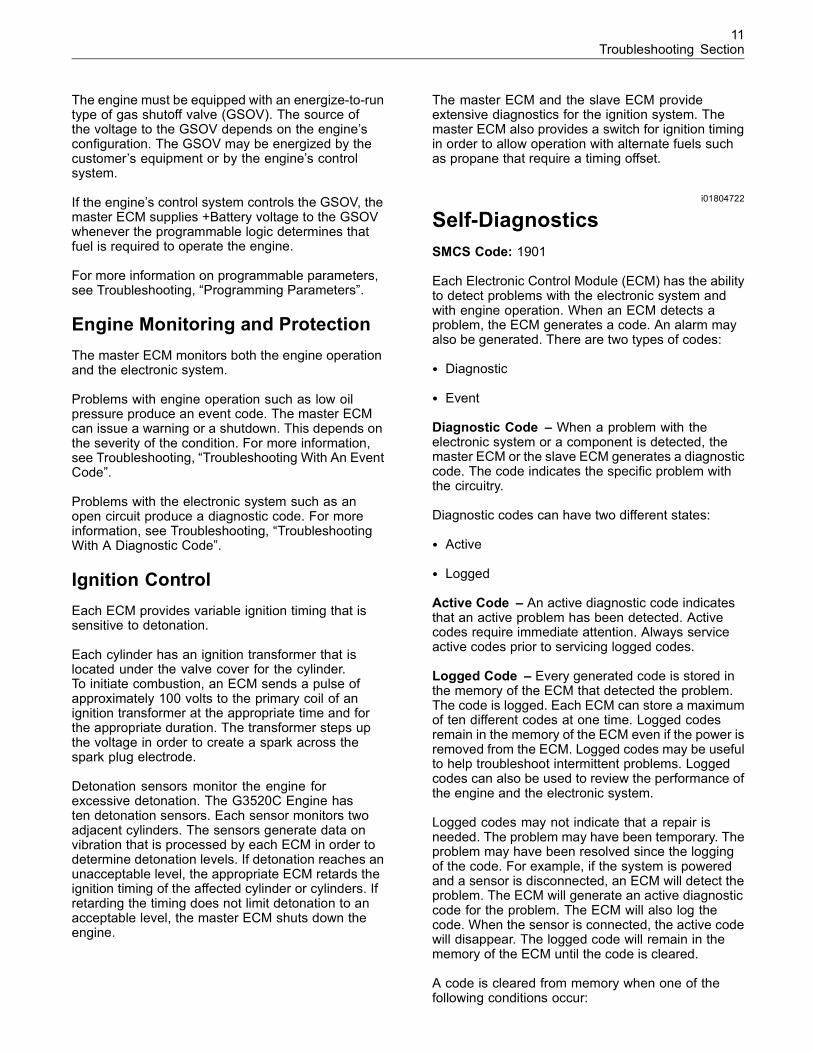
Each Electronic Control Module (ECM) has the abilityto detect problems with the electronic system andwith engine operation. When an ECM detects aproblem, the ECM generates a code. An alarm mayalso be generated. There are two types of codes:
• Diagnostic
• Event
Diagnostic Code – When a problem with theelectronic system or a component is detected, themaster ECM or the slave ECM generates a diagnosticcode. The code indicates the specific problem withthe circuitry.
Diagnostic codes can have two different states:
• Active
• Logged
Active Code – An active diagnostic code indicatesthat an active problem has been detected. Activecodes require immediate attention. Always serviceactive codes prior to servicing logged codes.
Logged Code – Every generated code is stored inthe memory of the ECM that detected the problem.The code is logged. Each ECM can store a maximumof ten different codes at one time. Logged codesremain in the memory of the ECM even if the power isremoved from the ECM. Logged codes may be usefulto help troubleshoot intermittent problems. Loggedcodes can also be used to review the performance ofthe engine and the electronic system.
Logged codes may not indicate that a repair isneeded. The problem may have been temporary. Theproblem may have been resolved since the loggingof the code. For example, if the system is poweredand a sensor is disconnected, an ECM will detect theproblem. The ECM will generate an active diagnosticcode for the problem. The ECM will also log thecode. When the sensor is connected, the active codewill disappear. The logged code will remain in thememory of the ECM until the code is cleared.
A code is cleared from memory when one of thefollowing conditions occur:
12Troubleshooting Section
• The service technician manually clears the code.
• The code does not recur for 1000 hours.
• A new code is logged and there are already tencodes in memory. In this case, the oldest code iscleared.
Event Code – An event code is generated whenan ECM detects an abnormal engine operatingcondition. For example, an event code will begenerated if the oil pressure is too low. In this case,the event code indicates the symptom of a problem.
i02087842
Location of ComponentsSMCS Code: 1900
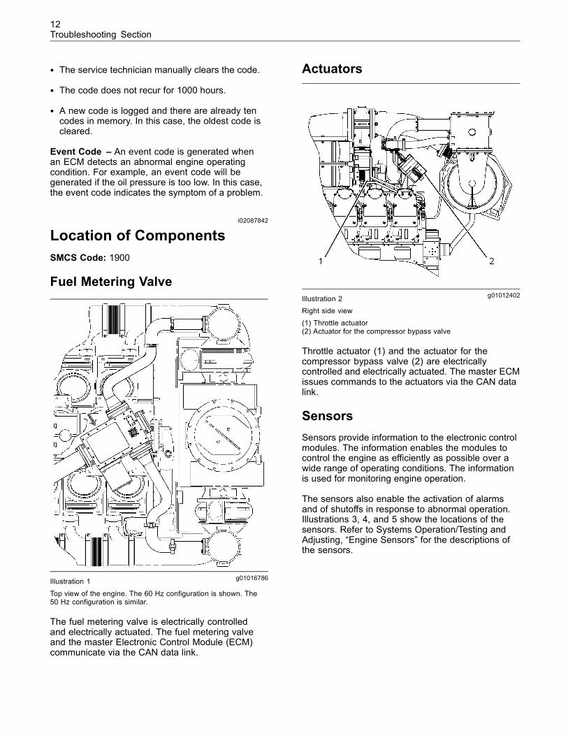
Fuel Metering Valve
g01016786Illustration 1
Top view of the engine. The 60 Hz configuration is shown. The50 Hz configuration is similar.
The fuel metering valve is electrically controlledand electrically actuated. The fuel metering valveand the master Electronic Control Module (ECM)communicate via the CAN data link.
Actuators
g01012402Illustration 2Right side view
(1) Throttle actuator(2) Actuator for the compressor bypass valve
Throttle actuator (1) and the actuator for thecompressor bypass valve (2) are electricallycontrolled and electrically actuated. The master ECMissues commands to the actuators via the CAN datalink.
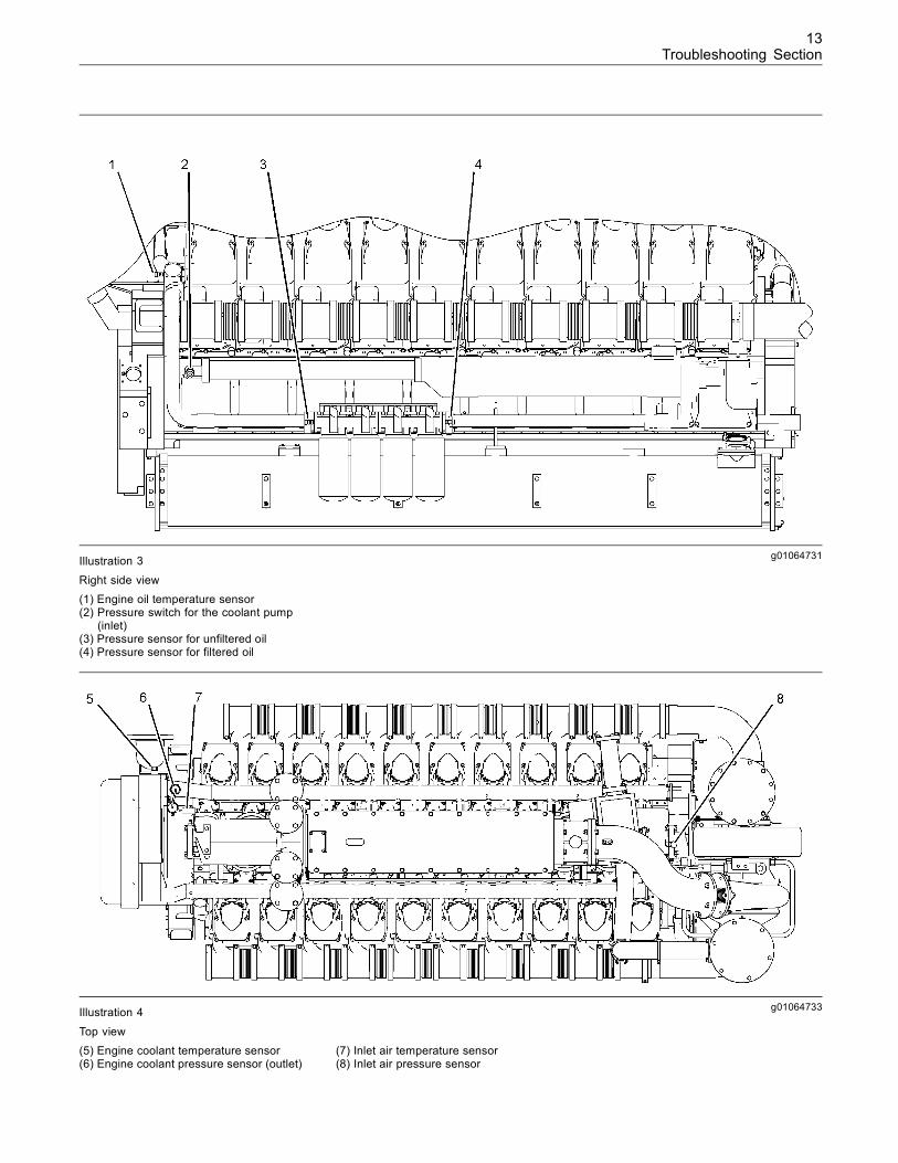
SensorsSensors provide information to the electronic controlmodules. The information enables the modules tocontrol the engine as efficiently as possible over awide range of operating conditions. The informationis used for monitoring engine operation.
The sensors also enable the activation of alarmsand of shutoffs in response to abnormal operation.Illustrations 3, 4, and 5 show the locations of thesensors. Refer to Systems Operation/Testing andAdjusting, “Engine Sensors” for the descriptions ofthe sensors.
13Troubleshooting Section
g01064731Illustration 3
Right side view(1) Engine oil temperature sensor(2) Pressure switch for the coolant pump
(inlet)(3) Pressure sensor for unfiltered oil(4) Pressure sensor for filtered oil
g01064733Illustration 4
Top view(5) Engine coolant temperature sensor(6) Engine coolant pressure sensor (outlet)
(7) Inlet air temperature sensor(8) Inlet air pressure sensor
14Troubleshooting Section
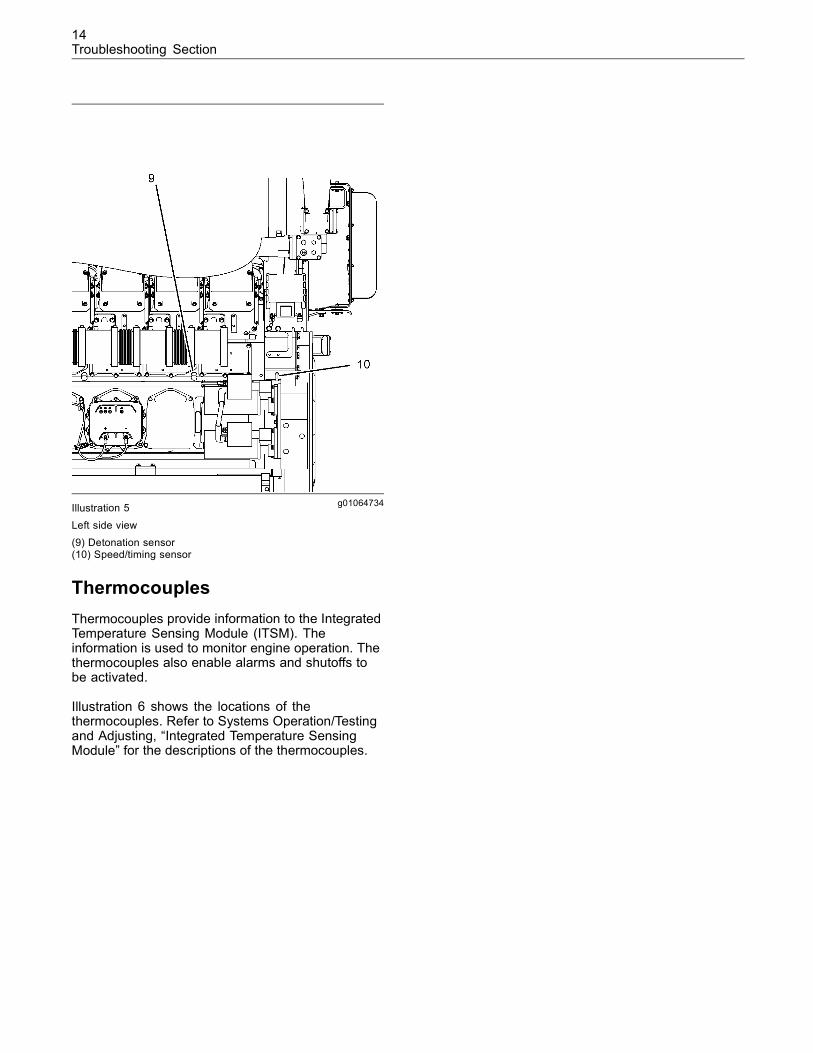
g01064734Illustration 5
Left side view(9) Detonation sensor(10) Speed/timing sensor
ThermocouplesThermocouples provide information to the IntegratedTemperature Sensing Module (ITSM). Theinformation is used to monitor engine operation. Thethermocouples also enable alarms and shutoffs tobe activated.
Illustration 6 shows the locations of thethermocouples. Refer to Systems Operation/Testingand Adjusting, “Integrated Temperature SensingModule” for the descriptions of the thermocouples.
15Troubleshooting Section
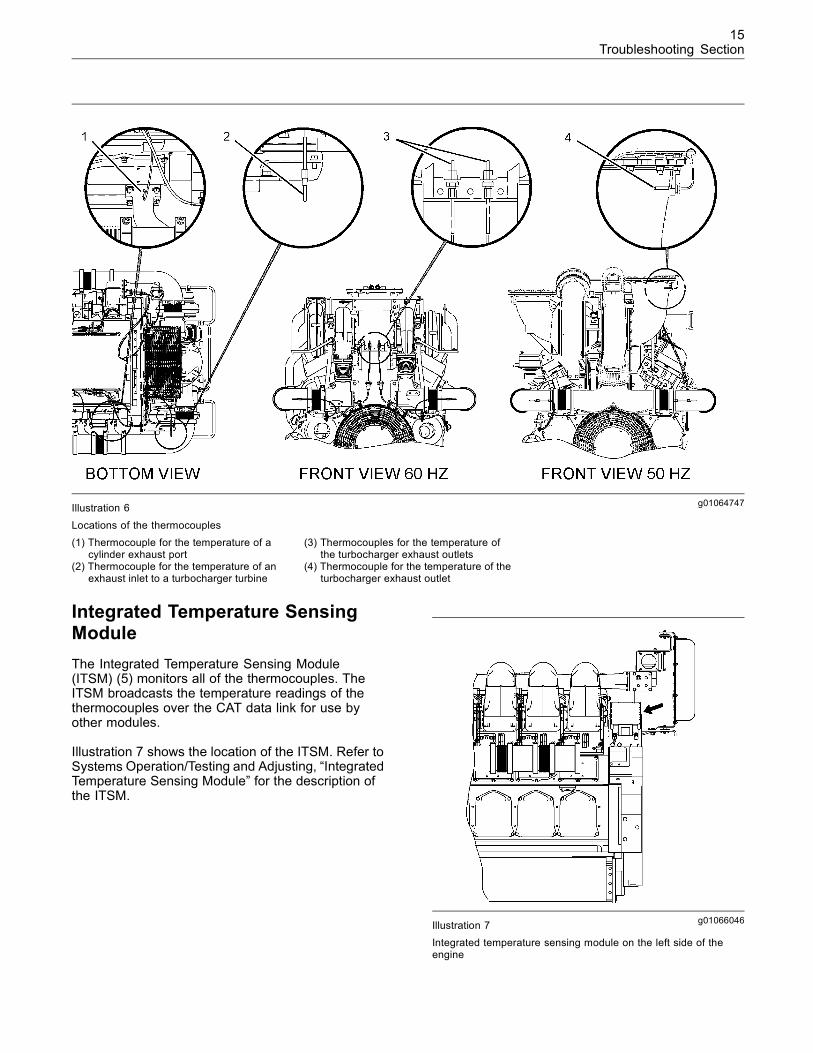
g01064747Illustration 6
Locations of the thermocouples(1) Thermocouple for the temperature of a
cylinder exhaust port(2) Thermocouple for the temperature of an
exhaust inlet to a turbocharger turbine
(3) Thermocouples for the temperature ofthe turbocharger exhaust outlets
(4) Thermocouple for the temperature of theturbocharger exhaust outlet
Integrated Temperature SensingModuleThe Integrated Temperature Sensing Module(ITSM) (5) monitors all of the thermocouples. TheITSM broadcasts the temperature readings of thethermocouples over the CAT data link for use byother modules.
Illustration 7 shows the location of the ITSM. Refer toSystems Operation/Testing and Adjusting, “IntegratedTemperature Sensing Module” for the description ofthe ITSM.
g01066046Illustration 7Integrated temperature sensing module on the left side of theengine
16Troubleshooting Section
i02088018
Electrical Connectors andFunctionsSMCS Code: 7553-WW
Harness Wire IdentificationCaterpillar identifies different wires with elevendifferent solid colors. Table 1 lists the color codes ofthe wiring.
Table 1
Color Codes for Wiring
Code Color
BK Black
BR Brown
BU Blue
GN Green
GY Gray
OR Orange
PK Pink
PU Purple
RD Red
WH White
YL Yellow
In addition to the color, the entire length of eachwire is stamped with a specific circuit number that isrepeated on every 25 mm (1 inch) of the wire. Theactual wires are identified on the schematic.
For example, a code of J011-RD on the schematicidentifies a red wire that is stamped with the circuitnumber J011. This particular wire is the engineharness wire for the primary signal of the transformerin the number one cylinder. For all Caterpillar engineharnesses with electronic ignition systems, the codeof J011-RD identifies the wire for the primary signalof the transformer in the number one cylinder.
The schematic also identifies the size of the wire.The size or gauge of the wire is called the AmericanWire Gauge (AWG). Unless the schematic specifiesa different size, you may assume that the wire is 16AWG.
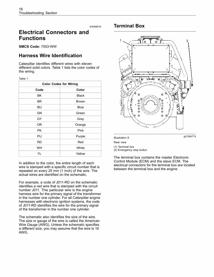
Terminal Box
g01064774Illustration 8
Rear view(1) Terminal box(2) Emergency stop button
The terminal box contains the master ElectronicControl Module (ECM) and the slave ECM. Theelectrical connectors for the terminal box are locatedbetween the terminal box and the engine.
17Troubleshooting Section
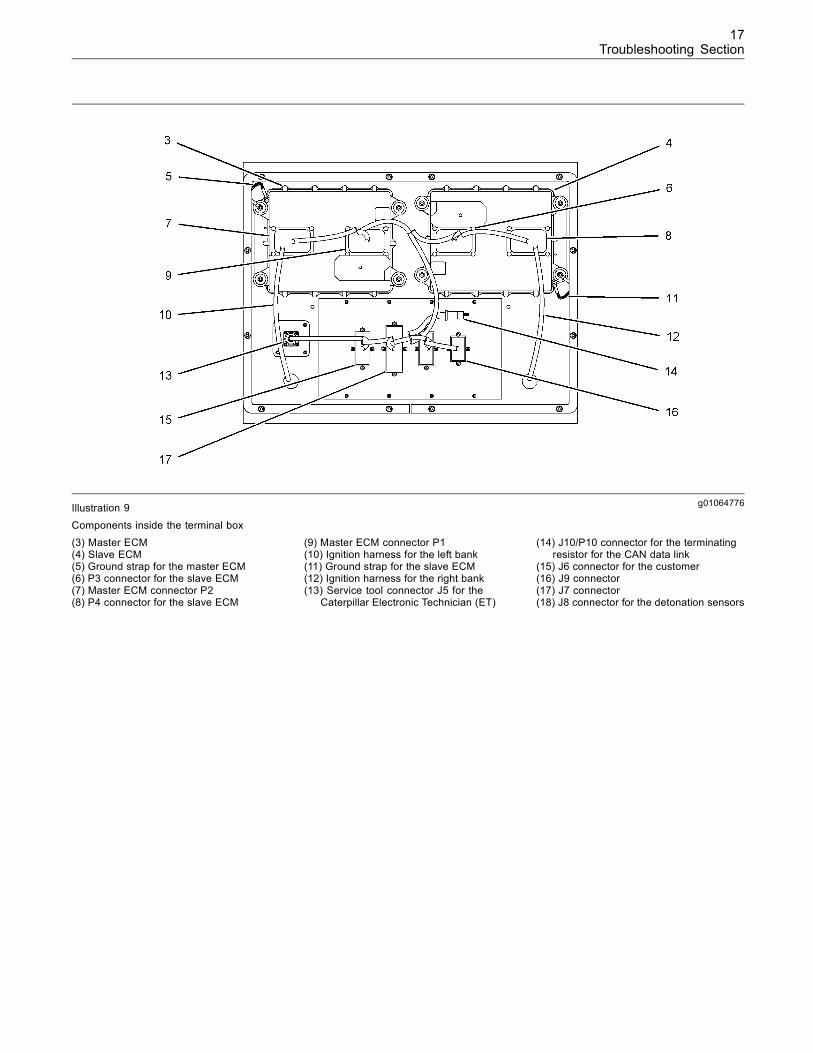
g01064776Illustration 9
Components inside the terminal box(3) Master ECM(4) Slave ECM(5) Ground strap for the master ECM(6) P3 connector for the slave ECM(7) Master ECM connector P2(8) P4 connector for the slave ECM
(9) Master ECM connector P1(10) Ignition harness for the left bank(11) Ground strap for the slave ECM(12) Ignition harness for the right bank(13) Service tool connector J5 for the
Caterpillar Electronic Technician (ET)
(14) J10/P10 connector for the terminatingresistor for the CAN data link
(15) J6 connector for the customer(16) J9 connector(17) J7 connector(18) J8 connector for the detonation sensors
18Troubleshooting Section
Junction Box
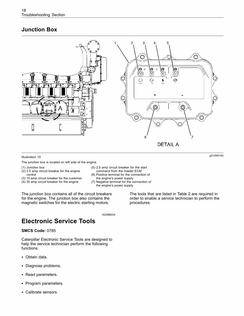
g01059145Illustration 10The junction box is located on left side of the engine.
(1) Junction box(2) 2.5 amp circuit breaker for the engine
control(3) 10 amp circuit breaker for the customer(4) 35 amp circuit breaker for the engine
(5) 2.5 amp circuit breaker for the startcommand from the master ECM
(6) Positive terminal for the connection ofthe engine’s power supply
(7) Negative terminal for the connection ofthe engine’s power supply
The junction box contains all of the circuit breakersfor the engine. The junction box also contains themagnetic switches for the electric starting motors.
i02088034
Electronic Service ToolsSMCS Code: 0785
Caterpillar Electronic Service Tools are designed tohelp the service technician perform the followingfunctions:
• Obtain data.
• Diagnose problems.
• Read parameters.
• Program parameters.
• Calibrate sensors.
The tools that are listed in Table 2 are required inorder to enable a service technician to perform theprocedures.
19Troubleshooting Section
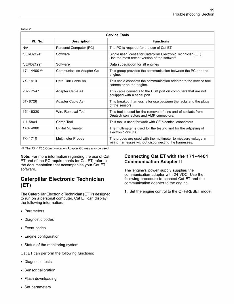
Table 2
Service Tools
Pt. No. Description Functions
N/A Personal Computer (PC) The PC is required for the use of Cat ET.
“JERD2124” Software Single user license for Caterpillar Electronic Technician (ET)Use the most recent version of the software.
“JERD2129” Software Data subscription for all engines
171-4400 (1) Communication Adapter Gp This group provides the communication between the PC and theengine.
7X-1414 Data Link Cable As This cable connects the communication adapter to the service toolconnector on the engine.
237-7547 Adapter Cable As This cable connects to the USB port on computers that are notequipped with a serial port.
8T-8726 Adapter Cable As This breakout harness is for use between the jacks and the plugsof the sensors.
151-6320 Wire Removal Tool This tool is used for the removal of pins and of sockets fromDeutsch connectors and AMP connectors.
1U-5804 Crimp Tool This tool is used for work with CE electrical connectors.
146-4080 Digital Multimeter The multimeter is used for the testing and for the adjusting ofelectronic circuits.
7X-1710 Multimeter Probes The probes are used with the multimeter to measure voltage inwiring harnesses without disconnecting the harnesses.
(1) The 7X-1700 Communication Adapter Gp may also be used.
Note: For more information regarding the use of CatET and of the PC requirements for Cat ET, refer tothe documentation that accompanies your Cat ETsoftware.
Caterpillar Electronic Technician(ET)The Caterpillar Electronic Technician (ET) is designedto run on a personal computer. Cat ET can displaythe following information:
• Parameters
• Diagnostic codes
• Event codes
• Engine configuration
• Status of the monitoring system
Cat ET can perform the following functions:
• Diagnostic tests
• Sensor calibration
• Flash downloading
• Set parameters
Connecting Cat ET with the 171-4401Communication Adapter II
The engine’s power supply supplies thecommunication adapter with 24 VDC. Use thefollowing procedure to connect Cat ET and thecommunication adapter to the engine.
1. Set the engine control to the OFF/RESET mode.
20Troubleshooting Section
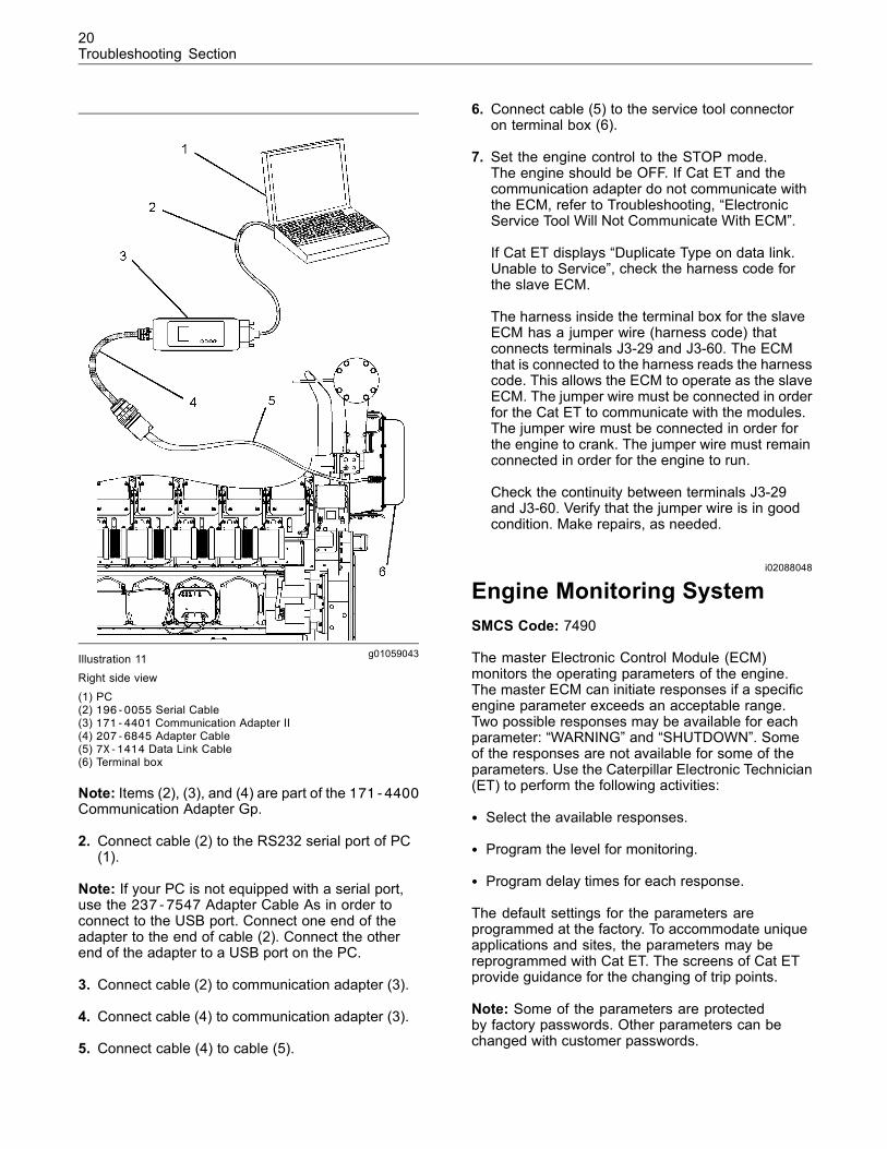
g01059043Illustration 11Right side view(1) PC(2) 196-0055 Serial Cable(3) 171-4401 Communication Adapter II(4) 207-6845 Adapter Cable(5) 7X-1414 Data Link Cable(6) Terminal box
Note: Items (2), (3), and (4) are part of the 171-4400Communication Adapter Gp.
2. Connect cable (2) to the RS232 serial port of PC(1).
Note: If your PC is not equipped with a serial port,use the 237-7547 Adapter Cable As in order toconnect to the USB port. Connect one end of theadapter to the end of cable (2). Connect the otherend of the adapter to a USB port on the PC.
3. Connect cable (2) to communication adapter (3).
4. Connect cable (4) to communication adapter (3).
5. Connect cable (4) to cable (5).
6. Connect cable (5) to the service tool connectoron terminal box (6).
7. Set the engine control to the STOP mode.The engine should be OFF. If Cat ET and thecommunication adapter do not communicate withthe ECM, refer to Troubleshooting, “ElectronicService Tool Will Not Communicate With ECM”.
If Cat ET displays “Duplicate Type on data link.Unable to Service”, check the harness code forthe slave ECM.
The harness inside the terminal box for the slaveECM has a jumper wire (harness code) thatconnects terminals J3-29 and J3-60. The ECMthat is connected to the harness reads the harnesscode. This allows the ECM to operate as the slaveECM. The jumper wire must be connected in orderfor the Cat ET to communicate with the modules.The jumper wire must be connected in order forthe engine to crank. The jumper wire must remainconnected in order for the engine to run.
Check the continuity between terminals J3-29and J3-60. Verify that the jumper wire is in goodcondition. Make repairs, as needed.
i02088048
Engine Monitoring SystemSMCS Code: 7490
The master Electronic Control Module (ECM)monitors the operating parameters of the engine.The master ECM can initiate responses if a specificengine parameter exceeds an acceptable range.Two possible responses may be available for eachparameter: “WARNING” and “SHUTDOWN”. Someof the responses are not available for some of theparameters. Use the Caterpillar Electronic Technician(ET) to perform the following activities:
• Select the available responses.
• Program the level for monitoring.
• Program delay times for each response.
The default settings for the parameters areprogrammed at the factory. To accommodate uniqueapplications and sites, the parameters may bereprogrammed with Cat ET. The screens of Cat ETprovide guidance for the changing of trip points.
Note: Some of the parameters are protectedby factory passwords. Other parameters can bechanged with customer passwords.
21Troubleshooting Section
Changing the Settings of theMonitoring SystemUse the following procedure to change settings ofthe parameters:
1. Use Cat ET and select the “Service/MonitoringSystem” screen.
2. Highlight the desired parameter. Then click on the“Change” button in the lower left corner of thescreen.
The “Change Monitor System” screen will appear.
3. Change the “State” to “On” or “Off”.
4. Set the “Trip Point” and the “Delay Time” accordingto the “Allowed Values” in the lower half of thescreen.
5. Click the “OK” button.
If a password is required, the “Enter Passwords”screen will appear. Enter the correct passwordsand then click the “OK” button.
The new settings will be effective immediately.
Monitoring Parameters
“Low System Voltage”
The trip point for this parameter is set at the factory.The trip point cannot be changed. This parameteris always ON. This parameter cannot be turned off.If the system voltage decreases to the trip point orif the system voltage goes below the trip point, theECM will generate a warning or a shutdown.
“High Engine Coolant Temperature”
The trip points for this parameter can be programmedby the customer. The shutdown response is alwaysON. The shutdown response cannot be turned off. Ifthe engine coolant temperature increases to the trippoint or if the engine coolant temperature exceedsthe trip point, the ECM will generate a warning or ashutdown.
“Low Engine Coolant Temperature”
The trip point for this parameter can be programmedby the customer. If the engine coolant temperaturedecreases to the trip point or if the engine coolanttemperature goes below the trip point, the ECM willgenerate a warning.
“Engine Overspeed”
The trip point for this parameter is set at the factory.This parameter is always ON. This parameter cannotbe turned off. If the engine speed increases to the trippoint or if the engine speed exceeds the trip point,the ECM will activate an engine shutdown. A typicaltrip point is 118 percent of the engine’s rated speedfor generator set applications.
“High Engine Oil Temperature”
The trip point for a warning for this parameter canbe programmed by the customer. The trip point fora shutdown is set at the factory. This parameter isalways ON. This parameter cannot be turned off. Ifthe engine oil temperature increases to the trip pointor if the engine oil temperature exceeds the trip point,the ECM will generate a warning or a shutdown.
“High Oil Filter Differential Pressure”
The trip point for a warning for this parameter canbe programmed by the customer. The trip point fora shutdown is set at the factory. This parameter isalways ON. This parameter cannot be turned off. Ifthe engine oil filter differential pressure increasesto the trip point or if the engine oil filter differentialpressure exceeds the trip point, the ECM willgenerate a warning or a shutdown.
“Low Oil Filter Differential Pressure”
The trip point for a warning for this parameter canbe programmed by the customer. The trip point for ashutdown for this parameter is set at the factory. Thisparameter is always ON. This parameter cannot beturned off. If the engine oil filter differential pressuredecreases to the trip point or if the engine oil filterdifferential pressure goes below the trip point, theECM will generate a warning or a shutdown.
“High Fuel Temperature”
The trip point for this parameter can be programmedby the customer. If the fuel temperature increases tothe trip point or if the fuel temperature exceeds thetrip point, the ECM will generate a warning.
“Low Fuel Pressure”
The trip point for this parameter can be programmedby the customer. If the fuel pressure decreases to thetrip point or if the fuel pressure goes below the trippoint, the ECM will generate a warning.
22Troubleshooting Section
“High Engine Oil to Engine CoolantDifferential Temperature”
The trip point for a warning for this parameter canbe programmed by the customer. The trip point for ashutdown for this parameter is set at the factory. Theshutdown response is always ON. The shutdownresponse cannot be turned off. If the differentialtemperature of the jacket water and the engineoil increases to the trip point or if the differentialtemperature of the jacket water and the engine oilexceeds the trip point, the ECM will generate awarning or a shutdown.
“Low Gas Fuel Differential Pressure”
The trip point for this parameter can be programmedby the customer. If the fuel differential pressuredecreases to the trip point or if the fuel differentialpressure goes below the trip point, the ECM willgenerate a warning.
“High Gas Fuel Differential Pressure”
The trip point for this parameter can be programmedby the customer. If the fuel differential pressureincreases to the trip point or if the fuel differentialpressure exceeds the trip point, the ECM willgenerate a warning.
“High System Voltage”
The trip point for this parameter is set at the factory.The trip point cannot be changed. This parameter isalways ON. This parameter cannot be turned off. Ifthe system voltage increases to the trip point or ifthe system voltage exceeds the trip point, the ECMwill generate a warning.
Trip Points of the Engine Load for HighInlet Air Temperature
The trip points for these parameters can beprogrammed by the customer. The shutdownresponse is always ON. The shutdown responsecannot be turned off. This feature provides a trip pointbetween high engine load and low engine load. Thetrip point is used for events that involve high inlet airtemperature. The trip point for the events is basedon the engine load. The possible responses of thesystem include a warning or a shutdown.
If the load is greater than the trip point, the trip pointfor the “High Inlet Air Temperature at High EngineLoad” event is used for the logging of the high inletair temperature.
If the load is less than the trip point, the trip pointfor the “High Inlet Air Temperature at Low EngineLoad” event is used for the logging of the high inletair temperature.
“High Inlet Air Temperature at LowEngine Load”
The “Service/Configuration” screen of Cat ET definesthe “High Inlet Air Temp Engine Load Set Point”. TheECM can activate a warning or a shutdown if the inletair temperature increases to the trip point or if theinlet air temperature exceeds the trip point during thelow load operation that is defined.
“High Inlet Air Temperature at HighEngine Load”
The “Service/Configuration” screen of Cat ET definesthe “High Inlet Air Temp Engine Load Set Point”. TheECM can activate a warning or a shutdown if the inletair temperature increases to the trip point or if theinlet air temperature exceeds the trip point during thehigh load operation that is defined.
“High Fuel Pressure”
The trip point for this parameter can be programmedby the customer. The ECM will activate a warning ifthe fuel pressure increases to the trip point or if thefuel pressure exceeds the trip point.
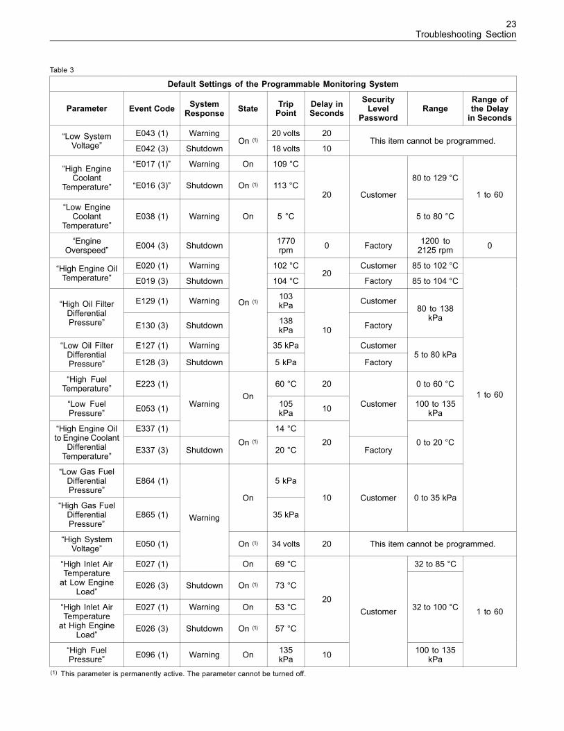
Default Settings of the MonitoringSystemExamples of the default settings for the parametersare listed in Table 3. The values may have changed.Use the Cat ET to determine the programming foryour engine. Many of the items can be reprogrammedin order to accommodate the requirements ofindividual sites.
23Troubleshooting Section
Table 3
Default Settings of the Programmable Monitoring System
Parameter Event Code SystemResponse State Trip
PointDelay inSeconds
SecurityLevel
PasswordRange
Range ofthe Delayin Seconds
E043 (1) Warning 20 volts 20“Low SystemVoltage” E042 (3) Shutdown
On (1)
18 volts 10This item cannot be programmed.
“E017 (1)” Warning On 109 °C“High EngineCoolant
Temperature” “E016 (3)” Shutdown On (1) 113 °C80 to 129 °C
“Low EngineCoolant
Temperature”E038 (1) Warning On 5 °C
20 Customer
5 to 80 °C
1 to 60
“EngineOverspeed” E004 (3) Shutdown 1770
rpm 0 Factory 1200 to2125 rpm 0
E020 (1) Warning 102 °C Customer 85 to 102 °C“High Engine OilTemperature” E019 (3) Shutdown 104 °C
20Factory 85 to 104 °C
E129 (1) Warning 103kPa Customer“High Oil Filter
DifferentialPressure” E130 (3) Shutdown 138
kPa Factory
80 to 138kPa
E127 (1) Warning 35 kPa Customer“Low Oil FilterDifferentialPressure” E128 (3) Shutdown
On (1)
5 kPa
10
Factory5 to 80 kPa
“High FuelTemperature” E223 (1) 60 °C 20 0 to 60 °C
“Low FuelPressure” E053 (1)
On105kPa 10 100 to 135
kPa
E337 (1)
Warning
14 °C
Customer
“High Engine Oilto Engine Coolant
DifferentialTemperature”
E337 (3) ShutdownOn (1)
20 °C20
Factory0 to 20 °C
“Low Gas FuelDifferentialPressure”
E864 (1) 5 kPa
“High Gas FuelDifferentialPressure”
E865 (1)
On
35 kPa
10 Customer 0 to 35 kPa
1 to 60
“High SystemVoltage” E050 (1) On (1) 34 volts 20 This item cannot be programmed.
E027 (1)
Warning
On 69 °C 32 to 85 °C“High Inlet AirTemperatureat Low Engine
Load”E026 (3) Shutdown On (1) 73 °C
E027 (1) Warning On 53 °C“High Inlet AirTemperatureat High Engine
Load”E026 (3) Shutdown On (1) 57 °C
2032 to 100 °C
“High FuelPressure” E096 (1) Warning On 135
kPa 10
Customer
100 to 135kPa
1 to 60
(1) This parameter is permanently active. The parameter cannot be turned off.
24Troubleshooting Section
Separate timers are used in the master ECM for eachresponse that is associated with a parameter. If a trippoint is exceeded, the timer for that event is started.
For example, the warning for “High Engine CoolantTemperature E017 (1)” can be set to 95 °C with a fivesecond delay. The timer starts counting if the coolanttemperature exceeds 95 °C. If the temperature is notreduced to less than 95 °C within five seconds, theevent becomes active and the event is logged.
Conditions for Parameters
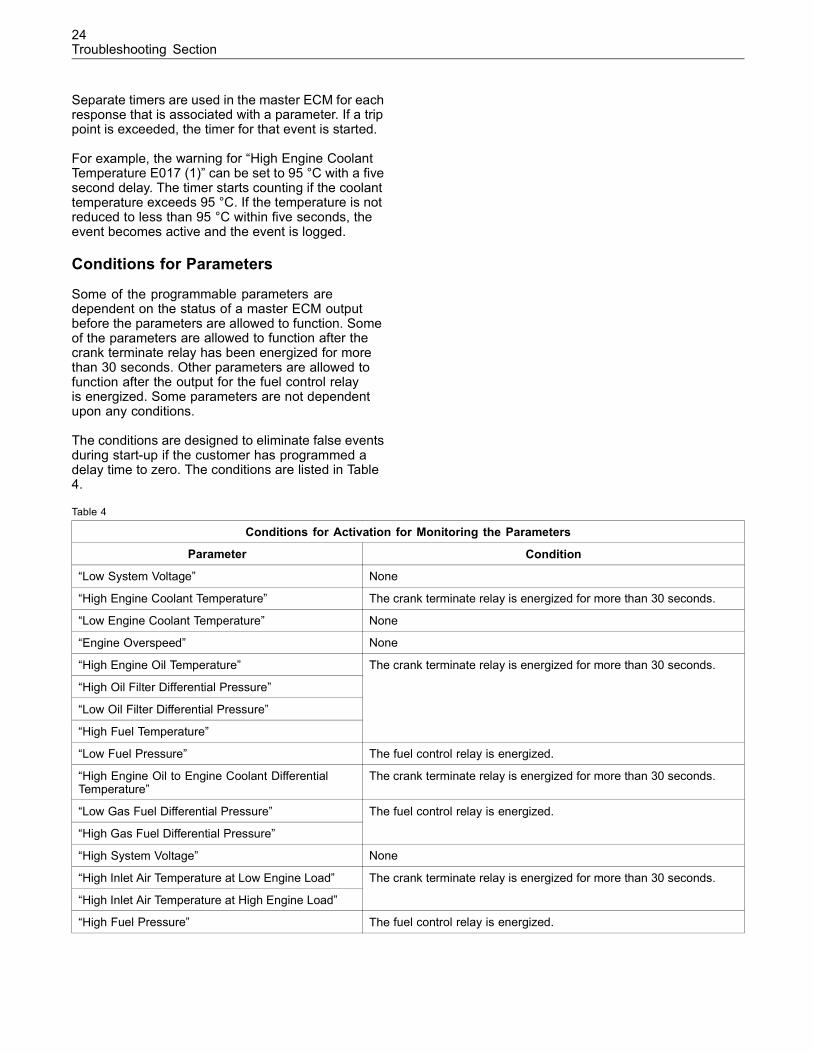
Some of the programmable parameters aredependent on the status of a master ECM outputbefore the parameters are allowed to function. Someof the parameters are allowed to function after thecrank terminate relay has been energized for morethan 30 seconds. Other parameters are allowed tofunction after the output for the fuel control relayis energized. Some parameters are not dependentupon any conditions.
The conditions are designed to eliminate false eventsduring start-up if the customer has programmed adelay time to zero. The conditions are listed in Table4.
Table 4
Conditions for Activation for Monitoring the Parameters
Parameter Condition
“Low System Voltage” None
“High Engine Coolant Temperature” The crank terminate relay is energized for more than 30 seconds.
“Low Engine Coolant Temperature” None
“Engine Overspeed” None
“High Engine Oil Temperature”
“High Oil Filter Differential Pressure”
“Low Oil Filter Differential Pressure”
“High Fuel Temperature”
The crank terminate relay is energized for more than 30 seconds.
“Low Fuel Pressure” The fuel control relay is energized.
“High Engine Oil to Engine Coolant DifferentialTemperature”
The crank terminate relay is energized for more than 30 seconds.
“Low Gas Fuel Differential Pressure”
“High Gas Fuel Differential Pressure”
The fuel control relay is energized.
“High System Voltage” None
“High Inlet Air Temperature at Low Engine Load”
“High Inlet Air Temperature at High Engine Load”
The crank terminate relay is energized for more than 30 seconds.
“High Fuel Pressure” The fuel control relay is energized.
25Troubleshooting Section
Use care when you program the trip points and thedelay times. Ensure that the response of the masterECM is correct for the application. The monitoringsystem will accept any settings within the ranges.
If the trip point for a shutdown is programmed toactivate before the trip point for a warning, the enginewill shut down and the warning will not be activated.
Programmable Parameters of theIntegrated Temperature SensingModuleThe Integrated Temperature Sensing Module (ITSM)monitors the temperatures of the cylinder exhaustports, of the inlets of the turbocharger turbine, and ofthe outlets of the turbocharger turbines.
If a temperature exceeds an acceptable range, theITSM can initiate a “WARNING” or “SHUTDOWN”.Both of the responses are available for all of theparameters. Use Cat ET to perform the followingactivities:
• Select the available responses.
• Program the level for monitoring.
• Program delay times for each response.
Note: To initiate the responses, the ITSM sendscommands to the master ECM via the Cat Data Link.If the connection between the ITSM and the masterECM is not correct, the ITSM cannot initiate anyresponse.
The default settings for the parameters areprogrammed at the factory. To accommodate uniqueapplications and sites, the parameters may bereprogrammed with Cat ET. The screens of Cat ETprovide guidance for changing trip points.
Table 5 lists default examples of the values for theparameters. However, the values may have changed.Use Cat ET to determine the programming for yourengine. The items can be reprogrammed in order toaccommodate the requirements of individual sites.
Use care when you program the trip points and thedelay times. Ensure that the response of the ITSM iscorrect for the application. The monitoring system willaccept any setting within the ranges.
If the trip point for a shutdown is programmed toactivate before the trip point for a warning, the enginewill shut down and the warning will not be activated.
26Troubleshooting Section
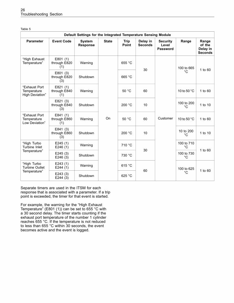
Table 5
Default Settings for the Integrated Temperature Sensing Module
Parameter Event Code SystemResponse
State TripPoint
Delay inSeconds
SecurityLevel
Password
Range Rangeof theDelay inSeconds
E801 (1)through E820
(1)Warning 655 °C
“High ExhaustTemperature”
E801 (3)through E820
(3)Shutdown 665 °C
30 100 to 665°C 1 to 60
E821 (1)through E840
(1)Warning 50 °C 60 10 to 50 °C 1 to 60
“Exhaust PortTemperatureHigh Deviation”
E821 (3)through E840
(3)Shutdown 200 °C 10 100 to 200
°C 1 to 10
E841 (1)through E860
(1)Warning 50 °C 60 10 to 50 °C 1 to 60
“Exhaust PortTemperatureLow Deviation”
E841 (3)through E860
(3)Shutdown 200 °C 10 10 to 200
°C 1 to 10
E245 (1)E246 (1) Warning 710 °C 100 to 710
°C“High TurboTurbine InletTemperature”
E245 (3)E246 (3) Shutdown 730 °C
30100 to 730
°C
1 to 60
E243 (1)E244 (1) Warning 615 °C“High Turbo
Turbine OutletTemperature”
E243 (3)E244 (3) Shutdown
On
625 °C60
Customer
100 to 625°C 1 to 60
Separate timers are used in the ITSM for eachresponse that is associated with a parameter. If a trippoint is exceeded, the timer for that event is started.
For example, the warning for the “High ExhaustTemperature” (E801 (1)) can be set to 655 °C witha 30 second delay. The timer starts counting if theexhaust port temperature of the number 1 cylinderreaches 655 °C. If the temperature is not reducedto less than 655 °C within 30 seconds, the eventbecomes active and the event is logged.
27Troubleshooting Section
Programming Parametersi01829539
Programming ParametersSMCS Code: 1901
Programmable parameters enable the engine to beconfigured in order to meet the requirements of theapplication. The system configuration parametersmust be programmed when the application isinstalled. Perform this programming before the initialengine start-up.
Data from a gas analysis and data on engineperformance are required in order to determine thecorrect settings for the ignition timing and the fuelcontrol. Incorrect programming of parameters maylead to complaints about performance and/or toengine damage.
Programmable parameters can be classified into thefollowing types: engine identification, timing control,air/fuel ratio control, speed control, and start/stopcontrol.
If an Electronic Control Module (ECM) is replaced, theappropriate parameters must be copied from the oldECM. This can be done with the “Copy Configuration”feature of the Caterpillar Electronic Technician (ET).Alternatively, the settings can be recorded on paperand then programmed into the new module.
NOTICEChanging the parameters during engine operation cancause the engine to operate erratically. This can causeengine damage.
Only change the settings of the parameters when theengine is STOPPED.
i01902441
Customer PasswordsSMCS Code: 0785
Certain monitoring system parameters and systemconfiguration parameters may be protected withcustomer passwords. Use of the passwords helpsto prevent free access to the modification of theparameters. If the customer passwords are notprogrammed, all of the parameters are unprotected.
The customer passwords can be changed, ifnecessary. The customer passwords or a factorypassword is needed in order to change the customerpasswords. If the customer passwords are forgotten,factory passwords can be acquired from Caterpillar.
After the customer passwords are entered, thepasswords are required in order to change certainparameters. Once the passwords are enteredsuccessfully, the passwords are not requested againuntil another screen is accessed or the data link isinterrupted.
This feature is enabled by programming two customerpasswords. Use the following procedure to programthe passwords. The same procedure is used tochange the passwords:
1. Access the “Service/Configuration” screen of theCaterpillar Electronic Technician (ET).
2. Highlight the “Customer Password #1” parameter.Click on the “Change” button in the lower rightcorner of the screen.
Note: Be sure to record the customer passwords.Store the passwords securely. The passwords canhave a maximum of eight characters. Alphanumericcharacters may be used. The passwords are casesensitive.
3. Enter the password in the “Change ParameterValue” dialog box and click on the “OK” button.
4. Highlight the “Customer Password #2” parameter.Click on the “Change” button in the lower rightcorner of the screen.
5. Enter the password in the “Change ParameterValue” dialog box and click on the “OK” button.
The passwords are now programmed into thememory of the Master Electronic Control Module(ECM).
Make a copy of Table 6 and record your passwords.Store the passwords securely.
Table 6
Customer Passwords
Customer Password #1
Customer Password #2
i01865997
Factory PasswordsSMCS Code: 0785
Factory level security passwords are required forclearing certain logged events and for changingcertain programmable parameters. Because of thepasswords, only authorized personnel can makechanges to some of the programmable items inan Electronic Control Module (ECM). When thecorrect passwords are entered, the changes areprogrammed into the master ECM.
28Troubleshooting Section
Factory passwords are required to program thefollowing shutdowns:
• “Engine Overspeed”
• “High Engine Oil Temperature”
• “High Oil Filter Differential Pressure”
• “Low Oil Filter Differential”
• “High Engine Oil to Engine Coolant DifferentialTemperature”
The “Enter Factory Passwords” screen on Cat ETwill display the following parameters. To obtain theproper passwords, the information must be given toan authorized Caterpillar dealer:
• Current master ECM
• Serial number of the service tool
• Serial number of the engine
• Serial number of the master ECM
• Diagnostic clock
• Total Tattletale
• Reason
The old interlock code is required to change theinterlock code on a used ECM. The passwords arecontrolled by Caterpillar. The passwords may only beobtained by an authorized Caterpillar dealer.
The passwords may only be used for oneprogramming session. After you exit the “EnterFactory Passwords” screen on Cat ET, a differentset of passwords will be required before you canprogram the master ECM.
Factory passwords are not required for the first hourof operation for a new master ECM. After the hourexpires, factory passwords are required for some ofthe programming.
i02089534
Factory Passwords WorksheetSMCS Code: 0785
The connection of any electrical equipment andthe disconnection of any electrical equipmentmaycause an explosion hazard which may result in in-jury or death. Do not connect any electrical equip-ment or disconnect any electrical equipment in anexplosive atmosphere.
Note: A mistake in recording this information willresult in incorrect passwords.
Table 7
Factory Passwords Worksheet
Dealer Code
Customer’s Name
Address
Telephone Number
Information from the “Enter Factory Passwords”Screen on the Caterpillar Electronic
Technician (Cat ET)
Serial Number for Cat ET
Engine Serial Number
ECM Serial Number
Total Tattletale
Reason Code
Factory Passwords
Factory Password (No. 1)
Factory Password (No. 2)

29Troubleshooting Section
i01866010
Flash ProgrammingSMCS Code: 1901-591
Software is located in the flash memory of the masterElectronic Control Modules (ECM), the slave ECM,and the Integrated Temperature Sensing Module(ITSM). The Caterpillar Electronic Technician (ET)can be used to flash new software into an ECM orthe ITSM. This is the only method for updating thesoftware. The component that contains the softwarecannot be physically removed from the module.This eliminates the risk of moisture entry into amodule due to improper seal installation. The flashis accomplished by transferring the data from CatET to the module via data link wiring. The Software,JERD2124 or Software, JERD2129 is used.
Flash ProgrammingIf the slowest baud rate of Cat ET is selected, flashprogramming can last up to 15 minutes. Be sure toset the baud rate to the fastest rate for your PC.
To select the baud rate, use the “Utilities/Preferences”option on the Cat ET. Select the “Communications”tab and click on “Advanced...”. Then select the baudrate from the “Advanced Communication Settings”menu and click the “OK” button.
If a communication error occurs, select a slower baudrate in order to improve the reliability.
1. Connect Cat ET to the service tool connector.Refer to Troubleshooting, “Electronic ServiceTools”.
2. Set the engine control to the STOP mode.
Cat ET will not flash if the engine control is in theOFF/RESET or START mode.
3. Select “WinFlash” from the “Utilities” menu on theCat ET.
“WinFlash” will try to detect an ECM. Allow a fewmoments for “WinFlash” to detect the electroniccontrol modules and connect to the electroniccontrol modules.
4. When an ECM has been detected, the “ECMSelector” window will appear. Select theappropriate ECM and then select “OK”.
The “Flash File Selection” window will appear.
5. The flash files are located on a disk drive and ina directory. Select the correct disk drive and thedirectory from “Drives” and “Directories” on CatET.
A list of flash files will appear.
6. Select the correct file from the list of flash files.Read the “Description” and the “File Info” in orderto verify that the correct file is selected. Select“Open”.
7. Select the “Begin Flash” button in order to programthe personality module.
When the flash is completed, this message willappear: “Flash Completed Successfully”.
8. Program the configuration parameters and themonitoring system parameters.
The parameters must be programmed in orderto ensure proper engine operation. Refer toTroubleshooting, “Engine Monitoring System”and Troubleshooting, “System ConfigurationParameters”.
9. Start the engine and check for proper operation.
a. If a diagnostic code of 268-02 “CheckProgrammable Parameters” is generated,program any parameters that were not in theoriginal software.
b. Access the “Configuration” screen underthe “Service” menu in order to determinethe parameters that require programming.Look under the “Tattletale” column. All of theparameters should have a tattletale of 1 ormore. If a parameter has a tattletale of 0,program that parameter.
“WinFlash” Error Messages
If you receive any error messages during flashprogramming, click on the “Cancel” button in orderto stop the process. Access the information aboutthe “ECM Summary” under the “Information” menu.Make sure that you are flashing the correct file foryour engine.
i01945454
System ConfigurationParametersSMCS Code: 1901
Certain parameters are unique for each engineapplication. Table 8 is a list of the parameters that canbe configured for G3520C Engines. The parametersare programmed into the Electronic Control Module(ECM) via the Caterpillar Electronic Technician (CatET). The values of the parameters can be viewed onthe “Configuration” screen of Cat ET.
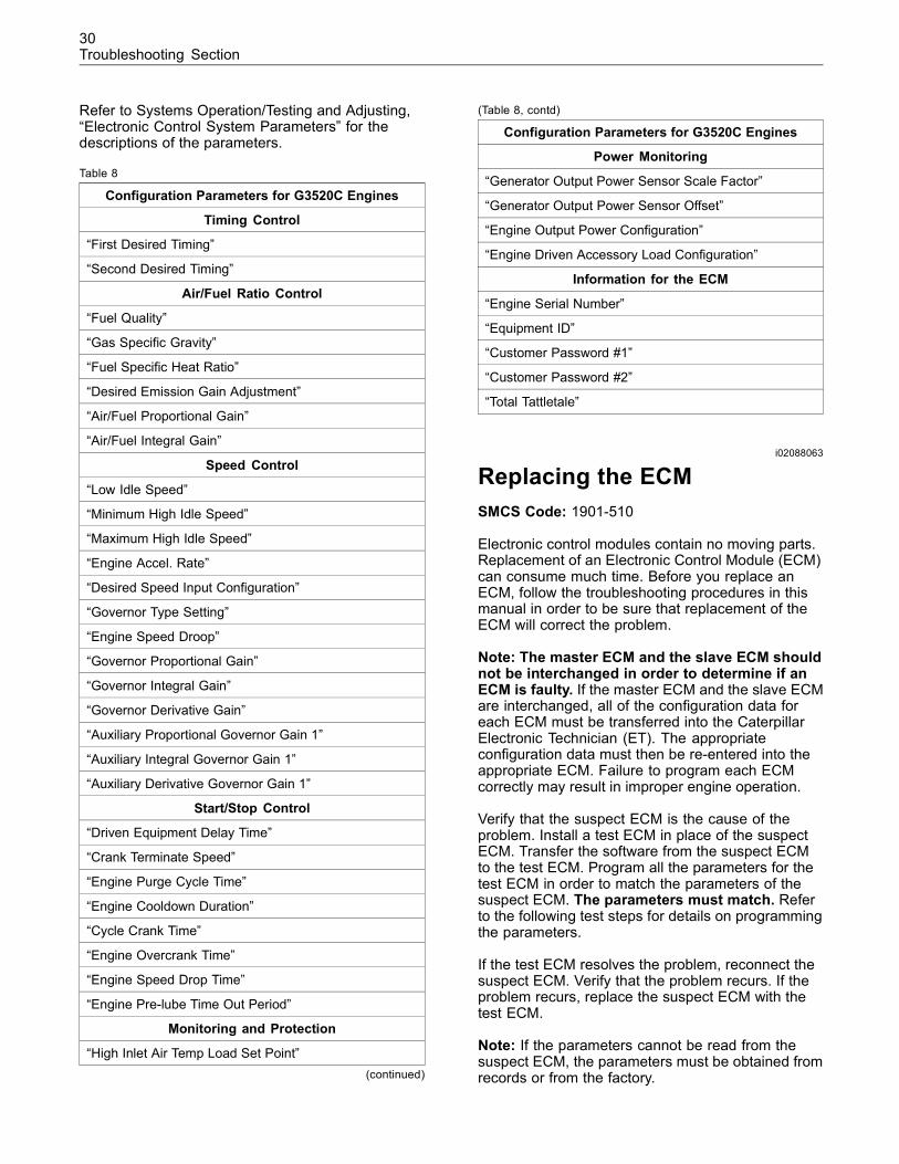
30Troubleshooting Section
Refer to Systems Operation/Testing and Adjusting,“Electronic Control System Parameters” for thedescriptions of the parameters.
Table 8
Configuration Parameters for G3520C Engines
Timing Control
“First Desired Timing”
“Second Desired Timing”
Air/Fuel Ratio Control
“Fuel Quality”
“Gas Specific Gravity”
“Fuel Specific Heat Ratio”
“Desired Emission Gain Adjustment”
“Air/Fuel Proportional Gain”
“Air/Fuel Integral Gain”
Speed Control
“Low Idle Speed”
“Minimum High Idle Speed”
“Maximum High Idle Speed”
“Engine Accel. Rate”
“Desired Speed Input Configuration”
“Governor Type Setting”
“Engine Speed Droop”
“Governor Proportional Gain”
“Governor Integral Gain”
“Governor Derivative Gain”
“Auxiliary Proportional Governor Gain 1”
“Auxiliary Integral Governor Gain 1”
“Auxiliary Derivative Governor Gain 1”
Start/Stop Control
“Driven Equipment Delay Time”
“Crank Terminate Speed”
“Engine Purge Cycle Time”
“Engine Cooldown Duration”
“Cycle Crank Time”
“Engine Overcrank Time”
“Engine Speed Drop Time”
“Engine Pre-lube Time Out Period”
Monitoring and Protection
“High Inlet Air Temp Load Set Point”(continued)
(Table 8, contd)
Configuration Parameters for G3520C Engines
Power Monitoring
“Generator Output Power Sensor Scale Factor”
“Generator Output Power Sensor Offset”
“Engine Output Power Configuration”
“Engine Driven Accessory Load Configuration”
Information for the ECM
“Engine Serial Number”
“Equipment ID”
“Customer Password #1”
“Customer Password #2”
“Total Tattletale”
i02088063
Replacing the ECMSMCS Code: 1901-510
Electronic control modules contain no moving parts.Replacement of an Electronic Control Module (ECM)can consume much time. Before you replace anECM, follow the troubleshooting procedures in thismanual in order to be sure that replacement of theECM will correct the problem.
Note: The master ECM and the slave ECM shouldnot be interchanged in order to determine if anECM is faulty. If the master ECM and the slave ECMare interchanged, all of the configuration data foreach ECM must be transferred into the CaterpillarElectronic Technician (ET). The appropriateconfiguration data must then be re-entered into theappropriate ECM. Failure to program each ECMcorrectly may result in improper engine operation.
Verify that the suspect ECM is the cause of theproblem. Install a test ECM in place of the suspectECM. Transfer the software from the suspect ECMto the test ECM. Program all the parameters for thetest ECM in order to match the parameters of thesuspect ECM. The parameters must match. Referto the following test steps for details on programmingthe parameters.
If the test ECM resolves the problem, reconnect thesuspect ECM. Verify that the problem recurs. If theproblem recurs, replace the suspect ECM with thetest ECM.
Note: If the parameters cannot be read from thesuspect ECM, the parameters must be obtained fromrecords or from the factory.
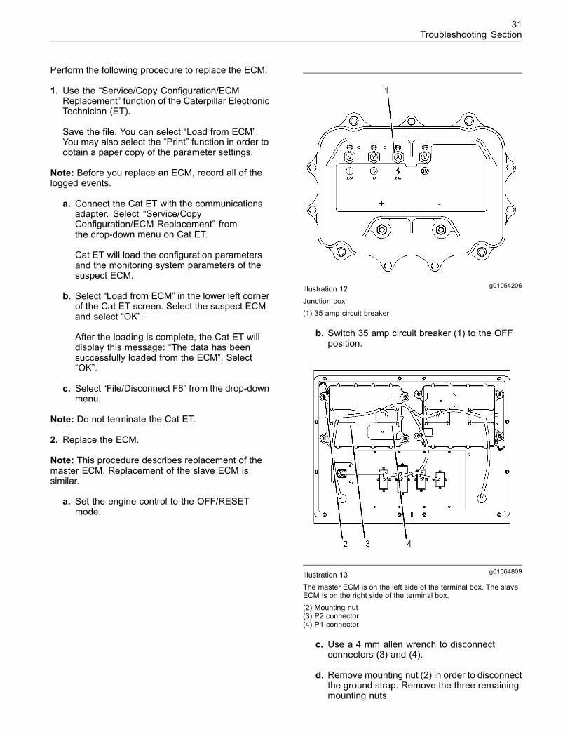
31Troubleshooting Section
Perform the following procedure to replace the ECM.
1. Use the “Service/Copy Configuration/ECMReplacement” function of the Caterpillar ElectronicTechnician (ET).
Save the file. You can select “Load from ECM”.You may also select the “Print” function in order toobtain a paper copy of the parameter settings.
Note: Before you replace an ECM, record all of thelogged events.
a. Connect the Cat ET with the communicationsadapter. Select “Service/CopyConfiguration/ECM Replacement” fromthe drop-down menu on Cat ET.
Cat ET will load the configuration parametersand the monitoring system parameters of thesuspect ECM.
b. Select “Load from ECM” in the lower left cornerof the Cat ET screen. Select the suspect ECMand select “OK”.
After the loading is complete, the Cat ET willdisplay this message: “The data has beensuccessfully loaded from the ECM”. Select“OK”.
c. Select “File/Disconnect F8” from the drop-downmenu.
Note: Do not terminate the Cat ET.
2. Replace the ECM.
Note: This procedure describes replacement of themaster ECM. Replacement of the slave ECM issimilar.
a. Set the engine control to the OFF/RESETmode.
g01054206Illustration 12
Junction box(1) 35 amp circuit breaker
b. Switch 35 amp circuit breaker (1) to the OFFposition.
g01064809Illustration 13The master ECM is on the left side of the terminal box. The slaveECM is on the right side of the terminal box.
(2) Mounting nut(3) P2 connector(4) P1 connector
c. Use a 4 mm allen wrench to disconnectconnectors (3) and (4).
d. Remove mounting nut (2) in order to disconnectthe ground strap. Remove the three remainingmounting nuts.
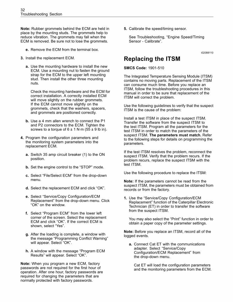
32Troubleshooting Section
Note: Rubber grommets behind the ECM are held inplace by the mounting studs. The grommets help toreduce vibration. The grommets may fall when theECM is removed. Be sure not to lose the grommets.
e. Remove the ECM from the terminal box.
3. Install the replacement ECM.
a. Use the mounting hardware to install the newECM. Use a mounting nut to fasten the groundstrap for the ECM to the upper left mountingstud. Then install the other three mountingnuts.
Check the mounting hardware and the ECM forcorrect installation. A correctly installed ECMwill move slightly on the rubber grommets.If the ECM cannot move slightly on thegrommets, check that the washers, spacers,and grommets are positioned correctly.
b. Use a 4 mm allen wrench to connect the P1and P2 connectors to the ECM. Tighten thescrews to a torque of 6 ± 1 N·m (55 ± 9 lb in).
4. Program the configuration parameters andthe monitoring system parameters into thereplacement ECM.
a. Switch 35 amp circuit breaker (1) to the ONposition.
b. Set the engine control to the “STOP” mode.
c. Select “File/Select ECM” from the drop-downmenu.
d. Select the replacement ECM and click “OK”.
e. Select “Service/Copy Configuration/ECMReplacement” from the drop-down menu. Click“OK” on the window.
f. Select “Program ECM” from the lower leftcorner of the screen. Select the replacementECM and click “OK”. If the correct ECM isshown, select “Yes”.
g. After the loading is complete, a window withthe message “Programming Conflict Warning”will appear. Select “OK”.
h. A window with the message “Program ECMResults” will appear. Select “OK”.
Note: When you program a new ECM, factorypasswords are not required for the first hour ofoperation. After one hour, factory passwords arerequired for changing the parameters that arenormally protected with factory passwords.
5. Calibrate the speed/timing sensor.
See Troubleshooting, “Engine Speed/TimingSensor - Calibrate”.
i02088110
Replacing the ITSMSMCS Code: 1901-510
The Integrated Temperature Sensing Module (ITSM)contains no moving parts. Replacement of the ITSMcan consume much time. Before you replace anITSM, follow the troubleshooting procedures in thismanual in order to be sure that replacement of theITSM will correct the problem.
Use the following guidelines to verify that the suspectITSM is the cause of the problem:
Install a test ITSM in place of the suspect ITSM.Transfer the software from the suspect ITSM tothe test ITSM. Program all the parameters for thetest ITSM in order to match the parameters of thesuspect ITSM. The parameters must match. Referto the following steps for details on programming theparameters.
If the test ITSM resolves the problem, reconnect thesuspect ITSM. Verify that the problem recurs. If theproblem recurs, replace the suspect ITSM with thetest ITSM.
Use the following procedure to replace the ITSM:
Note: If the parameters cannot be read from thesuspect ITSM, the parameters must be obtained fromrecords or from the factory.
1. Use the “Service/Copy Configuration/ECMReplacement” function of the Caterpillar ElectronicTechnician (ET) in order to transfer the softwarefrom the suspect ITSM.
You may also select the “Print” function in order toobtain a paper copy of the parameter settings.
Note: Before you replace an ITSM, record all of thelogged events.
a. Connect Cat ET with the communicationsadapter. Select “Service/CopyConfiguration/ECM Replacement” fromthe drop-down menu.
Cat ET will load the configuration parametersand the monitoring parameters from the ECM.
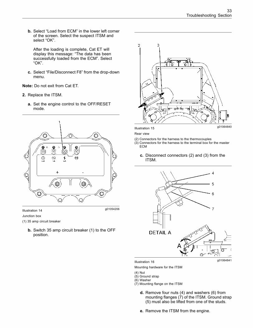
33Troubleshooting Section
b. Select “Load from ECM” in the lower left cornerof the screen. Select the suspect ITSM andselect “OK”.
After the loading is complete, Cat ET willdisplay this message: “The data has beensuccessfully loaded from the ECM”. Select“OK”.
c. Select “File/Disconnect F8” from the drop-downmenu.
Note: Do not exit from Cat ET.
2. Replace the ITSM.
a. Set the engine control to the OFF/RESETmode.
g01054206Illustration 14
Junction box(1) 35 amp circuit breaker
b. Switch 35 amp circuit breaker (1) to the OFFposition.
g01064840Illustration 15
Rear view(2) Connectors for the harness to the thermocouples(3) Connectors for the harness to the terminal box for the master
ECM
c. Disconnect connectors (2) and (3) from theITSM.
g01064841Illustration 16Mounting hardware for the ITSM
(4) Nut(5) Ground strap(6) Washer(7) Mounting flange on the ITSM
d. Remove four nuts (4) and washers (6) frommounting flanges (7) of the ITSM. Ground strap(5) must also be lifted from one of the studs.
e. Remove the ITSM from the engine.
34Troubleshooting Section
3. Install the replacement ITSM. Orient the 54-pinconnector toward the bottom of the engine.
a. Use the mounting hardware to install thenew ITSM. Be sure to install ground strap (5)between one of the washers on the mountingflange and the nut.
Note: One of the washers is a lock washer. Be sureto install the lock washer between ground strap (5)and mounting flange (7). The lock washer improvesthe electrical conductivity between the ground strapand the mounting flange.
Check the mounting hardware and the ITSM forcorrect installation. A properly installed ITSMwill move slightly on the rubber grommets. If theITSM cannot move slightly on the grommets,check that the mounting hardware is installedcorrectly.
b. Connect connectors (2) and (3) to the ITSM.
4. Program the configuration parameters andthe monitoring system parameters into thereplacement ITSM.
a. Switch 35 amp circuit breaker (1) to the ONposition.
b. Set the engine control to the STOP mode.
c. Select “File/Select ECM” from the drop-downmenu of Cat ET.
d. Select the “Replacement ITSM” and click “OK”.
e. Select “Service/Copy Configuration/ECMReplacement” from the drop-down menu. Click“OK” on the window.
f. Select “Program ECM” from the lower leftcorner of the screen. Select the replacementITSM and click “OK”.
g. After the loading is complete, a window withthe message “Programming Complete” willappear. Select “OK”.
Note: When you program a new ITSM, factorypasswords are not required. Also, the ITSM does notrequire calibration.
i02089781
Troubleshooting Data SheetSMCS Code: 0785
To help troubleshoot a gas engine, complete theinformation in Illustration 17. Be sure to include theunits of measurement.
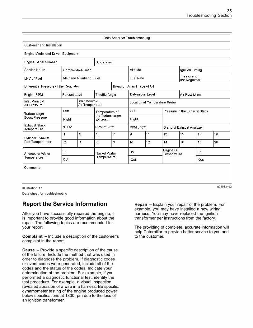
35Troubleshooting Section
g01013492Illustration 17Data sheet for troubleshooting
Report the Service InformationAfter you have successfully repaired the engine, itis important to provide good information about therepair. The following topics are recommended foryour report:
Complaint – Include a description of the customer’scomplaint in the report.
Cause – Provide a specific description of the causeof the failure. Include the method that was used inorder to diagnose the problem. If diagnostic codesor event codes were generated, include all of thecodes and the status of the codes. Indicate yourdetermination of the problem. For example, if youperformed a diagnostic functional test, identify thetest procedure. For example, a visual inspectionrevealed abrasion of a wire in a harness. Be specific:dynamometer testing of the engine produced powerbelow specifications at 1800 rpm due to the loss ofan ignition transformer.
Repair – Explain your repair of the problem. Forexample, you may have installed a new wiringharness. You may have replaced the ignitiontransformer per instructions from the factory.
The providing of complete, accurate information willhelp Caterpillar to provide better service to you andto the customer.
36Troubleshooting Section
Troubleshooting without aDiagnostic Code
i01970297
SymptomsSMCS Code: 1000-035
Some engine symptoms can be unrelated tothe electronic control system. This section is fortroubleshooting problems that have symptomswithout active diagnostic codes. Conditions such aspoor fuel quality or improperly adjusted valves cancause some engine symptoms.
For basic troubleshooting of the engine, performthe following steps first in order to diagnose amalfunction.
1. Gather information about the complaint from theoperator.
2. Verify that the complaint is not due to normalengine operation. Verify that the complaint is notdue to error of the operator.
3. Perform a visual inspection. Inspect the followingitems:
• Fuel supply
• Oil level
• Oil supply
• Coolant level
• Wiring
• Connectors
4. Check the diagnostic codes and event codes.Repair any active codes.
If these inspections do not reveal any problems,identify the probable causes with the procedures inthis manual that best describe the symptoms. Refer toTroubleshooting, “Troubleshooting With A DiagnosticCode” or refer to Troubleshooting, “TroubleshootingWith an Event Code”. Check each probable causeaccording to the tests that are recommended.
Be sure to check the connectors. This is speciallytrue for problems that are intermittent. Refer toTroubleshooting, “Inspecting Electrical Connectors”.
Narrow the probable cause. Consider the operatorinformation, the conditions of operation, and thehistory of the engine.
Operator InformationObtain the following information from the operator:
• The occurrence and the time of the occurrence
• Determine the conditions for the occurrence. Theconditions will include the engine rpm and the load.
• Determine if there are any systems that wereinstalled by the dealer or by the customer thatcould cause the symptom.
• Determine whether any other occurrenceshappened in addition to the symptom.
Diagnostic Codes and Event CodesExamine the following information regarding anycodes:
• The probable cause of the symptom is correlatedto the code.
• The code was generated when the symptomoccurred.
• Codes that are repeatedly logged
• The complaint is not due to normal engineoperation.
Other SymptomsIf other occurrences happened in addition to thesymptom, investigate the following conditions:
• The other occurrences are related to the symptom.
• The symptoms have a probable cause that iscommon.
i02064369
DetonationSMCS Code: 1000-035
Probable Causes• Excessive load
• Excessive inlet manifold air pressure
• High inlet air temperature
37Troubleshooting Section
• Incorrect air/fuel ratio
• Incorrect base timing
• Changes in the fuel quality
• The engine speed/timing sensor is not calibrated.
• Faulty circuit for the detonation sensor(s)
• Excessive deposits in the combustion chamber
Recommended Repairs
Excessive Load
Make sure that the load is not excessive. Reduce theload. If necessary, disengage the driven equipmentand test the engine.
Check the Inlet Manifold Air Pressure
The calculated engine load increases when the inletmanifold air pressure increases. Measure the inletmanifold air pressure during engine operation witha load. For specific data on the engine, refer to theengine Technical Marketing Information.
Check the Inlet Air Temperature
High inlet air temperature can cause detonation.Check the inlet air temperature. Look for the followingevent codes:
• “E026 (3) High Inlet Air Temperature” (shutdown)
• “E027 (1) High Inlet Air Temperature” (warning)
Refer to Troubleshooting, “Inlet Air Temperature(High)”.
Air/Fuel Ratio
An air/fuel mixture that is too rich will causedetonation. Verify that the exhaust emissions arecorrect. Refer to Systems Operation/Testing andAdjusting, “Air/Fuel Ratio Control - Adjust”.
A change in the fuel energy content will change theair/fuel ratio. Obtain a fuel analysis.
The fuel supply pressure must be adequate andstable.
Make sure that the fuel metering valve is operatingcorrectly.
Check the Base Timing
Verify that the base timing is correct. Refer toSystems Operation/Testing and Adjusting, “IgnitionTiming - Adjust”.
Check for Event Codes Regarding theFuel
Check for the following event codes:
• “E229 (1) Fuel Energy Content Setting Low”(warning)
• “E230 (1) Fuel Energy Content Setting High”(warning)
• “E231 (3) Fuel Quality Out Of Range” (shutdown)
Refer to Troubleshooting, “Fuel Energy Content”.
Calibrate the Engine Speed/TimingSensor
Note: Only perform this procedure if work on theengine may have affected the engine timing. Also,perform this procedure if the engine speed/timingsensor has not been calibrated.
Calibrate the engine speed/timing sensor. Refer toTroubleshooting, “Engine Speed/Timing Sensor -Calibrate”.
Check the Detonation Sensors
Troubleshoot the detonation sensors. Refer toTroubleshooting, “Detonation Sensors”.
Check for Deposits in the Cylinders
Overfilling of engine oil can lead to deposits. Makesure that the engine oil level is correct.
Note: Excessive deposits contribute to guttering ofthe valves.
Use a borescope to inspect the cylinders. Look forthe following conditions:
• Deposits on the valve seats
• Deposits on the valve faces
• Deposits on the cylinder walls that are above theupper limit of the piston stroke
• Signs of internal leaks
Signs of internal leaks include excessive consumptionof engine oil, blue smoke, and excessive detonation.
38Troubleshooting Section
If excessive deposits and/or signs of internal leaksare found, investigate the cause of the condition.Make repairs, as needed.
i02088119
Driven EquipmentSMCS Code: 1400-035
Probable Causes• The master Electronic Control Module (ECM) hasreceived a “Start Inhibit” or a “Shutdown” signal.
• The circuit for the signal is faulty.
Recommended Repairs
Check the Driven Equipment
Determine whether the driven equipment hasgenerated a “Start Inhibit” or “Shutdown” request.Determine the cause for the request. Service thedriven equipment according to the recommendationsof the OEM of the equipment.
Check the Circuit for the Switch
The circuit for the switch must remain closed in orderto allow the engine to run. Check the wiring betweenthe driven equipment and the ECM connector fordamage and/or corrosion. Refer to Troubleshooting,“Inspecting Electrical Connectors”. Repair the wiring,as needed.
Check the resistance of the circuit between terminalsP1-21 and P1-31 at the master ECM. The correctresistance of the circuit is 5 Ohms or less. If theresistance is greater than 5 Ohms, locate the sourceof the excessive resistance. Make repairs, as needed.
i01804809
ECM Will Not Accept FactoryPasswordsSMCS Code: 1901-035
Probable CausesOne of the following items may not be recordedcorrectly on the Caterpillar Electronic Technician(ET):
• Passwords
• Serial Numbers
• Total Tattletale
• Reason Code
Recommended Repairs1. Verify that the correct passwords were entered.Check every character in each password. Set theengine control to the OFF/RESET mode for 30seconds and then retry.
2. Verify that Cat ET is on the “Factory Password”screen.
3. Verify that the following information from Cat EThas been recorded correctly:
• Serial Number of the engine
• Serial Number of the Electronic Control Module(ECM)
• Serial Number of the Cat ET
• Total Tattletale
• Reason Code
• Diagnostic Clock
i01804831
Electronic Service Tool WillNot Communicate with ECM(The Caterpillar ElectronicTechnician (ET) Will NotCommunicate With anElectronic Control Module(ECM) and/or the IntegratedTemperature Sensing Module(ITSM))SMCS Code: 0785-035
Probable Causes• Electrical power supply
• Electrical connectors
• Communication adapter and/or cables
• Electronic service tool
• A problem with the harness code for the slave ECM
39Troubleshooting Section
Recommended Repairs
Electrical Power Supply
Check power to the module. Refer to Troubleshooting,“Electrical Power Supply”.
Note: If a module is not receiving power, the modulewill not communicate.
Electrical Connectors
Check the following components:
• Power supply connections and ground to themodule
• Wiring harnesses and the connectors for themodule
Refer to Troubleshooting, “Inspecting ElectricalConnectors”.
Communication Adapter and/or Cables
1. Check the condition of the fuse for thecommunication adapter.
2. Disconnect the communication adapter and thecables from the service tool connector. Thenreconnect the communication adapter.
If you are using the 171-4401 CommunicationAdapter II, refer to Manual, “CommunicationAdapter II User’s Manual”.
3. Verify that power supply voltage is presentbetween terminals A and B of the J5 service toolconnector. If the communication adapter is notreceiving power, the display will be blank.
Electronic Service Tool
In order to eliminate Cat ET as the problem, connectCat ET to a different engine. If the same problemoccurs with a different engine, check Cat ET and therelated equipment in order to determine the causeof the problem.
Check the Harness Code for the SlaveECM
The harness inside the terminal box has a jumperwire (harness code) that connects terminals J3-29and J3-60. The ECM that is connected to the harnessreads the harness code. This allows the ECM tooperate as the slave ECM.
If the jumper wire is disconnected, the slave ECMwill assume the function of a master ECM. Cat ETwill not communicate with any of the modules. CatET will display “Duplicate Type on data link. Unableto Service”.
Set the engine control to the OFF/RESET mode.Switch the 35 amp circuit breaker OFF. Check thecontinuity between terminals J3-29 and J3-60. Verifythat the jumper wire is in good condition. Makerepairs, as needed.
i01974132
Engine Coolant Temperature(High)SMCS Code: 1395-035
Probable Causes• High ambient temperature and/or high inlet airtemperature
• Low coolant level and/or coolant leakage
• Insufficient flow of air or coolant through theradiator or heat exchanger
• Faulty water temperature regulators
• Faulty coolant temperature sensor and/or circuit
• Insufficient flow of coolant through the engine
• Exhaust restriction
• Excessive load
• Incorrect base timing
• Incorrect air/fuel ratio
Recommended Repairs
Check for High Ambient Temperatureand/or High Inlet Air Temperature
Determine if the ambient air temperature is within thedesign specifications for the cooling system.
Check for high inlet air temperature. Refer toTroubleshooting, “Inlet Air Temperature (High)”.
Determine the cause of the high air temperature.Make corrections, when possible.
40Troubleshooting Section
Check for a Low Coolant Level and/orCoolant Leakage
Note: Low coolant level can be the effect ofoverheating rather than the cause.
Check the coolant level.
Run the engine to operating temperature. Inspect thecooling system for leaks.
Determine whether the leak occurs before the engineoverheats.
Add coolant, if necessary. If leaking is found, makethe necessary repairs.
Check for Insufficient Flow of Air andCoolant Through the Radiator or HeatExchanger
Radiator
Check the fins of the radiator for obstructions. Checkthe fan for proper operation.
If the radiator fins are obstructed, clean the fins. If thefan does not operate properly, make the necessaryrepairs.
Heat Exchanger
Check for sufficient flow and temperature of thecooling water through the heat exchanger. If theflow of cooling water through the heat exchanger isinsufficient, determine the location of the obstruction.If the temperature of the cooling water is too high,determine the cause. Make the necessary repairs.
Check the Water Temperature Regulators
Check the water temperature regulators for properoperation. Refer to Systems Operation/Testing andAdjusting, “Testing the Cooling System”.
Replace the water temperature regulators, ifnecessary.
Check the Coolant Temperature Sensorand/or the Circuit
Check the reading of the coolant temperature onthe Caterpillar Electronic Technician (ET). Thetemperature should rise steadily as the engine iswarmed. Ensure that the temperature is reasonable.
If the reading on Cat ET for the coolant temperatureis not reasonable, troubleshoot the circuitand the coolant temperature sensor. Refer toTroubleshooting, “Analog Sensor Signal”.
Check the Flow of Coolant Through theEngine
During normal operation, check the status of thefollowing components:
• Switch for the inlet pressure of the jacket water
• Sensor for the outlet pressure of the jacket water
If the flow of coolant through the engine is notsufficient, determine the cause of the obstruction.Make necessary repairs.
Check the Exhaust Restriction
Check the back pressure of the exhaust system.Refer to Systems Operation/Testing and Adjusting,“Air Inlet and Exhaust System”.
If the back pressure exceeds the specifications forthe engine, determine the cause of the excessiveback pressure. Make the necessary repairs.
Excessive Load
Make sure that the load is not excessive. Reduce theload. If necessary, disengage the driven equipmentand test the engine.
Check the Base Timing
Verify that the base timing is correct. Refer toSystems Operation/Testing and Adjusting, “IgnitionTiming - Adjust”.
Air/Fuel Ratio
An air/fuel mixture that is too rich will causeoverheating. Verify that the exhaust emissions arecorrect. Refer to Systems Operation/Testing andAdjusting, “Air/Fuel Ratio Control - Adjust”.
A change in the fuel energy content will change theair/fuel ratio. Obtain a fuel analysis.
The fuel supply pressure must be adequate andstable.
41Troubleshooting Section
Strike the gas pressure regulator with a soft hammer.If the engine speed changes, inspect the internalparts of the gas pressure regulator for wear. Inspectthe gas pressure regulator’s diaphragm for leaks.Make sure that the valve moves freely. The valvemust seat correctly.
Ensure that the fuel metering valve is operatingcorrectly.
i01727368
Engine Coolant Temperature(Low)SMCS Code: 1395-035
Probable Causes• Faulty jacket water heater
• Faulty coolant temperature sensor and/or circuit
• Faulty water temperature regulators
Recommended Repairs
Check the Jacket Water Heater
Determine if the jacket water heaters are functioningproperly.
If the jacket water heaters are not functioningproperly, determine the cause of the malfunction ofthe heaters. Make the necessary repairs.
Check the Coolant Temperature Sensorand/or the Circuit
Check the reading of the coolant temperature withthe Caterpillar Electronic Technician (ET). Thetemperature should rise steadily as the engine iswarmed. Ensure that the temperature is reasonable.
If the reading on Cat ET for the coolant temperatureis not reasonable, troubleshoot the circuitand the coolant temperature sensor. Refer toTroubleshooting, “Analog Sensor Signal”.
Check the Water Temperature Regulators
The water temperature regulators should not begin toopen until jacket water reaches opening temperaturefor the regulators. Allow the engine to cool and thenstart the engine. Check the hose at the outlet forthe jacket water. If the hose is warm and normaloperating temperature is not achieved yet, a regulatormay be stuck open.
If the water temperature regulators aremalfunctioning, check the water temperatureregulators according to Systems Operation/Testingand Adjusting, “Testing the Cooling System”. Replacethe water temperature regulators, if necessary.
i02088134
Engine Cranks but Will NotStartSMCS Code: 1000-035; 1400-035
Probable Causes• Fuel supply
• Electrical connectors or power supply
• No signal from the speed/timing sensor
• Ignition system
• Incorrect base timing
• Excessive load
Recommended Repairs
Fuel Supply
Make sure that fuel is supplied at a sufficient pressurethat is stable. Make sure that the size of the fuel lineis sufficient. Inspect the fuel system for leaks.
The following conditions can cause the engine tomalfunction:
• Low fuel pressure
• High fuel pressure
• Poor fuel quality
Make sure that the fuel pressure is correct. Whenpossible, interview the operator in order to determineif fuel quality is in question. Try to determine if thesource of the fuel was changed.
Inspect the fuel system components: fuel filter,gas pressure regulator, gas shutoff valve, and fuelmetering valve. Verify that the system’s componentsare operating correctly.
Replace the fuel filter, if necessary.
42Troubleshooting Section
Electrical Connectors or Power Supply
There may be an intermittent interruption of power.Check the wiring harnesses and the connectors.Inspect the connectors in the terminal box. Inspectthe power supply connections and the ground.
Inspect the wiring from the power supply to themaster ECM and to the slave ECM. Check the powerand ground connections. Refer to Troubleshooting,“Electrical Power Supply”.
No Signal from the Engine Speed/TimingSensor
Make sure that the speed/timing sensor is installedcorrectly. Refer to Troubleshooting, “EngineSpeed/Timing Sensor”.
Make sure that the timing wheel is correctly installed.
Ignition System
Inspect the ignition transformers for looseconnections, moisture, short circuits, and opencircuits. Inspect the primary wiring and the secondaryelectrical connections.
Make sure that the correct transformers and sparkplugs are installed. Inspect the extenders for signsor pin holes and arcing.
Maintain the spark plug according to Operation andMaintenance Manual, “Ignition System Spark Plugs- Replace”.
Check the Base Timing
Verify that the base timing is correct. Refer toSystems Operation/Testing and Adjusting, “IgnitionTiming - Adjust”.
Excessive Load
Make sure that the load is not excessive. Reduce theload. If necessary, disengage the driven equipmentand test the engine.
i02085470
Engine Misfires, Runs Roughor Is UnstableSMCS Code: 1000-035
Probable Causes• Cold cylinder
• Electrical connectors or power supply
• Ignition system
• Fuel supply
• Incorrect air/fuel ratio
• Incorrect governor adjustment
• Compressor bypass valve
• Air inlet restriction
• Exhaust restriction
• Binding of the throttle actuator
• Incorrect valve lash
• Cylinder head and related components
• Throttle
Recommended RepairsNote: If the symptom only occurs under certainoperating conditions (high idle, full load, engineoperating temperature, etc), test the engine underthe conditions. Troubleshooting the symptom underother conditions can give misleading results.
The Caterpillar Electronic Technician (ET) and theIntegrated Temperature Sensing Module (ITSM)can be used to detect a misfiring cylinder. Use thefollowing procedure:
1. Use the “Data Link/Select ECM” option on the CatET to select the ITSM.
2. Select “Diagnostics/Diagnostic Tests”.
3. Select the suspect cylinder and click the “Start”button in the lower left corner of the screen.
Cat ET will display a graph of the cylinder’sexhaust gas temperature. The output voltage ofthe transformer’s secondary circuit, the enginespeed, and the desired engine speed are alsodisplayed.
Cold Cylinder
Locate the misfiring cylinder. Check the followingcomponents for failure: spark plug, extender, ignitiontransformer, and primary wiring. Inspect the extenderfor signs of pin holes and/or arcing.
Refer to Troubleshooting, “Ignition TransformersSecondary Circuit and Spark Plugs”.
43Troubleshooting Section
Electrical Connectors or Power Supply
There may be an intermittent interruption of power.Check the wiring harnesses and the connectors.Inspect the connectors in the terminal boxes. Inspectthe power supply connections and the ground.
Inspect the wiring from the power supply to thecontrol modules. Refer to Troubleshooting, “ElectricalPower Supply”.
Ignition System
Inspect the ignition transformers for the followingitems: loose connections, moisture, short circuits,and open circuits. Inspect the primary wiring and thesecondary electrical connections.
Make sure that the correct transformers and sparkplugs are installed. Inspect the extenders for signs ofpin holes and of arcing.
Maintain the spark plug according to the engine’sOperation and Maintenance Manual.
Make sure that the ignition timing is correct.
Fuel Supply
Make sure that fuel is supplied at a sufficient pressurethat is stable. Make sure that the size of the fuel lineis sufficient. Inspect the fuel system for leaks.
The following conditions can cause the engine tomalfunction:
• Low fuel pressure
• High fuel pressure
• Poor fuel quality
Make sure that the fuel pressure is correct. Whenpossible, interview the operator in order to determineif fuel quality is in question. Try to determine if thesource of the fuel was changed.
Inspect the fuel system components: fuel filter,gas pressure regulator, gas shutoff valve, and fuelmetering valve. Verify that the system’s componentsare operating correctly.
Replace the fuel filter, if necessary.
Air/Fuel Ratio
An air/fuel mixture that is too rich or too lean will havean adverse effect on engine operation. Verify thatthe exhaust emissions are correct. Refer to SystemsOperation/Testing and Adjusting, “Air/Fuel RatioControl - Adjust”.
A change in the fuel energy content will change theair/fuel ratio. Obtain a fuel analysis.
The fuel supply pressure must be adequate andstable.
Governor Adjustment
The governor’s parameters must be programmedwith the values that provide stable operation. Referto Systems Operation/Testing and Adjusting, “EngineGoverning - Adjust”.
Compressor Bypass Valve
The actuator for the compressor bypass valve mustbe installed properly in order to provide stableoperation. Refer to Disassembly and Assembly,“Actuator Bypass Valve (Variable) - Install”.
Air Inlet Restriction
High inlet air restriction adversely affects engineperformance. Refer to the applicable Gas EngineTechnical Data Sheet for additional information.
The maximum allowable air inlet restriction is3.75 kPa (15 inches of H2O). If the indication is higherthan the maximum permissible restriction, clean thefilter element or install a new filter element. Check therestriction again. If the restriction remains too high,inspect the air inlet piping for obstructions.
For more information, refer to SystemsOperation/Testing and Adjusting, “Restriction of AirInlet and Exhaust”.
Exhaust Restriction
Check for restriction in the exhaust system. Referto Systems Operation/Testing and Adjusting,“Restriction of Air Inlet and Exhaust”.
Check for Binding of the ThrottleActuator
Set the engine control to the OFF/RESET mode.Switch the 35 amp circuit breaker OFF. Move thethrottle plate while you feel the motion. If the motionis sticky and/or rough, investigate the cause of thebinding. Make the necessary repairs.
Incorrect Valve Lash
Check the valve lash. Refer to Systems Operation,Testing And Adjusting, “Valve Lash and Valve BridgeAdjustment”.
44Troubleshooting Section
Cylinder Head and Related Components
Measure the cylinder compression. Refer to theengine’s Operation and Maintenance Manual,“Cylinder Pressure - Measure/Record”.
Inspect the components of the valve train for goodcondition. Check for signs of damage and/or wearto the valves, cylinder head gasket, etc. Inspect thecondition of the camshafts. If a camshaft is replaced,new valve lifters must be installed.
Throttle
Make sure that the throttle actuator is operatingproperly. If the motion of the actuator is sticky and/orrough, service the actuator.
i01727473
Engine Oil Filter DifferentialPressureSMCS Code: 1308-035
Probable Causes• Plugged oil filter or faulty oil filter
• Faulty oil pressure sensor and/or circuit
• Malfunctioning of the oil filter bypass valve
Recommended Repairs
Check the Oil Filters
Check the oil filter differential pressure. Do not allowthe differential pressure to exceed 103 kPa (15 psi).If the oil filter differential pressure is too high, changethe oil filter elements.
Inspect the oil filters for good condition. Replace anysuspect oil filter.
Check the Oil Pressure Sensors and/orCircuits
Use the Caterpillar Electronic Technician (ET) tocompare the readings for the filtered oil pressure andthe unfiltered oil pressure while the engine is OFF.Make sure that the sensors are correctly wired.
If the readings are not approximately zero for bothof the sensors, the sensors are wired improperly.Troubleshoot the sensor circuit(s). Refer toTroubleshooting, “Analog Sensor Signal”.
Check the Oil Filter Bypass Valve
An oil filter bypass valve that is stuck in the closedposition can cause a high reading for differentialpressure when the oil is cold. An oil filter bypassvalve that is stuck in the open position can cause alow reading for differential pressure when the oil ishot. Check the operation of the oil filter bypass valve.For more information, see Systems Operation/Testingand Adjusting, “Measuring Engine Oil Pressure”.
If the oil filter bypass valve is faulty, repair the valve,when possible. Replace the valve, if necessary.
i01727510
Engine Oil Pressure (Low)SMCS Code: 1348-035-PX
Probable Causes• Low engine oil level
• Incorrect viscosity
• Contaminated engine oil
• Faulty oil pressure sensors
• Improper circulation of the engine oil
• Worn components
Recommended Repairs
Low Engine Oil Level
Check the oil level. Add oil, as needed.
Contaminated Engine Oil
Engine oil that is contaminated with another liquidwill cause low engine oil pressure. High engine oillevel can be an indication of contamination. Obtainan analysis of the engine oil. Determine the reasonfor contamination of the engine oil and make thenecessary repairs. Change the engine oil and theengine oil filter. For the correct engine oil to use, referto Operation and Maintenance Manual, “Engine Oil”.
Incorrect Viscosity
Make sure that the engine is supplied with the correctengine oil. For the correct engine oil to use, refer toOperation and Maintenance Manual, “Engine Oil”.
45Troubleshooting Section
Faulty Engine Oil Pressure Sensors
Use the Caterpiller Electronic Technician (ET) tocompare the readings of the filtered engine oilpressure and the unfiltered engine oil pressure whilethe engine is OFF. Both readings should be close tozero pressure.
If a reading is significantly different from zero, replacethe suspect engine oil pressure sensor.
Improper Circulation of the Engine Oil
Several factors could cause improper circulation ofthe engine oil:
• The engine oil filter is clogged. Replace the engineoil filter.
• An engine oil line or a passage for engine oil isdisconnected or broken.
• The engine oil cooler is clogged. Thoroughly cleanthe engine oil cooler.
• There is a problem with a piston cooling jet.Breakage, a restriction, or incorrect installation of apiston cooling jet will cause seizure of the piston.
• The inlet screen of the suction tube for the engineoil pump can have a restriction. This restriction willcause cavitation and a loss of engine oil pressure.Check the inlet screen on the suction tube andremove any material that may be restricting engineoil flow.
• The suction tube is drawing in air. Check the jointsof the tube for cracks or a damaged O-ring seal.
• There is a problem with the engine oil pump. Checkthe gears of the engine oil pump for excessivewear. Engine oil pressure is reduced by gears thathave too much wear.
• The engine oil pump’s pressure regulating valve ora bypass valve is stuck in the open position. Cleanthe valve. Replace parts, if necessary.
Worn Components
Excessive clearance at the crankshaft or camshaftbearings will cause low engine oil pressure. Also,inspect the clearance between the rocker arm shaftsand the rocker arms. Check the engine componentsfor excessive clearance.
Obtain an analysis of the engine oil. Check theanalysis for the level of wear metals in the engine oil.
i01727521
Engine Oil Temperature (High)SMCS Code: 1348-035
Probable Causes• Faulty oil temperature sensor and/or circuit
• Insufficient flow of coolant through the oil cooler
• Insufficient flow of oil through the oil cooler
Recommended Repairs
Check the Oil Temperature Sensor and/orthe Circuit
Check the reading of the oil temperature onthe Caterpillar Electronic Technician (ET). Thetemperature should rise steadily as the engine iswarmed. Ensure that the temperature is reasonable.
If the reading on Cat ET for the oil temperatureis not reasonable, troubleshoot the circuit for theoil temperature sensor. Refer to Troubleshooting,“Analog Sensor Signal”.
Check the Flow of Coolant Through theOil Cooler
Oil Coolers that are Cooled with Jacket Water
Check for “High Engine Coolant Temperature”events. Refer to Troubleshooting, “Engine coolantTemperature (High)”.
Oil Coolers that are Cooled by the SeparateCircuit
Compare the temperature of the coolant at the inletof the oil cooler to the regulated temperature. If theinlet temperature is OK, check the temperature of thecoolant at the outlet of the oil cooler.
A high temperature difference indicates an insufficientflow rate. Investigate the cause of the obstruction.Make the necessary repairs.
Check the Flow of Oil Through the OilCooler
Run the engine at normal operating temperature.Determine the pressure differential between the inletand the outlet of the oil cooler. For comparative data,refer to the Technical Marketing Information for theengine.
46Troubleshooting Section
If the pressure differential between the inlet andthe outlet of the oil cooler exceeds the data that ispublished for the engine, there is an insufficient flowof oil through the oil cooler. Determine the cause ofthe obstruction. Make the necessary repairs.
i01974116
Engine OvercrankSMCS Code: 1400-035
Probable Causes• The gas supply to the engine is insufficient.
• A feature for engine protection prevents the enginefrom starting.
• The starting motor circuit is faulty.
• There is no engine speed signal to the masterElectronic Control Module (ECM).
• The ignition system is not functioning.
• The base timing is incorrect.
• The quality of the gas does not match theparameter for “Fuel Quality”.
Recommended Repairs
Check the Gas Supply to the Engine
Check for low gas pressure. If the gas pressure islow, refer to Troubleshooting, “Fuel Pressure”.
If the throttle does not open, check for binding ofthe throttle actuator. Move the throttle plate whileyou feel the motion. If the motion is sticky and/orrough, investigate the cause of the binding. Make thenecessary repairs.
Check for Active Shutdowns
Use the Caterpillar Electronic Technician (ET) tocheck for active diagnostic codes or event codeswhich may prevent the engine from starting.
Correct the cause of the active code. Before theengine can be started, you must recycle the power tothe engine. Set the engine control to the OFF/RESETmode. Then set the control to the STOP mode.
Check the Status of the Relay for theStarting Motor
Attempt to start the engine while you observe thestatus of the relay for the starting motor on Cat ET.
If the status of the relay for the starting motorindicates that the engine should crank but nocranking occurs, troubleshoot the starting circuit.Refer to Systems Operation/Testing and Adjusting,“Air/Electric Starting System”.
If the engine should crank and cranking occurs,check the engine rpm.
Check the Engine Speed
The master ECM must detect a minimum of 50 rpmbefore the gas and the ignition are supplied to theengine. Use Cat ET to monitor the engine speedwhile you crank the engine.
If no engine speed is displayed on Cat ET or ifthe engine speed is not stable, troubleshoot thespeed/timing sensor. Refer to Troubleshooting,“Engine Speed/Timing Sensor”.
Check for Diagnostic Codes
Check for active diagnostic codes that relate tothe ignition system. If there is at least one activediagnostic code that relates to the ignition system,troubleshoot the diagnostic code.
Check the Base Timing
Verify that the base timing is correct. Refer toSystems Operation/Testing and Adjusting, “IgnitionTiming - Adjust”.
Check the Fuel Quality
Compare the Low Heat Value (LHV) of the gas supplyto the “Fuel Quality” parameter that is programmedby the customer into the master ECM. The masterECM uses the setting for start-up and for air/fuel ratiocontrol at low loads.
If the LHV of the fuel does not match the “FuelQuality” parameter that is programmed into themaster ECM, program the master ECM with thecorrect setting for the “Fuel Quality” parameter.
47Troubleshooting Section
i01804844
Engine OverloadSMCS Code: 1000-035
Probable Causes• Excessive inlet manifold air pressure
• The Low Heat Value (LHV) of the gas or thespecific gravity of the gas is significantly differentfrom the value that is programmed.
Recommended Repairs
Check the Inlet Manifold Air Pressure
The calculated engine load increases when the inletmanifold air pressure increases. Measure the inletmanifold air pressure during engine operation witha load. For specific data on the engine, refer to theengine Technical Marketing Information.
Obtain a Fuel Analysis and Program theFuel Energy Content
Obtain an analysis of the gas in order to determinethe LHV. Program the correct LHV for the “FuelQuality” configuration parameter.
If the LHV of the gas does not match the “FuelQuality” parameter value that is programmed intothe ECM, program the master ECM with the correctvalue for the “Fuel Quality” parameter by selectingthe “Change” button in the lower left corner of thescreen. Type the correct value and then select “OK”.
If the quality of the gas is not consistent, obtainseveral analyses over a period of time. Program the“Fuel Quality” configuration parameter to the averagevalue of the LHV.
i01804850
Engine OverspeedSMCS Code: 1000-035
Probable Causes• Low trip point for engine overspeed
• Signal from the signal driver in the masterElectronic Control Module (ECM) for the actuatorof the throttle
• Energy of the driven equipment
• Slow governor response
• Binding of the throttle actuator
Recommended Repairs
Check the Trip Point
Note: Do not program the trip point for engineoverspeed higher than the maximum ratings of thedriven equipment.
The trip point or engine overspeed may be too low.Verify that the trip point for the engine overspeed isproperly programmed. Typically, this parameter is setat 118 percent of rated speed.
This parameter requires a factory password in orderto change the trip point. Change the trip point to anacceptable speed.
Check for Diagnostic Codes that Relateto the Signal from the Signal Driver in theMaster ECM
Check for diagnostic codes that relate to the actuatorof the throttle.
Investigate the diagnostic code(s). Make thenecessary repairs.
Check the Driven Equipment
Determine if the driven equipment has additionalinputs of energy that could drive the engine beyondthe rated rpm. Make corrections to the installation inorder to prevent the overspeed from recurring.
Check for Slow Governor Response
Observe the “Speed Governor Adjustment” screenon the Caterpillar Electronic Technician (ET). Lookfor the engine response to the worst cases forstep-loading and unloading.
Check for Binding of the ThrottleActuator
Set the engine control to the OFF/RESET mode.Switch the 35 amp circuit breaker OFF. Move thethrottle plate while you feel the motion. If the motionis sticky and/or rough, investigate the cause of thebinding. Make the necessary repairs.
48Troubleshooting Section
i02052150
Engine ShutdownSMCS Code: 1400-035
Probable Causes• The “Emergency Stop” button is pressed.
• The circuit for the emergency stop is faulty.
• The normal stop switch that is installed by thecustomer is activated.
• The circuit for the normal stop switch is faulty.
• Either switch is activated by excessive vibration.
Recommended Repairs
Talk to the operator
Ask the operator if the stop was intentional. Makesure that the reason for the stop has been corrected.Reset the control system. Resume normal operation.
If the stop was accidental, reset the control system.Resume normal operation.
Check the Circuit for the Stop Switches
Note: The circuit for the normal stop switch and thecircuit for the emergency stop switch must remainclosed in order for the engine to run.
Inspect the wiring between the switches and theconnector of the electronic control module. Look fordamage and/or corrosion. Refer to Troubleshooting,“Inspecting Electrical Connectors”.
For the emergency stop switch, close the switch andcheck the resistance between terminals 22 and 31of the P1 connector.
For the normal stop switch, close the switch andcheck the resistance between terminals 23 and 31of the P1 connector.
The correct resistance between the terminals is lessthan 5 Ohms. If the resistance is greater than 5Ohms, locate the source of the excessive resistance.Make repairs, as needed.
Inspect the Stop Switches
Inspect the stop switches for evidence of damagethat has been caused by vibration. Disassemble theswitches. Inspect the components for looseness,cracks, and abrasion. Use an ohmmeter and togglethe switches in order to check for proper electricaloperation.
Replace any faulty components.
i01804861
Engine Shutdown(Unexpected)SMCS Code: 1400-035
Probable Causes• There is a problem with the Gas Shutoff Valve(GSOV).
• Incorrect input(s) for the mode of operation to themaster Electronic Control Module (ECM)
• There is a problem with the “Crank Terminate”relay.
• There is a problem with the relay for the startingmotor.
• A shutdown has been requested by the drivenequipment.
• There is a problem with the “Run” relay.
• The “Crank Terminate Speed” is incorrectlyprogrammed.
• The “Cycle Crank Time” is incorrectly programmed.
• The “Engine Overcrank Time” is incorrectlyprogrammed.
• The delay time for the driven equipment isexcessive.
• There is a problem with the harness code for theslave ECM.
Recommended Repair
Check the Circuit for the GSOV
Troubleshoot for the following diagnostic codes:
• 17-05 Fuel Shutoff Valve open circuit
49Troubleshooting Section
• 17-06 Fuel Shutoff Valve short to ground
• 17-12 Fuel Shutoff Valve malfunction
Refer to Troubleshooting, “ECM Output Circuit (FuelControl)”. Make repairs, as needed.
Check the Inputs for the Mode ofOperation to the Master ECM
Troubleshoot for the “336-02 Incorrect ECS Switchinputs” diagnostic code.
Refer to Troubleshooting, “Electrical Power Supply”.Make repairs, as needed.
Check the “Crank Terminate” Relay
Troubleshoot for the “443-03 Crank Terminate Relayshort to +batt” diagnostic code.
Refer to Troubleshooting, “ECM Status IndicatorOutput”. Make repairs, as needed.
Check the “Start” Relay
Troubleshoot for the following diagnostic codes:
• 444-05 Start Relay open circuit
• 444-06 Start Relay short to ground
Refer to Troubleshooting, “ECM Output Circuit(Starting Motor)”. Make repairs, as needed.
Check for a Request for a Shutdown bythe Driven Equipment
Determine whether a shutdown for the drivenequipment has been requested. Refer toTroubleshooting, “Driven Equipment”. Makecorrections, as needed.
Check the “Run” Relay
Troubleshoot for the “445-03 Run Relay short to+batt” diagnostic code.
Refer to Troubleshooting, “ECM Status IndicatorOutput”. Make repairs, as needed.
Check the “Crank Terminate Speed”
The “Crank Terminate Speed” is a parameter that canbe configured. The master Electronic Control Module(ECM) disengages the starting motor when theengine exceeds the programmed “Crank TerminateSpeed”. The default value of 250 rpm should besufficient for all applications.
If the “Crank Terminate Speed” is too slow, theengine will shut down. Use the Caterpillar ElectronicTechnician (ET) to check the programmed “CrankTerminate” speed. Use Cat ET to adjust the “CrankTerminate Speed”, if necessary.
Check the “Cycle Crank Time”
The “Cycle Crank Time” is a parameter that can beconfigured. This parameter determines the time forengagement of the starting motor and the gas shutoffvalve during the crank cycle. If the engine does notstart within the programmed “Cycle Crank Time”,the attempt to start is suspended for an equal “Rest”cycle.
If the “Cycle Crank Time” is insufficient, the “EngineOvercrank Time” can elapse before the engine isable to start.
Use Cat ET to check the “Cycle Crank Time”. UseCat ET to increase the time, if necessary.
Check the “Engine Overcrank Time”
The “Engine Overcrank Time” is a parameter thatcan be configured. This parameter determines thelength of time for the crank cycle. If the engine doesnot start within the programmed “Engine Overcranktime”, the attempt to start is terminated. An “E225 (3)Engine Overcrank” event is generated.
If the “Cycle Crank Time” is insufficient, the “EngineOvercrank Time” can elapse before the engine isable to start.
Use Cat ET to check the “Engine Overcrank Time”.Use Cat ET to increase the “Engine Overcrank Time”,if necessary.
Check the “Driven Equipment DelayTime”
The “Driven Equipment Delay Time” is a parameterthat can be configured. The master ECM providesa switch input for the driven equipment in order todelay engine start-up until the driven equipment isready. The master ECM will not attempt to start theengine until the switch input for the driven equipmentcloses to ground and the prelubrication (if equipped)is complete.
An event code is generated if the “Driven EquipmentDelay Time” elapses without closure of the switchinput. To disable this feature, program the delay timeto zero.
If the programmed delay time is too long, the enginemay not start. Use Cat ET to check the “DrivenEquipment Delay Time”. Use Cat ET to program thedelay time to a reasonable amount of time.
50Troubleshooting Section
Check the Harness Code for the SlaveECM
The harness inside the terminal box has a jumperwire (harness code) that connects terminals J3-29and J3-60. The ECM that is connected to the harnessreads the harness code. This allows the ECM tooperate as the slave ECM. The jumper wire mustremain connected in order for the engine to run.
The engine will shut down if the jumper wire becomesdisconnected during engine operation.
Check the continuity between terminals J3-29 andJ3-60. Verify that the jumper wire is in good condition.Make repairs, as needed.
i01804877
Engine Shutdown without aDiagnostic CodeSMCS Code: 1400-035
Probable Causes• An external shutdown or a customer shutdownwas requested.
• The power supply becomes disconnected from theengine control system.
• The master Electronic Control Module (ECM) haslost the supply voltage for the speed/timing sensor.
• There is a problem with the fuel supply.
• A cylinder or cylinders are misfiring.
Recommended Repairs
External Shutdown or CustomerShutdown
Check the master ECM and the IntegratedTemperature Sensing Module (ITSM) for loggedcodes of events that are shutdowns.
Power Supply to the Engine ControlSystem
1. Refer to Troubleshooting, “Electrical PowerSupply”.
2. Inspect the ground strap and the power supply forconnections that are loose and/or corroded.
3. Inspect the electronic control modules andthe terminal box for proper installation of theconnectors.
4. Check the 35 amp circuit breaker on the powerdistribution box. Check the wiring connections tothe 35 amp circuit breaker for proper installation.
Speed/Timing Sensor
A loss of supply voltage to the speed/timing sensorwill cause a shutdown. Refer to Troubleshooting,“Engine Speed/Timing Sensor”.
Fuel Supply
• Check the fuel supply pressure.
• Inspect the fuel lines for foreign objects and forobstructions that can block the fuel supply.
Misfiring Cylinders
For a shutdown that is due to misfiring cylinders, theshutdown is likely to occur only when the engine isoperating under a load.
The Caterpillar Electronic Technician (ET) and theITSM can be used to detect a misfiring cylinder. Usethe following procedure:
1. Use the “Data Link/Select ECM” screen on CatET to select the ITSM.
2. Select “Diagnostics/Diagnostic Tests”.
3. Select the suspect cylinder and click the “Start”button in the lower left corner of the screen.
Cat ET will display a graph of the cylinder’sexhaust gas temperature. The transformer’ssecondary circuit, the engine speed, and thedesired engine speed are also displayed.
Locate the misfiring cylinder. Check the followingcomponents for failure: spark plug, extender, ignitiontransformer, and primary wiring. Inspect the extenderfor signs of pin holes and/or arcing.
Refer to Troubleshooting, “Ignition TransformersSecondary Circuit and Spark Plugs”.
51Troubleshooting Section
i01804883
Engine Starts but StallsImmediatelySMCS Code: 1250-035; 1400-035
Probable Causes• Fuel supply
• Electrical connectors or power supply
• Engine speed/timing sensor
• Ignition system
• Excessive load
Recommended Repairs
Fuel Supply
Make sure that fuel is supplied at a sufficient pressurethat is stable. Make sure that the size of the fuel lineis sufficient. Inspect the fuel system for leaks.
The following conditions can cause the engine tomalfunction:
• Low fuel pressure
• High fuel pressure
• Poor fuel quality
Make sure that the fuel pressure is correct. Whenpossible, interview the operator in order to determineif fuel quality is in question. Try to determine if thesource of the fuel was changed.
Inspect the fuel system components: fuel filter, gaspressure regulator, gas shutoff valve, fuel meteringvalve, and actuator for the throttle. Verify that thesystem’s components are operating correctly.
Replace the fuel filter, if necessary.
Electrical Connectors or Power Supply
1. Inspect the power supply connections and theground. Check the wiring harnesses and theconnectors from the power supply to the powerdistribution box. Check the wiring harnessesand the connectors from the power distributionbox to the terminal box. Inspect the connectorsin the terminal box. Refer to Troubleshooting,“Inspecting Electrical Connectors”.
2. Use the Caterpillar Electronic Technician (ET) tocheck for the 168-02 diagnostic code for “SystemVoltage intermittent/erratic”. If this diagnostic codeis logged, proceed to Troubleshooting, “ElectricalPower Supply”.
Engine Speed/Timing Sensor
Make sure that the speed/timing sensor isinstalled correctly. See Troubleshooting, “EngineSpeed/Timing Sensor”.
Make sure that the timing wheel is correctly installed.
Ignition System
Inspect the ignition transformers for the followingitems: loose connections, moisture, short circuits,and open circuits. Inspect the primary wiring and thesecondary electrical connections.
Make sure that the correct transformers and sparkplugs are installed. Inspect the extenders for signs ofpin holes and of arcing.
Maintain the spark plug according to the engine’sOperation and Maintenance Manual.
Excessive Load
Make sure that the load is not excessive. Reduce theload. If necessary, disengage the driven equipmentand test the engine.
i01804902
Engine Timing Does Not MatchProgrammed TimingSMCS Code: 1000-035; 1400-035
Probable Causes• The timing may be retarded due to detonation.
• The timing may be retarded due to the selection ofthe map for speed or the map for load.
• The input for the selection of the base timing maybe incorrect.
Recommended RepairsNote: If the symptom only occurs under certainoperating conditions (high idle, full load, engineoperating temperature, etc), test the engine underthe conditions. Troubleshooting the symptom underother conditions can give misleading results.
52Troubleshooting Section
Detonation
Use the Caterpillar Electronic Technician (ET)to review the logged codes. Look for codes“E401-1” through “E416-1”. Refer to the topic inTroubleshooting for the particular event code.
Map
Use the “Service/Configuration” screen of Cat ETin order to verify the value that is programmed forthe timing. Check the “First Desired Timing”, the“Second Desired Timing”, and the “Desired Timing”parameters. Refer to Troubleshooting, “ProgrammingParameters”.
Timing Selection
Verify that the input for the selection of the basetiming is correct. An open circuit between terminalsJ1-20 and J1-31 selects the “First Desired Timing”.A short circuit between terminals J1-20 and J1-31selects the “Second Desired Timing”.
i01822829
Engine Will Not CrankSMCS Code: 1000-035; 1400-035
Probable Causes• Batteries and/or battery cables
• Starting circuit
• Starter motor pinion or flywheel ring gear
• Low air pressure
• Static load
• Internal mechanical problem
• There is a problem with the harness code for theslave Electronic Control Module (ECM).
Recommended Repairs
Batteries and/or Battery Cables
1. Inspect the main power switch, battery posts,and battery cables for loose connections andcorrosion. If the battery cables are corroded,remove the battery cables and clean the batterycables. Tighten any loose connections.
2. Inspect the batteries.
a. Charge the batteries. Refer to SpecialInstruction, SEHS7633, “Battery TestProcedure”.
b. Load test the batteries. Refer to SpecialInstruction, SEHS9249, “Use of 4C-4911Battery Load Tester for 6, 8 and 12 Volt LeadAcid Batteries”.
Starting Circuit
Check the starting circuit. Refer to the schematicdiagram in Troubleshooting, “ECM Output Circuit(Starting Motor)”.
Starting Motor or Flywheel Ring Gear
If the pinion engages the flywheel but the flywheeldoes not turn, there may be a problem with thestarting motor. If the starting motor turns but theflywheel does not turn, inspect the gear teeth, theclutch jaws, or other parts.
Inspect the pinion and the flywheel ring gear fordamage. If the teeth of the pinion and/or of theflywheel ring gear are worn or broken, replace theparts.
If the pinion does not engage correctly with theflywheel, the pinion shaft may be stuck. Remove thepinion. Grease the splines of the drive shaft and thepinion.
If the pinion does not engage the flywheel, the clutchjaws may be broken.
Before you remove the starting motor, turn thecrankshaft by hand. Ensure that a mechanical failureinside the engine is not preventing the crankshaftfrom turning. If the crankshaft will turn by hand, trythe starting motor again. If the starting motor does notturn the crankshaft, remove the starting motor. Repairthe starting motor or replace the starting motor.
Low Air Pressure
Determine the cause of the low air pressure. Inspectthe air lines for leaks. Repair any leaks in the air lines.
Static Load
Make sure that the driven equipment is notpreventing the crankshaft from turning. Try to turnthe crankshaft by hand. If necessary, disengage thedriven equipment and test the engine.
53Troubleshooting Section
Internal Mechanical Problem
If the crankshaft will not turn and the drivenequipment is disengaged, remove the spark plugs.Check for fluid in the cylinders. If this is not theproblem, the engine must be disassembled in orderto investigate internal mechanical problems. Possibleinternal problems include the following conditions:
• Bearing seizure
• Piston seizure
• Valve and piston contact
Check the Harness Code for the SlaveECM
The harness inside the terminal box for the slaveECM has a jumper wire (harness code) thatconnects terminals J3-29 and J3-60. The ECM thatis connected to the harness reads the harness code.This allows the ECM to operate as the slave ECM.The jumper wire must be connected in order forthe engine to crank. The jumper wire must remainconnected in order for the engine to run.
Check the continuity between terminals J3-29 andJ3-60. Verify that the jumper wire is in good condition.Make repairs, as needed.
i02085826
Exhaust Port Temperature(High)SMCS Code: 1059-035
Probable Causes• High inlet air temperature
• Inlet air restriction
• Air/fuel ratio
• Excessive load
• Incorrect base timing
• Exhaust restriction
• A buildup of deposits in the cylinder or internal oilleaks
Recommended Repairs
Check the Inlet Air Temperature
High inlet air temperature can cause detonation.Check the inlet air temperature.
Refer to Troubleshooting, “Inlet Air Temperature(High)”.
Inlet Air Restriction
High inlet air restriction adversely affects engineperformance. Refer to the applicable Gas EngineTechnical Data Sheet for additional information.
The maximum allowable inlet air restriction is3.75 kPa (15 inches of H2O). If the indication is higherthan the maximum permissible restriction, clean thefilter element or install a new filter element. Checkthe restriction again. If the restriction remains toohigh, inspect the air inlet piping before the air cleanerfor obstructions.
Air/Fuel Ratio
An air/fuel mixture that is too rich will increasethe exhaust temperature. Verify that the exhaustemissions are correct. Refer to SystemsOperation/Testing and Adjusting, “Air/Fuel RatioControl - Adjust”.
A change in the fuel energy content will change theair/fuel ratio. Obtain a fuel analysis.
The fuel supply pressure must be adequate andstable.
Excessive Load
Make sure that the load is not excessive. Reduce theload. If necessary, disengage the driven equipmentand test the engine.
Check the Base Timing
Verify that the base timing is correct. Refer toSystems Operation/Testing and Adjusting, “IgnitionTiming - Adjust”.
Measure the Exhaust Restriction
Measure the exhaust restriction during engineoperation with a load. For data that is specific to theengine, refer to the Technical Marketing Information.
Investigate the cause of the exhaust restriction.Perform adjustments and/or make repairs, asneeded.
54Troubleshooting Section
Check for Deposits in the Cylinder andCheck for Internal Oil Leaks
Use a borescope to inspect the cylinders. Look forthe following conditions:
• Deposits on the valve seats
• Deposits on the valve faces
• Deposits on the cylinder walls that are above theupper limit of the piston stroke
• Signs of internal oil leaks
Other signs of internal oil leaks include high oilconsumption and blue smoke.
Note: Excessive deposits contribute to guttering ofthe valves.
If excessive deposits and/or signs of internal oil leaksare found, investigate the cause of the condition.Make repairs, as needed.
i01727687
Exhaust Port Temperature(Low)SMCS Code: 1059-035
Probable Causes• Operation with a light load
• Active diagnostic code from the IntegratedTemperature Sensing Module (ITSM)
• A faulty thermocouple
• Insufficient ignition
• Low cylinder compression
Recommended Repairs
Check for Misfire
Operation with a low load can result in low exhausttemperatures. Operate the engine at low idle or nearlow idle in order to identify a misfire problem.
Troubleshoot the cause of the misfire. Refer toTroubleshooting, “Engine Misfires,Runs Rough or IsUnstable”.
Check for Diagnostic Codes from theIntegrated Temperature Sensing Module(ITSM)
Use the Caterpillar Electronic Technician (ET)to check for diagnostic codes that relate tothe thermocouples for exhaust temperatures.Troubleshoot the code.
Check for Suspect Thermocouples
Observe the temperatures from the thermocouplesafter the engine is shut off.
When the engine is operating properly, thetemperatures from similar locations are reduced ata similar rate. Also, the temperatures from similarlocations are comparable.
If any discrepancies are found, switch the suspectthermocouple for another thermocouple. If thetemperature problem follows the thermocouple,replace the thermocouple.
If the temperature problem stays at the originallocation of the suspect thermocouple, investigate thecause for the low temperature.
Check for Insufficient Ignition
Use Cat ET to check for logged diagnostic codes thatrelate to the ignition system. Troubleshoot the code.Refer to Troubleshooting, “Ignition TransformersPrimary Circuit”.
If no logged diagnostic codes are present forthe suspect cylinder, inspect the componentsof the ignition system for the cylinder. Refer toTroubleshooting, “Ignition Transformers SecondaryCircuit and Spark Plugs”.
Check the Cylinder Compression
Measure the cylinder pressures of the suspect bankin order to check for problems that are related tocompression.
If low compression is found, investigate the cause ofthe low compression. Make repairs, as needed.
55Troubleshooting Section
i01804917
Fuel Energy ContentSMCS Code: 1250-035
Probable Causes• The Low Heat Value (LHV) of the gas or the specificgravity of the gas is significantly different from thevalue that is programmed into the electronic controlmodule.
• Condensation is forming in the gas.
Recommended Repairs
Obtain a Fuel Analysis and Program the“Fuel Quality” Parameter
Obtain an analysis of the gas in order to determinethe LHV. Program the “Fuel Quality” parameter to theactual value of the LHV.
If the quality of the gas is not consistent, obtainseveral analyses over a period of time. Program the“Fuel Quality” parameter to the average value of theLHV.
Check the Dryer for the Gas
Check the dryer for the gas for proper operation.Repair the dryer, if necessary.
i01804920
Fuel Metering ValveSMCS Code: 1274-035
Probable Causes• Low operating voltage for the fuel metering valve
• Internal binding of the fuel metering valve
Recommended Repairs
Check the Operating Voltage for the FuelMetering Valve
Check the operating voltage for the fuel meteringvalve. Refer to Troubleshooting, “Electrical PowerSupply”.
Make repairs, as needed.
Check the Fuel Metering Valve
Shut OFF the fuel supply. Disconnect the fuel linesfrom the fuel metering valve. Visually inspect theinternal mechanism of the valve. Check for bindingdue to dirt and/or contamination. Check for bindingdue to wear of internal components.
Clean the valve, if necessary. If the valve is bindingdue to wear of internal components, refer to theliterature that is provided by the OEM of the valve.
i01727704
Fuel PressureSMCS Code: 1250-035
Probable Causes• Incorrect setting of the gas pressure regulator
• Faulty gas pressure regulator
Recommended Repairs
Check the Gas Pressure Regulator
Use the Caterpillar Electronic Technician (ET) toobserve the absolute fuel pressure and the fueldifferential pressure. The fuel metering valve requiresa gas supply that is regulated to a pressure between10 to 35 kPa (1.5 to 5 psi).
If the fuel pressure is not within the acceptable range,adjust the gas pressure regulator in order to achievethe correct pressure. Verify that the emissions arewithin specifications.
If the gas pressure regulator cannot be adjusted tothe correct setting, repair the regulator or replace theregulator.
i01369481
Gas Fuel Differential Pressure(High)SMCS Code: 1250-035
Probable Causes• Excessive fuel supply pressure
• Leaks in the piping after the fuel metering valve
56Troubleshooting Section
Recommended Repairs
Check the Fuel Supply Pressure
Check the pressure of the fuel supply to the fuelmetering valve for high pressure. The maximumallowable pressure to the fuel metering valve is35 kPa (5 psi).
Adjust the gas pressure regulator in order to achievethe correct pressure.
If the gas pressure regulator cannot be adjusted tothe correct setting, repair the regulator or replace theregulator.
Check for Leaks
Use a gas detector to check for leaks in the pipingbetween the outlet of the fuel metering valve and theturbocharger compressor.
Repair the piping, if necessary.
i01804929
Gas Fuel Differential Pressure(Low)SMCS Code: 1250-035
Probable Causes• Improper installation of the fuel metering valve
• Low fuel supply pressure
• Obstructed fuel supply
• Obstructed fuel outlet
Recommended repairs
Check the Installation of the FuelMetering Valve
An “E864 Low Gas Fuel Differential Pressure” eventwill be generated if the fuel metering valve is installedbackward. Ensure that the fuel metering valve isinstalled properly.
Check the Gas Pressure Regulator
The fuel metering valve requires a minimum pressureof 10 kPa (1.5 psi) for the gas supply. Check theoutlet pressure from the gas pressure regulator.
Adjust the gas pressure regulator in order to achievethe correct pressure.
If the gas pressure regulator cannot be adjusted tothe correct setting, repair the regulator or replace theregulator.
Check the Fuel Supply for Obstructions
Check the fuel filter for restriction. Replace the fuelfilter, if necessary.
Inspect the screen inside the inlet of the fuel meteringvalve for cleanliness. Clean the screen, if necessary.
Inspect the fuel supply lines to the fuel metering valvefor obstructions. Clean the lines and make repairs,as needed.
Check the Gas Shutoff Valve (GSOV) for properoperation. Verify that the valve is fully open when thevalve is energized. Verify that the GSOV does notstick in a partially open position. Repair the GSOV.Replace the GSOV, if necessary.
Check the Fuel Outlet for Obstructions
Inspect the piping for obstructions between the fuelmetering valve and the inlet to the turbochargercompressor.
Clean the piping and make repairs, as needed.
i01727721
Gas Fuel Flow Rate (Low)SMCS Code: 1250-035
Probable Causes• High fuel temperature
• Faulty gas pressure regulator or low fuel supplypressure
• Obstructions in the fuel supply
• Inadequate fuel energy content or moisture in thegas
57Troubleshooting Section
Recommended Repairs
Check the Fuel Temperature
Measure the temperature of the gas that is enteringthe fuel metering valve. Compare the measurementto the reading for the fuel temperature on theCaterpillar Electronic Technician (ET). Check Cat ETfor a “E223 High Gas Temperature” event code.
If the temperature on Cat ET is different, determinethe reason for the faulty signal from the fuel meteringvalve.
If the fuel temperature is high, determine the cause ofthe high fuel temperature. Check for proper operationof the equipment that treats the gas prior to theengine.
If there is an active “E223 High Gas Temperature”event code, refer to Troubleshooting, “GasTemperature (High)”.
Make repairs, as needed.
Check the Gas Pressure Regulator
Check the outlet pressure from the gas pressureregulator. The fuel metering valve requires a minimumpressure of 10 kPa (1.5 psi) for the gas supply.
If the pressure of the gas supply is too low, adjustthe gas pressure regulator in order to achieve thecorrect pressure.
If the gas pressure regulator cannot be adjusted tothe correct setting, repair the regulator or replace theregulator.
Check the Fuel Supply for Obstructions
Check the fuel filter for restriction. Replace the fuelfilter, if necessary.
Inspect the screen inside the inlet of the fuel meteringvalve for cleanliness. Clean the screen, if necessary.
Inspect the fuel supply lines to the fuel metering valvefor obstructions. Clean the lines and make repairs,as needed.
Check the Gas Shutoff Valve (GSOV) for properoperation. Verify that the valve is fully open when thevalve is energized. Verify that the GSOV does notstick in a partially open position. Repair the GSOV.Replace the GSOV, if necessary.
Obtain a Fuel Analysis
If the fuel energy content is too low, the fuel meteringvalve could demand an excessive supply of fuel.
Check Cat ET for a “E230 (1) Fuel Energy ContentSetting High” event code. If the code is present, referto Troubleshooting, “Fuel Energy Content”.
Obtain an analysis of the gas in order to determinethe LHV. Program the Fuel Energy Content to theactual value of the LHV.
If the quality of the gas is not consistent, obtainseveral analyses over a period of time. Program theFuel Energy Content to the average value of the LHV.
Check the Dryer for the Gas
Check the dryer for the gas for proper operation.Repair the dryer, if necessary.
i01758553
Gas Temperature (High)SMCS Code: 1250-035
Probable Causes• The temperature of the gas is too high.
• The fuel metering valve has sent faulty data to themaster Electronic Control Module.
Recommended Repairs
Investigate the Cause of the HighTemperature
Check for proper operation of the equipment thattreats the gas prior to the engine.
If a problem is found for the equipment that treatsthe gas prior to the engine, repair the equipment, asneeded.
Check the Data from the Fuel MeteringValve
Measure the temperature of the gas that is enteringthe fuel metering valve. Compare the measurementto the reading for the temperature on the CaterpillarElectronic Technician (ET).
If the measurement for the temperature is significantlydifferent from the reading on Cat ET, determine thereason for the faulty data from the fuel meteringvalve. Make repairs, as needed.
58Troubleshooting Section
i02089727
Generator Output PowerReadings Do Not MatchSMCS Code: 5574-035-PWR
The master Electronic Control Module (ECM)monitors the generator’s output power in order toaccurately control the air/fuel ratio. The master ECMuses an output from one of the following sources inorder to monitor the generator’s output power:
• Electronic Modular Control Panel II+ (EMCP II+)
• Programmable Logic Controller (PLC)
• Wattmeter
The PLC and the wattmeter are also called powersensors.
Probable CausesThe following probable causes apply if the generatoris equipped with the EMCP II+:
• There is an incorrect calibration value for the ACTransformer Box + (ATB+).
• A potential transformer in the ATB+ is faulty.
• A current transformer in the ATB+ is faulty.
• The ATB+ is faulty.
• There is an incorrect value for one or more of theparameters for the fuel.
• There is an incorrect value for one or more of the“Power Monitoring” parameters.
The following probable causes apply if the generatoris equipped with a power sensor:
• There is a faulty potential transformer for the powersensor.
• There is a faulty current transformer for the powersensor.
• The power sensor is faulty.
• There is a problem with the wiring between thepower sensor and the master ECM.
• There is an incorrect value for one or more of theparameters for the fuel.
• The offset voltage at the input to the master ECMfrom the power sensor is too high.
• There is an incorrect value for one or more of the“Power Monitoring” parameters.
Read the rest of this procedure before you adjust the“Power Monitoring” parameters.
Recommended Repairs
Generators that are Equipped with EMCPII+
Verify that the transformers and the ATB+ areoperating correctly. Refer to the appropriate serviceliterature for the EMCP II+.
Verify that the values for the “Air/Fuel Ratio Control”configuration parameters are correct. Refer toTroubleshooting, “Electronic Control SystemParameters”.
Verify that the values for the “Power Monitoring”configuration parameters are correct. Refer toTroubleshooting, “Electronic Control SystemParameters”.
Generators that are Equipped with aPower Sensor
Verify that the transformers for the power sensor areoperating correctly. Refer to the service literature forthe power sensor.
Verify that the power sensor is operating correctly.Refer to the service literature for the power sensor.
Verify that the values for the “Air/Fuel Ratio Control”configuration parameters are correct. Refer toTroubleshooting, “Electronic Control SystemParameters”.
Check the wiring between the power sensor andthe master ECM for corrosion and for pinch points.Refer to Troubleshooting, “Inspecting ElectricalConnectors”.
The master ECM must receive an accurate voltagefrom the power sensor. If the voltage is not accurate,the master ECM may not accurately control theair/fuel ratio. When the generator’s output is zero,the voltage from the power sensor must be less than0.01 VDC. This voltage is called the offset voltage.
Use the following procedure in order to determine ifthe offset voltage is too high. Perform this procedurebefore you adjust the “Power Monitoring” parameters.
59Troubleshooting Section
Note: This measurement must be taken at the masterECM P1 connector. The engine must be stopped.
1. If the engine is running, stop the engine.
2. Insert 7X-1710 Multimeter Probes into terminalsP1-19 and P1-25. Connect a digital voltmeter tothe probes. The polarity of the connections is notimportant.
3. Verify that the probes are making good contactwith the terminals inside the connector. Measurethe DC voltage at the terminals.
The voltage is acceptable if the voltage is lessthan ±0.01 VDC.
If the voltage is less than ±0.01 VDC, the valuesfor the “Power Monitoring” parameters may beincorrect. Refer to Systems Operation/Testingand Adjusting, “Electronic Control SystemParameters”.
If the voltage is greater than ±0.01 VDC, the circuitbetween the power sensor and the master ECMmust be calibrated. Refer to Troubleshooting,“Generator Output Power Sensor - Calibration”.
i01623042
Inlet Air Temperature (High)SMCS Code: 1087-035
Probable Causes• High ambient air temperature
• High coolant temperature
• High inlet air restriction and/or high altitude
• Faulty inlet air temperature sensor and/or circuit
• Insufficient flow of cooling water through theaftercooler
• Insufficient flow of air through the aftercooler
Recommended Repairs
High Ambient Air Temperature
Determine if the ambient air temperature is within thedesign specifications for the cooling system.
Determine the cause of the high air temperature.Make corrections, when possible.
Coolant Temperature
Refer to Troubleshooting, “Engine CoolantTemperature (High)”.
Check for High Inlet Air Restrictionand/or High Altitude
When inlet air pressure is low, the turbocharger worksharder in order to achieve the desired inlet manifoldpressure. This increases inlet air temperature.
Measure the inlet air pressure while the engine isoperating under load. For specific data, refer to theTechnical Marketing Information for the engine.
Inlet Air Restriction
Check for plugged air filters. Check for obstructionsto the air inlet.
Replace the air filters and/or remove the obstructionfrom the air inlet.
High Altitude
Make sure that the settings for the engine are correctfor the altitude.
Check the Temperature Sensor and/orthe Circuit
Allow the sensor to cool and remove the sensor.Check the reading for the inlet air temperature.If the sensor is OK, the reading and the ambienttemperature are approximately equal.
If the reading is not correct, switch the sensor witha sensor that is known to be good. Verify that theproblem is solved.
Check for Sufficient Flow of CoolingWater Through the Aftercooler
Check the inlet temperature of the coolant for theaftercooler. Compare the reading to the regulatedtemperature. If the temperature is OK, check theoutlet temperature of the coolant. A high temperaturedifferential indicates an insufficient flow rate.
If there is a high differential between the inlettemperature and the outlet temperature of the coolantfor the aftercooler, perform the following procedures:
• Check the water circuit of the aftercooler forobstructions.
• Check the pump for proper operation.
• Make repairs, if necessary.
60Troubleshooting Section
Check for Sufficient Flow of Air Throughthe Aftercooler
Determine the pressure differential of the inlet airacross the aftercooler. For specific data, refer to theTechnical Marketing Information for the engine.
If the pressure differential of the air across theaftercooler does not match the specifications, cleanthe aftercooler.
i01804935
Intermittent Engine ShutdownSMCS Code: 1400-035
Note: Use this procedure only if the engine shutsdown completely and the engine must be restarted.
Probable Causes• Active engine shutdown
• Electrical connectors
• Circuit breaker
• Engine speed/timing signal
• Fuel supply
• Spark plug
Recommended Repairs
Active Engine Shutdown
Use the Caterpillar Electronic Technician (ET) tocheck for any active engine shutdowns and/or loggedengine shutdowns. Determine the reason for theshutdown. After correcting the problem, set theengine control to the OFF/RESET mode for at least15 seconds before you try to restart the engine.
Electrical Connectors
1. Check the wiring harnesses and the connectors.Inspect the connectors in the terminal boxes.Inspect the power supply connections and theground. Refer to Troubleshooting, “InspectingElectrical Connectors”.
2. Use Cat ET to check for the 168-02 diagnosticcode for “System Voltage Intermittent”. Ifthis diagnostic code is logged, proceed toTroubleshooting, “Electrical Power Supply”.
3. Inspect the wiring from the power supply tothe power distribution box. Inspect the wiringfrom the power distribution box to the electroniccontrol modules. Check the power and groundconnections at each electronic control module.Refer to Troubleshooting, “Electrical PowerSupply” for more information.
Circuit Breakers
Check the 35 amp circuit breaker on the powerdistribution box. The circuit breaker may exceedthe trip point due to overheating. Reset the circuitbreaker if the circuit breaker is tripped.
Engine Speed/Timing Signal
Loss of the signal from the speed/timing sensor willcause a shutdown. Use Cat ET to check for loggeddiagnostic codes. For more information, refer toTroubleshooting, “Engine Speed/Timing Sensor”.
Fuel Supply
1. Check the fuel lines for the following problems:restrictions, obstructions, collapsed lines, andpinched lines. If problems are found with the fuellines, repair the lines and/or replace the lines.
2. Check the restriction of the fuel filter. If the fuelpressure is low, replace the fuel filter.
3. Check the fuel quality.
4. Check the fuel pressure. Refer to SystemsOperation/Testing and Adjusting, “Fuel System”for the correct pressure values. If the fuel pressureis still low, check the gas regulator and the fuelmetering valve.
Spark Plug
An engine shutdown that is due to a faulty sparkplug is likely to occur when the engine is operatingunder a load. Refer to Troubleshooting, “IgnitionTransformers Secondary Circuit and Spark Plugs”.
i01368495
Jacket Water Inlet Pressure(High)SMCS Code: 1350-035
Probable Causes• The circuit for the engine coolant pump pressureswitch (inlet) is OPEN.
61Troubleshooting Section
• The pressure at the inlet for the jacket water isexcessive.
Recommended Repairs
Check the Circuit for the Engine CoolantPump Pressure Switch (Inlet)
The circuit for the switch must remain closed in orderto avoid an “E224 High Jacket Water Inlet Pressure”event. Check wiring for damage or corrosion. Refer toTroubleshooting, “Inspecting Electrical Connectors”.
If a problem with the wiring for the circuit is found,repair the wiring, as needed.
Check the Inlet Pressure of the JacketWater
The engine coolant pump pressure switch (inlet)is designed to open across pin B and pin C at apressure of 462 ± 41 kPa (67 ± 6 psi). Use a gaugeto check the pressure at the inlet for the jacket water.
If the pressure is less than 462 ± 41 kPa (67 ± 6 psi)but the event code “E224 High Jacket Water InletPressure” is occurring, replace the pressure switch atthe inlet for the jacket water.
If a pressure of at least 462 ± 41 kPa (67 ± 6 psi) ismeasured at the inlet for the jacket water, the highpressure may be caused by a restriction in the jacketwater system. Inspect the system for restrictions.Make repairs, as needed.
Note: If the outlet pressure of the coolant is greaterthan approximately 444 kPa (64 psi), a 109-08diagnostic code will be generated. The “EngineCoolant Outlet Pressure Sensor noisy signal”diagnostic will be generated although there is nomalfunction in the electrical circuit. If this code isgenerated, verify the actual outlet pressure of thecoolant with a pressure gauge. If the actual pressureis greater than approximately 444 kPa (64 psi),reduce the pressure. This will prevent a false 109-08from being logged.
i01727750
Jacket Water Pressure (Low)SMCS Code: 1350-035
Probable Causes• Low coolant level
• Insufficient flow of coolant
Recommended Repairs
Check the Coolant Level and Inspect theCooling System for Leaks
Check coolant level. If the coolant level is low, inspectthe cooling system for leaks.
If the coolant level is low, fill the cooling system. Ifleaks are found, make the necessary repairs.
Check the Flow of Coolant
Use the Caterpillar Electronic Technician (ET) toobserve the pressure at the jacket water outlet withthe engine OFF. Then observe the reading duringengine operation.
If the reading is not reasonable or if the reading isnot within specifications, install a pressure gaugenear the pressure sensor at the jacket water outlet.Compare the gauge reading with the reading fromCat ET.
If the readings from the comparative gauge do notagree approximately with Cat ET, troubleshoot thecircuit for the pressure sensor at the jacket wateroutlet. Refer to Troubleshooting, “PWM Sensor”.
If the readings from the comparative gauge agreeapproximately with Cat ET, check the followingcomponents:
• Check the water temperature regulators for properoperation.
• Check for plugging of the radiator or the heatexchanger.
• Inspect the jacket water pump for damage to theimpeller.
Make the necessary repairs.
i01866678
Jacket Water to Engine OilDifferential Temperature (Low)SMCS Code: 1350-035
Probable Causes• High engine oil temperature or low engine coolanttemperature
• Faulty temperature sensor and/or circuit
• Faulty water temperature regulators
62Troubleshooting Section
Recommended Repairs
Check for Event Codes for the Engine Oiland for the Engine Coolant
Use the Caterpillar Electronic Technician (ET) tocheck for the following event codes:
• E019 (3) High Engine Oil Temperature (shutdown)
• E020 (1) High Engine Oil Temperature (warning)
• E038 (1) Low Engine Coolant Temperature(warning)
• E337 (1) Hign Engine Oil to Engine Coolant DiffTemp (warning)
• E337 (3) High Engine Oil to Engine Coolant DiffTemp (shutdown)
If one or more of the codes is active, troubleshootthe code. Refer to Troubleshooting, “Troubleshootingwith an Event Code”.
Check the Engine Oil Temperature andthe Engine Coolant Temperature
Use the Caterpillar Electronic Technician (ET) tocheck the temperature of the engine oil and theengine coolant.
If the engine oil temperature is high, refer toTroubleshooting, “Engine Oil Temperature (High)”.
If the temperature of the engine coolant is low, referto Troubleshooting, “Engine Coolant Temperature(Low)”.
Check the Temperature Sensors and/orCircuits
Use a separate device to measure the temperaturesof the engine oil and the engine coolant. Compare themeasured temperatures to the readings on Cat ET.
If one or both of the readings are incorrect,troubleshoot the circuit(s). Refer to Troubleshooting,“Analog Sensor Signal”.
Check the Water Temperature Regulators
The water temperature regulators should not begin toopen until jacket water reaches opening temperaturefor the regulators. Allow the engine to cool and thenstart the engine. Check the tube at the outlet for thejacket water. If the tube is warm and normal operatingtemperature is not achieved yet, a regulator may bestuck open.
Check the water temperature regulators according toSystems Operation/Testing and Adjusting, “Testingthe Cooling System”. Replace the water temperatureregulators, if necessary.
i01368006
System VoltageSMCS Code: 1400-035
Probable CausesThere is a problem with the electrical system.
Recommended RepairsTroubleshoot the electrical system. Refer toTroubleshooting, “Electrical Power Supply”.
i02064382
Turbocharger TurbineTemperature (High)SMCS Code: 1052-035
Probable Causes• High inlet manifold temperature
• Incorrect base timing
• Exhaust restriction
• A buildup of deposits in the cylinder or internal oilleaks
Recommended Repairs
Check for Event Codes for High InletManifold Air Temperature
Use the Caterpillar Electronic Technician (ET) tocheck for the following event codes:
• E026 (3) High Inlet Air Temperature (shutdown)
• E027 (1) High Inlet Air Temperature (warning)
If one or more of the codes is active, refer toTroubleshooting, “Inlet Air Temperature (High)”.
63Troubleshooting Section
Check the Base Timing
Verify that the base timing is correct. Refer toSystems Operation/Testing and Adjusting, “IgnitionTiming - Adjust”.
Measure the Exhaust Restriction
Measure the exhaust restriction during engineoperation with a load. For data that is specific to theengine, refer to the Technical Marketing Information.
Investigate the cause of the exhaust restriction.Perform adjustments and/or make repairs, asneeded.
Check for Deposits in the Cylinder andCheck for Internal Oil Leaks
Use a borescope to inspect the cylinders. Look forthe following conditions:
• Deposits on the valve seats
• Deposits on the valve faces
• Deposits on the cylinder walls that are above theupper limit of the piston stroke
• Signs of internal oil leaks
Other signs of internal oil leaks include high oilconsumption and blue smoke.
Note: Excessive deposits contribute to guttering ofthe valves.
If excessive deposits and/or signs of internal oil leaksare found, investigate the cause of the condition.Make repairs, as needed.
i01804955
Turbocharger TurbineTemperature (Low)SMCS Code: 1052-035
Probable Causes• Operation with a light load
• Diagnostic code from the Integrated TemperatureSensing Module (ITSM)
• Low temperature from the cylinder exhaust ports
• A faulty temperature sensor
• Faulty ignition
• Low cylinder compression
Recommended Repairs
Check for Misfire
Operation with a low load can result in low exhausttemperatures. Operate the engine at low idle or nearlow idle in order to identify a misfire problem.
Troubleshoot the cause of the misfire. Refer toTroubleshooting, “Engine Misfires, Runs Rough orIs Unstable”.
Check for Diagnostic Codes from theIntegrated Temperature Sensing Module(ITSM)
Use the Caterpillar Electronic Technician (ET)to check for diagnostic codes that relate to thethermocouples. Troubleshoot the code.
Check the Temperatures of the CylinderExhaust Ports
Observe the temperatures for the exhaust ports ofthe cylinders in the suspect bank.
If any of the temperatures for the exhaust ports aresignificantly different, determine the reason for thedifference in the exhaust port temperatures. Makerepairs, as needed.
Check for Suspect Thermocouples
Observe the temperatures from the thermocouplesfor the turbocharger(s) after the engine is shut off.
When the engine is operating properly, thetemperatures from similar locations are reduced ata similar rate. Also, the temperatures from similarlocations are comparable.
If any discrepancies are found, switch the suspectthermocouple for another thermocouple. If thetemperature problem follows the thermocouple,replace the thermocouple.
If the temperature problem stays at the originallocation of the thermocouple, investigate the causefor the low temperature.
Check for Diagnostic Codes that Relateto Ignition
Use Cat ET to check for diagnostic codes that relateto the ignition system. Troubleshoot the code.
64Troubleshooting Section
Check the Ignition System
Inspect the components of the ignition system forthe suspect cylinder bank. Refer to Troubleshooting,“Ignition Transformers Secondary Circuit and SparkPlugs”.
Make repairs, as needed.
Check the Cylinder Compression
Measure the cylinder pressures of the suspect bankin order to check for problems that are related tocompression.
If low compression is found, investigate the cause ofthe low compression. Make repairs, as needed.
65Troubleshooting Section
Troubleshooting with aDiagnostic Code
i01875210
Diagnostic CodesSMCS Code: 1901-038
Diagnostic codes alert the operator that a problem inthe electronic system has been detected. Diagnosticcodes also indicate the nature of the problem tothe service technician. The Caterpillar ElectronicTechnician (ET) is a software program that isdesigned to run on a personal computer. Diagnosticcodes may be viewed on a personal computer thathas Cat ET software. Diagnostic codes consist ofthe module identifier (MID), the component identifier(CID), and the failure mode identifier (FMI).
Module Identifier (MID) – The MID is a code withtwo or three digits that indicates the electronicmodule which generated the diagnostic code. TheMID for the master Electronic Control Module (ECM)is 36. The MID for the slave ECM is 33. The MID forthe Integrated Temperature Sensing Module (ITSM)is 111. Some electronic displays do not display theMID because the module which generates the codeis obvious.
Component Identifier (CID) – The CID is a numberwith three or four digits. The CID indicates thecomponent that generated the code. For example,the CID number 0017 identifies the fuel shutoff valve.
Failure Mode Identifier (FMI) – The FMI is a twodigit code that indicates the type of failure. Table 9 isa list of the failure mode identifiers that are adaptedfrom the “SAE J1587” standard.
Table 9
Failure Mode Identifiers
FMI Description of Failure
00 “Data valid but above normal operatingrange”
01 “Data valid but below normal operatingrange”
02 “Data erratic, intermittent or incorrect”
03 “Voltage above normal or shorted high”
04 “Voltage below normal or shorted low”
05 “Current below normal or open circuit”
06 “Current above normal or groundedcircuit”
07 “Mechanical system not respondingproperly”
08 “Abnormal frequency, pulse, or period”
09 “Abnormal update”
10 “Abnormal rate of change”
11 “Failure mode not identifiable”
12 “Bad device or component”
13 “Out of calibration”
14 “Not used”
15 “Not used”
16 “Parameter not available”
17 “Module not responding”
18 “Sensor supply fault”
19 “Condition not met”
20 “Not used”
The master ECM will generate all of the diagnosticcodes that are applicable to G3500 engines thathave a single ECM. The diagnostic codes that aregenerated by the slave ECM are a subset of thediagnostic codes that are generated by the masterECM. All of the diagnostic codes that are pertinent tothe slave ECM have the same setting conditions andthe same conditions for clearing as the master ECM.
Note: Do not confuse diagnostic codes withevent codes. For information on event codes, seeTroubleshooting, “Troubleshooting with an EventCode”.
Illustration 18 represents the operating range of anoil temperature sensor. The diagram is a reference.Do not use the diagram to troubleshoot the oiltemperature sensor.
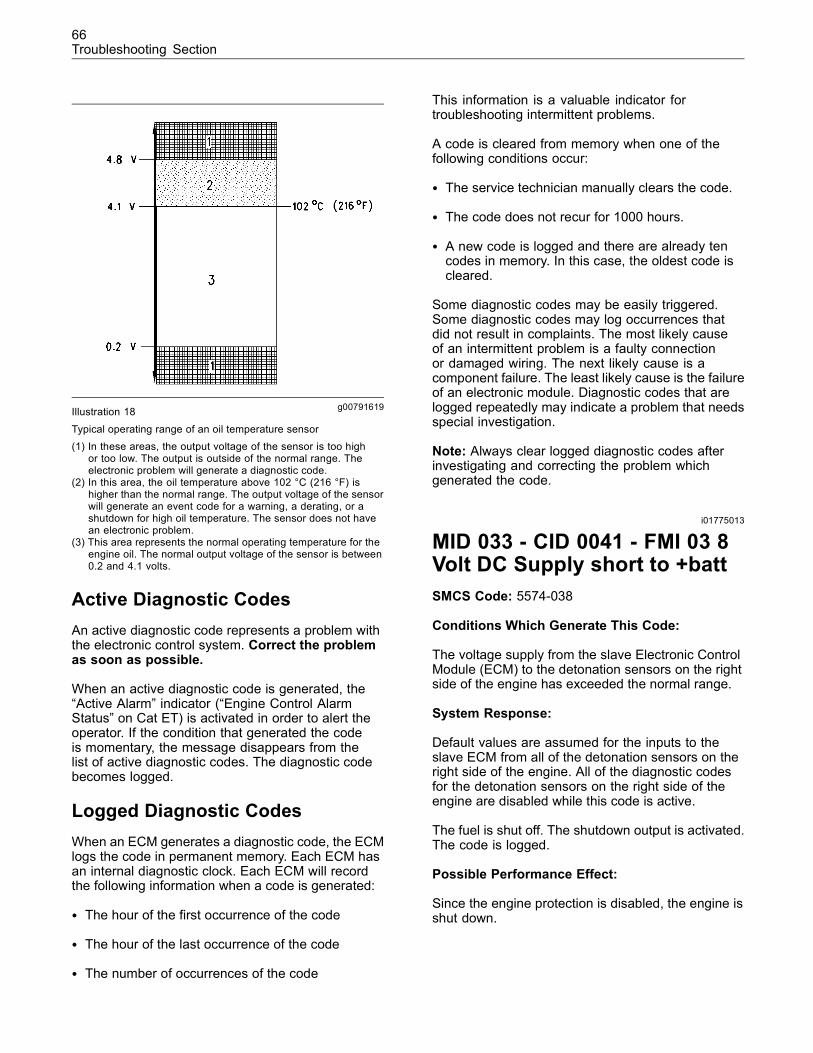
66Troubleshooting Section
g00791619Illustration 18
Typical operating range of an oil temperature sensor(1) In these areas, the output voltage of the sensor is too high
or too low. The output is outside of the normal range. Theelectronic problem will generate a diagnostic code.
(2) In this area, the oil temperature above 102 °C (216 °F) ishigher than the normal range. The output voltage of the sensorwill generate an event code for a warning, a derating, or ashutdown for high oil temperature. The sensor does not havean electronic problem.
(3) This area represents the normal operating temperature for theengine oil. The normal output voltage of the sensor is between0.2 and 4.1 volts.
Active Diagnostic CodesAn active diagnostic code represents a problem withthe electronic control system. Correct the problemas soon as possible.
When an active diagnostic code is generated, the“Active Alarm” indicator (“Engine Control AlarmStatus” on Cat ET) is activated in order to alert theoperator. If the condition that generated the codeis momentary, the message disappears from thelist of active diagnostic codes. The diagnostic codebecomes logged.
Logged Diagnostic CodesWhen an ECM generates a diagnostic code, the ECMlogs the code in permanent memory. Each ECM hasan internal diagnostic clock. Each ECM will recordthe following information when a code is generated:
• The hour of the first occurrence of the code
• The hour of the last occurrence of the code
• The number of occurrences of the code
This information is a valuable indicator fortroubleshooting intermittent problems.
A code is cleared from memory when one of thefollowing conditions occur:
• The service technician manually clears the code.
• The code does not recur for 1000 hours.
• A new code is logged and there are already tencodes in memory. In this case, the oldest code iscleared.
Some diagnostic codes may be easily triggered.Some diagnostic codes may log occurrences thatdid not result in complaints. The most likely causeof an intermittent problem is a faulty connectionor damaged wiring. The next likely cause is acomponent failure. The least likely cause is the failureof an electronic module. Diagnostic codes that arelogged repeatedly may indicate a problem that needsspecial investigation.
Note: Always clear logged diagnostic codes afterinvestigating and correcting the problem whichgenerated the code.
i01775013
MID 033 - CID 0041 - FMI 03 8Volt DC Supply short to +battSMCS Code: 5574-038
Conditions Which Generate This Code:
The voltage supply from the slave Electronic ControlModule (ECM) to the detonation sensors on the rightside of the engine has exceeded the normal range.
System Response:
Default values are assumed for the inputs to theslave ECM from all of the detonation sensors on theright side of the engine. All of the diagnostic codesfor the detonation sensors on the right side of theengine are disabled while this code is active.
The fuel is shut off. The shutdown output is activated.The code is logged.
Possible Performance Effect:
Since the engine protection is disabled, the engine isshut down.
67Troubleshooting Section
Troubleshooting:
Perform the following diagnostic procedure: “+8VSensor Voltage Supply”
Results:
• OK – STOP.
i01775014
MID 033 - CID 0041 - FMI 04 8Volt DC Supply short to groundSMCS Code: 5574-038
Conditions Which Generate This Code:
The voltage supply from the slave Electronic ControlModule (ECM) to the detonation sensors on the rightside of the engine is below the normal range.
System Response:
Default values are assumed for the inputs to theslave ECM from all of the detonation sensors on theright side of the engine. All of the diagnostic codesfor the detonation sensors on the right side of theengine are disabled while this code is active.
The fuel is shut off. The shutdown output is activated.The code is logged.
Possible Performance Effect:
Since the engine protection is disabled, the engine isshut down.
Troubleshooting:
Perform the following diagnostic procedure: “+8VSensor Voltage Supply”
Results:
• OK – STOP.
i01935325
MID 033 - CID 0168 -FMI 02 System Voltageintermittent/erraticSMCS Code: 1408-038
Conditions Which Generate This Code:
The slave Electronic Control Module (ECM) has beenpowered for at least 5 seconds. The engine has beenrunning. Either of the following conditions occur:
• The power supply voltage is less than 6 VDC fora minimum of 0.060 seconds. The power supplyvoltage returns to the normal range within 0.015seconds.
• There are three voltage readings of less than 6VDC within 7 seconds.
System Response:
The alarm output is activated. The code is logged.
Note: If power supply voltage is lost and the voltagedoes not return, the slave ECM will not log thisdiagnostic code. The engine will shut down.
Possible Performance Effect:
The intermittent problem may not affect engineoperation. However, the engine may experiencespeed burps, intermittent shutdowns, and/orcomplete shutdowns.
Perform the following diagnostic procedure:“Electrical Power Supply”
Results:
• OK – STOP.
i01769134
MID 033 - CID 0301 - FMI 05Ignition Transformer Primary#1 open circuitSMCS Code: 1561-038
Conditions Which Generate This Code:
The primary circuit of the transformer is diagnosedwith an open circuit.
System Response:
The alarm output is activated. The code is logged.
Possible Performance Effect:
The cylinder will misfire.
Troubleshooting:
One of the following conditions is the source of thediagnostic code:
• A broken circuit driver’s wire for the transformer
• A broken return wire for the transformer
68Troubleshooting Section
• An open circuit within the primary winding of thetransformer
• An internal failure of the slave electronic controlmodule (ECM)
Perform the following diagnostic procedure: “IgnitionTransformers Primary Circuit”
Results:
• OK – STOP.
i01758737
MID 033 - CID 0301 - FMI 06Ignition Transformer Primary#1 shortSMCS Code: 1561-038
Conditions Which Generate This Code:
The path for the circuit driver of the transformer isdiagnosed with a short circuit.
System Response:
The alarm output is activated. The code is logged.
Possible Performance Effect:
The cylinder will misfire.
Troubleshooting:
One of the following conditions is the source of thediagnostic code:
• A short circuit in the wiring from the slave ElectronicControl Module (ECM) to the transformer
• A short circuit within the primary winding of thetransformer
• An internal failure of the slave ECM
Perform the following diagnostic procedure: “IgnitionTransformers Primary Circuit”
Results:
• OK – STOP.
i01758839
MID 033 - CID 0303 - FMI 05Ignition Transformer Primary#3 open circuitSMCS Code: 1561-038
Conditions Which Generate This Code:
The primary circuit of the transformer is diagnosedwith an open circuit.
System Response:
The alarm output is activated. The code is logged.
Possible Performance Effect:
The cylinder will misfire.
Troubleshooting:
One of the following conditions is the source of thediagnostic code:
• An open circuit in the wiring from the slaveElectronic Control Module (ECM) to thetransformer
• An open circuit within the primary winding of thetransformer
• An internal failure of the slave ECM
Perform the following diagnostic procedure: “IgnitionTransformers Primary Circuit”
Results:
• OK – STOP.
i01758841
MID 033 - CID 0303 - FMI 06Ignition Transformer Primary#3 shortSMCS Code: 1561-038
Conditions Which Generate This Code:
The path for the circuit driver of the transformer isdiagnosed with a short circuit.
System Response:
The alarm output is activated. The code is logged.

69Troubleshooting Section
Possible Performance Effect:
The cylinder will misfire.
Troubleshooting:
One of the following conditions is the source of thediagnostic code:
• A short circuit in the wiring from the slave ElectronicControl Module (ECM) to the transformer
• A short circuit within the primary winding of thetransformer
• An internal failure of the slave ECM
Perform the following diagnostic procedure: “IgnitionTransformers Primary Circuit”
Results:
• OK – STOP.
i01758846
MID 033 - CID 0305 - FMI 05Ignition Transformer Primary#5 open circuitSMCS Code: 1561-038
Conditions Which Generate This Code:
The primary circuit of the transformer is diagnosedwith an open circuit.
System Response:
The alarm output is activated. The code is logged.
Possible Performance Effect:
The cylinder will misfire.
Troubleshooting:
One of the following conditions is the source of thediagnostic code:
• An open circuit in the wiring from the slaveElectronic Control Module (ECM) to thetransformer
• An open circuit within the primary winding of thetransformer
• An internal failure of the slave ECM
Perform the following diagnostic procedure: “IgnitionTransformers Primary Circuit”
Results:
• OK – STOP.
i01758849
MID 033 - CID 0305 - FMI 06Ignition Transformer Primary#5 shortSMCS Code: 1561-038
Conditions Which Generate This Code:
The path for the circuit driver of the transformer isdiagnosed with a short circuit.
System Response:
The alarm output is activated. The code is logged.
Possible Performance Effect:
The cylinder will misfire.
Troubleshooting:
One of the following conditions is the source of thediagnostic code:
• A short circuit in the wiring from the slave ElectronicControl Module (ECM) to the transformer
• A short circuit within the primary winding of thetransformer
• An internal failure of the slave ECM
Perform the following diagnostic procedure: “IgnitionTransformers Primary Circuit”
Results:
• OK – STOP.
i01758852
MID 033 - CID 0307 - FMI 05Ignition Transformer Primary#7 open circuitSMCS Code: 1561-038
Conditions Which Generate This Code:
The primary circuit of the transformer is diagnosedwith an open circuit.
70Troubleshooting Section
System Response:
The alarm output is activated. The code is logged.
Possible Performance Effect:
The cylinder will misfire.
Troubleshooting:
One of the following conditions is the source of thediagnostic code:
• An open circuit in the wiring from the slaveElectronic Control Module (ECM) to thetransformer
• An open circuit within the primary winding of thetransformer
• An internal failure of the slave ECM
Perform the following diagnostic procedure: “IgnitionTransformers Primary Circuit”
Results:
• OK – STOP.
i01758853
MID 033 - CID 0307 - FMI 06Ignition Transformer Primary#7 shortSMCS Code: 1561-038
Conditions Which Generate This Code:
The path for the circuit driver of the transformer isdiagnosed with a short circuit.
System Response:
The alarm output is activated. The code is logged.
Possible Performance Effect:
The cylinder will misfire.
Troubleshooting:
One of the following conditions is the source of thediagnostic code:
• A short circuit in the wiring between the slaveElectronic Control Module (ECM) and thetransformer
• A short circuit within the primary winding of thetransformer
• An internal failure of the slave ECM
Perform the following diagnostic procedure: “IgnitionTransformers Primary Circuit”
Results:
• OK – STOP.
i01758859
MID 033 - CID 0309 - FMI 05Ignition Transformer Primary#9 open circuitSMCS Code: 1561-038
Conditions Which Generate This Code:
The primary circuit of the transformer is diagnosedwith an open circuit.
System Response:
The alarm output is activated. The code is logged.
Possible Performance Effect:
The cylinder will misfire.
Troubleshooting:
One of the following conditions is the source of thediagnostic code:
• An open circuit in the wiring from the slaveElectronic Control Module (ECM) to thetransformer
• An open circuit within the primary winding of thetransformer
• An internal failure of the slave ECM
Perform the following diagnostic procedure: “IgnitionTransformers Primary Circuit”
Results:
• OK – STOP.
71Troubleshooting Section
i01758861
MID 033 - CID 0309 - FMI 06Ignition Transformer Primary#9 shortSMCS Code: 1561-038
Conditions Which Generate This Code:
The path for the circuit driver of the transformer isdiagnosed with a short circuit.
System Response:
The alarm output is activated. The code is logged.
Possible Performance Effect:
The cylinder will misfire.
Troubleshooting:
One of the following conditions is the source of thediagnostic code:
• A short circuit in the wiring between the slaveElectronic Control Module (ECM) and thetransformer
• A short circuit within the primary winding of thetransformer
• An internal failure of the slave ECM
Perform the following diagnostic procedure: “IgnitionTransformers Primary Circuit”
Results:
• OK – STOP.
i01758872
MID 033 - CID 0311 - FMI 05Ignition Transformer Primary#11 open circuitSMCS Code: 1561-038
Conditions Which Generate This Code:
The primary circuit of the transformer is diagnosedwith an open circuit.
System Response:
The alarm output is activated. The code is logged.
Possible Performance Effect:
The cylinder will misfire.
Troubleshooting:
One of the following conditions is the source of thediagnostic code:
• An open circuit in the wiring from the slaveElectronic Control Module (ECM) to thetransformer
• An open circuit within the primary winding of thetransformer
• An internal failure of the slave ECM
Perform the following diagnostic procedure: “IgnitionTransformers Primary Circuit”
Results:
• OK – STOP.
i01758875
MID 033 - CID 0311 - FMI 06Ignition Transformer Primary#11 shortSMCS Code: 1561-038
Conditions Which Generate This Code:
The path for the circuit driver of the transformer isdiagnosed with a short circuit.
System Response:
The alarm output is activated. The code is logged.
Possible Performance Effect:
The cylinder will misfire.
Troubleshooting:
One of the following conditions is the source of thediagnostic code:
• A short circuit in the wiring between the slaveElectronic Control Module (ECM) and thetransformer
• A short circuit within the primary winding of thetransformer
72Troubleshooting Section
• An internal failure of the slave ECM
Perform the following diagnostic procedure: “IgnitionTransformers Primary Circuit”
Results:
• OK – STOP.
i01758886
MID 033 - CID 0313 - FMI 05Ignition Transformer Primary#13 open circuitSMCS Code: 1561-038
Conditions Which Generate This Code:
The primary circuit of the transformer is diagnosedwith an open circuit.
System Response:
The alarm output is activated. The code is logged.
Possible Performance Effect:
The cylinder will misfire.
Troubleshooting:
One of the following conditions is the source of thediagnostic code:
• An open circuit in the wiring from the slaveElectronic Control Module (ECM) to thetransformer
• An open circuit within the primary winding of thetransformer
• An internal failure of the slave ECM
Perform the following diagnostic procedure: “IgnitionTransformers Primary Circuit”
Results:
• OK – STOP.
i01758889
MID 033 - CID 0313 - FMI 06Ignition Transformer Primary#13 shortSMCS Code: 1561-038
Conditions Which Generate This Code:
The path for the circuit driver of the transformer isdiagnosed with a short circuit.
System Response:
The alarm output is activated. The code is logged.
Possible Performance Effect:
The cylinder will misfire.
Troubleshooting:
One of the following conditions is the source of thediagnostic code:
• A short circuit in the wiring between the slaveElectronic Control Module (ECM) and thetransformer
• A short circuit within the primary winding of thetransformer
• An internal failure of the slave ECM
Perform the following diagnostic procedure: “IgnitionTransformers Primary Circuit”
Results:
• OK – STOP.
i01758898
MID 033 - CID 0315 - FMI 05Ignition Transformer Primary#15 open circuitSMCS Code: 1561-038
Conditions Which Generate This Code:
The primary circuit of the transformer is diagnosedwith an open circuit.
System Response:
The alarm output is activated. The code is logged.
73Troubleshooting Section
Possible Performance Effect:
The cylinder will misfire.
Troubleshooting:
One of the following conditions is the source of thediagnostic code:
• An open circuit in the wiring from the slaveElectronic Control Module (ECM) to thetransformer
• An open circuit within the primary winding of thetransformer
• An internal failure of the slave ECM
Perform the following diagnostic procedure: “IgnitionTransformers Primary Circuit”
Results:
• OK – STOP.
i01758902
MID 033 - CID 0315 - FMI 06Ignition Transformer Primary#15 shortSMCS Code: 1561-038
Conditions Which Generate This Code:
The path for the circuit driver of the transformer isdiagnosed with a short circuit.
System Response:
The alarm output is activated. The code is logged.
Possible Performance Effect:
The cylinder will misfire.
Troubleshooting:
One of the following conditions is the source of thediagnostic code:
• A short circuit in the wiring between the slaveElectronic Control Module (ECM) and thetransformer
• A short circuit within the primary winding of thetransformer
• An internal failure of the slave ECM
Perform the following diagnostic procedure: “IgnitionTransformers Primary Circuit”
Results:
• OK – STOP.
i01775725
MID 033 - CID 0320 - FMI 03Speed/Timing Sensor short to+battSMCS Code: 1912-038
Conditions Which Generate This Code:
To activate this code, all of the following conditionsmust occur:
The slave Electronic Control Module (ECM) hasbeen powered for at least one second. The patternof the timing reference gear is lost for more than onesecond. The engine speed is greater than 150 rpm.Neither of the following diagnostic codes are active:
• 145 - 03 12 Volt DC Power Supply short to +batt
• 145 - 04 12 Volt DC Power Supply short to ground
Note: The 0320 - 03 code is set after the pattern ofthe timing reference gear is lost for more than onesecond. However, the logic hesitates for 1.5 secondsbefore the code is activated. If a 145 - 03 or 145 - 04is activated during the 1.5 seconds, then the 0320 -03 code is deactivated.
System Response:
If the engine is running, the ignition signals stop. Theshutdown output is activated. The code is logged.
Possible Performance Effect:
If the engine is running, the engine will be shut down.If the engine is not running, the engine will not start.
Troubleshooting:
Perform the following diagnostic procedure: “EngineSpeed/Timing Sensor”
Results:
• OK – STOP.
74Troubleshooting Section
i01775729
MID 033 - CID 0320 - FMI 08Engine Speed/Timing signalabnormalSMCS Code: 1912-038
Conditions Which Generate This Code:
The slave Electronic Control Module (ECM) must bepowered for at least one second. The engine speedis greater than 150 rpm. One of the following twoconditions occurs:
• An invalid pattern for the timing reference gearis detected. For example, reverse rotation isdetected.
• The pattern for the timing reference gear is lost forless than one second.
System Response:
If the engine is running, the ignition signals stop. Theshutdown output is activated. The code is logged.
Possible Performance Effect:
If the engine is running, the engine will be shut down.If the engine is not running, the engine will not start.
Troubleshooting:
Perform the following diagnostic procedure: “EngineSpeed/Timing Sensor”
Results:
• OK – STOP.
i01864730
MID 033 - CID 0401 - FMI05 Ignition TransformerSecondary #1 open circuitSMCS Code: 1561-038
Conditions Which Generate This Code:
The transformer’s secondary circuit is diagnosed withan open circuit.
System Response:
The status of the transformer’s secondary output isset to 120 percent. The alarm output is activated andthe code is logged.
Possible Performance Effect:
The cylinder will misfire.
Troubleshooting:
One of the following conditions is the source of thediagnostic code:
• A problem with the transformer’s ground
• An open circuit within the secondary winding ofthe transformer
• A problem with the connection to the spark plug’sterminal post
• The spark plug has internal damage or an opencircuit.
• The spark plug gap is too wide.
Perform the following diagnostic procedure: “IgnitionTransformers Secondary Circuit and Spark Plugs”
Results:
• OK – STOP.
i01864793
MID 033 - CID 0401 - FMI06 Ignition TransformerSecondary #1 short to groundSMCS Code: 1561-038
Conditions Which Generate This Code:
The transformer’s secondary circuit is diagnosed witha short circuit.
System Response:
The status of the transformer’s secondary output isset to zero percent. The alarm output is activated andthe code is logged.
Possible Performance Effect:
The cylinder will misfire.
Troubleshooting:
One of the following conditions is the source of thediagnostic code:
• A short circuit within the secondary winding of thetransformer
75Troubleshooting Section
• The spark plug is fouled.
• The spark plug gap is closed.
Perform the following diagnostic procedure: “IgnitionTransformers Secondary Circuit and Spark Plugs”
Results:
• OK – STOP.
i01864795
MID 033 - CID 0403 - FMI05 Ignition TransformerSecondary #3 open circuitSMCS Code: 1561-038
Conditions Which Generate This Code:
The transformer’s secondary circuit is diagnosed withan open circuit.
System Response:
The status of the transformer’s secondary output isset to 120 percent. The alarm output is activated andthe code is logged.
Possible Performance Effect:
The cylinder will misfire.
Troubleshooting:
One of the following conditions is the source of thediagnostic code:
• A problem with the transformer’s ground
• An open circuit within the secondary winding ofthe transformer
• A problem with the connection to the spark plug’sterminal post
• The spark plug has internal damage or an opencircuit.
• The spark plug gap is too wide.
Perform the following diagnostic procedure: “IgnitionTransformers Secondary Circuit and Spark Plugs”
Results:
• OK – STOP.
i01864797
MID 033 - CID 0403 - FMI06 Ignition TransformerSecondary #3 short to groundSMCS Code: 1561-038
Conditions Which Generate This Code:
The transformer’s secondary circuit is diagnosed witha short circuit.
System Response:
The status of the transformer’s secondary output isset to zero percent. The alarm output is activated andthe code is logged.
Possible Performance Effect:
The cylinder will misfire.
Troubleshooting:
One of the following conditions is the source of thediagnostic code:
• A short circuit within the secondary winding of thetransformer
• The spark plug is fouled.
• The spark plug gap is closed.
Perform the following diagnostic procedure: “IgnitionTransformers Secondary Circuit and Spark Plugs”
Results:
• OK – STOP.
i01864798
MID 033 - CID 0405 - FMI05 Ignition TransformerSecondary #5 open circuitSMCS Code: 1561-038
Conditions Which Generate This Code:
The transformer’s secondary circuit is diagnosed withan open circuit.
System Response:
The status of the transformer’s secondary output isset to 120 percent. The alarm output is activated andthe code is logged.
76Troubleshooting Section
Possible Performance Effect:
Generation of the diagnostic code does not affectengine performance. However, the engine willprobably misfire. This will cause the engine to runrough. The engine may shut down.
Troubleshooting:
One of the following conditions is the source of thediagnostic code:
• A problem with the transformer’s ground
• An open circuit within the secondary winding ofthe transformer
• A problem with the connection to the spark plug’sterminal post
• The spark plug has internal damage or an opencircuit.
• The spark plug gap is too wide.
Perform the following diagnostic procedure: “IgnitionTransformers Secondary Circuit and Spark Plugs”
Results:
• OK – STOP.
i01864800
MID 033 - CID 0405 - FMI06 Ignition TransformerSecondary #5 short to groundSMCS Code: 1561-038
Conditions Which Generate This Code:
The transformer’s secondary circuit is diagnosed witha short circuit.
System Response:
The status of the transformer’s secondary output isset to zero percent. The alarm output is activated andthe code is logged.
Possible Performance Effect:
The cylinder will misfire.
Troubleshooting:
One of the following conditions is the source of thediagnostic code:
• A short circuit within the secondary winding of thetransformer
• The spark plug is fouled.
• The spark plug gap is closed.
Perform the following diagnostic procedure: “IgnitionTransformers Secondary Circuit and Spark Plugs”
Results:
• OK – STOP.
i01864802
MID 033 - CID 0407 - FMI05 Ignition TransformerSecondary #7 open circuitSMCS Code: 1561-038
Conditions Which Generate This Code:
The transformer’s secondary circuit is diagnosed withan open circuit.
System Response:
The status of the transformer’s secondary output isset to 120 percent. The alarm output is activated andthe code is logged.
Possible Performance Effect:
The cylinder will misfire.
Troubleshooting:
One of the following conditions is the source of thediagnostic code:
• A problem with the transformer’s ground
• An open circuit within the secondary winding ofthe transformer
• A problem with the connection to the spark plug’sterminal post
• The spark plug has internal damage or an opencircuit.
• The spark plug gap is too wide.
Perform the following diagnostic procedure: “IgnitionTransformers Secondary Circuit and Spark Plugs”
77Troubleshooting Section
Results:
• OK – STOP.
i01864806
MID 033 - CID 0407 - FMI06 Ignition TransformerSecondary #7 short to groundSMCS Code: 1561-038
Conditions Which Generate This Code:
The transformer’s secondary circuit is diagnosed witha short circuit.
System Response:
The status of the transformer’s secondary output isset to zero percent. The alarm output is activated andthe code is logged.
Possible Performance Effect:
The cylinder will misfire.
Troubleshooting:
One of the following conditions is the source of thediagnostic code:
• A short circuit within the secondary winding of thetransformer
• The spark plug is fouled.
• The spark plug gap is closed.
Perform the following diagnostic procedure: “IgnitionTransformers Secondary Circuit and Spark Plugs”
Results:
• OK – STOP.
i01864809
MID 033 - CID 0409 - FMI05 Ignition TransformerSecondary #9 open circuitSMCS Code: 1561-038
Conditions Which Generate This Code:
The transformer’s secondary circuit is diagnosed withan open circuit.
System Response:
The status of the transformer’s secondary output isset to 120 percent. The alarm output is activated andthe code is logged.
Possible Performance Effect:
The cylinder will misfire.
Troubleshooting:
One of the following conditions is the source of thediagnostic code:
• A problem with the transformer’s ground
• An open circuit within the secondary winding ofthe transformer
• A problem with the connection to the spark plug’sterminal post
• The spark plug has internal damage or an opencircuit.
• The spark plug gap is too wide.
Perform the following diagnostic procedure: “IgnitionTransformers Secondary Circuit and Spark Plugs”
Results:
• OK – STOP.
i01864812
MID 033 - CID 0409 - FMI06 Ignition TransformerSecondary #9 short to groundSMCS Code: 1561-038
Conditions Which Generate This Code:
The transformer’s secondary circuit is diagnosed witha short circuit.
System Response:
The status of the transformer’s secondary output isset to zero percent. The alarm output is activated andthe code is logged.
Possible Performance Effect:
The cylinder will misfire.
78Troubleshooting Section
Troubleshooting:
One of the following conditions is the source of thediagnostic code:
• A short circuit within the secondary winding of thetransformer
• The spark plug is fouled.
• The spark plug gap is closed.
Perform the following diagnostic procedure: “IgnitionTransformers Secondary Circuit and Spark Plugs”
Results:
• OK – STOP.
i01864818
MID 033 - CID 0411 - FMI05 Ignition TransformerSecondary #11 open circuitSMCS Code: 1561-038
Conditions Which Generate This Code:
The transformer’s secondary circuit is diagnosed withan open circuit.
System Response:
The status of the transformer’s secondary output isset to 120 percent. The alarm output is activated andthe code is logged.
Possible Performance Effect:
The cylinder will misfire.
Troubleshooting:
One of the following conditions is the source of thediagnostic code:
• A problem with the transformer’s ground
• An open circuit within the secondary winding ofthe transformer
• A problem with the connection to the spark plug’sterminal post
• The spark plug has internal damage or an opencircuit.
• The spark plug gap is too wide.
Perform the following diagnostic procedure: “IgnitionTransformers Secondary Circuit and Spark Plugs”
Results:
• OK – STOP.
i01864821
MID 033 - CID 0411 - FMI06 Ignition TransformerSecondary #11 short to groundSMCS Code: 1561-038
Conditions Which Generate This Code:
The transformer’s secondary circuit is diagnosed witha short circuit.
System Response:
The status of the transformer’s secondary output isset to zero percent. The alarm output is activated andthe code is logged.
Possible Performance Effect:
The cylinder will misfire.
Troubleshooting:
One of the following conditions is the source of thediagnostic code:
• A short circuit within the secondary winding of thetransformer
• The spark plug is fouled.
• The spark plug gap is closed.
Perform the following diagnostic procedure: “IgnitionTransformers Secondary Circuit and Spark Plugs”
Results:
• OK – STOP.
79Troubleshooting Section
i01864822
MID 033 - CID 0413 - FMI05 Ignition TransformerSecondary #13 open circuitSMCS Code: 1561-038
Conditions Which Generate This Code:
The transformer’s secondary circuit is diagnosed withan open circuit.
System Response:
The status of the transformer’s secondary output isset to 120 percent. The alarm output is activated andthe code is logged.
Possible Performance Effect:
The cylinder will misfire.
Troubleshooting:
One of the following conditions is the source of thediagnostic code:
• A problem with the transformer’s ground
• An open circuit within the secondary winding ofthe transformer
• A problem with the connection to the spark plug’sterminal post
• The spark plug has internal damage or an opencircuit.
• The spark plug gap is too wide.
Perform the following diagnostic procedure: “IgnitionTransformers Secondary Circuit and Spark Plugs”
Results:
• OK – STOP.
i01864824
MID 033 - CID 0413 - FMI06 Ignition TransformerSecondary #13 short to groundSMCS Code: 1561-038
Conditions Which Generate This Code:
The transformer’s secondary circuit is diagnosed witha short circuit.
System Response:
The status of the transformer’s secondary output isset to zero percent. The alarm output is activated andthe code is logged.
Possible Performance Effect:
The cylinder will misfire.
Troubleshooting:
One of the following conditions is the source of thediagnostic code:
• A short circuit within the secondary winding of thetransformer
• The spark plug is fouled.
• The spark plug gap is closed.
Perform the following diagnostic procedure: “IgnitionTransformers Secondary Circuit and Spark Plugs”
Results:
• OK – STOP.
i01864826
MID 033 - CID 0415 - FMI05 Ignition TransformerSecondary #15 open circuitSMCS Code: 1561-038
Conditions Which Generate This Code:
The transformer’s secondary circuit is diagnosed withan open circuit.
System Response:
The status of the transformer’s secondary output isset to 120 percent. The alarm output is activated andthe code is logged.
Possible Performance Effect:
The cylinder will misfire.
Troubleshooting:
One of the following conditions is the source of thediagnostic code:
• A problem with the transformer’s ground
• An open circuit within the secondary winding ofthe transformer
80Troubleshooting Section
• A problem with the connection to the spark plug’sterminal post
• The spark plug has internal damage or an opencircuit.
• The spark plug gap is too wide.
Perform the following diagnostic procedure: “IgnitionTransformers Secondary Circuit and Spark Plugs”
Results:
• OK – STOP.
i01864829
MID 033 - CID 0415 - FMI06 Ignition TransformerSecondary #15 short to groundSMCS Code: 1561-038
Conditions Which Generate This Code:
The transformer’s secondary circuit is diagnosed witha short circuit.
System Response:
The status of the transformer’s secondary output isset to zero percent. The alarm output is activated andthe code is logged.
Possible Performance Effect:
The cylinder will misfire.
Troubleshooting:
One of the following conditions is the source of thediagnostic code:
• A short circuit within the secondary winding of thetransformer
• The spark plug is fouled.
• The spark plug gap is closed.
Perform the following diagnostic procedure: “IgnitionTransformers Secondary Circuit and Spark Plugs”
Results:
• OK – STOP.
i01796190
MID 033 - CID 0590 - FMI 09Unable to communicate withEngine ECMSMCS Code: 1901-038
Conditions Which Generate This Code:
The master Electronic Control Module (ECM) hassent ten consecutive messages to the slave ECM viathe Cat data link. None of the messages have beenreceived by the slave ECM. Alternatively, the masterECM has sent messages to the slave ECM over aperiod of time, and two-thirds of the messages havenot been received by the slave ECM. Neither ECM isbeing flashed.
Note: Although there is a failure to communicatewith the slave ECM, the master ECM may still beable to communicate with the Caterpillar ElectronicTechnician (ET).
System Response:
The alarm output is activated.
The code is logged by the slave ECM.
Engine ignition is terminated.
Note: If Cat ET cannot communicate with the masterECM, the values will display “Unavailable”.
Possible Performance Effect:
The engine is shut down.
Perform the following diagnostic procedure: “CatData Link”
Results:
• OK – STOP.
81Troubleshooting Section
i01761131
MID 033 - CID 1501 - FMI 03Cylinder #1 Detonation Sensoropen/short to +battSMCS Code: 1559-038
Conditions Which Generate This Code:
The run relay and the crank terminate relay areenergized. The signal from the detonation sensorfor cylinders 1 and 3 to the slave Electronic ControlModule (ECM) is greater than 4.8 VDC for tenseconds.
Neither of the following diagnostic codes are active:
• 0041 - 03 8 Volt DC Supply short to +batt
• 0041 - 04 8 Volt DC Supply short to ground
System Response:
The shutdown output is activated. The code is logged.
Possible Performance Effect:
The engine is shut down.
Troubleshooting:
Perform the following diagnostic procedure:“Detonation Sensors”
Results:
• OK – STOP.
i01761136
MID 033 - CID 1501 - FMI 04Cylinder #1 Detonation Sensorshort to groundSMCS Code: 1559-038
Conditions Which Generate This Code:
The run relay and the crank terminate relay areenergized. The signal from the detonation sensorfor cylinders 1 and 3 to the slave Electronic ControlModule (ECM) is less than 1.0 VDC for ten seconds.
Neither of the following diagnostic codes are active:
• 0041 - 03 8 Volt DC Supply short to +batt
• 0041 - 04 8 Volt DC Supply short to ground
System Response:
The shutdown output is activated. The code is logged.
Possible Performance Effect:
The engine is shut down.
Troubleshooting:
Perform the following diagnostic procedure:“Detonation Sensors”
Results:
• OK – STOP.
i01761195
MID 033 - CID 1505 - FMI 03Cylinder #5 Detonation Sensoropen/short to +battSMCS Code: 1559-038
Conditions Which Generate This Code:
The run relay and the crank terminate relay areenergized. The signal from the detonation sensorfor cylinders 5 and 7 to the slave Electronic ControlModule (ECM) is greater than 4.8 VDC for tenseconds.
Neither of the following diagnostic codes are active:
• 0041 - 03 8 Volt DC Supply short to +batt
• 0041 - 04 8 Volt DC Supply short to ground
System Response:
The shutdown output is activated. The code is logged.
Possible Performance Effect:
The engine is shut down.
Troubleshooting:
Perform the following diagnostic procedure:“Detonation Sensors”
Results:
• OK – STOP.
82Troubleshooting Section
i01761200
MID 033 - CID 1505 - FMI 04Cylinder #5 Detonation Sensorshort to groundSMCS Code: 1559-038
Conditions Which Generate This Code:
The run relay and the crank terminate relay areenergized. The signal from the detonation sensorfor cylinders 5 and 7 to the slave Electronic ControlModule (ECM) is less than 1.0 VDC for ten seconds.
Neither of the following diagnostic codes are active:
• 0041 - 03 8 Volt DC Supply short to +batt
• 0041 - 04 8 Volt DC Supply short to ground
System Response:
The shutdown output is activated. The code is logged.
Possible Performance Effect:
The engine is shut down.
Troubleshooting:
Perform the following diagnostic procedure:“Detonation Sensors”
Results:
• OK – STOP.
i01761212
MID 033 - CID 1509 - FMI 03Cylinder #9 Detonation Sensoropen/short to +battSMCS Code: 1559-038
Conditions Which Generate This Code:
The run relay and the crank terminate relay areenergized. The signal from the detonation sensor forcylinders 9 and 11 to the slave Electronic ControlModule (ECM) is greater than 4.8 VDC for tenseconds.
Neither of the following diagnostic codes are active:
• 0041 - 03 8 Volt DC Supply short to +batt
• 0041 - 04 8 Volt DC Supply short to ground
System Response:
The shutdown output is activated. The code is logged.
Possible Performance Effect:
The engine is shut down.
Troubleshooting:
Perform the following diagnostic procedure:“Detonation Sensors”
Results:
• OK – STOP.
i01761215
MID 033 - CID 1509 - FMI 04Cylinder #9 Detonation Sensorshort to groundSMCS Code: 1559-038
Conditions Which Generate This Code:
The run relay and the crank terminate relay areenergized. The signal from the detonation sensor forcylinders 9 and 11 to the slave Electronic ControlModule (ECM) is less than 1.0 VDC for ten seconds.
Neither of the following diagnostic codes are active:
• 0041 - 03 8 Volt DC Supply short to +batt
• 0041 - 04 8 Volt DC Supply short to ground
System Response:
The shutdown output is activated. The code is logged.
Possible Performance Effect:
The engine is shut down.
Troubleshooting:
Perform the following diagnostic procedure:“Detonation Sensors”
Results:
• OK – STOP.
83Troubleshooting Section
i01761230
MID 033 - CID 1513 - FMI03 Cylinder #13 DetonationSensor open/short to +battSMCS Code: 1559-038
Conditions Which Generate This Code:
The run relay and the crank terminate relay areenergized. The signal from the detonation sensor forcylinders 13 and 15 to the slave Electronic ControlModule (ECM) is greater than 4.8 VDC for tenseconds.
Neither of the following diagnostic codes are active:
• 0041 - 03 8 Volt DC Supply short to +batt
• 0041 - 04 8 Volt DC Supply short to ground
System Response:
The shutdown output is activated. The code is logged.
Possible Performance Effect:
The engine is shut down.
Troubleshooting:
Perform the following diagnostic procedure:“Detonation Sensors”
Results:
• OK – STOP.
i01761234
MID 033 - CID 1513 - FMI04 Cylinder #13 DetonationSensor short to groundSMCS Code: 1559-038
Conditions Which Generate This Code:
The run relay and the crank terminate relay areenergized. The signal from the detonation sensor forcylinders 13 and 15 to the slave Electronic ControlModule (ECM) is less than 1.0 VDC for ten seconds.
Neither of the following diagnostic codes are active:
• 0041 - 03 8 Volt DC Supply short to +batt
• 0041 - 04 8 Volt DC Supply short to ground
System Response:
The shutdown output is activated. The code is logged.
Possible Performance Effect:
The engine is shut down.
Troubleshooting:
Perform the following diagnostic procedure:“Detonation Sensors”
Results:
• OK – STOP.
i01761242
MID 033 - CID 1517 - FMI03 Cylinder #17 DetonationSensor open/short to +battSMCS Code: 1559-038
Conditions Which Generate This Code:
The run relay and the crank terminate relay areenergized. The signal from the detonation sensor forcylinders 17 and 19 to the slave Electronic ControlModule (ECM) is greater than 4.8 VDC for tenseconds.
Neither of the following diagnostic codes are active:
• 0041 - 03 8 Volt DC Supply short to +batt
• 0041 - 04 8 Volt DC Supply short to ground
System Response:
The shutdown output is activated. The code is logged.
Possible Performance Effect:
The engine is shut down.
Troubleshooting:
Perform the following diagnostic procedure:“Detonation Sensors”
Results:
• OK – STOP.
84Troubleshooting Section
i01761245
MID 033 - CID 1517 - FMI04 Cylinder #17 DetonationSensor short to groundSMCS Code: 1559-038
Conditions Which Generate This Code:
The run relay and the crank terminate relay areenergized. The signal from the detonation sensor forcylinders 17 and 19 to the slave Electronic ControlModule (ECM) is less than 1.0 VDC for ten seconds.
Neither of the following diagnostic codes are active:
• 0041 - 03 8 Volt DC Supply short to +batt
• 0041 - 04 8 Volt DC Supply short to ground
System Response:
The shutdown output is activated. The code is logged.
Possible Performance Effect:
The engine is shut down.
Troubleshooting:
Perform the following diagnostic procedure:“Detonation Sensors”
Results:
• OK – STOP.
i01760803
MID 033 - CID 1748 - FMI05 Ignition TransformerSecondary #17 open circuitSMCS Code: 1561-038
Conditions Which Generate This Code:
The transformer’s secondary circuit is diagnosed withan open circuit.
System Response:
The status of the transformer’s secondary output isset to 120 percent. The alarm output is activated andthe code is logged.
Possible Performance Effect:
The cylinder will misfire.
Troubleshooting:
One of the following conditions is the source of thediagnostic code:
• A problem with the transformer’s ground
• An open circuit within the secondary winding ofthe transformer
• A problem with the connection to the spark plug’sterminal post
• The spark plug has internal damage or an opencircuit.
• The spark plug gap is too wide.
Perform the following diagnostic procedure: “IgnitionTransformers Secondary Circuit and Spark Plugs”
Results:
• OK – STOP.
i01760914
MID 033 - CID 1748 - FMI06 Ignition TransformerSecondary #17 short to groundSMCS Code: 1561-038
Conditions Which Generate This Code:
The transformer’s secondary circuit is diagnosed witha short circuit.
System Response:
The status of the transformer’s secondary output isset to zero percent. The alarm output is activated andthe code is logged.
Possible Performance Effect:
The cylinder will misfire.
Troubleshooting:
One of the following conditions is the source of thediagnostic code:
• A short circuit within the secondary winding of thetransformer
85Troubleshooting Section
• The spark plug is fouled.
• The spark plug gap is closed.
Perform the following diagnostic procedure: “IgnitionTransformers Secondary Circuit and Spark Plugs”
Results:
• OK – STOP.
i01760805
MID 033 - CID 1750 - FMI05 Ignition TransformerSecondary #19 open circuitSMCS Code: 1561-038
Conditions Which Generate This Code:
The transformer’s secondary circuit is diagnosed withan open circuit.
System Response:
The status of the transformer’s secondary output isset to 120 percent. The alarm output is activated andthe code is logged.
Possible Performance Effect:
The cylinder will misfire.
Troubleshooting:
One of the following conditions is the source of thediagnostic code:
• A problem with the transformer’s ground
• An open circuit within the secondary winding ofthe transformer
• A problem with the connection to the spark plug’sterminal post
• The spark plug has internal damage or an opencircuit.
• The spark plug gap is too wide.
Perform the following diagnostic procedure: “IgnitionTransformers Secondary Circuit and Spark Plugs”
Results:
• OK – STOP.
i01760949
MID 033 - CID 1750 - FMI06 Ignition TransformerSecondary #19 short to groundSMCS Code: 1561-038
Conditions Which Generate This Code:
The transformer’s secondary circuit is diagnosed witha short circuit.
System Response:
The status of the transformer’s secondary output isset to zero percent. The alarm output is activated andthe code is logged.
Possible Performance Effect:
The cylinder will misfire.
Troubleshooting:
One of the following conditions is the source of thediagnostic code:
• A short circuit within the secondary winding of thetransformer
• The spark plug is fouled.
• The spark plug gap is closed.
Perform the following diagnostic procedure: “IgnitionTransformers Secondary Circuit and Spark Plugs”
Results:
• OK – STOP.
i01760301
MID 033 - CID 1752 - FMI 05Ignition Transformer Primary#17 open circuitSMCS Code: 1561-038
Conditions Which Generate This Code:
The primary circuit of the transformer is diagnosedwith an open circuit.
System Response:
The alarm output is activated. The code is logged.
86Troubleshooting Section
Possible Performance Effect:
The cylinder will misfire.
Troubleshooting:
One of the following conditions is the source of thediagnostic code:
• An open circuit in the wiring from the slaveElectronic Control Module (ECM) to thetransformer
• An open circuit within the primary winding of thetransformer
• An internal failure of the slave ECM
Perform the following diagnostic procedure: “IgnitionTransformers Primary Circuit”
Results:
• OK – STOP.
i01760305
MID 033 - CID 1752 - FMI 06Ignition Transformer Primary#17 short to groundSMCS Code: 1561-038
Conditions Which Generate This Code:
The path for the circuit driver of the transformer isdiagnosed with a short circuit.
System Response:
The alarm output is activated. The code is logged.
Possible Performance Effect:
The cylinder will misfire.
Troubleshooting:
One of the following conditions is the source of thediagnostic code:
• A short circuit in the wiring between the slaveElectronic Control Module (ECM) and thetransformer
• A short circuit within the primary winding of thetransformer
• An internal failure of the slave ECM
Perform the following diagnostic procedure: “IgnitionTransformers Primary Circuit”
Results:
• OK – STOP.
i01760309
MID 033 - CID 1754 - FMI 05Ignition Transformer Primary#19 open circuitSMCS Code: 1561-038
Conditions Which Generate This Code:
The primary circuit of the transformer is diagnosedwith an open circuit.
System Response:
The alarm output is activated. The code is logged.
Possible Performance Effect:
The cylinder will misfire.
Troubleshooting:
One of the following conditions is the source of thediagnostic code:
• An open circuit in the wiring from the slaveElectronic Control Module (ECM) to thetransformer
• An open circuit within the primary winding of thetransformer
• An internal failure of the slave ECM
Perform the following diagnostic procedure: “IgnitionTransformers Primary Circuit”
Results:
• OK – STOP.
87Troubleshooting Section
i01760311
MID 033 - CID 1754 - FMI 06Ignition Transformer Primary#19 short to groundSMCS Code: 1561-038
Conditions Which Generate This Code:
The path for the circuit driver of the transformer isdiagnosed with a short circuit.
System Response:
The alarm output is activated. The code is logged.
Possible Performance Effect:
The cylinder will misfire.
Troubleshooting:
One of the following conditions is the source of thediagnostic code:
• A short circuit in the wiring between the slaveElectronic Control Module (ECM) and thetransformer
• A short circuit within the primary winding of thetransformer
• An internal failure of the slave ECM
Perform the following diagnostic procedure: “IgnitionTransformers Primary Circuit”
Results:
• OK – STOP.
i02088213
MID 036 - CID 0017 - FMI 05Fuel Shutoff Valve open circuitSMCS Code: 1259-038
Conditions Which Generate This Code:
The master Electronic Control Module (ECM) hasdetected a positive voltage source on the output forthe fuel shutoff valve. The most likely cause is one ofthe following conditions:
• The wiring harness has an open circuit.
• The fuel control relay has an open coil.
• There is a short circuit to the +Battery in the wiringfor the fuel control relay.
Note: This code cannot be detected by the masterECM when the output for the fuel control relay is ON.The output is normally ON when the engine control isin the START mode and the engine RPM is greaterthan zero.
System Response:
No fuel is provided to the engine. The alarm output isactivated. The code is logged.
Possible Performance Effect:
The engine will not start due to the lack of fuel.
Troubleshooting:
The most likely cause is one of the followingconditions:
• An open circuit in the harness or in the fuel controlrelay
• A short circuit to the +Battery in the harness or inthe fuel control relay
Perform the following diagnostic procedure: “ECMOutput Circuit (Fuel Control)”
Results:
• OK – STOP.
i01805813
MID 036 - CID 0017 - FMI 06Fuel Shutoff Valve short togroundSMCS Code: 1259-038
Conditions Which Generate This Code:
• The output for the fuel control relay is ON.
• The master Electronic Control Module (ECM)detects excessive current on the output for thefuel control relay.
Note: This condition cannot be detected by themaster ECM when the output for the fuel control relayis OFF. The output is normally OFF when the enginecontrol is in the STOP mode.
88Troubleshooting Section
System Response:
The master ECM will continue attempting to energizethe relay. The engine may shut down due to a lackof fuel. The alarm output is activated. The code islogged.
Possible Performance Effect:
The engine will not start due to the lack of fuel.
Troubleshooting:
The condition is probably caused by a short circuit inthe harness or by an internal short circuit in the fuelcontrol relay.
Perform the following diagnostic procedure: “ECMOutput Circuit (Fuel Control)”
Results:
• OK – STOP.
i01758598
MID 036 - CID 0017 - FMI 12Fuel Shutoff Valve malfunctionSMCS Code: 1259-038
Conditions Which Generate This Code:
The driver in the master Electronic Control Module(ECM) for the gas shutoff valve is OFF but the enginestill runs.
System Response:
The master ECM will disable the ignition systemand the gas shutoff valve in order to shut down theengine. The shutdown output is activated. The codeis logged.
Possible Performance Effect:
The engine is shut down.
Troubleshooting:
Perform the following diagnostic procedure: “ECMOutput Circuit (Fuel Control)”
Results:
• OK – STOP.
i01914066
MID 036 - CID 0041 - FMI 03 8Volt DC Supply short to +battSMCS Code: 5574-038
Conditions Which Generate This Code:
The voltage supply from the master ElectronicControl Module (ECM) for the 8 volt sensors hasexceeded the normal range.
System Response:
Default values are assumed for the inputs to themaster ECM from all of the 8 volt sensors. All of thediagnostic codes for the 8 volt sensors to the ECMare disabled while this code is active.
The fuel is shut off. The shutdown output is activated.The code is logged.
Possible Performance Effect:
Since the engine protection is disabled, the engine isshut down.
Troubleshooting:
Perform the following diagnostic procedure: “+8VSensor Voltage Supply”
Results:
• OK – STOP.
i01914068
MID 036 - CID 0041 - FMI 04 8Volt DC Supply short to groundSMCS Code: 5574-038
Conditions Which Generate This Code:
The voltage supply from the master ElectronicControl Module (ECM) for the 8 volt sensors is belowthe normal range.
System Response:
Default values are assumed for the inputs to themaster ECM from all of the 8 volt sensors. All of thediagnostic codes for the 8 volt sensors to the ECMare disabled while this code is active.
The fuel is shut off. The shutdown output is activated.The code is logged.
89Troubleshooting Section
Possible Performance Effect:
Since the engine protection is disabled, the engine isshut down.
Troubleshooting:
Perform the following diagnostic procedure: “+8VSensor Voltage Supply”
Results:
• OK – STOP.
i01758614
MID 036 - CID 0100 - FMI03 Engine Oil Pressureopen/short to +battSMCS Code: 1924-038
Conditions Which Generate This Code:
The signal from the filtered oil pressure sensor to themaster Electronic Control Module (ECM) is greaterthan 4.8 VDC for at least five seconds.
Additionally, neither of the following diagnostic codesare active:
• 262 - 03 5 Volt Sensor DC Power Supply short to+batt
• 262 - 04 5 Volt Sensor DC Power Supply short toground
System Response:
The master ECM assumes the last valid value for theengine oil pressure. The monitoring of the oil pressureis disabled. This disables the engine protection forlow oil pressure and for excessive oil pressure.
The fuel is shut off. The shutdown output is activated.The code is logged.
Possible Performance Effect:
Since the engine protection is disabled, the engine isshut down.
Troubleshooting:
This condition indicates an open circuit or a shortcircuit to a positive voltage source.
Perform the following diagnostic procedure: “AnalogSensor Signal”
Results:
• OK – STOP.
i01758623
MID 036 - CID 0100 - FMI 04Engine Oil Pressure short togroundSMCS Code: 1924-038
Conditions Which Generate This Code:
The signal from the filtered oil pressure sensor to themaster Electronic Control Module (ECM) is less than0.2 VDC for at least five seconds.
Additionally, neither of the following diagnostic codesare active:
• 262 - 03 5 Volt Sensor DC Power Supply short to+batt
• 262 - 04 5 Volt Sensor DC Power Supply short toground
System Response:
The master ECM assumes the last valid value for theengine oil pressure. The monitoring of the oil pressureis disabled. This disables the engine protection forlow oil pressure and for excessive oil pressure.
The fuel is shut off. The shutdown output is activated.The code is logged.
Possible Performance Effect:
Since the engine protection is disabled, the engine isshut down.
Troubleshooting:
Perform the following diagnostic procedure: “AnalogSensor Signal”
Results:
• OK – STOP.
90Troubleshooting Section
i01780399
MID 036 - CID 0106 - FMI 03 AirInlet Pressure Sensor short to+battSMCS Code: 5574-038-PX
Conditions Which Generate This Code:
The duty cycle for the inlet manifold pressure sensoris greater than the maximum value.
Additionally, neither of the following diagnostic codesare active:
• 41 - 03 8 Volt DC Supply short to +batt
• 41 - 04 8 Volt DC Supply short to ground
System Response:
The fuel is shut off. The shutdown output is activated.The code is logged.
Possible Performance Effect:
The engine is shut down.
Troubleshooting:
This condition indicates a possible open circuit or apossible short circuit.
Perform the following diagnostic procedure: “PWMSensor”
Results:
• OK – STOP.
i01636377
MID 036 - CID 0106 - FMI 08 AirInlet Pressure Sensor noisysignalSMCS Code: 5574-038-PX
Conditions Which Generate This Code:
The duty cycle or the frequency for the inlet manifoldpressure sensor is out of range.
Additionally, neither of the following diagnostic codesare active:
• 41 - 03 8 Volt DC Supply short to +batt
• 41 - 04 8 Volt DC Supply short to ground
System Response:
The fuel is shut off. The shutdown output is activated.The code is logged.
Possible Performance Effect:
The engine is shut down.
Troubleshooting:
Perform the following diagnostic procedure: “PWMSensor”
Results:
• OK – STOP.
i01793903
MID 036 - CID 0109 - FMI03 Coolant Outlet Pressureopen/short to +battSMCS Code: 5574-038-PX
Conditions Which Generate This Code:
The duty cycle of the pressure sensor for the outlet ofthe engine coolant is greater than the maximum limit.
Additionally, neither of the following diagnostic codesare active:
• 41 - 03 8 Volt DC Supply short to +batt
• 41 - 04 8 Volt DC Supply short to ground
System Response:
The alarm output is activated. The code is logged.
Possible Performance Effect:
The engine performance is not affected.
Troubleshooting:
The condition indicates a possible open circuit or ashort circuit.
Perform the following diagnostic procedure: “PWMSensor”
Results:
• OK – STOP.
91Troubleshooting Section
i01691110
MID 036 - CID 0109 - FMI08 Engine Coolant OutletPressure Sensor noisy signalSMCS Code: 5574-038-PX
Conditions Which Generate This Code:
The duty cycle or the frequency of the signal from thepressure sensor for the outlet of the engine coolantis out of range.
Additionally, neither of the following diagnostic codesare active:
• 41 - 03 8 Volt DC Supply short to +batt
• 41 - 04 8 Volt DC Supply short to ground
System Response:
The alarm output is activated. The code is logged.
Possible Performance Effect:
The engine performance is not affected.
Troubleshooting:
Perform the following diagnostic procedure: “PWMSensor”
Results:
• OK – STOP.
i01758632
MID 036 - CID 0110 - FMI 03Engine Coolant Temperatureopen/short to +battSMCS Code: 1906-038
Conditions Which Generate This Code:
The signal from the engine coolant temperaturesensor to the master Electronic Control Module(ECM) is greater than 4.8 VDC for at least fiveseconds.
System Response:
The master ECM assumes the last valid value forengine coolant temperature. The monitoring of thecoolant temperature is disabled. This disables theengine protection for low coolant temperature and forhigh coolant temperature.
The fuel is shut off. The shutdown output is activated.The code is logged.
Possible Performance Effect:
Since the engine protection is disabled, the engine isshut down.
Troubleshooting:
This condition indicates a possible open circuit or apossible short circuit.
Perform the following diagnostic procedure: “AnalogSensor Signal”
Results:
• OK – STOP.
i01758638
MID 036 - CID 0110 - FMI 04Engine Coolant Temperatureshort to groundSMCS Code: 1906-038
Conditions Which Generate This Code:
The signal from the engine coolant temperaturesensor to the master Electronic Control Module(ECM) is less than 0.2 VDC for at least five seconds.
System Response:
The master ECM assumes the last valid value for theengine coolant temperature. The monitoring of thecoolant temperature is disabled. This disables theengine protection for low coolant temperature and forhigh coolant temperature.
The fuel is shut off. The shutdown output is activated.The code is logged.
Possible Performance Effect:
Since the engine protection is disabled, the engine isshut down.
Troubleshooting:
Perform the following diagnostic procedure: “AnalogSensor Signal”
Results:
• OK – STOP.
92Troubleshooting Section
i01866770
MID 036 - CID 0145 - FMI 03 12Volt DC Power Supply short to+battSMCS Code: 5574-038
Conditions Which Generate This Code:
The master Electronic Control Module (ECM) hasbeen powered for at least five seconds. The 12 voltsensor supply voltage becomes greater than 14.2 Vfor at least one second.
System Response:
If the engine is running, the fuel is shut off. Theshutdown output is activated. The code is logged.
Possible Performance Effect:
The engine is shut down or the engine will not start.
Troubleshooting:
Perform the following diagnostic procedure: “EngineSpeed/Timing Sensor”
Results:
• OK – STOP.
i01866808
MID 036 - CID 0145 - FMI 04 12Volt DC Power Supply short togroundSMCS Code: 5574-038
Conditions Which Generate This Code:
The master Electronic Control Module (ECM) hasbeen powered for at least five seconds. The 12 voltsensor supply voltage becomes less than 11 VDCfor at least one second.
System Response:
If the engine is running, the fuel is shut off. Theshutdown output is activated. The code is logged.
Possible Performance Effect:
The engine is shut down or the engine will not start.
Troubleshooting:
Perform the following diagnostic procedure: “EngineSpeed/Timing Sensor”
Results:
• OK – STOP.
i01921808
MID 036 - CID 0168 -FMI 02 System Voltageintermittent/erraticSMCS Code: 1408-038
Conditions Which Generate This Code:
The master Electronic Control Module (ECM) hasbeen powered for at least 5 seconds. The engine isrunning. Either of the two following conditions occur:
• The power supply voltage is less than 6 VDC for aminimum of 0.060 seconds. The voltage returns tothe normal range within 0.015 seconds.
• There are three voltage readings of less than 6VDC within 7 seconds.
System Response:
The alarm output is activated. The code is logged.
Note: If power supply voltage is lost and the voltagedoes not return, the master ECM will not log thisdiagnostic code. The engine will shut down.
Possible Performance Effect:
The intermittent problem may not affect engineoperation. However, the engine may experiencespeed burps, intermittent shutdowns, and/orcomplete shutdowns.
Troubleshooting:
Perform the following diagnostic procedure:“Electrical Power Supply”
Results:
• OK – STOP.
93Troubleshooting Section
i01875963
MID 036 - CID 0172 - FMI 03Intake Manifold Air Tempopen/short to +battSMCS Code: 5574-038-TA
Conditions Which Generate This Code:
The master Electronic Control Module (ECM) hasbeen powered for at least five seconds. The signalfrom the inlet manifold temperature sensor to themaster ECM is greater than 4.8 VDC for at leastfive seconds. Additionally, neither of the followingdiagnostic codes are active:
• 262 - 03 5 Volt Sensor DC Power Supply short to+batt
• 262 - 04 5 Volt Sensor DC Power Supply short toground
System Response:
The master ECM assumes the last valid value forthe inlet manifold air temperature. The monitoring ofthe inlet manifold air temperature is disabled. Thisdisables the engine protection for high inlet manifoldair temperature. The air/fuel ratio control cannotcompensate for the inlet air temperature.
The fuel is shut off. The shutdown output is activated.The code is logged.
Possible Performance Effect:
The engine is shut down.
Troubleshooting:
The condition indicates a possible open circuit or ashort circuit to a positive voltage source.
Perform the following diagnostic procedure: “AnalogSensor Signal”
Results:
• OK – STOP.
i01758674
MID 036 - CID 0172 - FMI 04Intake Manifold Air Temp shortto groundSMCS Code: 5574-038-TA
Conditions Which Generate This Code:
The signal from the inlet manifold temperature sensorto the master Electronic Control Module (ECM) isless than 0.2 VDC for at least five seconds.
Additionally, neither of the following diagnostic codesare active:
• 262 - 03 5 Volt Sensor DC Power Supply short to+batt
• 262 - 04 5 Volt Sensor DC Power Supply short toground
System Response:
The master ECM assumes the last valid value forthe inlet manifold air temperature. The monitoring ofthe inlet manifold air temperature is disabled. Thisdisables the engine protection for high inlet manifoldair temperature. The air/fuel ratio control cannotcompensate for the inlet air temperature.
The fuel is shut off. The shutdown output is activated.The code is logged.
Possible Performance Effect:
The engine is shut down.
Troubleshooting:
Perform the following diagnostic procedure: “AnalogSensor Signal”
Results:
• OK – STOP.
i01758680
MID 036 - CID 0175 - FMI03 Engine Oil Temperatureopen/short to +battSMCS Code: 5574-038-TA
Conditions Which Generate This Code:
The signal from the engine oil temperature sensorto the master Electronic Control Module (ECM) isgreater than 4.8 VDC for at least five seconds.
94Troubleshooting Section
Additionally, neither of the following diagnostic codesare active:
• 262 - 03 5 Volt Sensor DC Power Supply short to+batt
• 262 - 04 5 Volt Sensor DC Power Supply short toground
System Response:
The master ECM assumes the last valid value for theengine oil temperature. The monitoring of the engineoil temperature is disabled. Also, the monitoring for ahigh difference in temperature between the engine oiland the engine coolant is disabled. This disables theengine protection for both parameters.
The shutdown output is activated. The code is logged.
Possible Performance Effect:
Since engine protection is disabled, the engine isshut down.
Troubleshooting:
The condition indicates a possible open circuit or ashort circuit to a positive voltage source.
Perform the following diagnostic procedure: “AnalogSensor Signal”
Results:
• OK – STOP.
i01758708
MID 036 - CID 0175 - FMI 04Engine Oil Temperature shortto groundSMCS Code: 5574-038-TA
Conditions Which Generate This Code:
The signal from the engine oil temperature sensor tothe master Electronic Control Module (ECM) is lessthan 0.2 VDC for at least five seconds.
Additionally, neither of the following diagnostic codesare active:
• 262 - 03 5 Volt Sensor DC Power Supply short to+batt
• 262 - 04 5 Volt Sensor DC Power Supply short toground
System Response:
The master ECM assumes the last valid value for theengine oil temperature. The monitoring of the engineoil temperature is disabled. Also, monitoring for ahigh difference in temperature between the engine oiland the engine coolant is disabled. This disables theengine protection for both parameters.
The shutdown output is activated. The code is logged.
Possible Performance Effect:
Since engine protection is disabled, the engine isshut down.
Troubleshooting:
Perform the following diagnostic procedure: “AnalogSensor Signal”
Results:
• OK – STOP.
i01636386
MID 036 - CID 0261 - FMI 13Engine Timing calibrationrequiredSMCS Code: 1905-038
Conditions Which Generate This Code:
The timing calibration has not been performed.
System Response:
The alarm output is activated. The code is logged.
Possible Performance Effect:
The timing will be advanced or the timing will beretarded. Either condition will result in reducedengine performance. If the condition is not corrected,engine damage will result.
Troubleshooting:
Calibrate the engine speed/timing sensor.
Perform the following diagnostic procedure: “EngineSpeed/Timing Sensor - Calibrate”
Results:
• OK – STOP.
95Troubleshooting Section
i01805835
MID 036 - CID 0262 - FMI 03 5Volt Sensor DC Power Supplyshort to +battSMCS Code: 5574-038
Conditions Which Generate This Code:
The supply voltage from the master ElectronicControl Module (ECM) to the sensors for the followingparameters is exceeding the normal level:
• Inlet air temperature
• Engine oil temperature
• Unfiltered engine oil pressure
• Filtered engine oil pressure
If the engine is equipped with a desired speedpotentiometer, a short circuit in the signal wire for thedesired speed potentiometer can generate this code.
System Response:
All of the inputs to the master ECM for the 5 voltsensors assume default values. All other diagnosticcodes for the 5 volt sensors are disabled while thisdiagnostic code is active. The “Status” screen ofCaterpillar Electronic Technician (ET) indicates a“Sensor Supply Fault” for each sensor. This indicatesthat the sensors are not operating due to an activediagnostic code.
The shutdown indicator is activated. The code islogged.
Possible Performance Effect:
Since engine protection is disabled, the engine isshut down.
Troubleshooting:
Perform the following diagnostic procedure: “+5VSensor Voltage Supply”
Results:
• OK – STOP.
i01805855
MID 036 - CID 0262 - FMI 04 5Volt Sensor DC Power Supplyshort to groundSMCS Code: 5574-038
Conditions Which Generate This Code:
The supply voltage from the master ElectronicControl Module (ECM) to the sensors for the followingparameters is less than the normal level:
• Inlet air temperature
• Engine oil temperature
• Unfiltered engine oil pressure
• Filtered engine oil pressure
If the engine is equipped with a desired speedpotentiometer, a short circuit in the signal wire for thedesired speed potentiometer can generate this code.
System Response:
All of the inputs to the master ECM for the 5 voltsensors assume default values. All other diagnosticcodes for the 5 volt sensors are disabled while thisdiagnostic code is active. The “Status” screen of theCaterpillar Electronic Technician (ET) indicates a“Sensor Supply Fault” for each sensor. This indicatesthat the sensors are not operating due to an activediagnostic code.
The shutdown output is activated. The code is logged.
Possible Performance Effect:
Since engine protection is disabled, the engine isshut down.
Troubleshooting:
The condition indicates a possible short circuit toground or a short circuit between the sensor supplyand the return.
Perform the following diagnostic procedure: “+5VSensor Voltage Supply”
Results:
• OK – STOP.
96Troubleshooting Section
i01758830
MID 036 - CID 0302 - FMI 05Ignition Transformer Primary#2 open circuitSMCS Code: 1561-038
Conditions Which Generate This Code:
The primary circuit of the transformer is diagnosedwith an open circuit.
System Response:
The alarm output is activated. The code is logged.
Possible Performance Effect:
The cylinder will misfire.
Troubleshooting:
One of the following conditions is the source of thediagnostic code:
• An open circuit in the wiring from the masterElectronic Control Module (ECM) to the transformer
• An open circuit within the primary winding of thetransformer
• An internal failure of the master ECM
Perform the following diagnostic procedure: “IgnitionTransformers Primary Circuit”
Results:
• OK – STOP.
i01758836
MID 036 - CID 0302 - FMI 06Ignition Transformer Primary#2 shortSMCS Code: 1561-038
Conditions Which Generate This Code:
The path for the circuit driver of the transformer isdiagnosed with a short circuit.
System Response:
The alarm output is activated. The code is logged.
Possible Performance Effect:
The cylinder will misfire.
Troubleshooting:
One of the following conditions is the source of thediagnostic code:
• A short circuit in the wiring between the masterElectronic Control Module (ECM) and thetransformer
• A short circuit within the primary winding of thetransformer
• An internal failure of the master ECM
Perform the following diagnostic procedure: “IgnitionTransformers Primary Circuit”
Results:
• OK – STOP.
i01758842
MID 036 - CID 0304 - FMI 05Ignition Transformer Primary#4 open circuitSMCS Code: 1561-038
Conditions Which Generate This Code:
The primary circuit of the transformer is diagnosedwith an open circuit.
System Response:
The alarm output is activated. The code is logged.
Possible Performance Effect:
The cylinder will misfire.
Troubleshooting:
One of the following conditions is the source of thediagnostic code:
• An open circuit in the wiring from the masterElectronic Control Module (ECM) to the transformer
• An open circuit within the primary winding of thetransformer
97Troubleshooting Section
• An internal failure of the master ECM
Perform the following diagnostic procedure: “IgnitionTransformers Primary Circuit”
Results:
• OK – STOP.
i01758843
MID 036 - CID 0304 - FMI 06Ignition Transformer Primary#4 shortSMCS Code: 1561-038
Conditions Which Generate This Code:
The path for the circuit driver of the transformer isdiagnosed with a short circuit.
System Response:
The alarm output is activated. The code is logged.
Possible Performance Effect:
The cylinder will misfire.
Troubleshooting:
One of the following conditions is the source of thediagnostic code:
• A short circuit in the wiring between the masterElectronic Control Module (ECM) and thetransformer
• A short circuit within the primary winding of thetransformer
• An internal failure of the master ECM
Perform the following diagnostic procedure: “IgnitionTransformers Primary Circuit”
Results:
• OK – STOP.
i01758850
MID 036 - CID 0306 - FMI 05Ignition Transformer Primary#6 open circuitSMCS Code: 1561-038
Conditions Which Generate This Code:
The primary circuit of the transformer is diagnosedwith an open circuit.
System Response:
The alarm output is activated. The code is logged.
Possible Performance Effect:
The cylinder will misfire.
Troubleshooting:
One of the following conditions is the source of thediagnostic code:
• An open circuit in the wiring from the masterElectronic Control Module (ECM) to the transformer
• An open circuit within the primary winding of thetransformer
• An internal failure of the master ECM
Perform the following diagnostic procedure: “IgnitionTransformers Primary Circuit”
Results:
• OK – STOP.
i01758851
MID 036 - CID 0306 - FMI 06Ignition Transformer Primary#6 shortSMCS Code: 1561-038
Conditions Which Generate This Code:
The path for the circuit driver of the transformer isdiagnosed with a short circuit.
System Response:
The alarm output is activated. The code is logged.
Possible Performance Effect:
The cylinder will misfire.
98Troubleshooting Section
Troubleshooting:
One of the following conditions is the source of thediagnostic code:
• A short circuit in the wiring between the masterElectronic Control Module (ECM) and thetransformer
• A short circuit within the primary winding of thetransformer
• An internal failure of the master ECM
Perform the following diagnostic procedure: “IgnitionTransformers Primary Circuit”
Results:
• OK – STOP.
i01758855
MID 036 - CID 0308 - FMI 05Ignition Transformer Primary#8 open circuitSMCS Code: 1561-038
Conditions Which Generate This Code:
The primary circuit of the transformer is diagnosedwith an open circuit.
System Response:
The alarm output is activated. The code is logged.
Possible Performance Effect:
The cylinder will misfire.
Troubleshooting:
One of the following conditions is the source of thediagnostic code:
• An open circuit in the wiring from the masterElectronic Control Module (ECM) to the transformer
• An open circuit within the primary winding of thetransformer
• An internal failure of the master ECM
Perform the following diagnostic procedure: “IgnitionTransformers Primary Circuit”
Results:
• OK – STOP.
i01758856
MID 036 - CID 0308 - FMI 06Ignition Transformer Primary#8 shortSMCS Code: 1561-038
Conditions Which Generate This Code:
The path for the circuit driver of the transformer isdiagnosed with a short circuit.
System Response:
The alarm output is activated. The code is logged.
Possible Performance Effect:
The cylinder will misfire.
Troubleshooting:
One of the following conditions is the source of thediagnostic code:
• A short circuit in the wiring between the masterElectronic Control Module (ECM) and thetransformer
• A short circuit within the primary winding of thetransformer
• An internal failure of the master ECM
Perform the following diagnostic procedure: “IgnitionTransformers Primary Circuit”
Results:
• OK – STOP.
i01758862
MID 036 - CID 0310 - FMI 05Ignition Transformer Primary#10 open circuitSMCS Code: 1561-038
Conditions Which Generate This Code:
The primary circuit of the transformer is diagnosedwith an open circuit.
99Troubleshooting Section
System Response:
The alarm output is activated. The code is logged.
Possible Performance Effect:
The cylinder will misfire.
Troubleshooting:
One of the following conditions is the source of thediagnostic code:
• An open circuit in the wiring from the masterElectronic Control Module (ECM) to the transformer
• An open circuit within the primary winding of thetransformer
• An internal failure of the master ECM
Perform the following diagnostic procedure: “IgnitionTransformers Primary Circuit”
Results:
• OK – STOP.
i01758867
MID 036 - CID 0310 - FMI 06Ignition Transformer Primary#10 shortSMCS Code: 1561-038
Conditions Which Generate This Code:
The path for the circuit driver of the transformer isdiagnosed with a short circuit.
System Response:
The alarm output is activated. The code is logged.
Possible Performance Effect:
The cylinder will misfire.
Troubleshooting:
One of the following conditions is the source of thediagnostic code:
• A short circuit in the wiring between the masterElectronic Control Module (ECM) and thetransformer
• A short circuit within the primary winding of thetransformer
• An internal failure of the master ECM
Perform the following diagnostic procedure: “IgnitionTransformers Primary Circuit”
Results:
• OK – STOP.
i01758879
MID 036 - CID 0312 - FMI 05Ignition Transformer Primary#12 open circuitSMCS Code: 1561-038
Conditions Which Generate This Code:
The primary circuit of the transformer is diagnosedwith an open circuit.
System Response:
The alarm output is activated. The code is logged.
Possible Performance Effect:
The cylinder will misfire.
Troubleshooting:
One of the following conditions is the source of thediagnostic code:
• An open circuit in the wiring from the masterElectronic Control Module (ECM) to the transformer
• An open circuit within the primary winding of thetransformer
• An internal failure of the master ECM
Perform the following diagnostic procedure: “IgnitionTransformers Primary Circuit”
Results:
• OK – STOP.
100Troubleshooting Section
i01758881
MID 036 - CID 0312 - FMI 06Ignition Transformer Primary#12 shortSMCS Code: 1561-038
Conditions Which Generate This Code:
The path for the circuit driver of the transformer isdiagnosed with a short circuit.
System Response:
The alarm output is activated. The code is logged.
Possible Performance Effect:
The cylinder will misfire.
Troubleshooting:
One of the following conditions is the source of thediagnostic code:
• A short circuit in the wiring between the masterElectronic Control Module (ECM) and thetransformer
• A short circuit within the primary winding of thetransformer
• An internal failure of the master ECM
Perform the following diagnostic procedure: “IgnitionTransformers Primary Circuit”
Results:
• OK – STOP.
i01758891
MID 036 - CID 0314 - FMI 05Ignition Transformer Primary#14 open circuitSMCS Code: 1561-038
Conditions Which Generate This Code:
The primary circuit of the transformer is diagnosedwith an open circuit.
System Response:
The alarm output is activated. The code is logged.
Possible Performance Effect:
The cylinder will misfire.
Troubleshooting:
One of the following conditions is the source of thediagnostic code:
• An open circuit in the wiring from the masterElectronic Control Module (ECM) to the transformer
• An open circuit within the primary winding of thetransformer
• An internal failure of the master ECM
Perform the following diagnostic procedure: “IgnitionTransformers Primary Circuit”
Results:
• OK – STOP.
i01758894
MID 036 - CID 0314 - FMI 06Ignition Transformer Primary#14 shortSMCS Code: 1561-038
Conditions Which Generate This Code:
The path for the circuit driver of the transformer isdiagnosed with a short circuit.
System Response:
The alarm output is activated. The code is logged.
Possible Performance Effect:
The cylinder will misfire.
Troubleshooting:
One of the following conditions is the source of thediagnostic code:
• A short circuit in the wiring between the masterElectronic Control Module (ECM) and thetransformer
• A short circuit within the primary winding of thetransformer
101Troubleshooting Section
• An internal failure of the master ECM
Perform the following diagnostic procedure: “IgnitionTransformers Primary Circuit”
Results:
• OK – STOP.
i01758906
MID 036 - CID 0316 - FMI 05Ignition Transformer Primary#16 open circuitSMCS Code: 1561-038
Conditions Which Generate This Code:
The primary circuit of the transformer is diagnosedwith an open circuit.
System Response:
The alarm output is activated. The code is logged.
Possible Performance Effect:
The cylinder will misfire.
Troubleshooting:
One of the following conditions is the source of thediagnostic code:
• An open circuit in the wiring from the masterElectronic Control Module (ECM) to the transformer
• An open circuit within the primary winding of thetransformer
• An internal failure of the master ECM
Perform the following diagnostic procedure: “IgnitionTransformers Primary Circuit”
Results:
• OK – STOP.
i01758913
MID 036 - CID 0316 - FMI 06Ignition Transformer Primary#16 shortSMCS Code: 1561-038
Conditions Which Generate This Code:
The path for the circuit driver of the transformer isdiagnosed with a short circuit.
System Response:
The alarm output is activated. The code is logged.
Possible Performance Effect:
The cylinder will misfire.
Troubleshooting:
One of the following conditions is the source of thediagnostic code:
• A short circuit in the wiring between the masterElectronic Control Module (ECM) and thetransformer
• A short circuit within the primary winding of thetransformer
• An internal failure of the master ECM
Perform the following diagnostic procedure: “IgnitionTransformers Primary Circuit”
Results:
• OK – STOP.
i01760423
MID 036 - CID 0320 - FMI 03Speed/Timing Sensor short to+battSMCS Code: 1912-038
Conditions Which Generate This Code:
To activate this code, all of the following conditionsmust occur:
The master Electronic Control Module (ECM) hasbeen powered for at least one second. The patternof the timing reference gear is lost for more than onesecond. The engine speed is greater than 150 rpm.Neither of the following diagnostic codes are active:
102Troubleshooting Section
• 145 - 03 12 Volt DC Power Supply short to +batt
• 145 - 04 12 Volt DC Power Supply short to ground
Note: The 0320 - 03 code is set after the pattern ofthe timing reference gear is lost for more than onesecond. However, the logic hesitates for 1.5 secondsbefore the code is activated. If a 145 - 03 or 145 - 04is activated during the 1.5 seconds, then the 0320 -03 code is deactivated.
System Response:
If the engine is running, the ignition signals stop. Theshutdown output is activated. The code is logged.
Possible Performance Effect:
If the engine is running, the engine will be shut down.If the engine is not running, the engine will not start.
Troubleshooting:
Perform the following diagnostic procedure: “EngineSpeed/Timing Sensor”
Results:
• OK – STOP.
i01760426
MID 036 - CID 0320 - FMI 08Engine Speed/Timing signalabnormalSMCS Code: 1912-038
Conditions Which Generate This Code:
The master Electronic Control Module (ECM) mustbe powered for at least one second. The enginespeed is greater than 150 rpm. One of the followingtwo conditions occurs:
• An invalid pattern for the timing reference gearis detected. For example, reverse rotation isdetected.
• The pattern for the timing reference gear is lost forless than one second.
System Response:
If the engine is running, the ignition signals stop. Theshutdown output is activated. The code is logged.
Possible Performance Effect:
If the engine is running, the engine will be shut down.If the engine is not running, the engine will not start.
Troubleshooting:
Perform the following diagnostic procedure: “EngineSpeed/Timing Sensor”
Results:
• OK – STOP.
i01760427
MID 036 - CID 0323 - FMI 03Shutdown Lamp short to +battSMCS Code: 7400-038-IND
Conditions Which Generate This Code:
The master Electronic Control Module (ECM) detectsexcessive current for the shutdown output.
Note: This diagnostic condition cannot be detectedwhen the shutdown output is OFF.
System Response:
The master ECM limits the current for the shutdownoutput to 0.3 amperes. The code is logged.
Possible Performance Effect:
The engine operation is not affected.
Troubleshooting:
Perform the following diagnostic procedure: “ECMStatus Indicator Output”
Results:
• OK – STOP.
i01760430
MID 036 - CID 0324 - FMI 03Warning Lamp short to +battSMCS Code: 7400-038-IND
Conditions Which Generate This Code:
The master Electronic Control Module (ECM) detectsexcessive current for the alarm output.
103Troubleshooting Section
Note: This diagnostic condition cannot be detectedwhen the alarm output is OFF.
System Response:
The master ECM limits the current for the alarmoutput to 0.3 amperes. The code is logged.
Possible Performance Effect:
The engine operation is not affected.
Troubleshooting:
Perform the following diagnostic procedure: “ECMStatus Indicator Output”
Results:
• OK – STOP.
i01760434
MID 036 - CID 0336 - FMI 02Incorrect ECS Switch inputsSMCS Code: 7332-038
Conditions Which Generate This Code:
The master Electronic Control Module (ECM) detectsan invalid combination on these inputs from theEngine Control Switch (ECS): “Switched +Battery”,“Start”, “Stop”, and “Auto”.
System Response:
The shutdown output is activated. The code is logged.
Possible Performance Effect:
If the engine is running, the engine will be shut down.
Troubleshooting:
Perform the following diagnostic procedure:“Electrical Power Supply”
Results:
• OK – STOP.
i01864831
MID 036 - CID 0402 - FMI05 Ignition TransformerSecondary #2 open circuitSMCS Code: 1561-038
Conditions Which Generate This Code:
The transformer’s secondary circuit is diagnosed withan open circuit.
System Response:
The status of the transformer’s secondary output isset to 120 percent. The alarm output is activated andthe code is logged.
Possible Performance Effect:
The cylinder will misfire.
Troubleshooting:
One of the following conditions is the source of thediagnostic code:
• A problem with the transformer’s ground
• An open circuit within the secondary winding ofthe transformer
• A problem with the connection to the spark plug’sterminal post
• The spark plug has internal damage or an opencircuit.
• The spark plug gap is too wide.
Perform the following diagnostic procedure: “IgnitionTransformers Secondary Circuit and Spark Plugs”
Results:
• OK – STOP.
i01864834
MID 036 - CID 0402 - FMI06 Ignition TransformerSecondary #2 short to groundSMCS Code: 1561-038
Conditions Which Generate This Code:
The transformer’s secondary circuit is diagnosed witha short circuit.
104Troubleshooting Section
System Response:
The status of the transformer’s secondary output isset to zero percent. The alarm output is activated andthe code is logged.
Possible Performance Effect:
The cylinder will misfire.
Troubleshooting:
One of the following conditions is the source of thediagnostic code:
• A short circuit within the secondary winding of thetransformer
• The spark plug is fouled.
• The spark plug gap is closed.
Perform the following diagnostic procedure: “IgnitionTransformers Secondary Circuit and Spark Plugs”
Results:
• OK – STOP.
i01864835
MID 036 - CID 0404 - FMI05 Ignition TransformerSecondary #4 open circuitSMCS Code: 1561-038
Conditions Which Generate This Code:
The transformer’s secondary circuit is diagnosed withan open circuit.
System Response:
The status of the transformer’s secondary output isset to 120 percent. The alarm output is activated andthe code is logged.
Possible Performance Effect:
The cylinder will misfire.
Troubleshooting:
One of the following conditions is the source of thediagnostic code:
• A problem with the transformer’s ground
• An open circuit within the secondary winding ofthe transformer
• A problem with the connection to the spark plug’sterminal post
• The spark plug has internal damage or an opencircuit.
• The spark plug gap is too wide.
Perform the following diagnostic procedure: “IgnitionTransformers Secondary Circuit and Spark Plugs”
Results:
• OK – STOP.
i01864836
MID 036 - CID 0404 - FMI06 Ignition TransformerSecondary #4 short to groundSMCS Code: 1561-038
Conditions Which Generate This Code:
The transformer’s secondary circuit is diagnosed witha short circuit.
System Response:
The status of the transformer’s secondary output isset to zero percent. The alarm output is activated andthe code is logged.
Possible Performance Effect:
The cylinder will misfire.
Troubleshooting:
One of the following conditions is the source of thediagnostic code:
• A short circuit within the secondary winding of thetransformer
• The spark plug is fouled.
• The spark plug gap is closed.
Perform the following diagnostic procedure: “IgnitionTransformers Secondary Circuit and Spark Plugs”
Results:
• OK – STOP.
105Troubleshooting Section
i01864837
MID 036 - CID 0406 - FMI05 Ignition TransformerSecondary #6 open circuitSMCS Code: 1561-038
Conditions Which Generate This Code:
The transformer’s secondary circuit is diagnosed withan open circuit.
System Response:
The status of the transformer’s secondary output isset to 120 percent. The alarm output is activated andthe code is logged.
Possible Performance Effect:
The cylinder will misfire.
Troubleshooting:
One of the following conditions is the source of thediagnostic code:
• A problem with the transformer’s ground
• An open circuit within the secondary winding ofthe transformer
• A problem with the connection to the spark plug’sterminal post
• The spark plug has internal damage or an opencircuit.
• The spark plug gap is too wide.
Perform the following diagnostic procedure: “IgnitionTransformers Secondary Circuit and Spark Plugs”
Results:
• OK – STOP.
i01864842
MID 036 - CID 0406 - FMI06 Ignition TransformerSecondary #6 short to groundSMCS Code: 1561-038
Conditions Which Generate This Code:
The transformer’s secondary circuit is diagnosed witha short circuit.
System Response:
The status of the transformer’s secondary output isset to zero percent. The alarm output is activated andthe code is logged.
Possible Performance Effect:
The cylinder will misfire.
Troubleshooting:
One of the following conditions is the source of thediagnostic code:
• A short circuit within the secondary winding of thetransformer
• The spark plug is fouled.
• The spark plug gap is closed.
Perform the following diagnostic procedure: “IgnitionTransformers Secondary Circuit and Spark Plugs”
Results:
• OK – STOP.
i01864848
MID 036 - CID 0408 - FMI05 Ignition TransformerSecondary #8 open circuitSMCS Code: 1561-038
Conditions Which Generate This Code:
The transformer’s secondary circuit is diagnosed withan open circuit.
System Response:
The status of the transformer’s secondary output isset to 120 percent. The alarm output is activated andthe code is logged.
Possible Performance Effect:
The cylinder will misfire.
Troubleshooting:
One of the following conditions is the source of thediagnostic code:
• A problem with the transformer’s ground
• An open circuit within the secondary winding ofthe transformer
106Troubleshooting Section
• A problem with the connection to the spark plug’sterminal post
• The spark plug has internal damage or an opencircuit.
• The spark plug gap is too wide.
Perform the following diagnostic procedure: “IgnitionTransformers Secondary Circuit and Spark Plugs”
Results:
• OK – STOP.
i01864849
MID 036 - CID 0408 - FMI06 Ignition TransformerSecondary #8 short to groundSMCS Code: 1561-038
Conditions Which Generate This Code:
The transformer’s secondary circuit is diagnosed witha short circuit.
System Response:
The status of the transformer’s secondary output isset to zero percent. The alarm output is activated andthe code is logged.
Possible Performance Effect:
The cylinder will misfire.
Troubleshooting:
One of the following conditions is the source of thediagnostic code:
• A short circuit within the secondary winding of thetransformer
• The spark plug is fouled.
• The spark plug gap is closed.
Perform the following diagnostic procedure: “IgnitionTransformers Secondary Circuit and Spark Plugs”
Results:
• OK – STOP.
i01864850
MID 036 - CID 0410 - FMI05 Ignition TransformerSecondary #10 open circuitSMCS Code: 1561-038
Conditions Which Generate This Code:
The transformer’s secondary circuit is diagnosed withan open circuit.
System Response:
The status of the transformer’s secondary output isset to 120 percent. The alarm output is activated andthe code is logged.
Possible Performance Effect:
The cylinder will misfire.
Troubleshooting:
One of the following conditions is the source of thediagnostic code:
• A problem with the transformer’s ground
• An open circuit within the secondary winding ofthe transformer
• A problem with the connection to the spark plug’sterminal post
• The spark plug has internal damage or an opencircuit.
• The spark plug gap is too wide.
Perform the following diagnostic procedure: “IgnitionTransformers Secondary Circuit and Spark Plugs”
Results:
• OK – STOP.
107Troubleshooting Section
i01864851
MID 036 - CID 0410 - FMI06 Ignition TransformerSecondary #10 short to groundSMCS Code: 1561-038
Conditions Which Generate This Code:
The transformer’s secondary circuit is diagnosed witha short circuit.
System Response:
The status of the transformer’s secondary output isset to zero percent. The alarm output is activated andthe code is logged.
Possible Performance Effect:
The cylinder will misfire.
Troubleshooting:
One of the following conditions is the source of thediagnostic code:
• A short circuit within the secondary winding of thetransformer
• The spark plug is fouled.
• The spark plug gap is closed.
Perform the following diagnostic procedure: “IgnitionTransformers Secondary Circuit and Spark Plugs”
Results:
• OK – STOP.
i01864860
MID 036 - CID 0412 - FMI05 Ignition TransformerSecondary #12 open circuitSMCS Code: 1561-038
Conditions Which Generate This Code:
The transformer’s secondary circuit is diagnosed withan open circuit.
System Response:
The status of the transformer’s secondary output isset to 120 percent. The alarm output is activated andthe code is logged.
Possible Performance Effect:
The cylinder will misfire.
Troubleshooting:
One of the following conditions is the source of thediagnostic code:
• A problem with the transformer’s ground
• An open circuit within the secondary winding ofthe transformer
• A problem with the connection to the spark plug’sterminal post
• The spark plug has internal damage or an opencircuit.
• The spark plug gap is too wide.
Perform the following diagnostic procedure: “IgnitionTransformers Secondary Circuit and Spark Plugs”
Results:
• OK – STOP.
i01864861
MID 036 - CID 0412 - FMI06 Ignition TransformerSecondary #12 short to groundSMCS Code: 1561-038
Conditions Which Generate This Code:
The transformer’s secondary circuit is diagnosed witha short circuit.
System Response:
The status of the transformer’s secondary output isset to zero percent. The alarm output is activated andthe code is logged.
Possible Performance Effect:
The cylinder will misfire.
Troubleshooting:
One of the following conditions is the source of thediagnostic code:
• A short circuit within the secondary winding of thetransformer
• The spark plug is fouled.
108Troubleshooting Section
• The spark plug gap is closed.
Perform the following diagnostic procedure: “IgnitionTransformers Secondary Circuit and Spark Plugs”
Results:
• OK – STOP.
i01864862
MID 036 - CID 0414 - FMI05 Ignition TransformerSecondary #14 open circuitSMCS Code: 1561-038
Conditions Which Generate This Code:
The transformer’s secondary circuit is diagnosed withan open circuit.
System Response:
The status of the transformer’s secondary output isset to 120 percent. The alarm output is activated andthe code is logged.
Possible Performance Effect:
The cylinder will misfire.
Troubleshooting:
One of the following conditions is the source of thediagnostic code:
• A problem with the transformer’s ground
• An open circuit within the secondary winding ofthe transformer
• A problem with the connection to the spark plug’sterminal post
• The spark plug has internal damage or an opencircuit.
• The spark plug gap is too wide.
Perform the following diagnostic procedure: “IgnitionTransformers Secondary Circuit and Spark Plugs”
Results:
• OK – STOP.
i01864863
MID 036 - CID 0414 - FMI06 Ignition TransformerSecondary #14 short to groundSMCS Code: 1561-038
Conditions Which Generate This Code:
The transformer’s secondary circuit is diagnosed witha short circuit.
System Response:
The status of the transformer’s secondary output isset to zero percent. The alarm output is activated andthe code is logged.
Possible Performance Effect:
The cylinder will misfire.
Troubleshooting:
One of the following conditions is the source of thediagnostic code:
• A short circuit within the secondary winding of thetransformer
• The spark plug is fouled.
• The spark plug gap is closed.
Perform the following diagnostic procedure: “IgnitionTransformers Secondary Circuit and Spark Plugs”
Results:
• OK – STOP.
i01864864
MID 036 - CID 0416 - FMI05 Ignition TransformerSecondary #16 open circuitSMCS Code: 1561-038
Conditions Which Generate This Code:
The transformer’s secondary circuit is diagnosed withan open circuit.
109Troubleshooting Section
System Response:
The status of the transformer’s secondary output isset to 120 percent. The alarm output is activated andthe code is logged.
Possible Performance Effect:
The cylinder will misfire.
Troubleshooting:
One of the following conditions is the source of thediagnostic code:
• A problem with the transformer’s ground
• An open circuit within the secondary winding ofthe transformer
• A problem with the connection to the spark plug’sterminal post
• The spark plug has internal damage or an opencircuit.
• The spark plug gap is too wide.
Perform the following diagnostic procedure: “IgnitionTransformers Secondary Circuit and Spark Plugs”
Results:
• OK – STOP.
i01864865
MID 036 - CID 0416 - FMI06 Ignition TransformerSecondary #16 short to groundSMCS Code: 1561-038
Conditions Which Generate This Code:
The transformer’s secondary circuit is diagnosed witha short circuit.
System Response:
The status of the transformer’s secondary output isset to zero percent. The alarm output is activated andthe code is logged.
Possible Performance Effect:
The cylinder will misfire.
Troubleshooting:
One of the following conditions is the source of thediagnostic code:
• A short circuit within the secondary winding of thetransformer
• The spark plug is fouled.
• The spark plug gap is closed.
Perform the following diagnostic procedure: “IgnitionTransformers Secondary Circuit and Spark Plugs”
Results:
• OK – STOP.
i01866568
MID 036 - CID 0443 - FMI 03Crank Terminate Relay shortto +battSMCS Code: 4493-038
Conditions Which Generate This Code:
The master Electronic Control Module (ECM) detectsexcessive current for the crank terminate relay.
Note: This diagnostic condition cannot be detectedwhen the output for the crank terminate relay is OFF.The output is normally OFF when the engine controlis in the STOP mode.
System Response:
The master ECM will limit the current for the crankterminate relay to 0.3 amperes. The alarm output isactivated. The code is logged.
Troubleshooting:
Perform the following diagnostic procedure: “ECMStatus Indicator Output”
Results:
• OK – STOP.
110Troubleshooting Section
i01866572
MID 036 - CID 0444 - FMI 05Start Relay open circuitSMCS Code: 1426-038
Conditions Which Generate This Code:
The output from the master Electronic Control Module(ECM) for the starting motor relay is OFF. An opencircuit or a short circuit to the +Battery is detected.
Note: This diagnostic condition can only be detectedby the master ECM when the output for the startingmotor relay is OFF. The output is normally OFF whenthe engine control is in the STOP mode or when thecrank terminate relay is energized.
System Response:
An internal resistor rises to the +Battery side whenno electrical load is present. The alarm output isactivated. The code is logged.
Possible Performance Effect:
The engine will be unable to crank.
Troubleshooting:
The harness or the relay probably has an open circuit.
Perform the following diagnostic procedure: “ECMOutput Circuit (Starting Motor)”
Results:
• OK – STOP.
i01866577
MID 036 - CID 0444 - FMI 06Start Relay short to groundSMCS Code: 1426-038
Conditions Which Generate This Code:
The master Electronic Control Module (ECM) detectsexcessive current for the output of the starting motorrelay.
Note: This diagnostic condition can only be detectedby the master ECM when the output for the startingmotor relay is ON. The output is normally ON whenthe engine control is changed from the STOP modeto the START mode. The output is ON until the crankterminate relay is energized.
System Response:
The master ECM will continue to attempt to energizethe relay. The alarm output is activated. The codeis logged.
Possible Performance Effect:
The engine will probably be unable to crank.
Troubleshooting:
This condition indicates an short circuit in the harnessor the relay.
Perform the following diagnostic procedure: “ECMOutput Circuit (Starting Motor)”
Results:
• OK – STOP.
i01866579
MID 036 - CID 0445 - FMI 03Run Relay short to +battSMCS Code: 4493-038
Conditions Which Generate This Code:
The master Electronic Control Module (ECM) detectsexcessive current for the run relay.
Note: This diagnostic condition cannot be detectedwhen the output for the “Run” relay is OFF. Theoutput is normally OFF when the engine control isin the STOP mode.
System Response:
The master ECM will limit the current to 0.3 amperes.The “Status” screen of the Caterpillar ElectronicTechnician (ET) will display “Relay Fault”. The codeis logged.
Troubleshooting:
Perform the following diagnostic procedure: “ECMStatus Indicator Output”
Results:
• OK – STOP.
111Troubleshooting Section
i01761091
MID 036 - CID 0524 - FMI 03Desired Engine Speed Sensorshort to +battSMCS Code: 5574-038
Conditions Which Generate This Code:
The master Electronic Control Module (ECM) hasbeen powered up for at least five seconds. Thecurrent to the master ECM for the desired speed inputis greater than 22 mA for more than five seconds.
System Response:
When the “Idle/Rated” switch is in the “Rated”position, the master ECM assumes a default valuefor the desired engine speed.
The alarm output is activated. The code is logged.
Possible Performance Effect:
The default value for the desired engine speed isequal to the “Minimum Engine High Idle Speed” thatis programmed on the “Service/Configuration” screenof the Caterpillar Electronic Technician (ET).
Troubleshooting:
The diagnostic code is generated by one of thefollowing conditions:
• A short circuit to the +Battery side
• A short circuit to ground
Perform the following diagnostic procedure: “DesiredSpeed Input (4 - 20 mA)”
Results:
• OK – STOP.
i01761093
MID 036 - CID 0524 - FMI 04Desired Engine Speed Sensorshort to groundSMCS Code: 5574-038
Conditions Which Generate This Code:
The master Electronic Control Module (ECM) hasbeen powered up for at least five seconds. Thecurrent to the master ECM for the desired speedinput is less than 2 mA for more than five seconds.
System Response:
When the “Idle/Rated” switch is in the “Rated”position, the master ECM assumes a default valuefor the desired engine speed.
The alarm output is activated. The code is logged.
Possible Performance Effect:
The default value for the desired engine speed isequal to the “Minimum Engine High Idle Speed” thatis programmed on the “Service/Configuration” screenof the Caterpillar Electronic Technician (ET).
Troubleshooting:
The diagnostic code is generated by one of thefollowing conditions:
• An open circuit or a short circuit to ground
• An open circuit or a short circuit to the +Battery
Perform the following diagnostic procedure: “DesiredSpeed Input (4 - 20 mA)”
Results:
• OK – STOP.
i01761094
MID 036 - CID 0542 - FMI 03Unfiltered Engine Oil Pressureopen/short to +battSMCS Code: 1924-038
Conditions Which Generate This Code:
The signal to the master Electronic Control Module(ECM) from the sensor for unfiltered engine oilpressure is greater than 4.8 VDC for at least fiveseconds. Also, neither of the following diagnosticcodes are active:
• 262 - 03 5 Volt Sensor DC Power Supply short to+batt
• 262 - 04 5 Volt Sensor DC Power Supply short toground
System Response:
The master ECM assumes the last valid valuefor unfiltered engine oil pressure. Monitoring forrestriction of the oil filters is disabled.
The alarm output is activated. The code is logged.
112Troubleshooting Section
Possible Performance Effect:
Engine operation is not affected.
Troubleshooting:
Perform the following diagnostic procedure: “AnalogSensor Signal”
Results:
• OK – STOP.
i01761095
MID 036 - CID 0542 - FMI 04Unfiltered Engine Oil Pressureshort to groundSMCS Code: 1924-038
Conditions Which Generate This Code:
The signal to the master Electronic Control Module(ECM) from the sensor for unfiltered engine oilpressure is less than 0.2 VDC for at least fiveseconds. Also, neither of the following diagnosticcodes are active:
• 262 - 03 5 Volt Sensor DC Power Supply short to+batt
• 262 - 04 5 Volt Sensor DC Power Supply short toground
System Response:
The master ECM assumes the last valid valuefor unfiltered engine oil pressure. Monitoring forrestriction of the oil filters is disabled.
The alarm output is activated. The code is logged.
Troubleshooting:
Perform the following diagnostic procedure: “AnalogSensor Signal”
Results:
• OK – STOP.
i01946568
MID 036 - CID 1042 - FMI 09Unable to communicate withITSMSMCS Code: 1901-038
Conditions Which Generate This Code:
The master Electronic Control Module (ECM) hasbeen powered up for at least five seconds. TheIntegrated Temperature Sensing Module (ITSM) hassent ten consecutive messages to the master ECMvia the CAT Data Link. None of the messages havebeen received by the master ECM.
Note: This diagnostic code is logged by the masterECM only. This code is not activated or logged bythe ITSM. Although there is a failure to communicatewith the master ECM, the ITSM may still be ableto communicate with the Caterpillar ElectronicTechnician (ET).
System Response:
The alarm output is activated. The code is logged.
Note: If Cat ET cannot communicate with the ITSM,the values for the ITSM “Status Parameter” willdisplay “Unavailable”.
Possible Performance Effect:
If the engine is not running, the engine will not start.If the engine is running, the engine is shut down.
Troubleshooting:
Perform the following diagnostic procedure: “CATData Link”
Results:
• OK – STOP.
113Troubleshooting Section
i01830219
MID 036 - CID 1440 - FMI 09Unable to communicate withThrottle Actuator DrvSMCS Code: 1716-038
Conditions Which Generate This Code:
The master Electronic Control Module (ECM) hasbeen powered for at least five seconds. Messageson the CAN data link between the master ECM andthe throttle actuator have been lost for 0.48 seconds,indicating a short circuit or an open circuit on one ofthe wires or both of the wires for the CAN data link.
System Response:
The fuel is shut off. The shutdown output is activated.The code is logged.
Possible Performance Effect:
If the engine is not running, the engine will not start.If the engine is running, the engine is shut down.
Troubleshooting:
Perform the following diagnostic procedure: “ThrottleActuator”
Results:
• OK – STOP.
i01884041
MID 036 - CID 1446 - FMI 05Fuel Metering Module opencircuitSMCS Code: 1741-038
Conditions Which Generate This Code:
To generate this diagnostic code, all of the followingconditions must occur:
• The master Electronic Control Module (ECM) hasbeen powered up for more than 5 seconds.
• The battery voltage is greater than 20 VDC.
• The flow rate of the fuel is less than 8497 L/min(300 CFM).
• The voltage of the signal is less than “X” for 5seconds. The calculation for “X” is given in Table10.
Table 10
X = 3.0 V − [ ( G · 1.75 V ) ÷ 300 CFM ]
G is the flow of the fuel in CFM.
System Response:
The “Status Parameter” for “Fuel Valve Position” willdisplay “0 %” on the Caterpillar Electronic Technician(ET). The alarm output is activated. The code islogged.
Possible Performance Effect:
Engine performance is affected.
Troubleshooting:
Perform the following diagnostic procedure: “FuelMetering Valve”
Results:
• OK – STOP.
i01761115
MID 036 - CID 1446 - FMI 09Unable to communicate withFuel Metering ModuleSMCS Code: 1741-038
Conditions Which Generate This Code:
The master Electronic Control Module (ECM) hasbeen powered up for more than 5 seconds. Tenconsecutive messages have been sent from the fuelmetering valve to the master ECM via the CAN DataLink. None of the messages have been received bythe master ECM.
System Response:
The “Alarm Status” is activated. The “StatusParameter” for “Fuel Valve Position”, “Fuel Pressure(abs)”, “Fuel Valve Differential Pressure”, and “FuelTemperature” are frozen on the Caterpillar ElectronicTechnician (ET). The alarm output is activated. Thecode is logged.
Possible Performance Effect:
Engine performance is affected.
Troubleshooting:
Perform the following diagnostic procedure: “FuelMetering Valve”
114Troubleshooting Section
Results:
• OK – STOP.
i01761117
MID 036 - CID 1446 - FMI 12 FuelMetering Module malfunctionSMCS Code: 1741-038
Conditions Which Generate This Code:
The fuel metering valve sends a signal to the masterElectronic Control Module (ECM) via the CAN datalink. The signal indicates that there is a problem withthe fuel metering valve.
System Response:
The code is logged. The shutdown output is activated.
Possible Performance Effect:
The engine is shut down.
Troubleshooting:
Perform the following diagnostic procedure: “FuelMetering Valve”
Results:
• OK – STOP.
i01619975
MID 036 - CID 1446 - FMI 13 FuelMetering Module calibrationrequiredSMCS Code: 1741-038
Conditions Which Generate This Code:
The “Gas Fuel Properties” have not beenprogrammed for the fuel metering valve.
System Response:
The code is logged. The alarm output is activated.
Possible Performance Effect:
The fuel metering valve is shutdown. This preventsthe engine from running.
Troubleshooting:
Perform the following diagnostic procedure: “FuelMetering Valve”
Results:
• OK – STOP.
i01761123
MID 036 - CID 1447 - FMI 12Fuel Metering Sensor ModulemalfunctionSMCS Code: 1741-038
Conditions Which Generate This Code:
The fuel metering valve sends a signal to the masterElectronic Control Module (ECM) via the CAN datalink. The signal indicates that there is a problem withthe fuel metering valve’s sensor module.
System Response:
The code is logged. The shutdown output is activated.
Possible Performance Effect:
The engine is shut down.
Troubleshooting:
Perform the following diagnostic procedure: “FuelMetering Valve”
Results:
• OK – STOP.
i01761169
MID 036 - CID 1502 - FMI 03Cylinder #2 Detonation Sensoropen/short to +battSMCS Code: 1559-038
Conditions Which Generate This Code:
The run relay and the crank terminate relay areenergized. The signal from the detonation sensor forcylinders 2 and 4 to the master Electronic ControlModule (ECM) is greater than 4.8 VDC for tenseconds.
Neither of the following diagnostic codes are active:
115Troubleshooting Section
• 0041 - 03 8 Volt DC Supply short to +batt
• 0041 - 04 8 Volt DC Supply short to ground
System Response:
The shutdown output is activated. The code is logged.
Possible Performance Effect:
The engine is shut down.
Troubleshooting:
Perform the following diagnostic procedure:“Detonation Sensors”
Results:
• OK – STOP.
i01761191
MID 036 - CID 1502 - FMI 04Cylinder #2 Detonation Sensorshort to groundSMCS Code: 1559-038
Conditions Which Generate This Code:
The run relay and the crank terminate relay areenergized. The signal from the detonation sensor forcylinders 2 and 4 to the master Electronic ControlModule (ECM) is less than 1.0 VDC for ten seconds.
Neither of the following diagnostic codes are active:
• 0041 - 03 8 Volt DC Supply short to +batt
• 0041 - 04 8 Volt DC Supply short to ground
System Response:
The shutdown output is activated. The code is logged.
Possible Performance Effect:
The engine is shut down.
Troubleshooting:
Perform the following diagnostic procedure:“Detonation Sensors”
Results:
• OK – STOP.
i01761203
MID 036 - CID 1506 - FMI 03Cylinder #6 Detonation Sensoropen/short to +battSMCS Code: 1559-038
Conditions Which Generate This Code:
The run relay and the crank terminate relay areenergized. The signal from the detonation sensor forcylinders 6 and 8 to the master Electronic ControlModule (ECM) is greater than 4.8 VDC for tenseconds.
Neither of the following diagnostic codes are active:
• 0041 - 03 8 Volt DC Supply short to +batt
• 0041 - 04 8 Volt DC Supply short to ground
System Response:
The shutdown output is activated. The code is logged.
Possible Performance Effect:
The engine is shut down.
Troubleshooting:
Perform the following diagnostic procedure:“Detonation Sensors”
Results:
• OK – STOP.
i01761210
MID 036 - CID 1506 - FMI 04Cylinder #6 Detonation Sensorshort to groundSMCS Code: 1559-038
Conditions Which Generate This Code:
The run relay and the crank terminate relay areenergized. The signal from the detonation sensor forcylinders 6 and 8 to the master Electronic ControlModule (ECM) is less than 1.0 VDC for ten seconds.
Neither of the following diagnostic codes are active:
• 0041 - 03 8 Volt DC Supply short to +batt
• 0041 - 04 8 Volt DC Supply short to ground
116Troubleshooting Section
System Response:
The shutdown output is activated. The code is logged.
Possible Performance Effect:
The engine is shut down.
Troubleshooting:
Perform the following diagnostic procedure:“Detonation Sensors”
Results:
• OK – STOP.
i01761217
MID 036 - CID 1510 - FMI03 Cylinder #10 DetonationSensor open/short to +battSMCS Code: 1559-038
Conditions Which Generate This Code:
The run relay and the crank terminate relay areenergized. The signal from the detonation sensorfor cylinders 10 and 12 to the master ElectronicControl Module (ECM) is greater than 4.8 VDC forten seconds.
Neither of the following diagnostic codes are active:
• 0041 - 03 8 Volt DC Supply short to +batt
• 0041 - 04 8 Volt DC Supply short to ground
System Response:
The shutdown output is activated. The code is logged.
Possible Performance Effect:
The engine is shut down.
Troubleshooting:
Perform the following diagnostic procedure:“Detonation Sensors”
Results:
• OK – STOP.
i01761225
MID 036 - CID 1510 - FMI04 Cylinder #10 DetonationSensor short to groundSMCS Code: 1559-038
Conditions Which Generate This Code:
The run relay and the crank terminate relay areenergized. The signal from the detonation sensor forcylinders 10 and 12 to the master Electronic ControlModule (ECM) is less than 1.0 VDC for ten seconds.
Neither of the following diagnostic codes are active:
• 0041 - 03 8 Volt DC Supply short to +batt
• 0041 - 04 8 Volt DC Supply short to ground
System Response:
The shutdown output is activated. The code is logged.
Possible Performance Effect:
The engine is shut down.
Troubleshooting:
Perform the following diagnostic procedure:“Detonation Sensors”
Results:
• OK – STOP.
i01761236
MID 036 - CID 1514 - FMI03 Cylinder #14 DetonationSensor open/short to +battSMCS Code: 1559-038
Conditions Which Generate This Code:
The run relay and the crank terminate relay areenergized. The signal from the detonation sensorfor cylinders 14 and 16 to the master ElectronicControl Module (ECM) is greater than 4.8 VDC forten seconds.
Neither of the following diagnostic codes are active:
• 0041 - 03 8 Volt DC Supply short to +batt
• 0041 - 04 8 Volt DC Supply short to ground
117Troubleshooting Section
System Response:
The shutdown output is activated. The code is logged.
Possible Performance Effect:
The engine is shut down.
Troubleshooting:
Perform the following diagnostic procedure:“Detonation Sensors”
Results:
• OK – STOP.
i01761239
MID 036 - CID 1514 - FMI04 Cylinder #14 DetonationSensor short to groundSMCS Code: 1559-038
Conditions Which Generate This Code:
The run relay and the crank terminate relay areenergized. The signal from the detonation sensor forcylinders 14 and 16 to the master Electronic ControlModule (ECM) is less than 1.0 VDC for ten seconds.
Neither of the following diagnostic codes are active:
• 0041 - 03 8 Volt DC Supply short to +batt
• 0041 - 04 8 Volt DC Supply short to ground
System Response:
The shutdown output is activated. The code is logged.
Possible Performance Effect:
The engine is shut down.
Troubleshooting:
Perform the following diagnostic procedure:“Detonation Sensors”
Results:
• OK – STOP.
i01761250
MID 036 - CID 1518 - FMI03 Cylinder #18 DetonationSensor open/short to +battSMCS Code: 1559-038
Conditions Which Generate This Code:
The run relay and the crank terminate relay areenergized. The signal from the detonation sensorfor cylinders 18 and 20 to the master ElectronicControl Module (ECM) is greater than 4.8 VDC forten seconds.
Neither of the following diagnostic codes are active:
• 0041 - 03 8 Volt DC Supply short to +batt
• 0041 - 04 8 Volt DC Supply short to ground
System Response:
The shutdown output is activated. The code is logged.
Possible Performance Effect:
The engine is shut down.
Troubleshooting:
Perform the following diagnostic procedure:“Detonation Sensors”
Results:
• OK – STOP.
i01761252
MID 036 - CID 1518 - FMI04 Cylinder #18 DetonationSensor short to groundSMCS Code: 1559-038
Conditions Which Generate This Code:
The run relay and the crank terminate relay areenergized. The signal from the detonation sensor forcylinders 18 and 20 to the master Electronic ControlModule (ECM) is less than 1.0 VDC for ten seconds.
Neither of the following diagnostic codes are active:
• 0041 - 03 8 Volt DC Supply short to +batt
• 0041 - 04 8 Volt DC Supply short to ground
118Troubleshooting Section
System Response:
The shutdown output is activated. The code is logged.
Possible Performance Effect:
The engine is shut down.
Troubleshooting:
Perform the following diagnostic procedure:“Detonation Sensors”
Results:
• OK – STOP.
i01796209
MID 036 - CID 1636 - FMI 09Loss of Communication withEngine #2 (Slave)SMCS Code: 1901-038
Conditions Which Generate This Code:
The slave Electronic Control Module (ECM) has sentten consecutive messages to the master ECM viathe Cat data link. None of the messages have beenreceived by the master ECM.
Note: Although there is a failure to communicatewith the master ECM, the slave ECM may still beable to communicate with the Caterpillar ElectronicTechnician (ET).
System Response:
The alarm output is activated.
The code is logged by the master ECM.
Engine ignition is terminated.
Note: If Cat ET cannot communicate with the slaveECM, the values will display “Unavailable”.
Possible Performance Effect:
The engine is shut down.
Perform the following diagnostic procedure: “CatData Link”
Results:
• OK – STOP.
i02088242
MID 036 - CID 1719 - FMI03 Generator Output PowerSensor open/short to +battSMCS Code: 5574-038-PWR
Conditions Which Generate This Code:
One of the following conditions has occurred:
• The load signal from the Electronic Modular ControlPanel II+ (EMCP II+) is missing.
• The load signal from the power sensor to themaster Electronic Control Module (ECM) ismissing.
• The load signal from the power sensor to themaster ECM is greater than 4.8 VDC.
System Response:
The diagnostic code is logged and the engine is shutdown.
Troubleshooting:
Perform the following diagnostic procedure:“Generator Output Power Sensor”
Results:
• OK – STOP.
i02088252
MID 036 - CID 1719 - FMI04 Generator Output PowerSensor short to groundSMCS Code: 5574-038-PWR
Conditions Which Generate This Code:
This diagnostic code is not applicable to generatorsthat are equipped with the Electronic Modular ControlPanel II+ (EMCP II+).
Both of the following conditions occur:
• The engine load is greater than 20 percent.
• The signal from the power sensor to the masterElectronic Control Module (ECM) is less than 0.2VDC.
119Troubleshooting Section
System Response:
The diagnostic code is logged and the engine is shutdown.
Troubleshooting:
Perform the following diagnostic procedure:“Generator Output Power Sensor”
Results:
• OK – STOP.
i02088262
MID 036 - CID 1719 - FMI12 Generator Output PowerSensor malfunctionSMCS Code: 5574-038-PWR
Conditions Which Generate This Code:
This diagnostic code is applicable to generators thatare equipped with the Electronic Modular ControlPanel II+ (EMCP II+) only.
The master Electronic Control Module (ECM) hasdetermined that the load signal from the EMCP II+may be invalid.
System Response:
The diagnostic code is logged and the engine is shutdown.
Troubleshooting:
Perform the following diagnostic procedure:“Generator Output Power Sensor”
Results:
• OK – STOP.
i01904169
MID 036 - CID 1720 - FMI 09Turbocharger CompressorBypass Valve Actuator notcommunicating on linkSMCS Code: 1052-038-BV
Conditions Which Generate This Code:
The master Electronic Control Module (ECM) cannotcommunicate with the actuator for the bypass valve.
System Response:
The fuel is shut off. The shutdown output is activated.The code is logged.
Possible Performance Effect:
If the engine is not running, the engine will not start.If the engine is running, the engine is shut down.
Perform the following diagnostic procedure: “BypassValve”
Results:
• OK – STOP.
i01760808
MID 036 - CID 1749 - FMI05 Ignition TransformerSecondary #18 open circuitSMCS Code: 1561-038
Conditions Which Generate This Code:
The transformer’s secondary circuit is diagnosed withan open circuit.
System Response:
The status of the transformer’s secondary output isset to 120 percent. The alarm output is activated andthe code is logged.
Possible Performance Effect:
The cylinder will misfire.
Troubleshooting:
One of the following conditions is the source of thediagnostic code:
• A problem with the transformer’s ground
• An open circuit within the secondary winding ofthe transformer
• A problem with the connection to the spark plug’sterminal post
• The spark plug has internal damage or an opencircuit.
• The spark plug gap is too wide.
Perform the following diagnostic procedure: “IgnitionTransformers Secondary Circuit and Spark Plugs”
120Troubleshooting Section
Results:
• OK – STOP.
i01760946
MID 036 - CID 1749 - FMI06 Ignition TransformerSecondary #18 short to groundSMCS Code: 1561-038
Conditions Which Generate This Code:
The transformer’s secondary circuit is diagnosed witha short circuit.
System Response:
The status of the transformer’s secondary output isset to zero percent. The alarm output is activated andthe code is logged.
Possible Performance Effect:
The cylinder will misfire.
Troubleshooting:
One of the following conditions is the source of thediagnostic code:
• A short circuit within the secondary winding of thetransformer
• The spark plug is fouled.
• The spark plug gap is closed.
Perform the following diagnostic procedure: “IgnitionTransformers Secondary Circuit and Spark Plugs”
Results:
• OK – STOP.
i01760821
MID 036 - CID 1751 - FMI05 Ignition TransformerSecondary #20 open circuitSMCS Code: 1561-038
Conditions Which Generate This Code:
The transformer’s secondary circuit is diagnosed withan open circuit.
System Response:
The status of the transformer’s secondary output isset to 120 percent. The alarm output is activated andthe code is logged.
Possible Performance Effect:
The cylinder will misfire.
Troubleshooting:
One of the following conditions is the source of thediagnostic code:
• A problem with the transformer’s ground
• An open circuit within the secondary winding ofthe transformer
• A problem with the connection to the spark plug’sterminal post
• The spark plug has internal damage or an opencircuit.
• The spark plug gap is too wide.
Perform the following diagnostic procedure: “IgnitionTransformers Secondary Circuit and Spark Plugs”
Results:
• OK – STOP.
i01760951
MID 036 - CID 1751 - FMI06 Ignition TransformerSecondary #20 short to groundSMCS Code: 1561-038
Conditions Which Generate This Code:
The transformer’s secondary circuit is diagnosed witha short circuit.
System Response:
The status of the transformer’s secondary output isset to zero percent. The alarm output is activated andthe code is logged.
Possible Performance Effect:
The cylinder will misfire.
121Troubleshooting Section
Troubleshooting:
One of the following conditions is the source of thediagnostic code:
• A short circuit within the secondary winding of thetransformer
• The spark plug is fouled.
• The spark plug gap is closed.
Perform the following diagnostic procedure: “IgnitionTransformers Secondary Circuit and Spark Plugs”
Results:
• OK – STOP.
i01760306
MID 036 - CID 1753 - FMI 05Ignition Transformer Primary#18 open circuitSMCS Code: 1561-038
Conditions Which Generate This Code:
The primary circuit of the transformer is diagnosedwith an open circuit.
System Response:
The alarm output is activated. The code is logged.
Possible Performance Effect:
The cylinder will misfire.
Troubleshooting:
One of the following conditions is the source of thediagnostic code:
• An open circuit in the wiring from the masterElectronic Control Module (ECM) to the transformer
• An open circuit within the primary winding of thetransformer
• An internal failure of the master ECM
Perform the following diagnostic procedure: “IgnitionTransformers Primary Circuit”
Results:
• OK – STOP.
i01760307
MID 036 - CID 1753 - FMI 06Ignition Transformer Primary#18 short to groundSMCS Code: 1561-038
Conditions Which Generate This Code:
The path for the circuit driver of the transformer isdiagnosed with a short circuit.
System Response:
The alarm output is activated. The code is logged.
Possible Performance Effect:
The cylinder will misfire.
Troubleshooting:
One of the following conditions is the source of thediagnostic code:
• A short circuit in the wiring between the masterElectronic Control Module (ECM) and thetransformer
• A short circuit within the primary winding of thetransformer
• An internal failure of the master ECM
Perform the following diagnostic procedure: “IgnitionTransformers Primary Circuit”
Results:
• OK – STOP.
i01760312
MID 036 - CID 1755 - FMI 05Ignition Transformer Primary#20 open circuitSMCS Code: 1561-038
Conditions Which Generate This Code:
The primary circuit of the transformer is diagnosedwith an open circuit.
System Response:
The alarm output is activated. The code is logged.
122Troubleshooting Section
Possible Performance Effect:
The cylinder will misfire.
Troubleshooting:
One of the following conditions is the source of thediagnostic code:
• An open circuit in the wiring from the masterElectronic Control Module (ECM) to the transformer
• An open circuit within the primary winding of thetransformer
• An internal failure of the master ECM
Perform the following diagnostic procedure: “IgnitionTransformers Primary Circuit”
Results:
• OK – STOP.
i01760313
MID 036 - CID 1755 - FMI 06Ignition Transformer Primary#20 short to groundSMCS Code: 1561-038
Conditions Which Generate This Code:
The path for the circuit driver of the transformer isdiagnosed with a short circuit.
System Response:
The alarm output is activated. The code is logged.
Possible Performance Effect:
The cylinder will misfire.
Troubleshooting:
One of the following conditions is the source of thediagnostic code:
• A short circuit in the wiring between the masterElectronic Control Module (ECM) and thetransformer
• A short circuit within the primary winding of thetransformer
• An internal failure of the master ECM
Perform the following diagnostic procedure: “IgnitionTransformers Primary Circuit”
Results:
• OK – STOP.
i01636449
MID 111 - CID 0591 - FMI 12EEPROM checksum fault orECM not programmedSMCS Code: 1901-038
Conditions Which Generate This Code:
The Integrated Temperature Sensing Module (ITSM)detects a problem within the EPROM circuit.
System Response:
Monitoring of the exhaust temperature is lost. Also,protection against high exhaust temperatures is lost.
The alarm output is activated. The code is logged.
Troubleshooting:
There is a problem with the ITSM.
Replace the ITSM. Follow the instructions inTroubleshooting, “Replacing the ITSM”.
Results:
• OK – STOP.
i01728761
MID 111 - CID 1489 - FMI 03 LeftTurbo Turbine Out Temp Sensshort to +battSMCS Code: 5574-038
Conditions Which Generate This Code:
The Integrated Temperature Sensing Module (ITSM)detects a short circuit to the +Battery side for theinput from the thermocouple of the turbocharger.
123Troubleshooting Section
System Response:
Monitoring of the temperature for the port of theturbine is lost. Also, protection for the port is lost. Thecode is logged. The “Status” screen of the CaterpillarElectronic Technician (ET) displays “Open/ShortedHigh” for the port of the turbine.
This diagnostic code remains active until thecondition that caused the problem is not present for30 seconds.
Possible Performance Effect:
Engine operation is not affected.
Troubleshooting:
Perform the following diagnostic procedure:“Integrated Temperature Sensing Module (ITSM)”
Results:
• OK – STOP.
i01728777
MID 111 - CID 1489 - FMI 04 LeftTurbo Turbine Out Temp Sensshort to groundSMCS Code: 5574-038
Conditions Which Generate This Code:
The Integrated Temperature Sensing Module (ITSM)detects one of the following conditions for the inputfrom the thermocouple of the turbocharger:
• A short circuit to the −Battery side
• A short circuit to the ground
System Response:
Monitoring of the temperature for the port of theturbine is lost. Also, protection for the port is lost. Thecode is logged. The “Status” screen of the CaterpillarElectronic Technician (ET) displays “Shorted toGround” for the port of the turbine.
Possible Performance Effect:
Engine operation is not affected.
Troubleshooting:
Perform the following diagnostic procedure:“Integrated Temperature Sensing Module (ITSM)”
Results:
• OK – STOP.
i01728782
MID 111 - CID 1489 - FMI 05 LeftTurbo Turbine Out Temp Sensopen circuitSMCS Code: 5574-038
Conditions Which Generate This Code:
The Integrated Temperature Sensing Module(ITSM) detects an open circuit for the input from thethermocouple of the turbocharger.
System Response:
Monitoring of the exhaust temperature for the portof the turbine is lost. Also, protection for the portis lost. The code is logged. The “Status” screen ofthe Caterpillar Electronic Technician (ET) displays“Open/Shorted High” for the port of the turbine.
Possible Performance Effect:
Engine operation is not affected.
Troubleshooting:
Perform the following diagnostic procedure:“Integrated Temperature Sensing Module (ITSM)”
Results:
• OK – STOP.
i01728785
MID 111 - CID 1490 - FMI 03 RtTurbo Turbine Out Temp Sensshort to +battSMCS Code: 5574-038
Conditions Which Generate This Code:
The Integrated Temperature Sensing Module (ITSM)detects a short circuit to the +Battery side for theinput from the thermocouple of the turbocharger.
System Response:
Monitoring of the temperature for the port of theturbine is lost. Also, protection for the port is lost. Thecode is logged. The “Status” screen of the CaterpillarElectronic Technician (ET) displays “Open/ShortedHigh” for the port of the turbine.
124Troubleshooting Section
This diagnostic code remains active until thecondition that caused the problem is not present for30 seconds.
Possible Performance Effect:
Engine operation is not affected.
Troubleshooting:
Perform the following diagnostic procedure:“Integrated Temperature Sensing Module (ITSM)”
Results:
• OK – STOP.
i01728791
MID 111 - CID 1490 - FMI 04 RtTurbo Turbine Out Temp Sensshort to groundSMCS Code: 5574-038
Conditions Which Generate This Code:
The Integrated Temperature Sensing Module (ITSM)detects one of the following conditions for the inputfrom the thermocouple of the turbocharger:
• A short circuit to the −Battery side
• A short circuit to the ground
System Response:
Monitoring of the temperature for the port of theturbine is lost. Also, protection for the port is lost. Thecode is logged. The “Status” screen of the CaterpillarElectronic Technician (ET) displays “Shorted toGround” for the port of the turbine.
Possible Performance Effect:
Engine operation is not affected.
Troubleshooting:
Perform the following diagnostic procedure:“Integrated Temperature Sensing Module (ITSM)”
Results:
• OK – STOP.
i01728794
MID 111 - CID 1490 - FMI 05 RtTurbo Turbine Out Temp Sensopen circuitSMCS Code: 5574-038
Conditions Which Generate This Code:
The Integrated Temperature Sensing Module(ITSM) detects an open circuit for the input from thethermocouple of the turbocharger.
System Response:
Monitoring of the exhaust temperature for the portof the turbine is lost. Also, protection for the portis lost. The code is logged. The “Status” screen ofthe Caterpillar Electronic Technician (ET) displays“Open/Shorted High” for the port of the turbine.
Possible Performance Effect:
Engine operation is not affected.
Troubleshooting:
Perform the following diagnostic procedure:“Integrated Temperature Sensing Module (ITSM)”
Results:
• OK – STOP.
i01728795
MID 111 - CID 1491 - FMI 03 RtTurbo Turbine In Temp Sensshort to +battSMCS Code: 5574-038
Conditions Which Generate This Code:
The Integrated Temperature Sensing Module (ITSM)detects a short circuit to the +Battery side for theinput from the thermocouple of the turbocharger.
System Response:
Monitoring of the temperature for the port of theturbine is lost. Also, protection for the port is lost. Thecode is logged. The “Status” screen of the CaterpillarElectronic Technician (ET) displays “Open/ShortedHigh” for the port of the turbine.
125Troubleshooting Section
This diagnostic code remains active until thecondition that caused the problem is not present for30 seconds.
Possible Performance Effect:
Engine operation is not affected.
Troubleshooting:
Perform the following diagnostic procedure:“Integrated Temperature Sensing Module (ITSM)”
Results:
• OK – STOP.
i01728797
MID 111 - CID 1491 - FMI 04 RtTurbo Turbine In Temp Sensshort to groundSMCS Code: 5574-038
Conditions Which Generate This Code:
The Integrated Temperature Sensing Module (ITSM)detects one of the following conditions for the inputfrom the thermocouple of the turbocharger:
• A short circuit to the −Battery side
• A short circuit to the ground
System Response:
Monitoring of the temperature for the port of theturbine is lost. Also, protection for the port is lost. Thecode is logged. The “Status” screen of the CaterpillarElectronic Technician (ET) displays “Shorted toGround” for the port of the turbine.
Possible Performance Effect:
Engine operation is not affected.
Troubleshooting:
Perform the following diagnostic procedure:“Integrated Temperature Sensing Module (ITSM)”
Results:
• OK – STOP.
i01728800
MID 111 - CID 1491 - FMI 05 RtTurbo Turbine In Temp Sensopen circuitSMCS Code: 5574-038
Conditions Which Generate This Code:
The Integrated Temperature Sensing Module(ITSM) detects an open circuit for the input from thethermocouple of the turbocharger.
System Response:
Monitoring of the exhaust temperature for the portof the turbine is lost. Also, protection for the portis lost. The code is logged. The “Status” screen ofthe Caterpillar Electronic Technician (ET) displays“Open/Shorted High” for the port of the turbine.
Possible Performance Effect:
Engine operation is not affected.
Troubleshooting:
Perform the following diagnostic procedure:“Integrated Temperature Sensing Module (ITSM)”
Results:
• OK – STOP.
i01728804
MID 111 - CID 1492 - FMI 03 LeftTurbo Turbine In Temp Sensshort to +battSMCS Code: 5574-038
Conditions Which Generate This Code:
The Integrated Temperature Sensing Module (ITSM)detects a short circuit to the +Battery side for theinput from the thermocouple of the turbocharger.
System Response:
Monitoring of the temperature for the port of theturbine is lost. Also, protection for the port is lost. Thecode is logged. The “Status” screen of the CaterpillarElectronic Technician (ET) displays “Open/ShortedHigh” for the port of the turbine.
This diagnostic code remains active until thecondition that caused the problem is not present for30 seconds.

126Troubleshooting Section
Possible Performance Effect:
Engine operation is not affected.
Troubleshooting:
Perform the following diagnostic procedure:“Integrated Temperature Sensing Module (ITSM)”
Results:
• OK – STOP.
i01728806
MID 111 - CID 1492 - FMI 04 LeftTurbo Turbine In Temp Sensshort to groundSMCS Code: 5574-038
Conditions Which Generate This Code:
The Integrated Temperature Sensing Module (ITSM)detects one of the following conditions for the inputfrom the thermocouple of the turbocharger:
• A short circuit to the −Battery side
• A short circuit to the ground
System Response:
Monitoring of the temperature for the port of theturbine is lost. Also, protection for the port is lost. Thecode is logged. The “Status” screen of the CaterpillarElectronic Technician (ET) displays “Shorted toGround” for the port of the turbine.
Possible Performance Effect:
Engine operation is not affected.
Troubleshooting:
Perform the following diagnostic procedure:“Integrated Temperature Sensing Module (ITSM)”
Results:
• OK – STOP.
i01728813
MID 111 - CID 1492 - FMI 05 LeftTurbo Turbine In Temp Sensopen circuitSMCS Code: 5574-038
Conditions Which Generate This Code:
The Integrated Temperature Sensing Module(ITSM) detects an open circuit for the input from thethermocouple of the turbocharger.
System Response:
Monitoring of the exhaust temperature for the portof the turbine is lost. Also, protection for the portis lost. The code is logged. The “Status” screen ofthe Caterpillar Electronic Technician (ET) displays“Open/Shorted High” for the port of the turbine.
Possible Performance Effect:
Engine operation is not affected.
Troubleshooting:
Perform the following diagnostic procedure:“Integrated Temperature Sensing Module (ITSM)”
Results:
• OK – STOP.
i01728819
MID 111 - CID 1531 - FMI 03 Cyl#1 Exhaust Port Temp Sensorshort to +battSMCS Code: 1919
Conditions Which Generate This Code:
The Integrated Temperature Sensing Module (ITSM)detects a short circuit to the +Battery side for theinput from the thermocouple of the cylinder.
System Response:
Monitoring of the exhaust temperature for the cylinderis lost. Also, protection for the cylinder is lost.
The thermocouple is removed from the calculation forthe average temperature of the engine.
127Troubleshooting Section
The code is logged. The “Status” screen of theCaterpillar Electronic Technician (ET) displays“Open/Shorted High” for the cylinder.
The diagnostic code remains active until the conditionthat caused the code is not present for 30 seconds.
Possible Performance Effect:
Engine operation is not affected.
Troubleshooting:
Perform the following diagnostic procedure:“Integrated Temperature Sensing Module (ITSM)”
Results:
• OK – STOP.
i01728826
MID 111 - CID 1531 - FMI 04 Cyl#1 Exhaust Port Temp Sensorshort to groundSMCS Code: 1919
Conditions Which Generate This Code:
The Integrated Temperature Sensing Module (ITSM)detects one of the following conditions for the inputfrom the thermocouple of the cylinder.
• A short circuit to the −Battery side
• A short circuit to the ground
System Response:
Monitoring of the exhaust temperature for the cylinderis lost. Also, protection for the cylinder is lost.
The thermocouple is removed from the calculation forthe average temperature of the engine.
The code is logged. The “Status” screen of theCaterpillar Electronic Technician (ET) displays“Shorted to ground” for the cylinder.
The diagnostic code remains active until the conditionthat caused the code is not present for 30 seconds.
Possible Performance Effect:
Engine operation is not affected.
Troubleshooting:
Perform the following diagnostic procedure:“Integrated Temperature Sensing Module (ITSM)”
Results:
• OK – STOP.
i01728828
MID 111 - CID 1531 - FMI 05 Cyl#1 Exhaust Port Temp Sensoropen circuitSMCS Code: 1919
Conditions Which Generate This Code:
The Integrated Temperature Sensing Module(ITSM) detects an open circuit for the input from thethermocouple of the cylinder.
System Response:
Monitoring of the exhaust temperature for the cylinderis lost. Also, protection for the cylinder is lost.
The thermocouple is removed from the calculation forthe average temperature of the engine.
The code is logged. The “Status” screen of theCaterpillar Electronic Technician (ET) displays“Open/Shorted High” for the cylinder.
The diagnostic code remains active until the conditionthat caused the code is not present for 30 seconds.
Possible Performance Effect:
Engine operation is not affected.
Troubleshooting:
Perform the following diagnostic procedure:“Integrated Temperature Sensing Module (ITSM)”
Results:
• OK – STOP.
i01728833
MID 111 - CID 1532 - FMI 03 Cyl#2 Exhaust Port Temp Sensorshort to +battSMCS Code: 1919
Conditions Which Generate This Code:
The Integrated Temperature Sensing Module (ITSM)detects a short circuit to the +Battery side for theinput from the thermocouple of the cylinder.
128Troubleshooting Section
System Response:
Monitoring of the exhaust temperature for the cylinderis lost. Also, protection for the cylinder is lost.
The thermocouple is removed from the calculation forthe average temperature of the engine.
The code is logged. The “Status” screen of theCaterpillar Electronic Technician (ET) displays“Open/Shorted High” for the cylinder.
The diagnostic code remains active until the conditionthat caused the code is not present for 30 seconds.
Possible Performance Effect:
Engine operation is not affected.
Troubleshooting:
Perform the following diagnostic procedure:“Integrated Temperature Sensing Module (ITSM)”
Results:
• OK – STOP.
i01728835
MID 111 - CID 1532 - FMI 04 Cyl#2 Exhaust Port Temp Sensorshort to groundSMCS Code: 1919
Conditions Which Generate This Code:
The Integrated Temperature Sensing Module (ITSM)detects one of the following conditions for the inputfrom the thermocouple of the cylinder.
• A short circuit to the −Battery side
• A short circuit to the ground
System Response:
Monitoring of the exhaust temperature for the cylinderis lost. Also, protection for the cylinder is lost.
The thermocouple is removed from the calculation forthe average temperature of the engine.
The code is logged. The “Status” screen of theCaterpillar Electronic Technician (ET) displays“Shorted to ground” for the cylinder.
The diagnostic code remains active until the conditionthat caused the code is not present for 30 seconds.
Possible Performance Effect:
Engine operation is not affected.
Troubleshooting:
Perform the following diagnostic procedure:“Integrated Temperature Sensing Module (ITSM)”
Results:
• OK – STOP.
i01728837
MID 111 - CID 1532 - FMI 05 Cyl#2 Exhaust Port Temp Sensoropen circuitSMCS Code: 1919
Conditions Which Generate This Code:
The Integrated Temperature Sensing Module(ITSM) detects an open circuit for the input from thethermocouple of the cylinder.
System Response:
Monitoring of the exhaust temperature for the cylinderis lost. Also, protection for the cylinder is lost.
The thermocouple is removed from the calculation forthe average temperature of the engine.
The code is logged. The “Status” screen of theCaterpillar Electronic Technician (ET) displays“Open/Shorted High” for the cylinder.
The diagnostic code remains active until the conditionthat caused the code is not present for 30 seconds.
Possible Performance Effect:
Engine operation is not affected.
Troubleshooting:
Perform the following diagnostic procedure:“Integrated Temperature Sensing Module (ITSM)”
Results:
• OK – STOP.
129Troubleshooting Section
i01728852
MID 111 - CID 1533 - FMI 03 Cyl#3 Exhaust Port Temp Sensorshort to +battSMCS Code: 1919
Conditions Which Generate This Code:
The Integrated Temperature Sensing Module (ITSM)detects a short circuit to the +Battery side for theinput from the thermocouple of the cylinder.
System Response:
Monitoring of the exhaust temperature for the cylinderis lost. Also, protection for the cylinder is lost.
The thermocouple is removed from the calculation forthe average temperature of the engine.
The code is logged. The “Status” screen of theCaterpillar Electronic Technician (ET) displays“Open/Shorted High” for the cylinder.
The diagnostic code remains active until the conditionthat caused the code is not present for 30 seconds.
Possible Performance Effect:
Engine operation is not affected.
Troubleshooting:
Perform the following diagnostic procedure:“Integrated Temperature Sensing Module (ITSM)”
Results:
• OK – STOP.
i01728912
MID 111 - CID 1533 - FMI 04 Cyl#3 Exhaust Port Temp Sensorshort to groundSMCS Code: 1919
Conditions Which Generate This Code:
The Integrated Temperature Sensing Module (ITSM)detects one of the following conditions for the inputfrom the thermocouple of the cylinder.
• A short circuit to the −Battery side
• A short circuit to the ground
System Response:
Monitoring of the exhaust temperature for the cylinderis lost. Also, protection for the cylinder is lost.
The thermocouple is removed from the calculation forthe average temperature of the engine.
The code is logged. The “Status” screen of theCaterpillar Electronic Technician (ET) displays“Shorted to ground” for the cylinder.
The diagnostic code remains active until the conditionthat caused the code is not present for 30 seconds.
Possible Performance Effect:
Engine operation is not affected.
Troubleshooting:
Perform the following diagnostic procedure:“Integrated Temperature Sensing Module (ITSM)”
Results:
• OK – STOP.
i01728915
MID 111 - CID 1533 - FMI 05 Cyl#3 Exhaust Port Temp Sensoropen circuitSMCS Code: 1919
Conditions Which Generate This Code:
The Integrated Temperature Sensing Module(ITSM) detects an open circuit for the input from thethermocouple of the cylinder.
System Response:
Monitoring of the exhaust temperature for the cylinderis lost. Also, protection for the cylinder is lost.
The thermocouple is removed from the calculation forthe average temperature of the engine.
The code is logged. The “Status” screen of theCaterpillar Electronic Technician (ET) displays“Open/Shorted High” for the cylinder.
The diagnostic code remains active until the conditionthat caused the code is not present for 30 seconds.
Possible Performance Effect:
Engine operation is not affected.

130Troubleshooting Section
Troubleshooting:
Perform the following diagnostic procedure:“Integrated Temperature Sensing Module (ITSM)”
Results:
• OK – STOP.
i01728917
MID 111 - CID 1534 - FMI 03 Cyl#4 Exhaust Port Temp Sensorshort to +battSMCS Code: 1919
Conditions Which Generate This Code:
The Integrated Temperature Sensing Module (ITSM)detects a short circuit to the +Battery side for theinput from the thermocouple of the cylinder.
System Response:
Monitoring of the exhaust temperature for the cylinderis lost. Also, protection for the cylinder is lost.
The thermocouple is removed from the calculation forthe average temperature of the engine.
The code is logged. The “Status” screen of theCaterpillar Electronic Technician (ET) displays“Open/Shorted High” for the cylinder.
The diagnostic code remains active until the conditionthat caused the code is not present for 30 seconds.
Possible Performance Effect:
Engine operation is not affected.
Troubleshooting:
Perform the following diagnostic procedure:“Integrated Temperature Sensing Module (ITSM)”
Results:
• OK – STOP.
i01728923
MID 111 - CID 1534 - FMI 04 Cyl#4 Exhaust Port Temp Sensorshort to groundSMCS Code: 1919
Conditions Which Generate This Code:
The Integrated Temperature Sensing Module (ITSM)detects one of the following conditions for the inputfrom the thermocouple of the cylinder.
• A short circuit to the −Battery side
• A short circuit to the ground
System Response:
Monitoring of the exhaust temperature for the cylinderis lost. Also, protection for the cylinder is lost.
The thermocouple is removed from the calculation forthe average temperature of the engine.
The code is logged. The “Status” screen of theCaterpillar Electronic Technician (ET) displays“Shorted to ground” for the cylinder.
The diagnostic code remains active until the conditionthat caused the code is not present for 30 seconds.
Possible Performance Effect:
Engine operation is not affected.
Troubleshooting:
Perform the following diagnostic procedure:“Integrated Temperature Sensing Module (ITSM)”
Results:
• OK – STOP.
i01728928
MID 111 - CID 1534 - FMI 05 Cyl#4 Exhaust Port Temp Sensoropen circuitSMCS Code: 1919
Conditions Which Generate This Code:
The Integrated Temperature Sensing Module(ITSM) detects an open circuit for the input from thethermocouple of the cylinder.
131Troubleshooting Section
System Response:
Monitoring of the exhaust temperature for the cylinderis lost. Also, protection for the cylinder is lost.
The thermocouple is removed from the calculation forthe average temperature of the engine.
The code is logged. The “Status” screen of theCaterpillar Electronic Technician (ET) displays“Open/Shorted High” for the cylinder.
The diagnostic code remains active until the conditionthat caused the code is not present for 30 seconds.
Possible Performance Effect:
Engine operation is not affected.
Troubleshooting:
Perform the following diagnostic procedure:“Integrated Temperature Sensing Module (ITSM)”
Results:
• OK – STOP.
i01728934
MID 111 - CID 1535 - FMI 03 Cyl#5 Exhaust Port Temp Sensorshort to +battSMCS Code: 1919
Conditions Which Generate This Code:
The Integrated Temperature Sensing Module (ITSM)detects a short circuit to the +Battery side for theinput from the thermocouple of the cylinder.
System Response:
Monitoring of the exhaust temperature for the cylinderis lost. Also, protection for the cylinder is lost.
The thermocouple is removed from the calculation forthe average temperature of the engine.
The code is logged. The “Status” screen of theCaterpillar Electronic Technician (ET) displays“Open/Shorted High” for the cylinder.
The diagnostic code remains active until the conditionthat caused the code is not present for 30 seconds.
Possible Performance Effect:
Engine operation is not affected.
Troubleshooting:
Perform the following diagnostic procedure:“Integrated Temperature Sensing Module (ITSM)”
Results:
• OK – STOP.
i01728940
MID 111 - CID 1535 - FMI 04 Cyl#5 Exhaust Port Temp Sensorshort to groundSMCS Code: 1919
Conditions Which Generate This Code:
The Integrated Temperature Sensing Module (ITSM)detects one of the following conditions for the inputfrom the thermocouple of the cylinder.
• A short circuit to the −Battery side
• A short circuit to the ground
System Response:
Monitoring of the exhaust temperature for the cylinderis lost. Also, protection for the cylinder is lost.
The thermocouple is removed from the calculation forthe average temperature of the engine.
The code is logged. The “Status” screen of theCaterpillar Electronic Technician (ET) displays“Shorted to ground” for the cylinder.
The diagnostic code remains active until the conditionthat caused the code is not present for 30 seconds.
Possible Performance Effect:
Engine operation is not affected.
Troubleshooting:
Perform the following diagnostic procedure:“Integrated Temperature Sensing Module (ITSM)”
Results:
• OK – STOP.
132Troubleshooting Section
i01728953
MID 111 - CID 1535 - FMI 05 Cyl#5 Exhaust Port Temp Sensoropen circuitSMCS Code: 1919
Conditions Which Generate This Code:
The Integrated Temperature Sensing Module(ITSM) detects an open circuit for the input from thethermocouple of the cylinder.
System Response:
Monitoring of the exhaust temperature for the cylinderis lost. Also, protection for the cylinder is lost.
The thermocouple is removed from the calculation forthe average temperature of the engine.
The code is logged. The “Status” screen of theCaterpillar Electronic Technician (ET) displays“Open/Shorted High” for the cylinder.
The diagnostic code remains active until the conditionthat caused the code is not present for 30 seconds.
Possible Performance Effect:
Engine operation is not affected.
Troubleshooting:
Perform the following diagnostic procedure:“Integrated Temperature Sensing Module (ITSM)”
Results:
• OK – STOP.
i01728959
MID 111 - CID 1536 - FMI 03 Cyl#6 Exhaust Port Temp Sensorshort to +battSMCS Code: 1919
Conditions Which Generate This Code:
The Integrated Temperature Sensing Module (ITSM)detects a short circuit to the +Battery side for theinput from the thermocouple of the cylinder.
System Response:
Monitoring of the exhaust temperature for the cylinderis lost. Also, protection for the cylinder is lost.
The thermocouple is removed from the calculation forthe average temperature of the engine.
The code is logged. The “Status” screen of theCaterpillar Electronic Technician (ET) displays“Open/Shorted High” for the cylinder.
The diagnostic code remains active until the conditionthat caused the code is not present for 30 seconds.
Possible Performance Effect:
Engine operation is not affected.
Troubleshooting:
Perform the following diagnostic procedure:“Integrated Temperature Sensing Module (ITSM)”
Results:
• OK – STOP.
i01728968
MID 111 - CID 1536 - FMI 04 Cyl#6 Exhaust Port Temp Sensorshort to groundSMCS Code: 1919
Conditions Which Generate This Code:
The Integrated Temperature Sensing Module (ITSM)detects one of the following conditions for the inputfrom the thermocouple of the cylinder.
• A short circuit to the −Battery side
• A short circuit to the ground
System Response:
Monitoring of the exhaust temperature for the cylinderis lost. Also, protection for the cylinder is lost.
The thermocouple is removed from the calculation forthe average temperature of the engine.
The code is logged. The “Status” screen of theCaterpillar Electronic Technician (ET) displays“Shorted to ground” for the cylinder.
133Troubleshooting Section
The diagnostic code remains active until the conditionthat caused the code is not present for 30 seconds.
Possible Performance Effect:
Engine operation is not affected.
Troubleshooting:
Perform the following diagnostic procedure:“Integrated Temperature Sensing Module (ITSM)”
Results:
• OK – STOP.
i01728976
MID 111 - CID 1536 - FMI 05 Cyl#6 Exhaust Port Temp Sensoropen circuitSMCS Code: 1919
Conditions Which Generate This Code:
The Integrated Temperature Sensing Module(ITSM) detects an open circuit for the input from thethermocouple of the cylinder.
System Response:
Monitoring of the exhaust temperature for the cylinderis lost. Also, protection for the cylinder is lost.
The thermocouple is removed from the calculation forthe average temperature of the engine.
The code is logged. The “Status” screen of theCaterpillar Electronic Technician (ET) displays“Open/Shorted High” for the cylinder.
The diagnostic code remains active until the conditionthat caused the code is not present for 30 seconds.
Possible Performance Effect:
Engine operation is not affected.
Troubleshooting:
Perform the following diagnostic procedure:“Integrated Temperature Sensing Module (ITSM)”
Results:
• OK – STOP.
i01728993
MID 111 - CID 1537 - FMI 03 Cyl#7 Exhaust Port Temp Sensorshort to +battSMCS Code: 1919
Conditions Which Generate This Code:
The Integrated Temperature Sensing Module (ITSM)detects a short circuit to the +Battery side for theinput from the thermocouple of the cylinder.
System Response:
Monitoring of the exhaust temperature for the cylinderis lost. Also, protection for the cylinder is lost.
The thermocouple is removed from the calculation forthe average temperature of the engine.
The code is logged. The “Status” screen of theCaterpillar Electronic Technician (ET) displays“Open/Shorted High” for the cylinder.
The diagnostic code remains active until the conditionthat caused the code is not present for 30 seconds.
Possible Performance Effect:
Engine operation is not affected.
Troubleshooting:
Perform the following diagnostic procedure:“Integrated Temperature Sensing Module (ITSM)”
Results:
• OK – STOP.
i01728999
MID 111 - CID 1537 - FMI 04 Cyl#7 Exhaust Port Temp Sensorshort to groundSMCS Code: 1919
Conditions Which Generate This Code:
The Integrated Temperature Sensing Module (ITSM)detects one of the following conditions for the inputfrom the thermocouple of the cylinder.
• A short circuit to the −Battery side
• A short circuit to the ground
134Troubleshooting Section
System Response:
Monitoring of the exhaust temperature for the cylinderis lost. Also, protection for the cylinder is lost.
The thermocouple is removed from the calculation forthe average temperature of the engine.
The code is logged. The “Status” screen of theCaterpillar Electronic Technician (ET) displays“Shorted to ground” for the cylinder.
The diagnostic code remains active until the conditionthat caused the code is not present for 30 seconds.
Possible Performance Effect:
Engine operation is not affected.
Troubleshooting:
Perform the following diagnostic procedure:“Integrated Temperature Sensing Module (ITSM)”
Results:
• OK – STOP.
i01729006
MID 111 - CID 1537 - FMI 05 Cyl#7 Exhaust Port Temp Sensoropen circuitSMCS Code: 1919
Conditions Which Generate This Code:
The Integrated Temperature Sensing Module(ITSM) detects an open circuit for the input from thethermocouple of the cylinder.
System Response:
Monitoring of the exhaust temperature for the cylinderis lost. Also, protection for the cylinder is lost.
The thermocouple is removed from the calculation forthe average temperature of the engine.
The code is logged. The “Status” screen of theCaterpillar Electronic Technician (ET) displays“Open/Shorted High” for the cylinder.
The diagnostic code remains active until the conditionthat caused the code is not present for 30 seconds.
Possible Performance Effect:
Engine operation is not affected.
Troubleshooting:
Perform the following diagnostic procedure:“Integrated Temperature Sensing Module (ITSM)”
Results:
• OK – STOP.
i01729015
MID 111 - CID 1538 - FMI 03 Cyl#8 Exhaust Port Temp Sensorshort to +battSMCS Code: 1919
Conditions Which Generate This Code:
The Integrated Temperature Sensing Module (ITSM)detects a short circuit to the +Battery side for theinput from the thermocouple of the cylinder.
System Response:
Monitoring of the exhaust temperature for the cylinderis lost. Also, protection for the cylinder is lost.
The thermocouple is removed from the calculation forthe average temperature of the engine.
The code is logged. The “Status” screen of theCaterpillar Electronic Technician (ET) displays“Open/Shorted High” for the cylinder.
The diagnostic code remains active until the conditionthat caused the code is not present for 30 seconds.
Possible Performance Effect:
Engine operation is not affected.
Troubleshooting:
Perform the following diagnostic procedure:“Integrated Temperature Sensing Module (ITSM)”
Results:
• OK – STOP.
135Troubleshooting Section
i01729019
MID 111 - CID 1538 - FMI 04 Cyl#8 Exhaust Port Temp Sensorshort to groundSMCS Code: 1919
Conditions Which Generate This Code:
The Integrated Temperature Sensing Module (ITSM)detects one of the following conditions for the inputfrom the thermocouple of the cylinder.
• A short circuit to the −Battery side
• A short circuit to the ground
System Response:
Monitoring of the exhaust temperature for the cylinderis lost. Also, protection for the cylinder is lost.
The thermocouple is removed from the calculation forthe average temperature of the engine.
The code is logged. The “Status” screen of theCaterpillar Electronic Technician (ET) displays“Shorted to ground” for the cylinder.
The diagnostic code remains active until the conditionthat caused the code is not present for 30 seconds.
Possible Performance Effect:
Engine operation is not affected.
Troubleshooting:
Perform the following diagnostic procedure:“Integrated Temperature Sensing Module (ITSM)”
Results:
• OK – STOP.
i01729025
MID 111 - CID 1538 - FMI 05 Cyl#8 Exhaust Port Temp Sensoropen circuitSMCS Code: 1919
Conditions Which Generate This Code:
The Integrated Temperature Sensing Module(ITSM) detects an open circuit for the input from thethermocouple of the cylinder.
System Response:
Monitoring of the exhaust temperature for the cylinderis lost. Also, protection for the cylinder is lost.
The thermocouple is removed from the calculation forthe average temperature of the engine.
The code is logged. The “Status” screen of theCaterpillar Electronic Technician (ET) displays“Open/Shorted High” for the cylinder.
The diagnostic code remains active until the conditionthat caused the code is not present for 30 seconds.
Possible Performance Effect:
Engine operation is not affected.
Troubleshooting:
Perform the following diagnostic procedure:“Integrated Temperature Sensing Module (ITSM)”
Results:
• OK – STOP.
i01729257
MID 111 - CID 1539 - FMI 03 Cyl#9 Exhaust Port Temp Sensorshort to +battSMCS Code: 1919
Conditions Which Generate This Code:
The Integrated Temperature Sensing Module (ITSM)detects a short circuit to the +Battery side for theinput from the thermocouple of the cylinder.
System Response:
Monitoring of the exhaust temperature for the cylinderis lost. Also, protection for the cylinder is lost.
The thermocouple is removed from the calculation forthe average temperature of the engine.
The code is logged. The “Status” screen of theCaterpillar Electronic Technician (ET) displays“Open/Shorted High” for the cylinder.
The diagnostic code remains active until the conditionthat caused the code is not present for 30 seconds.
Possible Performance Effect:
Engine operation is not affected.
136Troubleshooting Section
Troubleshooting:
Perform the following diagnostic procedure:“Integrated Temperature Sensing Module (ITSM)”
Results:
• OK – STOP.
i01761374
MID 111 - CID 1539 - FMI 04 Cyl#9 Exhaust Port Temp Sensorshort to groundSMCS Code: 1919
Conditions Which Generate This Code:
The Integrated Temperature Sensing Module (ITSM)detects one of the following conditions for the inputfrom the thermocouple of the cylinder.
• A short circuit to the −Battery side
• A short circuit to the ground
System Response:
Monitoring of the exhaust temperature for the cylinderis lost. Also, protection for the cylinder is lost.
The thermocouple is removed from the calculation forthe average temperature of the engine.
The code is logged. The “Status” screen of theCaterpillar Electronic Technician (ET) displays“Shorted to ground” for the cylinder.
The diagnostic code remains active until the conditionthat caused the code is not present for 30 seconds.
Possible Performance Effect:
Engine operation is not affected.
Troubleshooting:
Perform the following diagnostic procedure:“Integrated Temperature Sensing Module (ITSM)”
Results:
• OK – STOP.
i01729264
MID 111 - CID 1539 - FMI 05 Cyl#9 Exhaust Port Temp Sensoropen circuitSMCS Code: 1919
Conditions Which Generate This Code:
The Integrated Temperature Sensing Module(ITSM) detects an open circuit for the input from thethermocouple of the cylinder.
System Response:
Monitoring of the exhaust temperature for the cylinderis lost. Also, protection for the cylinder is lost.
The thermocouple is removed from the calculation forthe average temperature of the engine.
The code is logged. The “Status” screen of theCaterpillar Electronic Technician (ET) displays“Open/Shorted High” for the cylinder.
The diagnostic code remains active until the conditionthat caused the code is not present for 30 seconds.
Possible Performance Effect:
Engine operation is not affected.
Troubleshooting:
Perform the following diagnostic procedure:“Integrated Temperature Sensing Module (ITSM)”
Results:
• OK – STOP.
i01729267
MID 111 - CID 1540 - FMI 03 Cyl#10 Exhaust Port Temp Sensorshort to +battSMCS Code: 1919
Conditions Which Generate This Code:
The Integrated Temperature Sensing Module (ITSM)detects a short circuit to the +Battery side for theinput from the thermocouple of the cylinder.
137Troubleshooting Section
System Response:
Monitoring of the exhaust temperature for the cylinderis lost. Also, protection for the cylinder is lost.
The thermocouple is removed from the calculation forthe average temperature of the engine.
The code is logged. The “Status” screen of theCaterpillar Electronic Technician (ET) displays“Open/Shorted High” for the cylinder.
The diagnostic code remains active until the conditionthat caused the code is not present for 30 seconds.
Possible Performance Effect:
Engine operation is not affected.
Troubleshooting:
Perform the following diagnostic procedure:“Integrated Temperature Sensing Module (ITSM)”
Results:
• OK – STOP.
i01729270
MID 111 - CID 1540 - FMI 04 Cyl#10 Exhaust Port Temp Sensorshort to groundSMCS Code: 1919
Conditions Which Generate This Code:
The Integrated Temperature Sensing Module (ITSM)detects one of the following conditions for the inputfrom the thermocouple of the cylinder.
• A short circuit to the −Battery side
• A short circuit to the ground
System Response:
Monitoring of the exhaust temperature for the cylinderis lost. Also, protection for the cylinder is lost.
The thermocouple is removed from the calculation forthe average temperature of the engine.
The code is logged. The “Status” screen of theCaterpillar Electronic Technician (ET) displays“Shorted to ground” for the cylinder.
The diagnostic code remains active until the conditionthat caused the code is not present for 30 seconds.
Possible Performance Effect:
Engine operation is not affected.
Troubleshooting:
Perform the following diagnostic procedure:“Integrated Temperature Sensing Module (ITSM)”
Results:
• OK – STOP.
i01729271
MID 111 - CID 1540 - FMI 05 Cyl#10 Exhaust Port Temp Sensoropen circuitSMCS Code: 1919
Conditions Which Generate This Code:
The Integrated Temperature Sensing Module(ITSM) detects an open circuit for the input from thethermocouple of the cylinder.
System Response:
Monitoring of the exhaust temperature for the cylinderis lost. Also, protection for the cylinder is lost.
The thermocouple is removed from the calculation forthe average temperature of the engine.
The code is logged. The “Status” screen of theCaterpillar Electronic Technician (ET) displays“Open/Shorted High” for the cylinder.
The diagnostic code remains active until the conditionthat caused the code is not present for 30 seconds.
Possible Performance Effect:
Engine operation is not affected.
Troubleshooting:
Perform the following diagnostic procedure:“Integrated Temperature Sensing Module (ITSM)”
Results:
• OK – STOP.
138Troubleshooting Section
i01729273
MID 111 - CID 1541 - FMI 03 Cyl#11 Exhaust Port Temp Sensorshort to +battSMCS Code: 1919
Conditions Which Generate This Code:
The Integrated Temperature Sensing Module (ITSM)detects a short circuit to the +Battery side for theinput from the thermocouple of the cylinder.
System Response:
Monitoring of the exhaust temperature for the cylinderis lost. Also, protection for the cylinder is lost.
The thermocouple is removed from the calculation forthe average temperature of the engine.
The code is logged. The “Status” screen of theCaterpillar Electronic Technician (ET) displays“Open/Shorted High” for the cylinder.
The diagnostic code remains active until the conditionthat caused the code is not present for 30 seconds.
Possible Performance Effect:
Engine operation is not affected.
Troubleshooting:
Perform the following diagnostic procedure:“Integrated Temperature Sensing Module (ITSM)”
Results:
• OK – STOP.
i01729275
MID 111 - CID 1541 - FMI 04 Cyl#11 Exhaust Port Temp Sensorshort to groundSMCS Code: 1919
Conditions Which Generate This Code:
The Integrated Temperature Sensing Module (ITSM)detects one of the following conditions for the inputfrom the thermocouple of the cylinder.
• A short circuit to the −Battery side
• A short circuit to the ground
System Response:
Monitoring of the exhaust temperature for the cylinderis lost. Also, protection for the cylinder is lost.
The thermocouple is removed from the calculation forthe average temperature of the engine.
The code is logged. The “Status” screen of theCaterpillar Electronic Technician (ET) displays“Shorted to ground” for the cylinder.
The diagnostic code remains active until the conditionthat caused the code is not present for 30 seconds.
Possible Performance Effect:
Engine operation is not affected.
Troubleshooting:
Perform the following diagnostic procedure:“Integrated Temperature Sensing Module (ITSM)”
Results:
• OK – STOP.
i01729277
MID 111 - CID 1541 - FMI 05 Cyl#11 Exhaust Port Temp Sensoropen circuitSMCS Code: 1919
Conditions Which Generate This Code:
The Integrated Temperature Sensing Module(ITSM) detects an open circuit for the input from thethermocouple of the cylinder.
System Response:
Monitoring of the exhaust temperature for the cylinderis lost. Also, protection for the cylinder is lost.
The thermocouple is removed from the calculation forthe average temperature of the engine.
The code is logged. The “Status” screen of theCaterpillar Electronic Technician (ET) displays“Open/Shorted High” for the cylinder.
The diagnostic code remains active until the conditionthat caused the code is not present for 30 seconds.
139Troubleshooting Section
Possible Performance Effect:
Engine operation is not affected.
Troubleshooting:
Perform the following diagnostic procedure:“Integrated Temperature Sensing Module (ITSM)”
Results:
• OK – STOP.
i01729278
MID 111 - CID 1542 - FMI 03 Cyl#12 Exhaust Port Temp Sensorshort to +battSMCS Code: 1919
Conditions Which Generate This Code:
The Integrated Temperature Sensing Module (ITSM)detects a short circuit to the +Battery side for theinput from the thermocouple of the cylinder.
System Response:
Monitoring of the exhaust temperature for the cylinderis lost. Also, protection for the cylinder is lost.
The thermocouple is removed from the calculation forthe average temperature of the engine.
The code is logged. The “Status” screen of theCaterpillar Electronic Technician (ET) displays“Open/Shorted High” for the cylinder.
The diagnostic code remains active until the conditionthat caused the code is not present for 30 seconds.
Possible Performance Effect:
Engine operation is not affected.
Troubleshooting:
Perform the following diagnostic procedure:“Integrated Temperature Sensing Module (ITSM)”
Results:
• OK – STOP.
i01729281
MID 111 - CID 1542 - FMI 04 Cyl#12 Exhaust Port Temp Sensorshort to groundSMCS Code: 1919
Conditions Which Generate This Code:
The Integrated Temperature Sensing Module (ITSM)detects one of the following conditions for the inputfrom the thermocouple of the cylinder.
• A short circuit to the −Battery side
• A short circuit to the ground
System Response:
Monitoring of the exhaust temperature for the cylinderis lost. Also, protection for the cylinder is lost.
The thermocouple is removed from the calculation forthe average temperature of the engine.
The code is logged. The “Status” screen of theCaterpillar Electronic Technician (ET) displays“Shorted to ground” for the cylinder.
The diagnostic code remains active until the conditionthat caused the code is not present for 30 seconds.
Possible Performance Effect:
Engine operation is not affected.
Troubleshooting:
Perform the following diagnostic procedure:“Integrated Temperature Sensing Module (ITSM)”
Results:
• OK – STOP.
i01729284
MID 111 - CID 1542 - FMI 05 Cyl#12 Exhaust Port Temp Sensoropen circuitSMCS Code: 1919
Conditions Which Generate This Code:
The Integrated Temperature Sensing Module(ITSM) detects an open circuit for the input from thethermocouple of the cylinder.
140Troubleshooting Section
System Response:
Monitoring of the exhaust temperature for the cylinderis lost. Also, protection for the cylinder is lost.
The thermocouple is removed from the calculation forthe average temperature of the engine.
The code is logged. The “Status” screen of theCaterpillar Electronic Technician (ET) displays“Open/Shorted High” for the cylinder.
The diagnostic code remains active until the conditionthat caused the code is not present for 30 seconds.
Possible Performance Effect:
Engine operation is not affected.
Troubleshooting:
Perform the following diagnostic procedure:“Integrated Temperature Sensing Module (ITSM)”
Results:
• OK – STOP.
i01729287
MID 111 - CID 1543 - FMI 03 Cyl#13 Exhaust Port Temp Sensorshort to +battSMCS Code: 1919
Conditions Which Generate This Code:
The Integrated Temperature Sensing Module (ITSM)detects a short circuit to the +Battery side for theinput from the thermocouple of the cylinder.
System Response:
Monitoring of the exhaust temperature for the cylinderis lost. Also, protection for the cylinder is lost.
The thermocouple is removed from the calculation forthe average temperature of the engine.
The code is logged. The “Status” screen of theCaterpillar Electronic Technician (ET) displays“Open/Shorted High” for the cylinder.
The diagnostic code remains active until the conditionthat caused the code is not present for 30 seconds.
Possible Performance Effect:
Engine operation is not affected.
Troubleshooting:
Perform the following diagnostic procedure:“Integrated Temperature Sensing Module (ITSM)”
Results:
• OK – STOP.
i01729291
MID 111 - CID 1543 - FMI 04 Cyl#13 Exhaust Port Temp Sensorshort to groundSMCS Code: 1919
Conditions Which Generate This Code:
The Integrated Temperature Sensing Module (ITSM)detects one of the following conditions for the inputfrom the thermocouple of the cylinder.
• A short circuit to the −Battery side
• A short circuit to the ground
System Response:
Monitoring of the exhaust temperature for the cylinderis lost. Also, protection for the cylinder is lost.
The thermocouple is removed from the calculation forthe average temperature of the engine.
The code is logged. The “Status” screen of theCaterpillar Electronic Technician (ET) displays“Shorted to ground” for the cylinder.
The diagnostic code remains active until the conditionthat caused the code is not present for 30 seconds.
Possible Performance Effect:
Engine operation is not affected.
Troubleshooting:
Perform the following diagnostic procedure:“Integrated Temperature Sensing Module (ITSM)”
Results:
• OK – STOP.
141Troubleshooting Section
i01729294
MID 111 - CID 1543 - FMI 05 Cyl#13 Exhaust Port Temp Sensoropen circuitSMCS Code: 1919
Conditions Which Generate This Code:
The Integrated Temperature Sensing Module(ITSM) detects an open circuit for the input from thethermocouple of the cylinder.
System Response:
Monitoring of the exhaust temperature for the cylinderis lost. Also, protection for the cylinder is lost.
The thermocouple is removed from the calculation forthe average temperature of the engine.
The code is logged. The “Status” screen of theCaterpillar Electronic Technician (ET) displays“Open/Shorted High” for the cylinder.
The diagnostic code remains active until the conditionthat caused the code is not present for 30 seconds.
Possible Performance Effect:
Engine operation is not affected.
Troubleshooting:
Perform the following diagnostic procedure:“Integrated Temperature Sensing Module (ITSM)”
Results:
• OK – STOP.
i01729297
MID 111 - CID 1544 - FMI 03 Cyl#14 Exhaust Port Temp Sensorshort to +battSMCS Code: 1919
Conditions Which Generate This Code:
The Integrated Temperature Sensing Module (ITSM)detects a short circuit to the +Battery side for theinput from the thermocouple of the cylinder.
System Response:
Monitoring of the exhaust temperature for the cylinderis lost. Also, protection for the cylinder is lost.
The thermocouple is removed from the calculation forthe average temperature of the engine.
The code is logged. The “Status” screen of theCaterpillar Electronic Technician (ET) displays“Open/Shorted High” for the cylinder.
The diagnostic code remains active until the conditionthat caused the code is not present for 30 seconds.
Possible Performance Effect:
Engine operation is not affected.
Troubleshooting:
Perform the following diagnostic procedure:“Integrated Temperature Sensing Module (ITSM)”
Results:
• OK – STOP.
i01729303
MID 111 - CID 1544 - FMI 04 Cyl#14 Exhaust Port Temp Sensorshort to groundSMCS Code: 1919
Conditions Which Generate This Code:
The Integrated Temperature Sensing Module (ITSM)detects one of the following conditions for the inputfrom the thermocouple of the cylinder.
• A short circuit to the −Battery side
• A short circuit to the ground
System Response:
Monitoring of the exhaust temperature for the cylinderis lost. Also, protection for the cylinder is lost.
The thermocouple is removed from the calculation forthe average temperature of the engine.
The code is logged. The “Status” screen of theCaterpillar Electronic Technician (ET) displays“Shorted to ground” for the cylinder.
The diagnostic code remains active until the conditionthat caused the code is not present for 30 seconds.
Possible Performance Effect:
Engine operation is not affected.
142Troubleshooting Section
Troubleshooting:
Perform the following diagnostic procedure:“Integrated Temperature Sensing Module (ITSM)”
Results:
• OK – STOP.
i01729306
MID 111 - CID 1544 - FMI 05 Cyl#14 Exhaust Port Temp Sensoropen circuitSMCS Code: 1919
Conditions Which Generate This Code:
The Integrated Temperature Sensing Module(ITSM) detects an open circuit for the input from thethermocouple of the cylinder.
System Response:
Monitoring of the exhaust temperature for the cylinderis lost. Also, protection for the cylinder is lost.
The thermocouple is removed from the calculation forthe average temperature of the engine.
The code is logged. The “Status” screen of theCaterpillar Electronic Technician (ET) displays“Open/Shorted High” for the cylinder.
The diagnostic code remains active until the conditionthat caused the code is not present for 30 seconds.
Possible Performance Effect:
Engine operation is not affected.
Troubleshooting:
Perform the following diagnostic procedure:“Integrated Temperature Sensing Module (ITSM)”
Results:
• OK – STOP.
i01729307
MID 111 - CID 1545 - FMI 03 Cyl#15 Exhaust Port Temp Sensorshort to +battSMCS Code: 1919
Conditions Which Generate This Code:
The Integrated Temperature Sensing Module (ITSM)detects a short circuit to the +Battery side for theinput from the thermocouple of the cylinder.
System Response:
Monitoring of the exhaust temperature for the cylinderis lost. Also, protection for the cylinder is lost.
The thermocouple is removed from the calculation forthe average temperature of the engine.
The code is logged. The “Status” screen of theCaterpillar Electronic Technician (ET) displays“Open/Shorted High” for the cylinder.
The diagnostic code remains active until the conditionthat caused the code is not present for 30 seconds.
Possible Performance Effect:
Engine operation is not affected.
Troubleshooting:
Perform the following diagnostic procedure:“Integrated Temperature Sensing Module (ITSM)”
Results:
• OK – STOP.
i01729310
MID 111 - CID 1545 - FMI 04 Cyl#15 Exhaust Port Temp Sensorshort to groundSMCS Code: 1919
Conditions Which Generate This Code:
The Integrated Temperature Sensing Module (ITSM)detects one of the following conditions for the inputfrom the thermocouple of the cylinder.
• A short circuit to the −Battery side
• A short circuit to the ground
143Troubleshooting Section
System Response:
Monitoring of the exhaust temperature for the cylinderis lost. Also, protection for the cylinder is lost.
The thermocouple is removed from the calculation forthe average temperature of the engine.
The code is logged. The “Status” screen of theCaterpillar Electronic Technician (ET) displays“Shorted to ground” for the cylinder.
The diagnostic code remains active until the conditionthat caused the code is not present for 30 seconds.
Possible Performance Effect:
Engine operation is not affected.
Troubleshooting:
Perform the following diagnostic procedure:“Integrated Temperature Sensing Module (ITSM)”
Results:
• OK – STOP.
i01729312
MID 111 - CID 1545 - FMI 05 Cyl#15 Exhaust Port Temp Sensoropen circuitSMCS Code: 1919
Conditions Which Generate This Code:
The Integrated Temperature Sensing Module(ITSM) detects an open circuit for the input from thethermocouple of the cylinder.
System Response:
Monitoring of the exhaust temperature for the cylinderis lost. Also, protection for the cylinder is lost.
The thermocouple is removed from the calculation forthe average temperature of the engine.
The code is logged. The “Status” screen of theCaterpillar Electronic Technician (ET) displays“Open/Shorted High” for the cylinder.
The diagnostic code remains active until the conditionthat caused the code is not present for 30 seconds.
Possible Performance Effect:
Engine operation is not affected.
Troubleshooting:
Perform the following diagnostic procedure:“Integrated Temperature Sensing Module (ITSM)”
Results:
• OK – STOP.
i01729314
MID 111 - CID 1546 - FMI 03 Cyl#16 Exhaust Port Temp Sensorshort to +battSMCS Code: 1919
Conditions Which Generate This Code:
The Integrated Temperature Sensing Module (ITSM)detects a short circuit to the +Battery side for theinput from the thermocouple of the cylinder.
System Response:
Monitoring of the exhaust temperature for the cylinderis lost. Also, protection for the cylinder is lost.
The thermocouple is removed from the calculation forthe average temperature of the engine.
The code is logged. The “Status” screen of theCaterpillar Electronic Technician (ET) displays“Open/Shorted High” for the cylinder.
The diagnostic code remains active until the conditionthat caused the code is not present for 30 seconds.
Possible Performance Effect:
Engine operation is not affected.
Troubleshooting:
Perform the following diagnostic procedure:“Integrated Temperature Sensing Module (ITSM)”
Results:
• OK – STOP.
144Troubleshooting Section
i01729316
MID 111 - CID 1546 - FMI 04 Cyl#16 Exhaust Port Temp Sensorshort to groundSMCS Code: 1919
Conditions Which Generate This Code:
The Integrated Temperature Sensing Module (ITSM)detects one of the following conditions for the inputfrom the thermocouple of the cylinder.
• A short circuit to the −Battery side
• A short circuit to the ground
System Response:
Monitoring of the exhaust temperature for the cylinderis lost. Also, protection for the cylinder is lost.
The thermocouple is removed from the calculation forthe average temperature of the engine.
The code is logged. The “Status” screen of theCaterpillar Electronic Technician (ET) displays“Shorted to ground” for the cylinder.
The diagnostic code remains active until the conditionthat caused the code is not present for 30 seconds.
Possible Performance Effect:
Engine operation is not affected.
Troubleshooting:
Perform the following diagnostic procedure:“Integrated Temperature Sensing Module (ITSM)”
Results:
• OK – STOP.
i01729319
MID 111 - CID 1546 - FMI 05 Cyl#16 Exhaust Port Temp Sensoropen circuitSMCS Code: 1919
Conditions Which Generate This Code:
The Integrated Temperature Sensing Module(ITSM) detects an open circuit for the input from thethermocouple of the cylinder.
System Response:
Monitoring of the exhaust temperature for the cylinderis lost. Also, protection for the cylinder is lost.
The thermocouple is removed from the calculation forthe average temperature of the engine.
The code is logged. The “Status” screen of theCaterpillar Electronic Technician (ET) displays“Open/Shorted High” for the cylinder.
The diagnostic code remains active until the conditionthat caused the code is not present for 30 seconds.
Possible Performance Effect:
Engine operation is not affected.
Troubleshooting:
Perform the following diagnostic procedure:“Integrated Temperature Sensing Module (ITSM)”
Results:
• OK – STOP.
i01761434
MID 111 - CID 1547 - FMI 03 Cyl#17 Exhaust Port Temp Sensorshort to +battSMCS Code: 1919-038
Conditions Which Generate This Code:
The Integrated Temperature Sensing Module (ITSM)detects a short circuit to the +Battery side for theinput from the thermocouple of the cylinder.
System Response:
Monitoring of the exhaust temperature for the cylinderis lost. Also, protection for the cylinder is lost.
The thermocouple is removed from the calculation forthe average temperature of the engine.
The code is logged. The “Status” screen of theCaterpillar Electronic Technician (ET) displays“Open/Shorted High” for the cylinder.
The diagnostic code remains active until the conditionthat caused the code is not present for 30 seconds.
145Troubleshooting Section
Possible Performance Effect:
Engine operation is not affected.
Troubleshooting:
Perform the following diagnostic procedure:“Integrated Temperature Sensing Module (ITSM)”
Results:
• OK – STOP.
i01761445
MID 111 - CID 1547 - FMI 04 Cyl#17 Exhaust Port Temp Sensorshort to groundSMCS Code: 1919-038
Conditions Which Generate This Code:
The Integrated Temperature Sensing Module (ITSM)detects one of the following conditions for the inputfrom the thermocouple of the cylinder.
• A short circuit to the −Battery side
• A short circuit to the ground
System Response:
Monitoring of the exhaust temperature for the cylinderis lost. Also, protection for the cylinder is lost.
The thermocouple is removed from the calculation forthe average temperature of the engine.
The code is logged. The “Status” screen of theCaterpillar Electronic Technician (ET) displays“Shorted to ground” for the cylinder.
The diagnostic code remains active until the conditionthat caused the code is not present for 30 seconds.
Possible Performance Effect:
Engine operation is not affected.
Troubleshooting:
Perform the following diagnostic procedure:“Integrated Temperature Sensing Module (ITSM)”
Results:
• OK – STOP.
i01761455
MID 111 - CID 1547 - FMI 05 Cyl#17 Exhaust Port Temp Sensoropen circuitSMCS Code: 1919-038
Conditions Which Generate This Code:
The Integrated Temperature Sensing Module(ITSM) detects an open circuit for the input from thethermocouple of the cylinder.
System Response:
Monitoring of the exhaust temperature for the cylinderis lost. Also, protection for the cylinder is lost.
The thermocouple is removed from the calculation forthe average temperature of the engine.
The code is logged. The “Status” screen of theCaterpillar Electronic Technician (ET) displays“Open/Shorted High” for the cylinder.
The diagnostic code remains active until the conditionthat caused the code is not present for 30 seconds.
Possible Performance Effect:
Engine operation is not affected.
Troubleshooting:
Perform the following diagnostic procedure:“Integrated Temperature Sensing Module (ITSM)”
Results:
• OK – STOP.
i01761436
MID 111 - CID 1548 - FMI 03 Cyl#18 Exhaust Port Temp Sensorshort to +battSMCS Code: 1919-038
Conditions Which Generate This Code:
The Integrated Temperature Sensing Module (ITSM)detects a short circuit to the +Battery side for theinput from the thermocouple of the cylinder.
System Response:
Monitoring of the exhaust temperature for the cylinderis lost. Also, protection for the cylinder is lost.
146Troubleshooting Section
The thermocouple is removed from the calculation forthe average temperature of the engine.
The code is logged. The “Status” screen of theCaterpillar Electronic Technician (ET) displays“Open/Shorted High” for the cylinder.
The diagnostic code remains active until the conditionthat caused the code is not present for 30 seconds.
Possible Performance Effect:
Engine operation is not affected.
Troubleshooting:
Perform the following diagnostic procedure:“Integrated Temperature Sensing Module (ITSM)”
Results:
• OK – STOP.
i01761446
MID 111 - CID 1548 - FMI 04 Cyl#18 Exhaust Port Temp Sensorshort to groundSMCS Code: 1919-038
Conditions Which Generate This Code:
The Integrated Temperature Sensing Module (ITSM)detects one of the following conditions for the inputfrom the thermocouple of the cylinder.
• A short circuit to the −Battery side
• A short circuit to the ground
System Response:
Monitoring of the exhaust temperature for the cylinderis lost. Also, protection for the cylinder is lost.
The thermocouple is removed from the calculation forthe average temperature of the engine.
The code is logged. The “Status” screen of theCaterpillar Electronic Technician (ET) displays“Shorted to ground” for the cylinder.
The diagnostic code remains active until the conditionthat caused the code is not present for 30 seconds.
Possible Performance Effect:
Engine operation is not affected.
Troubleshooting:
Perform the following diagnostic procedure:“Integrated Temperature Sensing Module (ITSM)”
Results:
• OK – STOP.
i01761457
MID 111 - CID 1548 - FMI 05 Cyl#18 Exhaust Port Temp Sensoropen circuitSMCS Code: 1919-038
Conditions Which Generate This Code:
The Integrated Temperature Sensing Module(ITSM) detects an open circuit for the input from thethermocouple of the cylinder.
System Response:
Monitoring of the exhaust temperature for the cylinderis lost. Also, protection for the cylinder is lost.
The thermocouple is removed from the calculation forthe average temperature of the engine.
The code is logged. The “Status” screen of theCaterpillar Electronic Technician (ET) displays“Open/Shorted High” for the cylinder.
The diagnostic code remains active until the conditionthat caused the code is not present for 30 seconds.
Possible Performance Effect:
Engine operation is not affected.
Troubleshooting:
Perform the following diagnostic procedure:“Integrated Temperature Sensing Module (ITSM)”
Results:
• OK – STOP.

147Troubleshooting Section
i01761437
MID 111 - CID 1549 - FMI 03 Cyl#19 Exhaust Port Temp Sensorshort to +battSMCS Code: 1919-038
Conditions Which Generate This Code:
The Integrated Temperature Sensing Module (ITSM)detects a short circuit to the +Battery side for theinput from the thermocouple of the cylinder.
System Response:
Monitoring of the exhaust temperature for the cylinderis lost. Also, protection for the cylinder is lost.
The thermocouple is removed from the calculation forthe average temperature of the engine.
The code is logged. The “Status” screen of theCaterpillar Electronic Technician (ET) displays“Open/Shorted High” for the cylinder.
The diagnostic code remains active until the conditionthat caused the code is not present for 30 seconds.
Possible Performance Effect:
Engine operation is not affected.
Troubleshooting:
Perform the following diagnostic procedure:“Integrated Temperature Sensing Module (ITSM)”
Results:
• OK – STOP.
i01761447
MID 111 - CID 1549 - FMI 04 Cyl#19 Exhaust Port Temp Sensorshort to groundSMCS Code: 1919-038
Conditions Which Generate This Code:
The Integrated Temperature Sensing Module (ITSM)detects one of the following conditions for the inputfrom the thermocouple of the cylinder.
• A short circuit to the −Battery side
• A short circuit to the ground
System Response:
Monitoring of the exhaust temperature for the cylinderis lost. Also, protection for the cylinder is lost.
The thermocouple is removed from the calculation forthe average temperature of the engine.
The code is logged. The “Status” screen of theCaterpillar Electronic Technician (ET) displays“Shorted to ground” for the cylinder.
The diagnostic code remains active until the conditionthat caused the code is not present for 30 seconds.
Possible Performance Effect:
Engine operation is not affected.
Troubleshooting:
Perform the following diagnostic procedure:“Integrated Temperature Sensing Module (ITSM)”
Results:
• OK – STOP.
i01761460
MID 111 - CID 1549 - FMI 05 Cyl#19 Exhaust Port Temp Sensoropen circuitSMCS Code: 1919-038
Conditions Which Generate This Code:
The Integrated Temperature Sensing Module(ITSM) detects an open circuit for the input from thethermocouple of the cylinder.
System Response:
Monitoring of the exhaust temperature for the cylinderis lost. Also, protection for the cylinder is lost.
The thermocouple is removed from the calculation forthe average temperature of the engine.
The code is logged. The “Status” screen of theCaterpillar Electronic Technician (ET) displays“Open/Shorted High” for the cylinder.
The diagnostic code remains active until the conditionthat caused the code is not present for 30 seconds.
Possible Performance Effect:
Engine operation is not affected.
148Troubleshooting Section
Troubleshooting:
Perform the following diagnostic procedure:“Integrated Temperature Sensing Module (ITSM)”
Results:
• OK – STOP.
i01761438
MID 111 - CID 1550 - FMI 03 Cyl#20 Exhaust Port Temp Sensorshort to +battSMCS Code: 1919-038
Conditions Which Generate This Code:
The Integrated Temperature Sensing Module (ITSM)detects a short circuit to the +Battery side for theinput from the thermocouple of the cylinder.
System Response:
Monitoring of the exhaust temperature for the cylinderis lost. Also, protection for the cylinder is lost.
The thermocouple is removed from the calculation forthe average temperature of the engine.
The code is logged. The “Status” screen of theCaterpillar Electronic Technician (ET) displays“Open/Shorted High” for the cylinder.
The diagnostic code remains active until the conditionthat caused the code is not present for 30 seconds.
Possible Performance Effect:
Engine operation is not affected.
Troubleshooting:
Perform the following diagnostic procedure:“Integrated Temperature Sensing Module (ITSM)”
Results:
• OK – STOP.
i01761449
MID 111 - CID 1550 - FMI 04 Cyl#20 Exhaust Port Temp Sensorshort to groundSMCS Code: 1919-038
Conditions Which Generate This Code:
The Integrated Temperature Sensing Module (ITSM)detects one of the following conditions for the inputfrom the thermocouple of the cylinder.
• A short circuit to the −Battery side
• A short circuit to the ground
System Response:
Monitoring of the exhaust temperature for the cylinderis lost. Also, protection for the cylinder is lost.
The thermocouple is removed from the calculation forthe average temperature of the engine.
The code is logged. The “Status” screen of theCaterpillar Electronic Technician (ET) displays“Shorted to ground” for the cylinder.
The diagnostic code remains active until the conditionthat caused the code is not present for 30 seconds.
Possible Performance Effect:
Engine operation is not affected.
Troubleshooting:
Perform the following diagnostic procedure:“Integrated Temperature Sensing Module (ITSM)”
Results:
• OK – STOP.
i01761461
MID 111 - CID 1550 - FMI 05 Cyl#20 Exhaust Port Temp Sensoropen circuitSMCS Code: 1919-038
Conditions Which Generate This Code:
The Integrated Temperature Sensing Module(ITSM) detects an open circuit for the input from thethermocouple of the cylinder.
149Troubleshooting Section
System Response:
Monitoring of the exhaust temperature for the cylinderis lost. Also, protection for the cylinder is lost.
The thermocouple is removed from the calculation forthe average temperature of the engine.
The code is logged. The “Status” screen of theCaterpillar Electronic Technician (ET) displays“Open/Shorted High” for the cylinder.
The diagnostic code remains active until the conditionthat caused the code is not present for 30 seconds.
Possible Performance Effect:
Engine operation is not affected.
Troubleshooting:
Perform the following diagnostic procedure:“Integrated Temperature Sensing Module (ITSM)”
Results:
• OK – STOP.
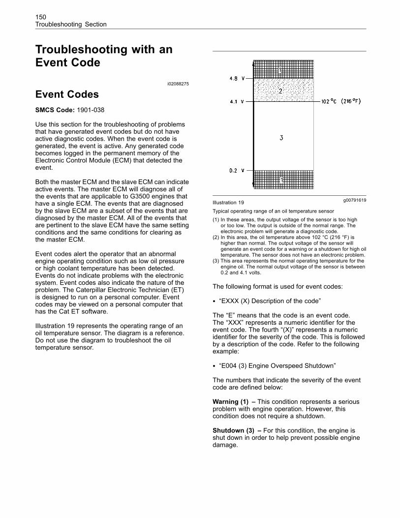
150Troubleshooting Section
Troubleshooting with anEvent Code
i02088275
Event CodesSMCS Code: 1901-038
Use this section for the troubleshooting of problemsthat have generated event codes but do not haveactive diagnostic codes. When the event code isgenerated, the event is active. Any generated codebecomes logged in the permanent memory of theElectronic Control Module (ECM) that detected theevent.
Both the master ECM and the slave ECM can indicateactive events. The master ECM will diagnose all ofthe events that are applicable to G3500 engines thathave a single ECM. The events that are diagnosedby the slave ECM are a subset of the events that arediagnosed by the master ECM. All of the events thatare pertinent to the slave ECM have the same settingconditions and the same conditions for clearing asthe master ECM.
Event codes alert the operator that an abnormalengine operating condition such as low oil pressureor high coolant temperature has been detected.Events do not indicate problems with the electronicsystem. Event codes also indicate the nature of theproblem. The Caterpillar Electronic Technician (ET)is designed to run on a personal computer. Eventcodes may be viewed on a personal computer thathas the Cat ET software.
Illustration 19 represents the operating range of anoil temperature sensor. The diagram is a reference.Do not use the diagram to troubleshoot the oiltemperature sensor.
g00791619Illustration 19
Typical operating range of an oil temperature sensor(1) In these areas, the output voltage of the sensor is too high
or too low. The output is outside of the normal range. Theelectronic problem will generate a diagnostic code.
(2) In this area, the oil temperature above 102 °C (216 °F) ishigher than normal. The output voltage of the sensor willgenerate an event code for a warning or a shutdown for high oiltemperature. The sensor does not have an electronic problem.
(3) This area represents the normal operating temperature for theengine oil. The normal output voltage of the sensor is between0.2 and 4.1 volts.
The following format is used for event codes:
• “EXXX (X) Description of the code”
The “E” means that the code is an event code.The “XXX” represents a numeric identifier for theevent code. The fourth “(X)” represents a numericidentifier for the severity of the code. This is followedby a description of the code. Refer to the followingexample:
• “E004 (3) Engine Overspeed Shutdown”
The numbers that indicate the severity of the eventcode are defined below:
Warning (1) – This condition represents a seriousproblem with engine operation. However, thiscondition does not require a shutdown.
Shutdown (3) – For this condition, the engine isshut down in order to help prevent possible enginedamage.
151Troubleshooting Section
These responses to certain events may beprogrammed into the ECM. If the responses areprogrammed, Cat ET can display the event. If theresponses are not programmed, the display will notappear. However, the occurrence of any event willcause the event code to be logged in the ECM thatdetected the event.
Note: Do not confuse event codes with diagnosticcodes. For information on diagnostic codes, seeTroubleshooting, “Troubleshooting with a DiagnosticCode”.
Perform the following tasks before you troubleshootthe event code:
• Gather enough information about the complaint inorder to describe the symptom(s) adequately.
• Verify that the complaint is not due to normalengine operation.
• Repair all active diagnostic codes. SeeTroubleshooting, “Troubleshooting With ADiagnostic Code”.
TroubleshootingFor basic troubleshooting of the engine, performthe following steps first in order to diagnose amalfunction.
1. Gather information about the complaint from theoperator.
2. Verify that the complaint is not due to normalengine operation. Verify that the complaint is notdue to error of the operator.
3. Perform a visual inspection. Inspect the followingitems:
• Fuel supply
• Oil level
• Oil supply
• Wiring
• Connectors
4. Check the diagnostic codes and event codes.Repair any active codes.
If these inspections do not reveal any problems,identify the probable causes with the procedures inthis manual that best describe the symptoms. Checkeach probable cause according to the tests that arerecommended.
Be sure to check the connectors. This is speciallytrue for problems that are intermittent. SeeTroubleshooting, “Inspecting Electrical Connectors”.
Narrow the probable cause. Consider the operatorinformation, the conditions of operation, and thehistory of the engine.
Operator InformationObtain the following information from the operator:
• The occurrence and the time of the occurrence
• Determine the conditions for the occurrence. Theconditions will include the engine rpm and the load.
• Determine if there are any systems that wereinstalled by the dealer or the customer that couldcause the symptom.
• Determine whether any other occurrenceshappened in addition to the symptom.
Diagnostic Codes and Event CodesExamine the following information regarding anycodes:
• The probable cause of the symptom is correlatedto the code.
• The code was generated when the symptomoccurred.
• Codes that are repeatedly logged
• The complaint is not due to normal engineoperation.
Other SymptomsIf other occurrences happened in addition to thesymptom, investigate the following conditions:
• The other occurrences are related to the symptom.
• The symptoms have a probable cause that iscommon.
Active Event CodesAn active event code represents a problem withengine operation. Correct the problem as soon aspossible.
152Troubleshooting Section
Both the master ECM and the slave ECM canindicate active events. When an event code is active,the “Active Alarm” indicator (“Engine Control AlarmStatus” on Cat ET) is activated in order to alert theoperator. If the condition that generated the codeis momentary, the message disappears. The eventcode will be logged in the memory of the ECM thatdetected the event.
Active event codes are listed in ascending numericalorder on Cat ET. The code with the lowest numberis listed first.
Logged Event CodesThe master ECM and the slave ECM can log events.When an ECM generates an event code the ECMlogs the code in permanent memory. Each ECM hasan internal diagnostic clock. Each ECM will recordthe following information when a code is generated:
• The hour of the first occurrence of the code
• The hour of the last occurrence of the code
• The number of occurrences of the code
This information can be helpful for troubleshootingintermittent problems. Logged codes can also beused to review the performance of the engine.
A code is cleared from memory when one of thefollowing conditions occur:
• The service technician manually clears the code.
• The code does not recur for 1000 hours.
• A new code is logged and there are already tencodes in memory. In this case, the oldest code iscleared.
Logged events are listed in chronological order. Themost recent event code is listed first.
Note: Always clear logged event codes afterinvestigating and correcting the problem whichgenerated the code.
i01761523
E004 Engine OverspeedShutdownSMCS Code: 1348-038
Conditions Which Generate This Code:
The engine rpm has exceeded the trip point thatis programmed into the master Electronic ControlModule (ECM) and the delay time has expired. Themaster ECM has determined that the detected speedis accurate.
System Response:
The gas shutoff valve and the ignition are shut off.The shutdown output is activated. The code is logged.
Possible Performance Effect:
The engine is shut down.
Troubleshooting:
Refer to Troubleshooting, “Engine Overspeed”.
Results:
• OK – STOP.
i01633543
E016 High Engine CoolantTemperature ShutdownSMCS Code: 1395-038
Conditions Which Generate This Code:
The crank terminate relay is set and the engine hasbeen running for at least 30 seconds. The enginecoolant temperature has exceeded the trip point andthe delay time has expired. No other codes for theengine coolant are active.
System Response:
The fuel is shut off. The shutdown output is activated.The code is logged.
Possible Performance Effect:
The engine is shut down.
Troubleshooting:
Refer to Troubleshooting, “Engine CoolantTemperature (High)”.
153Troubleshooting Section
Results:
• OK – STOP.
i01633545
E017 High Engine CoolantTemperature WarningSMCS Code: 1395-038
Conditions Which Generate This Code:
The crank terminate relay is set and the engine hasbeen running for at least 30 seconds. The enginecoolant temperature has exceeded the trip point andthe delay time has expired. No other codes for theengine coolant are active.
System Response:
The alarm output is activated. The code is logged.
Possible Performance Effect:
The engine operation is not immediately affected.However, if the coolant temperature continues to rise,the engine will be shut down.
Troubleshooting:
Refer to Troubleshooting, “Engine CoolantTemperature (High)”.
Results:
• OK – STOP.
i01633603
E019 High Engine OilTemperature ShutdownSMCS Code: 1348-038
Conditions Which Generate This Code:
The crank terminate relay is set and the engine hasbeen running for at least 30 seconds. The engineoil temperature has exceeded the trip point and thedelay time has expired. No other codes for the engineoil temperature are active.
System Response:
The fuel is shut off. The shutdown output is activated.The code is logged.
Possible Performance Effect:
The engine is shut off.
Troubleshooting:
Refer to Troubleshooting, “Engine Oil Temperature(High)”.
Results:
• OK – STOP.
i01633605
E020 High Engine OilTemperature WarningSMCS Code: 1348-038
Conditions Which Generate This Code:
The crank terminate relay is set and the engine hasbeen running for at least 30 seconds. The engineoil temperature has exceeded the trip point and thedelay time has expired. No other codes for the engineoil temperature are active.
System Response:
The alarm output is activated. The code is logged.
Possible Performance Effect:
The engine operation is not immediately affected.However, if the engine oil temperature continues torise, the engine can be shut down.
Troubleshooting:
Refer to Troubleshooting, “Engine Oil Temperature(High)”.
Results:
• OK – STOP.
i01633755
E026 High Inlet AirTemperature ShutdownSMCS Code: 1050-038
Conditions Which Generate This Code:
The crank terminate relay is set and the engine hasbeen running for at least 30 seconds. The inlet airtemperature has exceeded the trip point and thedelay time has expired. No other codes for the inletair temperature are active.
154Troubleshooting Section
System Response:
The fuel is shut off. The shutdown output is activated.The code is logged.
Possible Performance Effect:
The engine is shut down.
Troubleshooting:
Refer to Troubleshooting, “Inlet Air Temperature(High)”.
Results:
• OK – STOP.
i01633756
E027 High Inlet AirTemperature WarningSMCS Code: 1050-038
Conditions Which Generate This Code:
The crank terminate relay is set and the engine hasbeen running for at least 30 seconds. The inlet airtemperature has exceeded the trip point and thedelay time has expired. No other codes for the inletair temperature are active.
System Response:
The alarm output is activated. The code is logged.
Possible Performance Effect:
The engine operation is not immediately affected.However, if the inlet air temperature continues to rise,the engine may be shut down.
Troubleshooting:
Refer to Troubleshooting, “Inlet Air Temperature(High)”.
Results:
• OK – STOP.
i01633757
E038 Low Engine CoolantTemperature WarningSMCS Code: 1395-038
Conditions Which Generate This Code:
The crank terminate relay is set and the enginehas been running for at least 30 seconds. Thetemperature of the engine coolant is less than the trippoint and the delay time has expired. No other codesfor the coolant temperature are active.
System Response:
The alarm output is activated. The code is logged.
Possible Performance Effect:
The engine operation is not immediately affected.
Troubleshooting:
Refer to Troubleshooting, “Engine CoolantTemperature (Low)”.
Results:
• OK – STOP.
i01633762
E040 Low Engine Oil PressureShutdownSMCS Code: 1348-038-PX
Conditions Which Generate This Code:
The crank terminate relay is set and the engine hasbeen running for at least 10 seconds. The engine oilpressure is less than the trip point and the delay timehas expired. No codes for the engine oil pressuresensor are active.
System Response:
The fuel is shut off. The shutdown output is activated.The code is logged.
Possible Performance Effect:
The engine is shut down.
Troubleshooting:
Refer to Troubleshooting, “Engine Oil Pressure(Low)”.
155Troubleshooting Section
Results:
• OK – STOP.
i01633763
E042 Low System VoltageShutdownSMCS Code: 1400-038
Conditions Which Generate This Code:
The voltage is less than the trip point and the delaytime has expired. No other codes for the systemvoltage are present.
System Response:
The shutdown output is activated. The code is logged.
Possible Performance Effect:
The engine is shut down.
Troubleshooting:
Refer to Troubleshooting, “System Voltage”.
Results:
• OK – STOP.
i01633765
E043 Low System VoltageWarningSMCS Code: 1400-038
Conditions Which Generate This Code:
The voltage is less than the trip point and the delaytime has expired. No other codes for the systemvoltage are present.
System Response:
The alarm output is activated. The code is logged.
Possible Performance Effect:
The engine operation is not immediately affected.However, if the system voltage continues to bereduced, the engine will be shut down.
Troubleshooting:
Refer to Troubleshooting, “System Voltage”.
Results:
• OK – STOP.
i01877738
E050 High System VoltageWarningSMCS Code: 1400-038
Conditions Which Generate This Code:
The voltage is greater than the trip point and thedelay time has expired. No other codes for thesystem voltage are present.
System Response:
The alarm output is activated. The code is logged.
Possible Performance Effect:
The engine operation is not immediately affected.However, engine components could be damaged ifthe system voltage continues to increase.
Troubleshooting:
Refer to Troubleshooting, “System Voltage”.
Results:
• OK – STOP.
i01637578
E053 Low Fuel PressureWarningSMCS Code: 1250-038
Conditions Which Generate This Code:
The fuel pressure is less than the trip point and thedelay time has expired.
System Response:
The alarm output is activated. The code is logged.
Possible Performance Effect:
The engine operation is not immediately affected.However, if the fuel pressure continues to bereduced, the supply may become inadequate for thefuel metering valve.
Troubleshooting:
Refer to Troubleshooting, “Fuel Pressure”.
156Troubleshooting Section
Results:
• OK – STOP.
i01637590
E096 High Fuel PressureSMCS Code: 1250-038
Conditions Which Generate This Code:
The fuel pressure is higher than the trip point and thedelay time has expired.
System Response:
The alarm output is activated. The code is logged.
Possible Performance Effect:
The engine operation is not immediately affected.However, if the fuel pressure continues to increase,the supply may exceed the maximum limit for the fuelmetering valve.
Troubleshooting:
Refer to Troubleshooting, “Fuel Pressure”.
Results:
• OK – STOP.
i01633787
E100 Low Engine Oil PressureWarningSMCS Code: 1348-038
Conditions Which Generate This Code:
The crank terminate relay is set and the engine hasbeen running for at least ten seconds. The engineoil pressure is less than the trip point and the delaytime has expired. There are no active codes for theengine oil pressure sensor.
System Response:
The alarm output is activated. The code is logged.
Possible Performance Effect:
The engine operation is not immediately affected.However, if the oil pressure continues to be reduced,the engine may be shut down.
Troubleshooting:
Refer to Troubleshooting, “Engine Oil Pressure(Low)”.
Results:
• OK – STOP.
i01633790
E127 Engine Oil Filter DiffPressure Low WarningSMCS Code: 1308-038
Conditions Which Generate This Code:
The crank terminate relay is set and the engine hasbeen running for at least 30 seconds. The engine oilfilter differential pressure is less than the trip pointand the delay time has expired. There are no activecodes for the oil pressure sensors.
System Response:
The alarm output is activated. The code is logged.
Possible Performance Effect:
The engine operation is not immediately affected.However, if the engine oil filter differential pressurecontinues to be reduced, the engine may be shutdown.
Troubleshooting:
Refer to Troubleshooting, “Engine Oil FilterDifferential Pressure”.
Results:
• OK – STOP.
i01633814
E128 Engine Oil Filter DiffPressure Low ShutdownSMCS Code: 1308-038
Conditions Which Generate This Code:
The crank terminate relay is set and the engine hasbeen running for at least 30 seconds. The oil filterdifferential pressure is less than the trip point and thedelay time has expired. There are no active codes forthe oil pressure sensors.
157Troubleshooting Section
System Response:
The fuel is shut off. The shutdown output is activated.The code is logged.
Possible Performance Effect:
The engine is shut down.
Troubleshooting:
Refer to Troubleshooting, “Engine Oil FilterDifferential Pressure”.
Results:
• OK – STOP.
i01633828
E129 Engine Oil Filter DiffPressure High WarningSMCS Code: 1308-038
Conditions Which Generate This Code:
The crank terminate relay is set and the engine hasbeen running for at least 30 seconds. The oil filterdifferential pressure is greater than the trip pointand the delay time has expired. There are no activecodes for the oil pressure sensors.
System Response:
The alarm output is activated. The code is logged.
Possible Performance Effect:
The engine operation is not immediately affected.However, if the oil filter differential pressure continuesto increase, the engine may be shut down.
Troubleshooting:
Refer to Troubleshooting, “Engine Oil FilterDifferential Pressure”.
Results:
• OK – STOP.
i01633832
E130 Engine Oil Filter DiffPressure High ShutdownSMCS Code: 1308-038
Conditions Which Generate This Code:
The crank terminate relay is set and the engine hasbeen running for at least 30 seconds. The engine oilfilter differential pressure is greater than the trip pointand the delay time has expired. There are no activecodes for the oil pressure sensors.
System Response:
The fuel is shut off. The shutdown output is activated.The code is logged.
Possible Performance Effect:
The engine is shut down.
Troubleshooting:
Refer to Troubleshooting, “Engine Oil FilterDifferential Pressure”.
Results:
• OK – STOP.
i01633833
E135 Low Jacket WaterPressure ShutdownSMCS Code: 1350-038
Conditions Which Generate This Code:
The crank terminate relay is set and the engine hasbeen running for at least ten seconds. The pressureof the jacket water is less than the trip point and thedelay time has expired. There are no active codes forthe pressure sensor at the outlet for the jacket water.
System Response:
The fuel is shut off. The shutdown output is activated.The code is logged.
Possible Performance Effect:
The engine is shut off.
Troubleshooting:
Refer to Troubleshooting, “Jacket Water Pressure(Low)”.
158Troubleshooting Section
Results:
• OK – STOP.
i01633954
E223 High Gas TemperatureSMCS Code: 1250-038
Conditions Which Generate This Code:
The crank terminate relay is set and the enginehas been running for at least 30 seconds. Thetemperature of the gas has exceeded the trip pointand the delay timer has expired. There are no activecodes for the fuel temperature sensor.
System Response:
The alarm output is activated. The code is logged.
Possible Performance Effect:
The engine operation is not immediately affected.However, if the fuel temperature continues toincrease, the air/fuel ratio and the inlet manifold airtemperature can be affected.
Troubleshooting:
Refer to Troubleshooting, “Gas Temperature (High)”.
Results:
• OK – STOP.
i01633956
E224 High Jacket Water InletPressureSMCS Code: 1350-038
Conditions Which Generate This Code:
The crank terminate relay is set and the engine hasbeen running for at least 10 seconds. The trip pointfor high pressure at the inlet for the jacket water hasbeen exceeded and the delay time has expired.
System Response:
The fuel is shut off. The shutdown output is activated.The code is logged.
Possible Performance Effect:
The engine is shut down.
Troubleshooting:
Refer to Troubleshooting, “Jacket Water InletPressure (High)”.
Results:
• OK – STOP.
i01633959
E225 Engine OvercrankSMCS Code: 1400-038
Conditions Which Generate This Code:
The engine did not start within the programmedparameters for starting.
System Response:
The fuel is shut off. Engine cranking is prevented.The code is logged.
Possible Performance Effect:
The engine will not start.
Troubleshooting:
Refer to Troubleshooting, “Engine Overcrank”.
Results:
• OK – STOP.
i01761561
E226 Driven Equipment NotReadySMCS Code: 1404-038
Conditions Which Generate This Code:
The engine is ready to start. However, the masterElectronic Control Module (ECM) has received asignal which indicates that the driven equipment isnot ready for the engine to start.
System Response:
The shutdown output is activated. Engine crankingis prevented. The code is logged.
Possible Performance Effect:
The engine will not start.
159Troubleshooting Section
Troubleshooting:
Refer to Troubleshooting, “Driven Equipment”.
Results:
• OK – STOP.
i01633972
E229 Fuel Energy ContentSetting LowSMCS Code: 1250-038
Conditions Which Generate This Code:
The crank terminate relay is set and the enginehas been running for at least 30 seconds. The fuelcorrection factor is less than the trip point for 20seconds.
System Response:
The alarm output is activated. The code is logged.
Possible Performance Effect:
The engine performance may be erratic.
Troubleshooting:
Refer to Troubleshooting, “Fuel Energy Content”.
Results:
• OK – STOP.
i01633976
E230 Fuel Energy ContentSetting HighSMCS Code: 1250-038
Conditions Which Generate This Code:
The crank terminate relay is set and the enginehas been running for at least 30 seconds. The fuelcorrection factor is greater than the trip point for 20seconds.
System Response:
The alarm output is activated. The code is logged.
Possible Performance Effect:
The engine performance may be erratic.
Troubleshooting:
Refer to Troubleshooting, “Fuel Energy Content”.
Results:
• OK – STOP.
i01746483
E231 Fuel Quality Out of RangeSMCS Code: 1250-038
Conditions Which Generate This Code:
The crank terminate relay is set and the engine hasbeen running for at least 30 seconds. The Low HeatValue (LHV) of the fuel is less than the trip point ORthe LHV of the fuel is greater than the trip point for20 seconds.
System Response:
The fuel is shut off. The shutdown output is activated.The code is logged.
Possible Performance Effect:
The engine is shut off.
Troubleshooting:
Refer to Troubleshooting, “Fuel Energy Content”.
Results:
• OK – STOP.
i01634015
E243 High Left Turbo TurbineOutlet TemperatureSMCS Code: 1052-038
Conditions Which Generate This Code:
The temperature at the outlet for the left turbochargerturbine has exceeded the trip point and the delaytime has expired.
System Response:
The following event codes are logged according tothe trip points for the temperature:
• E243 (1) High Left Turbo Turbine OutletTemperature (warning)
• E243 (3) High Left Turbo Turbine OutletTemperature (shutdown)
160Troubleshooting Section
If a warning is generated, the alarm output isactivated.
If a shutdown is generated, the shutdown output isactivated.
Possible Performance Effect:
If a warning is generated, the engine performance isnot immediately affected.
The engine will be shut down if the trip point for theshutdown is exceeded.
Troubleshooting:
Refer to Troubleshooting, “Turbocharger TurbineTemperature (High)”.
Results:
• OK – STOP.
i01634039
E244 High Right Turbo TurbineOutlet TemperatureSMCS Code: 1052-038
Conditions Which Generate This Code:
The temperature at the outlet for the rightturbocharger turbine has exceeded the trip point andthe delay time has expired.
System Response:
The following event codes are logged according tothe trip points for the temperature:
• E244 (1) High Right Turbo Turbine OutletTemperature (warning)
• E244 (3) High Right Turbo Turbine OutletTemperature (shutdown)
If a warning is generated, the alarm output isactivated.
If a shutdown is generated, the shutdown output isactivated.
Possible Performance Effect:
If a warning is generated, the engine performance isnot immediately affected.
The engine will be shut down if the trip point for theshutdown is exceeded.
Troubleshooting:
Refer to Troubleshooting, “Turbocharger TurbineTemperature (High)”.
Results:
• OK – STOP.
i01634041
E245 High Right Turbo TurbineInlet TemperatureSMCS Code: 1052-038
Conditions Which Generate This Code:
The temperature at the inlet for the right turbochargerturbine has exceeded the trip point and the delaytime has expired.
System Response:
The following event codes are logged according tothe trip points for the temperature:
• E245 (1) High Right Turbo Turbine InletTemperature (warning)
• E245 (3) High Right Turbo Turbine InletTemperature (shutdown)
If a warning is generated, the alarm output isactivated.
If a shutdown is generated, the shutdown output isactivated.
Possible Performance Effect:
If a warning is generated, the engine performance isnot immediately affected.
The engine will be shut down if the trip point for theshutdown is exceeded.
Troubleshooting:
Refer to Troubleshooting, “Turbocharger TurbineTemperature (High)”.
Results:
• OK – STOP.
161Troubleshooting Section
i01634043
E246 High Left Turbo TurbineInlet TemperatureSMCS Code: 1052-038
Conditions Which Generate This Code:
The temperature at the inlet for the left turbochargerturbine has exceeded the trip point and the delaytime has expired.
System Response:
The following event codes are logged according tothe trip points for the temperature:
• E246 (1) High Left Turbo Turbine Inlet Temperature(warning)
• E246 (3) High Left Turbo Turbine Inlet Temperature(shutdown)
If a warning is generated, the alarm output isactivated.
If a shutdown is generated, the shutdown output isactivated.
Possible Performance Effect:
If a warning is generated, the engine performance isnot immediately affected.
The engine will be shut down if the trip point for theshutdown is exceeded.
Troubleshooting:
Refer to Troubleshooting, “Turbocharger TurbineTemperature (High)”.
Results:
• OK – STOP.
i01634059
E264 Emergency StopActivatedSMCS Code: 1400-038
Conditions Which Generate This Code:
The input for the emergency stop is activated.
System Response:
The gas shutoff valve (GSOV) and the ignition areshut off. The shutdown output is activated. The codeis logged.
Possible Performance Effect:
The engine is shut off.
Troubleshooting:
Refer to Troubleshooting, “Engine Shutdown”.
Results:
• OK – STOP.
i01634063
E268 Unexpected EngineShutdownSMCS Code: 1400-038
Conditions Which Generate This Code:
The crank terminate relay is set and the engine isrunning. The engine rpm is less than the programmedspeed of the postlube cycle for 200 ms.
System Response:
The fuel is shut off. The shutdown output is activated.The code is logged.
Possible Performance Effect:
The engine is shut down.
Troubleshooting:
Refer to Troubleshooting, “Engine Shutdown(Unexpected)”.
Results:
• OK – STOP.
i01634093
E269 Customer ShutdownRequestedSMCS Code: 1400-038
Conditions Which Generate This Code:
The engine is either cranking or running. The inputfor the stop is set for 200 ms.
162Troubleshooting Section
System Response:
The fuel is shut off. The shutdown output is activated.The code is logged.
Possible Performance Effect:
The engine is shut off.
Troubleshooting:
Refer to Troubleshooting, “Engine Shutdown”.
Results:
• OK – STOP.
i01634097
E270 Driven EquipmentShutdown RequestedSMCS Code: 1400-038
Conditions Which Generate This Code:
The crank terminate relay is set and the engine isrunning. The input requests a shutdown for 200 ms.
System Response:
The fuel is shut off. The shutdown output is activated.The code is logged.
Possible Performance Effect:
The engine is shut down.
Troubleshooting:
Refer to Troubleshooting, “Driven Equipment”.
Results:
• OK – STOP.
i01864896
E337 High Engine Oil to EngineCoolant Diff TempSMCS Code: 1350-038
Conditions Which Generate This Code:
The crank terminate relay is set and the engine hasbeen running for at least 30 seconds. The differentialbetween the temperature of the engine oil and thetemperature of the engine coolant has exceeded thetrip point. Also, the delay time has expired. There areno active codes for the sensors for the engine oiltemperature and the engine coolant.
System Response:
The following event codes are logged according tothe trip points for the temperature differential:
• E337 (1) High Engine Oil to Engine Coolant DiffTemp (warning)
• E337 (3) High Engine Oil to Engine Coolant DiffTemp (shutdown)
If a warning is activated, the alarm output is activated.
If a shutdown is activated, the shutdown output isactivated.
Possible Performance Effect:
If a warning is generated, the engine operation is notimmediately affected.
The engine will be shut down if the trip point for theshutdown is exceeded.
Troubleshooting:
Refer to Troubleshooting, “Jacket Water to EngineOil Differential Temperature (Low)”.
Results:
• OK – STOP.
163Troubleshooting Section
i01637607
E401 Cylinder #1 DetonationSMCS Code: 1000-038
Conditions Which Generate This Code:
The level of detonation has exceeded the trip point.There is no active diagnostic code for the cylinder’sdetonation sensor.
System Response:
The alarm output is activated. The code is logged.
Possible Performance Effect:
The engine performance may be affected by anadjustment of the timing in order to reduce detonation.
Troubleshooting:
Refer to Troubleshooting, “Detonation”.
Results:
• OK – STOP.
i01637623
E402 Cylinder #2 DetonationSMCS Code: 1000-038
Conditions Which Generate This Code:
The level of detonation has exceeded the trip point.There is no active diagnostic code for the cylinder’sdetonation sensor.
System Response:
The alarm output is activated. The code is logged.
Possible Performance Effect:
The engine performance may be affected by anadjustment of the timing in order to reduce detonation.
Troubleshooting:
Refer to Troubleshooting, “Detonation”.
Results:
• OK – STOP.
i01637627
E403 Cylinder #3 DetonationSMCS Code: 1000-038
Conditions Which Generate This Code:
The level of detonation has exceeded the trip point.There is no active diagnostic code for the cylinder’sdetonation sensor.
System Response:
The alarm output is activated. The code is logged.
Possible Performance Effect:
The engine performance may be affected by anadjustment of the timing in order to reduce detonation.
Troubleshooting:
Refer to Troubleshooting, “Detonation”.
Results:
• OK – STOP.
i01637634
E404 Cylinder #4 DetonationSMCS Code: 1000-038
Conditions Which Generate This Code:
The level of detonation has exceeded the trip point.There is no active diagnostic code for the cylinder’sdetonation sensor.
System Response:
The alarm output is activated. The code is logged.
Possible Performance Effect:
The engine performance may be affected by anadjustment of the timing in order to reduce detonation.
Troubleshooting:
Refer to Troubleshooting, “Detonation”.
Results:
• OK – STOP.
164Troubleshooting Section
i01637642
E405 Cylinder #5 DetonationSMCS Code: 1000-038
Conditions Which Generate This Code:
The level of detonation has exceeded the trip point.There is no active diagnostic code for the cylinder’sdetonation sensor.
System Response:
The alarm output is activated. The code is logged.
Possible Performance Effect:
The engine performance may be affected by anadjustment of the timing in order to reduce detonation.
Troubleshooting:
Refer to Troubleshooting, “Detonation”.
Results:
• OK – STOP.
i01637646
E406 Cylinder #6 DetonationSMCS Code: 1000-038
Conditions Which Generate This Code:
The level of detonation has exceeded the trip point.There is no active diagnostic code for the cylinder’sdetonation sensor.
System Response:
The alarm output is activated. The code is logged.
Possible Performance Effect:
The engine performance may be affected by anadjustment of the timing in order to reduce detonation.
Troubleshooting:
Refer to Troubleshooting, “Detonation”.
Results:
• OK – STOP.
i01637648
E407 Cylinder #7 DetonationSMCS Code: 1000-038
Conditions Which Generate This Code:
The level of detonation has exceeded the trip point.There is no active diagnostic code for the cylinder’sdetonation sensor.
System Response:
The alarm output is activated. The code is logged.
Possible Performance Effect:
The engine performance may be affected by anadjustment of the timing in order to reduce detonation.
Troubleshooting:
Refer to Troubleshooting, “Detonation”.
Results:
• OK – STOP.
i01637651
E408 Cylinder #8 DetonationSMCS Code: 1000-038
Conditions Which Generate This Code:
The level of detonation has exceeded the trip point.There is no active diagnostic code for the cylinder’sdetonation sensor.
System Response:
The alarm output is activated. The code is logged.
Possible Performance Effect:
The engine performance may be affected by anadjustment of the timing in order to reduce detonation.
Troubleshooting:
Refer to Troubleshooting, “Detonation”.
Results:
• OK – STOP.
165Troubleshooting Section
i01637653
E409 Cylinder #9 DetonationSMCS Code: 1000-038
Conditions Which Generate This Code:
The level of detonation has exceeded the trip point.There is no active diagnostic code for the cylinder’sdetonation sensor.
System Response:
The alarm output is activated. The code is logged.
Possible Performance Effect:
The engine performance may be affected by anadjustment of the timing in order to reduce detonation.
Troubleshooting:
Refer to Troubleshooting, “Detonation”.
Results:
• OK – STOP.
i01637657
E410 Cylinder #10 DetonationSMCS Code: 1000-038
Conditions Which Generate This Code:
The level of detonation has exceeded the trip point.There is no active diagnostic code for the cylinder’sdetonation sensor.
System Response:
The alarm output is activated. The code is logged.
Possible Performance Effect:
The engine performance may be affected by anadjustment of the timing in order to reduce detonation.
Troubleshooting:
Refer to Troubleshooting, “Detonation”.
Results:
• OK – STOP.
i01637663
E411 Cylinder #11 DetonationSMCS Code: 1000-038
Conditions Which Generate This Code:
The level of detonation has exceeded the trip point.There is no active diagnostic code for the cylinder’sdetonation sensor.
System Response:
The alarm output is activated. The code is logged.
Possible Performance Effect:
The engine performance may be affected by anadjustment of the timing in order to reduce detonation.
Troubleshooting:
Refer to Troubleshooting, “Detonation”.
Results:
• OK – STOP.
i01637665
E412 Cylinder #12 DetonationSMCS Code: 1000-038
Conditions Which Generate This Code:
The level of detonation has exceeded the trip point.There is no active diagnostic code for the cylinder’sdetonation sensor.
System Response:
The alarm output is activated. The code is logged.
Possible Performance Effect:
The engine performance may be affected by anadjustment of the timing in order to reduce detonation.
Troubleshooting:
Refer to Troubleshooting, “Detonation”.
Results:
• OK – STOP.

166Troubleshooting Section
i01637696
E413 Cylinder #13 DetonationSMCS Code: 1000-038
Conditions Which Generate This Code:
The level of detonation has exceeded the trip point.There is no active diagnostic code for the cylinder’sdetonation sensor.
System Response:
The alarm output is activated. The code is logged.
Possible Performance Effect:
The engine performance may be affected by anadjustment of the timing in order to reduce detonation.
Troubleshooting:
Refer to Troubleshooting, “Detonation”.
Results:
• OK – STOP.
i01637699
E414 Cylinder #14 DetonationSMCS Code: 1000-038
Conditions Which Generate This Code:
The level of detonation has exceeded the trip point.There is no active diagnostic code for the cylinder’sdetonation sensor.
System Response:
The alarm output is activated. The code is logged.
Possible Performance Effect:
The engine performance may be affected by anadjustment of the timing in order to reduce detonation.
Troubleshooting:
Refer to Troubleshooting, “Detonation”.
Results:
• OK – STOP.
i01637702
E415 Cylinder #15 DetonationSMCS Code: 1000-038
Conditions Which Generate This Code:
The level of detonation has exceeded the trip point.There is no active diagnostic code for the cylinder’sdetonation sensor.
System Response:
The alarm output is activated. The code is logged.
Possible Performance Effect:
The engine performance may be affected by anadjustment of the timing in order to reduce detonation.
Troubleshooting:
Refer to Troubleshooting, “Detonation”.
Results:
• OK – STOP.
i01637706
E416 Cylinder #16 DetonationSMCS Code: 1000-038
Conditions Which Generate This Code:
The level of detonation has exceeded the trip point.There is no active diagnostic code for the cylinder’sdetonation sensor.
System Response:
The alarm output is activated. The code is logged.
Possible Performance Effect:
The engine performance may be affected by anadjustment of the timing in order to reduce detonation.
Troubleshooting:
Refer to Troubleshooting, “Detonation”.
Results:
• OK – STOP.

167Troubleshooting Section
i01762523
E417 Cylinder #17 DetonationSMCS Code: 1000-038
Conditions Which Generate This Code:
The level of detonation has exceeded the trip point.There is no active diagnostic code for the cylinder’sdetonation sensor.
System Response:
The alarm output is activated. The code is logged.
Possible Performance Effect:
The engine performance may be affected by anadjustment of the timing in order to reduce detonation.
Troubleshooting:
Refer to Troubleshooting, “Detonation”.
Results:
• OK – STOP.
i01762524
E418 Cylinder #18 DetonationSMCS Code: 1000-038
Conditions Which Generate This Code:
The level of detonation has exceeded the trip point.There is no active diagnostic code for the cylinder’sdetonation sensor.
System Response:
The alarm output is activated. The code is logged.
Possible Performance Effect:
The engine performance may be affected by anadjustment of the timing in order to reduce detonation.
Troubleshooting:
Refer to Troubleshooting, “Detonation”.
Results:
• OK – STOP.
i01762525
E419 Cylinder #19 DetonationSMCS Code: 1000-038
Conditions Which Generate This Code:
The level of detonation has exceeded the trip point.There is no active diagnostic code for the cylinder’sdetonation sensor.
System Response:
The alarm output is activated. The code is logged.
Possible Performance Effect:
The engine performance may be affected by anadjustment of the timing in order to reduce detonation.
Troubleshooting:
Refer to Troubleshooting, “Detonation”.
Results:
• OK – STOP.
i01762527
E420 Cylinder #20 DetonationSMCS Code: 1000-038
Conditions Which Generate This Code:
The level of detonation has exceeded the trip point.There is no active diagnostic code for the cylinder’sdetonation sensor.
System Response:
The alarm output is activated. The code is logged.
Possible Performance Effect:
The engine performance may be affected by anadjustment of the timing in order to reduce detonation.
Troubleshooting:
Refer to Troubleshooting, “Detonation”.
Results:
• OK – STOP.
168Troubleshooting Section
i01634664
E421 Cylinder #1 DetonationShutdownSMCS Code: 1000-038
Conditions Which Generate This Code:
The level of detonation has exceeded the trip point.Maximum retardation of the timing was unable tocontrol the detonation adequately during the numberof ignition sparks that are allowed. There is no activediagnostic code for the cylinder’s detonation sensor.
System Response:
The fuel is shut off. The shutdown output is activated.The code is logged.
Possible Performance Effect:
The engine is shut down.
Troubleshooting:
Refer to Troubleshooting, “Detonation”.
Results:
• OK – STOP.
i01634746
E422 Cylinder #2 DetonationShutdownSMCS Code: 1000-038
Conditions Which Generate This Code:
The level of detonation has exceeded the trip point.Maximum retardation of the timing was unable tocontrol the detonation adequately during the numberof ignition sparks that are allowed. There is no activediagnostic code for the cylinder’s detonation sensor.
System Response:
The fuel is shut off. The shutdown output is activated.The code is logged.
Possible Performance Effect:
The engine is shut down.
Troubleshooting:
Refer to Troubleshooting, “Detonation”.
Results:
• OK – STOP.
i01634838
E423 Cylinder #3 DetonationShutdownSMCS Code: 1000-038
Conditions Which Generate This Code:
The level of detonation has exceeded the trip point.Maximum retardation of the timing was unable tocontrol the detonation adequately during the numberof ignition sparks that are allowed. There is no activediagnostic code for the cylinder’s detonation sensor.
System Response:
The fuel is shut off. The shutdown output is activated.The code is logged.
Possible Performance Effect:
The engine is shut down.
Troubleshooting:
Refer to Troubleshooting, “Detonation”.
Results:
• OK – STOP.
i01635415
E424 Cylinder #4 DetonationShutdownSMCS Code: 1000-038
Conditions Which Generate This Code:
The level of detonation has exceeded the trip point.Maximum retardation of the timing was unable tocontrol the detonation adequately during the numberof ignition sparks that are allowed. There is no activediagnostic code for the cylinder’s detonation sensor.
System Response:
The fuel is shut off. The shutdown output is activated.The code is logged.
Possible Performance Effect:
The engine is shut down.
169Troubleshooting Section
Troubleshooting:
Refer to Troubleshooting, “Detonation”.
Results:
• OK – STOP.
i01635416
E425 Cylinder #5 DetonationShutdownSMCS Code: 1000-038
Conditions Which Generate This Code:
The level of detonation has exceeded the trip point.Maximum retardation of the timing was unable tocontrol the detonation adequately during the numberof ignition sparks that are allowed. There is no activediagnostic code for the cylinder’s detonation sensor.
System Response:
The fuel is shut off. The shutdown output is activated.The code is logged.
Possible Performance Effect:
The engine is shut down.
Troubleshooting:
Refer to Troubleshooting, “Detonation”.
Results:
• OK – STOP.
i01635417
E426 Cylinder #6 DetonationShutdownSMCS Code: 1000-038
Conditions Which Generate This Code:
The level of detonation has exceeded the trip point.Maximum retardation of the timing was unable tocontrol the detonation adequately during the numberof ignition sparks that are allowed. There is no activediagnostic code for the cylinder’s detonation sensor.
System Response:
The fuel is shut off. The shutdown output is activated.The code is logged.
Possible Performance Effect:
The engine is shut down.
Troubleshooting:
Refer to Troubleshooting, “Detonation”.
Results:
• OK – STOP.
i01635420
E427 Cylinder #7 DetonationShutdownSMCS Code: 1000-038
Conditions Which Generate This Code:
The level of detonation has exceeded the trip point.Maximum retardation of the timing was unable tocontrol the detonation adequately during the numberof ignition sparks that are allowed. There is no activediagnostic code for the cylinder’s detonation sensor.
System Response:
The fuel is shut off. The shutdown output is activated.The code is logged.
Possible Performance Effect:
The engine is shut down.
Troubleshooting:
Refer to Troubleshooting, “Detonation”.
Results:
• OK – STOP.
i01635421
E428 Cylinder #8 DetonationShutdownSMCS Code: 1000-038
Conditions Which Generate This Code:
The level of detonation has exceeded the trip point.Maximum retardation of the timing was unable tocontrol the detonation adequately during the numberof ignition sparks that are allowed. There is no activediagnostic code for the cylinder’s detonation sensor.
170Troubleshooting Section
System Response:
The fuel is shut off. The shutdown output is activated.The code is logged.
Possible Performance Effect:
The engine is shut down.
Troubleshooting:
Refer to Troubleshooting, “Detonation”.
Results:
• OK – STOP.
i01635423
E429 Cylinder #9 DetonationShutdownSMCS Code: 1000-038
Conditions Which Generate This Code:
The level of detonation has exceeded the trip point.Maximum retardation of the timing was unable tocontrol the detonation adequately during the numberof ignition sparks that are allowed. There is no activediagnostic code for the cylinder’s detonation sensor.
System Response:
The fuel is shut off. The shutdown output is activated.The code is logged.
Possible Performance Effect:
The engine is shut down.
Troubleshooting:
Refer to Troubleshooting, “Detonation”.
Results:
• OK – STOP.
i01635424
E430 Cylinder #10 DetonationShutdownSMCS Code: 1000-038
Conditions Which Generate This Code:
The level of detonation has exceeded the trip point.Maximum retardation of the timing was unable tocontrol the detonation adequately during the numberof ignition sparks that are allowed. There is no activediagnostic code for the cylinder’s detonation sensor.
System Response:
The fuel is shut off. The shutdown output is activated.The code is logged.
Possible Performance Effect:
The engine is shut down.
Troubleshooting:
Refer to Troubleshooting, “Detonation”.
Results:
• OK – STOP.
i01635428
E431 Cylinder #11 DetonationShutdownSMCS Code: 1000-038
Conditions Which Generate This Code:
The level of detonation has exceeded the trip point.Maximum retardation of the timing was unable tocontrol the detonation adequately during the numberof ignition sparks that are allowed. There is no activediagnostic code for the cylinder’s detonation sensor.
System Response:
The fuel is shut off. The shutdown output is activated.The code is logged.
Possible Performance Effect:
The engine is shut down.
Troubleshooting:
Refer to Troubleshooting, “Detonation”.
171Troubleshooting Section
Results:
• OK – STOP.
i01635429
E432 Cylinder #12 DetonationShutdownSMCS Code: 1000-038
Conditions Which Generate This Code:
The level of detonation has exceeded the trip point.Maximum retardation of the timing was unable tocontrol the detonation adequately during the numberof ignition sparks that are allowed. There is no activediagnostic code for the cylinder’s detonation sensor.
System Response:
The fuel is shut off. The shutdown output is activated.The code is logged.
Possible Performance Effect:
The engine is shut down.
Troubleshooting:
Refer to Troubleshooting, “Detonation”.
Results:
• OK – STOP.
i01635431
E433 Cylinder #13 DetonationShutdownSMCS Code: 1000-038
Conditions Which Generate This Code:
The level of detonation has exceeded the trip point.Maximum retardation of the timing was unable tocontrol the detonation adequately during the numberof ignition sparks that are allowed. There is no activediagnostic code for the cylinder’s detonation sensor.
System Response:
The fuel is shut off. The shutdown output is activated.The code is logged.
Possible Performance Effect:
The engine is shut down.
Troubleshooting:
Refer to Troubleshooting, “Detonation”.
Results:
• OK – STOP.
i01635433
E434 Cylinder #14 DetonationShutdownSMCS Code: 1000-038
Conditions Which Generate This Code:
The level of detonation has exceeded the trip point.Maximum retardation of the timing was unable tocontrol the detonation adequately during the numberof ignition sparks that are allowed. There is no activediagnostic code for the cylinder’s detonation sensor.
System Response:
The fuel is shut off. The shutdown output is activated.The code is logged.
Possible Performance Effect:
The engine is shut down.
Troubleshooting:
Refer to Troubleshooting, “Detonation”.
Results:
• OK – STOP.
i01635435
E435 Cylinder #15 DetonationShutdownSMCS Code: 1000-038
Conditions Which Generate This Code:
The level of detonation has exceeded the trip point.Maximum retardation of the timing was unable tocontrol the detonation adequately during the numberof ignition sparks that are allowed. There is no activediagnostic code for the cylinder’s detonation sensor.
System Response:
The fuel is shut off. The shutdown output is activated.The code is logged.
172Troubleshooting Section
Possible Performance Effect:
The engine is shut down.
Troubleshooting:
Refer to Troubleshooting, “Detonation”.
Results:
• OK – STOP.
i01635436
E436 Cylinder #16 DetonationShutdownSMCS Code: 1000-038
Conditions Which Generate This Code:
The level of detonation has exceeded the trip point.Maximum retardation of the timing was unable tocontrol the detonation adequately during the numberof ignition sparks that are allowed. There is no activediagnostic code for the cylinder’s detonation sensor.
System Response:
The fuel is shut off. The shutdown output is activated.The code is logged.
Possible Performance Effect:
The engine is shut down.
Troubleshooting:
Refer to Troubleshooting, “Detonation”.
Results:
• OK – STOP.
i01762528
E437 Cylinder #17 DetonationShutdownSMCS Code: 1000-038
Conditions Which Generate This Code:
The level of detonation has exceeded the trip point.Maximum retardation of the timing was unable tocontrol the detonation adequately during the numberof ignition sparks that are allowed. There is no activediagnostic code for the cylinder’s detonation sensor.
System Response:
The fuel is shut off. The shutdown output is activated.The code is logged.
Possible Performance Effect:
The engine is shut down.
Troubleshooting:
Refer to Troubleshooting, “Detonation”.
Results:
• OK – STOP.
i01762529
E438 Cylinder #18 DetonationShutdownSMCS Code: 1000-038
Conditions Which Generate This Code:
The level of detonation has exceeded the trip point.Maximum retardation of the timing was unable tocontrol the detonation adequately during the numberof ignition sparks that are allowed. There is no activediagnostic code for the cylinder’s detonation sensor.
System Response:
The fuel is shut off. The shutdown output is activated.The code is logged.
Possible Performance Effect:
The engine is shut down.
Troubleshooting:
Refer to Troubleshooting, “Detonation”.
Results:
• OK – STOP.
173Troubleshooting Section
i01762530
E439 Cylinder #19 DetonationShutdownSMCS Code: 1000-038
Conditions Which Generate This Code:
The level of detonation has exceeded the trip point.Maximum retardation of the timing was unable tocontrol the detonation adequately during the numberof ignition sparks that are allowed. There is no activediagnostic code for the cylinder’s detonation sensor.
System Response:
The fuel is shut off. The shutdown output is activated.The code is logged.
Possible Performance Effect:
The engine is shut down.
Troubleshooting:
Refer to Troubleshooting, “Detonation”.
Results:
• OK – STOP.
i01762532
E440 Cylinder #20 DetonationShutdownSMCS Code: 1000-038
Conditions Which Generate This Code:
The level of detonation has exceeded the trip point.Maximum retardation of the timing was unable tocontrol the detonation adequately during the numberof ignition sparks that are allowed. There is no activediagnostic code for the cylinder’s detonation sensor.
System Response:
The fuel is shut off. The shutdown output is activated.The code is logged.
Possible Performance Effect:
The engine is shut down.
Troubleshooting:
Refer to Troubleshooting, “Detonation”.
Results:
• OK – STOP.
i01635494
E801 Cylinder #1 High ExhaustPort TempSMCS Code: 1059-038
Conditions Which Generate This Code:
The cylinder exhaust temperature has exceeded thetrip point and the delay time has expired.
System Response:
The following event codes are logged according tothe trip points for the temperature:
• E801 (1) Cylinder #1 High Exhaust Port Temp(warning)
• E801 (3) Cylinder #1 High Exhaust Port Temp(shutdown)
If a warning is generated, the alarm output isactivated.
If a shutdown is generated, the shutdown output isactivated and the fuel is shut off.
Possible Performance Effect:
If a warning is generated, the engine performance isnot immediately affected.
The engine will be shut down if the trip point for theshutdown is exceeded.
Troubleshooting:
Refer to Troubleshooting, “Exhaust Port Temperature(High)”.
Results:
• OK – STOP.
i01635500
E802 Cylinder #2 High ExhaustPort TempSMCS Code: 1059-038
Conditions Which Generate This Code:
The cylinder exhaust temperature has exceeded thetrip point and the delay time has expired.
174Troubleshooting Section
System Response:
The following event codes are logged according tothe trip points for the temperature:
• E802 (1) Cylinder #2 High Exhaust Port Temp(warning)
• E802 (3) Cylinder #2 High Exhaust Port Temp(shutdown)
If a warning is generated, the alarm output isactivated.
If a shutdown is generated, the shutdown output isactivated and the fuel is shut off.
Possible Performance Effect:
If a warning is generated, the engine performance isnot immediately affected.
The engine will be shut down if the trip point for theshutdown is exceeded.
Troubleshooting:
Refer to Troubleshooting, “Exhaust Port Temperature(High)”.
Results:
• OK – STOP.
i01635503
E803 Cylinder #3 High ExhaustPort TempSMCS Code: 1059-038
Conditions Which Generate This Code:
The cylinder exhaust temperature has exceeded thetrip point and the delay time has expired.
System Response:
The following event codes are logged according tothe trip points for the temperature:
• E803 (1) Cylinder #3 High Exhaust Port Temp(warning)
• E803 (3) Cylinder #3 High Exhaust Port Temp(shutdown)
If a warning is generated, the alarm output isactivated.
If a shutdown is generated, the shutdown output isactivated and the fuel is shut off.
Possible Performance Effect:
If a warning is generated, the engine performance isnot immediately affected.
The engine will be shut down if the trip point for theshutdown is exceeded.
Troubleshooting:
Refer to Troubleshooting, “Exhaust Port Temperature(High)”.
Results:
• OK – STOP.
i01635505
E804 Cylinder #4 High ExhaustPort TempSMCS Code: 1059-038
Conditions Which Generate This Code:
The cylinder exhaust temperature has exceeded thetrip point and the delay time has expired.
System Response:
The following event codes are logged according tothe trip points for the temperature:
• E804 (1) Cylinder #4 High Exhaust Port Temp(warning)
• E804 (3) Cylinder #4 High Exhaust Port Temp(shutdown)
If a warning is generated, the alarm output isactivated.
If a shutdown is generated, the shutdown output isactivated and the fuel is shut off.
Possible Performance Effect:
If a warning is generated, the engine performance isnot immediately affected.
The engine will be shut down if the trip point for theshutdown is exceeded.
175Troubleshooting Section
Troubleshooting:
Refer to Troubleshooting, “Exhaust Port Temperature(High)”.
Results:
• OK – STOP.
i01635508
E805 Cylinder #5 High ExhaustPort TempSMCS Code: 1059-038
Conditions Which Generate This Code:
The cylinder exhaust temperature has exceeded thetrip point and the delay time has expired.
System Response:
The following event codes are logged according tothe trip points for the temperature:
• E805 (1) Cylinder #5 High Exhaust Port Temp(warning)
• E805 (3) Cylinder #5 High Exhaust Port Temp(shutdown)
If a warning is generated, the alarm output isactivated.
If a shutdown is generated, the shutdown output isactivated and the fuel is shut off.
Possible Performance Effect:
If a warning is generated, the engine performance isnot immediately affected.
The engine will be shut down if the trip point for theshutdown is exceeded.
Troubleshooting:
Refer to Troubleshooting, “Exhaust Port Temperature(High)”.
Results:
• OK – STOP.
i01635511
E806 Cylinder #6 High ExhaustPort TempSMCS Code: 1059-038
Conditions Which Generate This Code:
The cylinder exhaust temperature has exceeded thetrip point and the delay time has expired.
System Response:
The following event codes are logged according tothe trip points for the temperature:
• E806 (1) Cylinder #6 High Exhaust Port Temp(warning)
• E806 (3) Cylinder #6 High Exhaust Port Temp(shutdown)
If a warning is generated, the alarm output isactivated.
If a shutdown is generated, the shutdown output isactivated and the fuel is shut off.
Possible Performance Effect:
If a warning is generated, the engine performance isnot immediately affected.
The engine will be shut down if the trip point for theshutdown is exceeded.
Troubleshooting:
Refer to Troubleshooting, “Exhaust Port Temperature(High)”.
Results:
• OK – STOP.
i01635512
E807 Cylinder #7 High ExhaustPort TempSMCS Code: 1059-038
Conditions Which Generate This Code:
The cylinder exhaust temperature has exceeded thetrip point and the delay time has expired.
System Response:
The following event codes are logged according tothe trip points for the temperature:
176Troubleshooting Section
• E807 (1) Cylinder #7 High Exhaust Port Temp(warning)
• E807 (3) Cylinder #7 High Exhaust Port Temp(shutdown)
If a warning is generated, the alarm output isactivated.
If a shutdown is generated, the shutdown output isactivated and the fuel is shut off.
Possible Performance Effect:
If a warning is generated, the engine performance isnot immediately affected.
The engine will be shut down if the trip point for theshutdown is exceeded.
Troubleshooting:
Refer to Troubleshooting, “Exhaust Port Temperature(High)”.
Results:
• OK – STOP.
i01635513
E808 Cylinder #8 High ExhaustPort TempSMCS Code: 1059-038
Conditions Which Generate This Code:
The cylinder exhaust temperature has exceeded thetrip point and the delay time has expired.
System Response:
The following event codes are logged according tothe trip points for the temperature:
• E808 (1) Cylinder #8 High Exhaust Port Temp(warning)
• E808 (3) Cylinder #8 High Exhaust Port Temp(shutdown)
If a warning is generated, the alarm output isactivated.
If a shutdown is generated, the shutdown output isactivated and the fuel is shut off.
Possible Performance Effect:
If a warning is generated, the engine performance isnot immediately affected.
The engine will be shut down if the trip point for theshutdown is exceeded.
Troubleshooting:
Refer to Troubleshooting, “Exhaust Port Temperature(High)”.
Results:
• OK – STOP.
i01635546
E809 Cylinder #9 High ExhaustPort TempSMCS Code: 1059-038
Conditions Which Generate This Code:
The cylinder exhaust temperature has exceeded thetrip point and the delay time has expired.
System Response:
The following event codes are logged according tothe trip points for the temperature:
• E809 (1) Cylinder #9 High Exhaust Port Temp(warning)
• E809 (3) Cylinder #9 High Exhaust Port Temp(shutdown)
If a warning is generated, the alarm output isactivated.
If a shutdown is generated, the shutdown output isactivated and the fuel is shut off.
Possible Performance Effect:
If a warning is generated, the engine performance isnot immediately affected.
The engine will be shut down if the trip point for theshutdown is exceeded.
Troubleshooting:
Refer to Troubleshooting, “Exhaust Port Temperature(High)”.
177Troubleshooting Section
Results:
• OK – STOP.
i01635549
E810 Cylinder #10 HighExhaust Port TempSMCS Code: 1059-038
Conditions Which Generate This Code:
The cylinder exhaust temperature has exceeded thetrip point and the delay time has expired.
System Response:
The following event codes are logged according tothe trip points for the temperature:
• E810 (1) Cylinder #10 High Exhaust Port Temp(warning)
• E810 (3) Cylinder #10 High Exhaust Port Temp(shutdown)
If a warning is generated, the alarm output isactivated.
If a shutdown is generated, the shutdown output isactivated and the fuel is shut off.
Possible Performance Effect:
If a warning is generated, the engine performance isnot immediately affected.
The engine will be shut down if the trip point for theshutdown is exceeded.
Troubleshooting:
Refer to Troubleshooting, “Exhaust Port Temperature(High)”.
Results:
• OK – STOP.
i01635556
E811 Cylinder #11 HighExhaust Port TempSMCS Code: 1059-038
Conditions Which Generate This Code:
The cylinder exhaust temperature has exceeded thetrip point and the delay time has expired.
System Response:
The following event codes are logged according tothe trip points for the temperature:
• E811 (1) Cylinder #11 High Exhaust Port Temp(warning)
• E811 (3) Cylinder #11 High Exhaust Port Temp(shutdown)
If a warning is generated, the alarm output isactivated.
If a shutdown is generated, the shutdown output isactivated and the fuel is shut off.
Possible Performance Effect:
If a warning is generated, the engine performance isnot immediately affected.
The engine will be shut down if the trip point for theshutdown is exceeded.
Troubleshooting:
Refer to Troubleshooting, “Exhaust Port Temperature(High)”.
Results:
• OK – STOP.
i01635568
E812 Cylinder #12 HighExhaust Port TempSMCS Code: 1059-038
Conditions Which Generate This Code:
The cylinder exhaust temperature has exceeded thetrip point and the delay time has expired.
System Response:
The following event codes are logged according tothe trip points for the temperature:
• E812 (1) Cylinder #12 High Exhaust Port Temp(warning)
• E812 (3) Cylinder #12 High Exhaust Port Temp(shutdown)
If a warning is generated, the alarm output isactivated.
If a shutdown is generated, the shutdown output isactivated and the fuel is shut off.
178Troubleshooting Section
Possible Performance Effect:
If a warning is generated, the engine performance isnot immediately affected.
The engine will be shut down if the trip point for theshutdown is exceeded.
Troubleshooting:
Refer to Troubleshooting, “Exhaust Port Temperature(High)”.
Results:
• OK – STOP.
i01635570
E813 Cylinder #13 HighExhaust Port TempSMCS Code: 1059-038
Conditions Which Generate This Code:
The cylinder exhaust temperature has exceeded thetrip point and the delay time has expired.
System Response:
The following event codes are logged according tothe trip points for the temperature:
• E813 (1) Cylinder #13 High Exhaust Port Temp(warning)
• E813 (3) Cylinder #13 High Exhaust Port Temp(shutdown)
If a warning is generated, the alarm output isactivated.
If a shutdown is generated, the shutdown output isactivated and the fuel is shut off.
Possible Performance Effect:
If a warning is generated, the engine performance isnot immediately affected.
The engine will be shut down if the trip point for theshutdown is exceeded.
Troubleshooting:
Refer to Troubleshooting, “Exhaust Port Temperature(High)”.
Results:
• OK – STOP.
i01635577
E814 Cylinder #14 HighExhaust Port TempSMCS Code: 1059-038
Conditions Which Generate This Code:
The cylinder exhaust temperature has exceeded thetrip point and the delay time has expired.
System Response:
The following event codes are logged according tothe trip points for the temperature:
• E814 (1) Cylinder #14 High Exhaust Port Temp(warning)
• E814 (3) Cylinder #14 High Exhaust Port Temp(shutdown)
If a warning is generated, the alarm output isactivated.
If a shutdown is generated, the shutdown output isactivated and the fuel is shut off.
Possible Performance Effect:
If a warning is generated, the engine performance isnot immediately affected.
The engine will be shut down if the trip point for theshutdown is exceeded.
Troubleshooting:
Refer to Troubleshooting, “Exhaust Port Temperature(High)”.
Results:
• OK – STOP.
179Troubleshooting Section
i01635578
E815 Cylinder #15 HighExhaust Port TempSMCS Code: 1059-038
Conditions Which Generate This Code:
The cylinder exhaust temperature has exceeded thetrip point and the delay time has expired.
System Response:
The following event codes are logged according tothe trip points for the temperature:
• E815 (1) Cylinder #15 High Exhaust Port Temp(warning)
• E815 (3) Cylinder #15 High Exhaust Port Temp(shutdown)
If a warning is generated, the alarm output isactivated.
If a shutdown is generated, the shutdown output isactivated and the fuel is shut off.
Possible Performance Effect:
If a warning is generated, the engine performance isnot immediately affected.
The engine will be shut down if the trip point for theshutdown is exceeded.
Troubleshooting:
Refer to Troubleshooting, “Exhaust Port Temperature(High)”.
Results:
• OK – STOP.
i01635584
E816 Cylinder #16 HighExhaust Port TempSMCS Code: 1059-038
Conditions Which Generate This Code:
The cylinder exhaust temperature has exceeded thetrip point and the delay time has expired.
System Response:
The following event codes are logged according tothe trip points for the temperature:
• E816 (1) Cylinder #16 High Exhaust Port Temp(warning)
• E816 (3) Cylinder #16 High Exhaust Port Temp(shutdown)
If a warning is generated, the alarm output isactivated.
If a shutdown is generated, the shutdown output isactivated and the fuel is shut off.
Possible Performance Effect:
If a warning is generated, the engine performance isnot immediately affected.
The engine will be shut down if the trip point for theshutdown is exceeded.
Troubleshooting:
Refer to Troubleshooting, “Exhaust Port Temperature(High)”.
Results:
• OK – STOP.
i01762533
E817 Cylinder #17 HighExhaust Port TempSMCS Code: 1059-038
Conditions Which Generate This Code:
The cylinder exhaust temperature has exceeded thetrip point and the delay time has expired.
System Response:
The following event codes are logged according tothe trip points for the temperature:
• E817 (1) Cylinder #17 High Exhaust Port Temp(warning)
• E817 (3) Cylinder #17 High Exhaust Port Temp(shutdown)
If a warning is generated, the alarm output isactivated.
If a shutdown is generated, the shutdown output isactivated and the fuel is shut off.
Possible Performance Effect:
If a warning is generated, the engine performance isnot immediately affected.
180Troubleshooting Section
The engine will be shut down if the trip point for theshutdown is exceeded.
Troubleshooting:
Refer to Troubleshooting, “Exhaust Port Temperature(High)”.
Results:
• OK – STOP.
i01762534
E818 Cylinder #18 HighExhaust Port TempSMCS Code: 1059-038
Conditions Which Generate This Code:
The cylinder exhaust temperature has exceeded thetrip point and the delay time has expired.
System Response:
The following event codes are logged according tothe trip points for the temperature:
• E818 (1) Cylinder #18 High Exhaust Port Temp(warning)
• E818 (3) Cylinder #18 High Exhaust Port Temp(shutdown)
If a warning is generated, the alarm output isactivated.
If a shutdown is generated, the shutdown output isactivated and the fuel is shut off.
Possible Performance Effect:
If a warning is generated, the engine performance isnot immediately affected.
The engine will be shut down if the trip point for theshutdown is exceeded.
Troubleshooting:
Refer to Troubleshooting, “Exhaust Port Temperature(High)”.
Results:
• OK – STOP.
i01762535
E819 Cylinder #19 HighExhaust Port TempSMCS Code: 1059-038
Conditions Which Generate This Code:
The cylinder exhaust temperature has exceeded thetrip point and the delay time has expired.
System Response:
The following event codes are logged according tothe trip points for the temperature:
• E819 (1) Cylinder #19 High Exhaust Port Temp(warning)
• E819 (3) Cylinder #19 High Exhaust Port Temp(shutdown)
If a warning is generated, the alarm output isactivated.
If a shutdown is generated, the shutdown output isactivated and the fuel is shut off.
Possible Performance Effect:
If a warning is generated, the engine performance isnot immediately affected.
The engine will be shut down if the trip point for theshutdown is exceeded.
Troubleshooting:
Refer to Troubleshooting, “Exhaust Port Temperature(High)”.
Results:
• OK – STOP.
i01762536
E820 Cylinder #20 HighExhaust Port TempSMCS Code: 1059-038
Conditions Which Generate This Code:
The cylinder exhaust temperature has exceeded thetrip point and the delay time has expired.
181Troubleshooting Section
System Response:
The following event codes are logged according tothe trip points for the temperature:
• E820 (1) Cylinder #20 High Exhaust Port Temp(warning)
• E820 (3) Cylinder #20 High Exhaust Port Temp(shutdown)
If a warning is generated, the alarm output isactivated.
If a shutdown is generated, the shutdown output isactivated and the fuel is shut off.
Possible Performance Effect:
If a warning is generated, the engine performance isnot immediately affected.
The engine will be shut down if the trip point for theshutdown is exceeded.
Troubleshooting:
Refer to Troubleshooting, “Exhaust Port Temperature(High)”.
Results:
• OK – STOP.
i01635587
E821 Cyl #1 Exhaust Port TempDeviating HighSMCS Code: 1059-038
Conditions Which Generate This Code:
The cylinder exhaust temperature is higher than theaverage temperature for all of the cylinders. Theamount of deviation has exceeded the trip point andthe delay time has expired.
System Response:
The following event codes are logged according tothe trip points for the temperature:
• E821 (1) Cyl #1 Exhaust Port Temp Deviating High(warning)
• E821 (3) Cyl #1 Exhaust Port Temp Deviating High(shutdown)
If a warning is generated, the alarm output isactivated.
If a shutdown is generated, the shutdown output isactivated and the fuel is shut off.
Possible Performance Effect:
If a warning is generated, the engine performance isnot immediately affected.
The engine will be shut down if the trip point for theshutdown is exceeded.
Troubleshooting:
Refer to Troubleshooting, “Exhaust Port Temperature(High)”.
Results:
• OK – STOP.
i01635593
E822 Cyl #2 Exhaust Port TempDeviating HighSMCS Code: 1059-038
Conditions Which Generate This Code:
The cylinder exhaust temperature is higher than theaverage temperature for all of the cylinders. Theamount of deviation has exceeded the trip point andthe delay time has expired.
System Response:
The following event codes are logged according tothe trip points for the temperature:
• E822 (1) Cyl #2 Exhaust Port Temp Deviating High(warning)
• E822 (3) Cyl #2 Exhaust Port Temp Deviating High(shutdown)
If a warning is generated, the alarm output isactivated.
If a shutdown is generated, the shutdown output isactivated and the fuel is shut off.
Possible Performance Effect:
If a warning is generated, the engine performance isnot immediately affected.
The engine will be shut down if the trip point for theshutdown is exceeded.

182Troubleshooting Section
Troubleshooting:
Refer to Troubleshooting, “Exhaust Port Temperature(High)”.
Results:
• OK – STOP.
i01635600
E823 Cyl #3 Exhaust Port TempDeviating HighSMCS Code: 1059-038
Conditions Which Generate This Code:
The cylinder exhaust temperature is higher than theaverage temperature for all of the cylinders. Theamount of deviation has exceeded the trip point andthe delay time has expired.
System Response:
The following event codes are logged according tothe trip points for the temperature:
• E823 (1) Cyl #3 Exhaust Port Temp Deviating High(warning)
• E823 (3) Cyl #3 Exhaust Port Temp Deviating High(shutdown)
If a warning is generated, the alarm output isactivated.
If a shutdown is generated, the shutdown output isactivated and the fuel is shut off.
Possible Performance Effect:
If a warning is generated, the engine performance isnot immediately affected.
The engine will be shut down if the trip point for theshutdown is exceeded.
Troubleshooting:
Refer to Troubleshooting, “Exhaust Port Temperature(High)”.
Results:
• OK – STOP.
i01635604
E824 Cyl #4 Exhaust Port TempDeviating HighSMCS Code: 1059-038
Conditions Which Generate This Code:
The cylinder exhaust temperature is higher than theaverage temperature for all of the cylinders. Theamount of deviation has exceeded the trip point andthe delay time has expired.
System Response:
The following event codes are logged according tothe trip points for the temperature:
• E824 (1) Cyl #4 Exhaust Port Temp Deviating High(warning)
• E824 (3) Cyl #4 Exhaust Port Temp Deviating High(shutdown)
If a warning is generated, the alarm output isactivated.
If a shutdown is generated, the shutdown output isactivated and the fuel is shut off.
Possible Performance Effect:
If a warning is generated, the engine performance isnot immediately affected.
The engine will be shut down if the trip point for theshutdown is exceeded.
Troubleshooting:
Refer to Troubleshooting, “Exhaust Port Temperature(High)”.
Results:
• OK – STOP.
183Troubleshooting Section
i01635605
E825 Cyl #5 Exhaust Port TempDeviating HighSMCS Code: 1059-038
Conditions Which Generate This Code:
The cylinder exhaust temperature is higher than theaverage temperature for all of the cylinders. Theamount of deviation has exceeded the trip point andthe delay time has expired.
System Response:
The following event codes are logged according tothe trip points for the temperature:
• E825 (1) Cyl #5 Exhaust Port Temp Deviating High(warning)
• E825 (3) Cyl #5 Exhaust Port Temp Deviating High(shutdown)
If a warning is generated, the alarm output isactivated.
If a shutdown is generated, the shutdown output isactivated and the fuel is shut off.
Possible Performance Effect:
If a warning is generated, the engine performance isnot immediately affected.
The engine will be shut down if the trip point for theshutdown is exceeded.
Troubleshooting:
Refer to Troubleshooting, “Exhaust Port Temperature(High)”.
Results:
• OK – STOP.
i01635612
E826 Cyl #6 Exhaust Port TempDeviating HighSMCS Code: 1059-038
Conditions Which Generate This Code:
The cylinder exhaust temperature is higher than theaverage temperature for all of the cylinders. Theamount of deviation has exceeded the trip point andthe delay time has expired.
System Response:
The following event codes are logged according tothe trip points for the temperature:
• E826 (1) Cyl #6 Exhaust Port Temp Deviating High(warning)
• E826 (3) Cyl #6 Exhaust Port Temp Deviating High(shutdown)
If a warning is generated, the alarm output isactivated.
If a shutdown is generated, the shutdown output isactivated and the fuel is shut off.
Possible Performance Effect:
If a warning is generated, the engine performance isnot immediately affected.
The engine will be shut down if the trip point for theshutdown is exceeded.
Troubleshooting:
Refer to Troubleshooting, “Exhaust Port Temperature(High)”.
Results:
• OK – STOP.
i01635614
E827 Cyl #7 Exhaust Port TempDeviating HighSMCS Code: 1059-038
Conditions Which Generate This Code:
The cylinder exhaust temperature is higher than theaverage temperature for all of the cylinders. Theamount of deviation has exceeded the trip point andthe delay time has expired.
System Response:
The following event codes are logged according tothe trip points for the temperature:
• E827 (1) Cyl #7 Exhaust Port Temp Deviating High(warning)
• E827 (3) Cyl #7 Exhaust Port Temp Deviating High(shutdown)
If a warning is generated, the alarm output isactivated.
184Troubleshooting Section
If a shutdown is generated, the shutdown output isactivated and the fuel is shut off.
Possible Performance Effect:
If a warning is generated, the engine performance isnot immediately affected.
The engine will be shut down if the trip point for theshutdown is exceeded.
Troubleshooting:
Refer to Troubleshooting, “Exhaust Port Temperature(High)”.
Results:
• OK – STOP.
i01635616
E828 Cyl #8 Exhaust Port TempDeviating HighSMCS Code: 1059-038
Conditions Which Generate This Code:
The cylinder exhaust temperature is higher than theaverage temperature for all of the cylinders. Theamount of deviation has exceeded the trip point andthe delay time has expired.
System Response:
The following event codes are logged according tothe trip points for the temperature:
• E828 (1) Cyl #8 Exhaust Port Temp Deviating High(warning)
• E828 (3) Cyl #8 Exhaust Port Temp Deviating High(shutdown)
If a warning is generated, the alarm output isactivated.
If a shutdown is generated, the shutdown output isactivated and the fuel is shut off.
Possible Performance Effect:
If a warning is generated, the engine performance isnot immediately affected.
The engine will be shut down if the trip point for theshutdown is exceeded.
Troubleshooting:
Refer to Troubleshooting, “Exhaust Port Temperature(High)”.
Results:
• OK – STOP.
i01635618
E829 Cyl #9 Exhaust Port TempDeviating HighSMCS Code: 1059-038
Conditions Which Generate This Code:
The cylinder exhaust temperature is higher than theaverage temperature for all of the cylinders. Theamount of deviation has exceeded the trip point andthe delay time has expired.
System Response:
The following event codes are logged according tothe trip points for the temperature:
• E829 (1) Cyl #9 Exhaust Port Temp Deviating High(warning)
• E829 (3) Cyl #9 Exhaust Port Temp Deviating High(shutdown)
If a warning is generated, the alarm output isactivated.
If a shutdown is generated, the shutdown output isactivated and the fuel is shut off.
Possible Performance Effect:
If a warning is generated, the engine performance isnot immediately affected.
The engine will be shut down if the trip point for theshutdown is exceeded.
Troubleshooting:
Refer to Troubleshooting, “Exhaust Port Temperature(High)”.
Results:
• OK – STOP.

185Troubleshooting Section
i01635634
E830 Cyl #10 Exhaust PortTemp Deviating HighSMCS Code: 1059-038
Conditions Which Generate This Code:
The cylinder exhaust temperature is higher than theaverage temperature for all of the cylinders. Theamount of deviation has exceeded the trip point andthe delay time has expired.
System Response:
The following event codes are logged according tothe trip points for the temperature:
• E830 (1) Cyl #10 Exhaust Port Temp DeviatingHigh (warning)
• E830 (3) Cyl #10 Exhaust Port Temp DeviatingHigh (shutdown)
If a warning is generated, the alarm output isactivated.
If a shutdown is generated, the shutdown output isactivated and the fuel is shut off.
Possible Performance Effect:
If a warning is generated, the engine performance isnot immediately affected.
The engine will be shut down if the trip point for theshutdown is exceeded.
Troubleshooting:
Refer to Troubleshooting, “Exhaust Port Temperature(High)”.
Results:
• OK – STOP.
i01635641
E831 Cyl #11 Exhaust PortTemp Deviating HighSMCS Code: 1059-038
Conditions Which Generate This Code:
The cylinder exhaust temperature is higher than theaverage temperature for all of the cylinders. Theamount of deviation has exceeded the trip point andthe delay time has expired.
System Response:
The following event codes are logged according tothe trip points for the temperature:
• E831 (1) Cyl #11 Exhaust Port Temp DeviatingHigh (warning)
• E831 (3) Cyl #11 Exhaust Port Temp DeviatingHigh (shutdown)
If a warning is generated, the alarm output isactivated.
If a shutdown is generated, the shutdown output isactivated and the fuel is shut off.
Possible Performance Effect:
If a warning is generated, the engine performance isnot immediately affected.
The engine will be shut down if the trip point for theshutdown is exceeded.
Troubleshooting:
Refer to Troubleshooting, “Exhaust Port Temperature(High)”.
Results:
• OK – STOP.
i01635645
E832 Cyl #12 Exhaust PortTemp Deviating HighSMCS Code: 1059-038
Conditions Which Generate This Code:
The cylinder exhaust temperature is higher than theaverage temperature for all of the cylinders. Theamount of deviation has exceeded the trip point andthe delay time has expired.
System Response:
The following event codes are logged according tothe trip points for the temperature:
• E832 (1) Cyl #12 Exhaust Port Temp DeviatingHigh (warning)
• E832 (3) Cyl #12 Exhaust Port Temp DeviatingHigh (shutdown)
If a warning is generated, the alarm output isactivated.

186Troubleshooting Section
If a shutdown is generated, the shutdown output isactivated and the fuel is shut off.
Possible Performance Effect:
If a warning is generated, the engine performance isnot immediately affected.
The engine will be shut down if the trip point for theshutdown is exceeded.
Troubleshooting:
Refer to Troubleshooting, “Exhaust Port Temperature(High)”.
Results:
• OK – STOP.
i01635653
E833 Cyl #13 Exhaust PortTemp Deviating HighSMCS Code: 1059-038
Conditions Which Generate This Code:
The cylinder exhaust temperature is higher than theaverage temperature for all of the cylinders. Theamount of deviation has exceeded the trip point andthe delay time has expired.
System Response:
The following event codes are logged according tothe trip points for the temperature:
• E833 (1) Cyl #13 Exhaust Port Temp DeviatingHigh (warning)
• E833 (3) Cyl #13 Exhaust Port Temp DeviatingHigh (shutdown)
If a warning is generated, the alarm output isactivated.
If a shutdown is generated, the shutdown output isactivated and the fuel is shut off.
Possible Performance Effect:
If a warning is generated, the engine performance isnot immediately affected.
The engine will be shut down if the trip point for theshutdown is exceeded.
Troubleshooting:
Refer to Troubleshooting, “Exhaust Port Temperature(High)”.
Results:
• OK – STOP.
i01635656
E834 Cyl #14 Exhaust PortTemp Deviating HighSMCS Code: 1059-038
Conditions Which Generate This Code:
The cylinder exhaust temperature is higher than theaverage temperature for all of the cylinders. Theamount of deviation has exceeded the trip point andthe delay time has expired.
System Response:
The following event codes are logged according tothe trip points for the temperature:
• E834 (1) Cyl #14 Exhaust Port Temp DeviatingHigh (warning)
• E834 (3) Cyl #14 Exhaust Port Temp DeviatingHigh (shutdown)
If a warning is generated, the alarm output isactivated.
If a shutdown is generated, the shutdown output isactivated and the fuel is shut off.
Possible Performance Effect:
If a warning is generated, the engine performance isnot immediately affected.
The engine will be shut down if the trip point for theshutdown is exceeded.
Troubleshooting:
Refer to Troubleshooting, “Exhaust Port Temperature(High)”.
Results:
• OK – STOP.
187Troubleshooting Section
i01635658
E835 Cyl #15 Exhaust PortTemp Deviating HighSMCS Code: 1059-038
Conditions Which Generate This Code:
The cylinder exhaust temperature is higher than theaverage temperature for all of the cylinders. Theamount of deviation has exceeded the trip point andthe delay time has expired.
System Response:
The following event codes are logged according tothe trip points for the temperature:
• E835 (1) Cyl #15 Exhaust Port Temp DeviatingHigh (warning)
• E835 (3) Cyl #15 Exhaust Port Temp DeviatingHigh (shutdown)
If a warning is generated, the alarm output isactivated.
If a shutdown is generated, the shutdown output isactivated and the fuel is shut off.
Possible Performance Effect:
If a warning is generated, the engine performance isnot immediately affected.
The engine will be shut down if the trip point for theshutdown is exceeded.
Troubleshooting:
Refer to Troubleshooting, “Exhaust Port Temperature(High)”.
Results:
• OK – STOP.
i01635661
E836 Cyl #16 Exhaust PortTemp Deviating HighSMCS Code: 1059-038
Conditions Which Generate This Code:
The cylinder exhaust temperature is higher than theaverage temperature for all of the cylinders. Theamount of deviation has exceeded the trip point andthe delay time has expired.
System Response:
The following event codes are logged according tothe trip points for the temperature:
• E836 (1) Cyl #16 Exhaust Port Temp DeviatingHigh (warning)
• E836 (3) Cyl #16 Exhaust Port Temp DeviatingHigh (shutdown)
If a warning is generated, the alarm output isactivated.
If a shutdown is generated, the shutdown output isactivated and the fuel is shut off.
Possible Performance Effect:
If a warning is generated, the engine performance isnot immediately affected.
The engine will be shut down if the trip point for theshutdown is exceeded.
Troubleshooting:
Refer to Troubleshooting, “Exhaust Port Temperature(High)”.
Results:
• OK – STOP.
i01762537
E837 Cyl #17 Exhaust PortTemp Deviating HighSMCS Code: 1059-038
Conditions Which Generate This Code:
The cylinder exhaust temperature is higher than theaverage temperature for all of the cylinders. Theamount of deviation has exceeded the trip point andthe delay time has expired.
System Response:
The following event codes are logged according tothe trip points for the temperature:
• E837 (1) Cyl #17 Exhaust Port Temp DeviatingHigh (warning)
• E837 (3) Cyl #17 Exhaust Port Temp DeviatingHigh (shutdown)
If a warning is generated, the alarm output isactivated.
188Troubleshooting Section
If a shutdown is generated, the shutdown output isactivated and the fuel is shut off.
Possible Performance Effect:
If a warning is generated, the engine performance isnot immediately affected.
The engine will be shut down if the trip point for theshutdown is exceeded.
Troubleshooting:
Refer to Troubleshooting, “Exhaust Port Temperature(High)”.
Results:
• OK – STOP.
i01762538
E838 Cyl #18 Exhaust PortTemp Deviating HighSMCS Code: 1059-038
Conditions Which Generate This Code:
The cylinder exhaust temperature is higher than theaverage temperature for all of the cylinders. Theamount of deviation has exceeded the trip point andthe delay time has expired.
System Response:
The following event codes are logged according tothe trip points for the temperature:
• E838 (1) Cyl #18 Exhaust Port Temp DeviatingHigh (warning)
• E838 (3) Cyl #18 Exhaust Port Temp DeviatingHigh (shutdown)
If a warning is generated, the alarm output isactivated.
If a shutdown is generated, the shutdown output isactivated and the fuel is shut off.
Possible Performance Effect:
If a warning is generated, the engine performance isnot immediately affected.
The engine will be shut down if the trip point for theshutdown is exceeded.
Troubleshooting:
Refer to Troubleshooting, “Exhaust Port Temperature(High)”.
Results:
• OK – STOP.
i01762539
E839 Cyl #19 Exhaust PortTemp Deviating HighSMCS Code: 1059-038
Conditions Which Generate This Code:
The cylinder exhaust temperature is higher than theaverage temperature for all of the cylinders. Theamount of deviation has exceeded the trip point andthe delay time has expired.
System Response:
The following event codes are logged according tothe trip points for the temperature:
• E839 (1) Cyl #19 Exhaust Port Temp DeviatingHigh (warning)
• E839 (3) Cyl #19 Exhaust Port Temp DeviatingHigh (shutdown)
If a warning is generated, the alarm output isactivated.
If a shutdown is generated, the shutdown output isactivated and the fuel is shut off.
Possible Performance Effect:
If a warning is generated, the engine performance isnot immediately affected.
The engine will be shut down if the trip point for theshutdown is exceeded.
Troubleshooting:
Refer to Troubleshooting, “Exhaust Port Temperature(High)”.
Results:
• OK – STOP.
189Troubleshooting Section
i01762540
E840 Cyl #20 Exhaust PortTemp Deviating HighSMCS Code: 1059-038
Conditions Which Generate This Code:
The cylinder exhaust temperature is higher than theaverage temperature for all of the cylinders. Theamount of deviation has exceeded the trip point andthe delay time has expired.
System Response:
The following event codes are logged according tothe trip points for the temperature:
• E840 (1) Cyl #20 Exhaust Port Temp DeviatingHigh (warning)
• E840 (3) Cyl #20 Exhaust Port Temp DeviatingHigh (shutdown)
If a warning is generated, the alarm output isactivated.
If a shutdown is generated, the shutdown output isactivated and the fuel is shut off.
Possible Performance Effect:
If a warning is generated, the engine performance isnot immediately affected.
The engine will be shut down if the trip point for theshutdown is exceeded.
Troubleshooting:
Refer to Troubleshooting, “Exhaust Port Temperature(High)”.
Results:
• OK – STOP.
i01635664
E841 Cyl #1 Exhaust Port TempDeviating LowSMCS Code: 1059-038
Conditions Which Generate This Code:
The cylinder exhaust temperature is less than theaverage temperature for all of the cylinders. Theamount of deviation has exceeded the trip point andthe delay time has expired.
System Response:
The following event codes are logged according tothe trip points for the temperature:
• E841 (1) Cyl #1 Exhaust Port Temp Deviating Low(warning)
• E841 (3) Cyl #1 Exhaust Port Temp Deviating Low(shutdown)
If a warning is generated, the alarm output isactivated.
If a shutdown is generated, the shutdown output isactivated and the fuel is shut off.
Possible Performance Effect:
If a warning is generated, the engine performance isnot immediately affected.
The engine will be shut down if the trip point for theshutdown is exceeded.
Troubleshooting:
Refer to Troubleshooting, “Exhaust Port Temperature(Low)”.
Results:
• OK – STOP.
i01635667
E842 Cyl #2 Exhaust Port TempDeviating LowSMCS Code: 1059-038
Conditions Which Generate This Code:
The cylinder exhaust temperature is less than theaverage temperature for all of the cylinders. Theamount of deviation has exceeded the trip point andthe delay time has expired.
System Response:
The following event codes are logged according tothe trip points for the temperature:
• E842 (1) Cyl #2 Exhaust Port Temp Deviating Low(warning)
• E841 (3) Cyl #2 Exhaust Port Temp Deviating Low(shutdown)
If a warning is generated, the alarm output isactivated.
190Troubleshooting Section
If a shutdown is generated, the shutdown output isactivated and the fuel is shut off.
Possible Performance Effect:
If a warning is generated, the engine performance isnot immediately affected.
The engine will be shut down if the trip point for theshutdown is exceeded.
Troubleshooting:
Refer to Troubleshooting, “Exhaust Port Temperature(Low)”.
Results:
• OK – STOP.
i01635668
E843 Cyl #3 Exhaust Port TempDeviating LowSMCS Code: 1059-038
Conditions Which Generate This Code:
The cylinder exhaust temperature is less than theaverage temperature for all of the cylinders. Theamount of deviation has exceeded the trip point andthe delay time has expired.
System Response:
The following event codes are logged according tothe trip points for the temperature:
• E843 (1) Cyl #3 Exhaust Port Temp Deviating Low(warning)
• E843 (3) Cyl #3 Exhaust Port Temp Deviating Low(shutdown)
If a warning is generated, the alarm output isactivated.
If a shutdown is generated, the shutdown output isactivated and the fuel is shut off.
Possible Performance Effect:
If a warning is generated, the engine performance isnot immediately affected.
The engine will be shut down if the trip point for theshutdown is exceeded.
Troubleshooting:
Refer to Troubleshooting, “Exhaust Port Temperature(Low)”.
Results:
• OK – STOP.
i01635670
E844 Cyl #4 Exhaust Port TempDeviating LowSMCS Code: 1059-038
Conditions Which Generate This Code:
The cylinder exhaust temperature is less than theaverage temperature for all of the cylinders. Theamount of deviation has exceeded the trip point andthe delay time has expired.
System Response:
The following event codes are logged according tothe trip points for the temperature:
• E844 (1) Cyl #4 Exhaust Port Temp Deviating Low(warning)
• E844 (3) Cyl #4 Exhaust Port Temp Deviating Low(shutdown)
If a warning is generated, the alarm output isactivated.
If a shutdown is generated, the shutdown output isactivated and the fuel is shut off.
Possible Performance Effect:
If a warning is generated, the engine performance isnot immediately affected.
The engine will be shut down if the trip point for theshutdown is exceeded.
Troubleshooting:
Refer to Troubleshooting, “Exhaust Port Temperature(Low)”.
Results:
• OK – STOP.

191Troubleshooting Section
i01635672
E845 Cyl #5 Exhaust Port TempDeviating LowSMCS Code: 1059-038
Conditions Which Generate This Code:
The cylinder exhaust temperature is less than theaverage temperature for all of the cylinders. Theamount of deviation has exceeded the trip point andthe delay time has expired.
System Response:
The following event codes are logged according tothe trip points for the temperature:
• E845 (1) Cyl #5 Exhaust Port Temp Deviating Low(warning)
• E845 (3) Cyl #5 Exhaust Port Temp Deviating Low(shutdown)
If a warning is generated, the alarm output isactivated.
If a shutdown is generated, the shutdown output isactivated and the fuel is shut off.
Possible Performance Effect:
If a warning is generated, the engine performance isnot immediately affected.
The engine will be shut down if the trip point for theshutdown is exceeded.
Troubleshooting:
Refer to Troubleshooting, “Exhaust Port Temperature(Low)”.
Results:
• OK – STOP.
i01635673
E846 Cyl #6 Exhaust Port TempDeviating LowSMCS Code: 1059-038
Conditions Which Generate This Code:
The cylinder exhaust temperature is less than theaverage temperature for all of the cylinders. Theamount of deviation has exceeded the trip point andthe delay time has expired.
System Response:
The following event codes are logged according tothe trip points for the temperature:
• E846 (1) Cyl #6 Exhaust Port Temp Deviating Low(warning)
• E846 (3) Cyl #6 Exhaust Port Temp Deviating Low(shutdown)
If a warning is generated, the alarm output isactivated.
If a shutdown is generated, the shutdown output isactivated and the fuel is shut off.
Possible Performance Effect:
If a warning is generated, the engine performance isnot immediately affected.
The engine will be shut down if the trip point for theshutdown is exceeded.
Troubleshooting:
Refer to Troubleshooting, “Exhaust Port Temperature(Low)”.
Results:
• OK – STOP.
i01635677
E847 Cyl #7 Exhaust Port TempDeviating LowSMCS Code: 1059-038
Conditions Which Generate This Code:
The cylinder exhaust temperature is less than theaverage temperature for all of the cylinders. Theamount of deviation has exceeded the trip point andthe delay time has expired.
System Response:
The following event codes are logged according tothe trip points for the temperature:
• E847 (1) Cyl #7 Exhaust Port Temp Deviating Low(warning)
• E847 (3) Cyl #7 Exhaust Port Temp Deviating Low(shutdown)
If a warning is generated, the alarm output isactivated.
192Troubleshooting Section
If a shutdown is generated, the shutdown output isactivated and the fuel is shut off.
Possible Performance Effect:
If a warning is generated, the engine performance isnot immediately affected.
The engine will be shut down if the trip point for theshutdown is exceeded.
Troubleshooting:
Refer to Troubleshooting, “Exhaust Port Temperature(Low)”.
Results:
• OK – STOP.
i01635680
E848 Cyl #8 Exhaust Port TempDeviating LowSMCS Code: 1059-038
Conditions Which Generate This Code:
The cylinder exhaust temperature is less than theaverage temperature for all of the cylinders. Theamount of deviation has exceeded the trip point andthe delay time has expired.
System Response:
The following event codes are logged according tothe trip points for the temperature:
• E848 (1) Cyl #8 Exhaust Port Temp Deviating Low(warning)
• E848 (3) Cyl #8 Exhaust Port Temp Deviating Low(shutdown)
If a warning is generated, the alarm output isactivated.
If a shutdown is generated, the shutdown output isactivated and the fuel is shut off.
Possible Performance Effect:
If a warning is generated, the engine performance isnot immediately affected.
The engine will be shut down if the trip point for theshutdown is exceeded.
Troubleshooting:
Refer to Troubleshooting, “Exhaust Port Temperature(Low)”.
Results:
• OK – STOP.
i01635683
E849 Cyl #9 Exhaust Port TempDeviating LowSMCS Code: 1059-038
Conditions Which Generate This Code:
The cylinder exhaust temperature is less than theaverage temperature for all of the cylinders. Theamount of deviation has exceeded the trip point andthe delay time has expired.
System Response:
The following event codes are logged according tothe trip points for the temperature:
• E849 (1) Cyl #9 Exhaust Port Temp Deviating Low(warning)
• E849 (3) Cyl #9 Exhaust Port Temp Deviating Low(shutdown)
If a warning is generated, the alarm output isactivated.
If a shutdown is generated, the shutdown output isactivated and the fuel is shut off.
Possible Performance Effect:
If a warning is generated, the engine performance isnot immediately affected.
The engine will be shut down if the trip point for theshutdown is exceeded.
Troubleshooting:
Refer to Troubleshooting, “Exhaust Port Temperature(Low)”.
Results:
• OK – STOP.

193Troubleshooting Section
i01635684
E850 Cyl #10 Exhaust PortTemp Deviating LowSMCS Code: 1059-038
Conditions Which Generate This Code:
The cylinder exhaust temperature is less than theaverage temperature for all of the cylinders. Theamount of deviation has exceeded the trip point andthe delay time has expired.
System Response:
The following event codes are logged according tothe trip points for the temperature:
• E850 (1) Cyl #10 Exhaust Port Temp DeviatingLow (warning)
• E850 (3) Cyl #10 Exhaust Port Temp DeviatingLow (shutdown)
If a warning is generated, the alarm output isactivated.
If a shutdown is generated, the shutdown output isactivated and the fuel is shut off.
Possible Performance Effect:
If a warning is generated, the engine performance isnot immediately affected.
The engine will be shut down if the trip point for theshutdown is exceeded.
Troubleshooting:
Refer to Troubleshooting, “Exhaust Port Temperature(Low)”.
Results:
• OK – STOP.
i01635685
E851 Cyl #11 Exhaust PortTemp Deviating LowSMCS Code: 1059-038
Conditions Which Generate This Code:
The cylinder exhaust temperature is less than theaverage temperature for all of the cylinders. Theamount of deviation has exceeded the trip point andthe delay time has expired.
System Response:
The following event codes are logged according tothe trip points for the temperature:
• E851 (1) Cyl #11 Exhaust Port Temp DeviatingLow (warning)
• E851 (3) Cyl #11 Exhaust Port Temp DeviatingLow (shutdown)
If a warning is generated, the alarm output isactivated.
If a shutdown is generated, the shutdown output isactivated and the fuel is shut off.
Possible Performance Effect:
If a warning is generated, the engine performance isnot immediately affected.
The engine will be shut down if the trip point for theshutdown is exceeded.
Troubleshooting:
Refer to Troubleshooting, “Exhaust Port Temperature(Low)”.
Results:
• OK – STOP.
i01635688
E852 Cyl #12 Exhaust PortTemp Deviating LowSMCS Code: 1059-038
Conditions Which Generate This Code:
The cylinder exhaust temperature is less than theaverage temperature for all of the cylinders. Theamount of deviation has exceeded the trip point andthe delay time has expired.
System Response:
The following event codes are logged according tothe trip points for the temperature:
• E852 (1) Cyl #12 Exhaust Port Temp DeviatingLow (warning)
• E852 (3) Cyl #12 Exhaust Port Temp DeviatingLow (shutdown)
If a warning is generated, the alarm output isactivated.

194Troubleshooting Section
If a shutdown is generated, the shutdown output isactivated and the fuel is shut off.
Possible Performance Effect:
If a warning is generated, the engine performance isnot immediately affected.
The engine will be shut down if the trip point for theshutdown is exceeded.
Troubleshooting:
Refer to Troubleshooting, “Exhaust Port Temperature(Low)”.
Results:
• OK – STOP.
i01635691
E853 Cyl #13 Exhaust PortTemp Deviating LowSMCS Code: 1059-038
Conditions Which Generate This Code:
The cylinder exhaust temperature is less than theaverage temperature for all of the cylinders. Theamount of deviation has exceeded the trip point andthe delay time has expired.
System Response:
The following event codes are logged according tothe trip points for the temperature:
• E853 (1) Cyl #13 Exhaust Port Temp DeviatingLow (warning)
• E853 (3) Cyl #13 Exhaust Port Temp DeviatingLow (shutdown)
If a warning is generated, the alarm output isactivated.
If a shutdown is generated, the shutdown output isactivated and the fuel is shut off.
Possible Performance Effect:
If a warning is generated, the engine performance isnot immediately affected.
The engine will be shut down if the trip point for theshutdown is exceeded.
Troubleshooting:
Refer to Troubleshooting, “Exhaust Port Temperature(Low)”.
Results:
• OK – STOP.
i01635692
E854 Cyl #14 Exhaust PortTemp Deviating LowSMCS Code: 1059-038
Conditions Which Generate This Code:
The cylinder exhaust temperature is less than theaverage temperature for all of the cylinders. Theamount of deviation has exceeded the trip point andthe delay time has expired.
System Response:
The following event codes are logged according tothe trip points for the temperature:
• E854 (1) Cyl #14 Exhaust Port Temp DeviatingLow (warning)
• E854 (3) Cyl #14 Exhaust Port Temp DeviatingLow (shutdown)
If a warning is generated, the alarm output isactivated.
If a shutdown is generated, the shutdown output isactivated and the fuel is shut off.
Possible Performance Effect:
If a warning is generated, the engine performance isnot immediately affected.
The engine will be shut down if the trip point for theshutdown is exceeded.
Troubleshooting:
Refer to Troubleshooting, “Exhaust Port Temperature(Low)”.
Results:
• OK – STOP.

195Troubleshooting Section
i01635694
E855 Cyl #15 Exhaust PortTemp Deviating LowSMCS Code: 1059-038
Conditions Which Generate This Code:
The cylinder exhaust temperature is less than theaverage temperature for all of the cylinders. Theamount of deviation has exceeded the trip point andthe delay time has expired.
System Response:
The following event codes are logged according tothe trip points for the temperature:
• E855 (1) Cyl #15 Exhaust Port Temp DeviatingLow (warning)
• E855 (3) Cyl #15 Exhaust Port Temp DeviatingLow (shutdown)
If a warning is generated, the alarm output isactivated.
If a shutdown is generated, the shutdown output isactivated and the fuel is shut off.
Possible Performance Effect:
If a warning is generated, the engine performance isnot immediately affected.
The engine will be shut down if the trip point for theshutdown is exceeded.
Troubleshooting:
Refer to Troubleshooting, “Exhaust Port Temperature(Low)”.
Results:
• OK – STOP.
i01635695
E856 Cyl #16 Exhaust PortTemp Deviating LowSMCS Code: 1059-038
Conditions Which Generate This Code:
The cylinder exhaust temperature is less than theaverage temperature for all of the cylinders. Theamount of deviation has exceeded the trip point andthe delay time has expired.
System Response:
The following event codes are logged according tothe trip points for the temperature:
• E856 (1) Cyl #16 Exhaust Port Temp DeviatingLow (warning)
• E856 (3) Cyl #16 Exhaust Port Temp DeviatingLow (shutdown)
If a warning is generated, the alarm output isactivated.
If a shutdown is generated, the shutdown output isactivated and the fuel is shut off.
Possible Performance Effect:
If a warning is generated, the engine performance isnot immediately affected.
The engine will be shut down if the trip point for theshutdown is exceeded.
Troubleshooting:
Refer to Troubleshooting, “Exhaust Port Temperature(Low)”.
Results:
• OK – STOP.
i01762541
E857 Cyl #17 Exhaust PortTemp Deviating LowSMCS Code: 1059-038
Conditions Which Generate This Code:
The cylinder exhaust temperature is less than theaverage temperature for all of the cylinders. Theamount of deviation has exceeded the trip point andthe delay time has expired.
System Response:
The following event codes are logged according tothe trip points for the temperature:
• E857 (1) Cyl #17 Exhaust Port Temp DeviatingLow (warning)
• E857 (3) Cyl #17 Exhaust Port Temp DeviatingLow (shutdown)
If a warning is generated, the alarm output isactivated.
196Troubleshooting Section
If a shutdown is generated, the shutdown output isactivated and the fuel is shut off.
Possible Performance Effect:
If a warning is generated, the engine performance isnot immediately affected.
The engine will be shut down if the trip point for theshutdown is exceeded.
Troubleshooting:
Refer to Troubleshooting, “Exhaust Port Temperature(Low)”.
Results:
• OK – STOP.
i01762544
E858 Cyl #18 Exhaust PortTemp Deviating LowSMCS Code: 1059-038
Conditions Which Generate This Code:
The cylinder exhaust temperature is less than theaverage temperature for all of the cylinders. Theamount of deviation has exceeded the trip point andthe delay time has expired.
System Response:
The following event codes are logged according tothe trip points for the temperature:
• E858 (1) Cyl #18 Exhaust Port Temp DeviatingLow (warning)
• E858 (3) Cyl #18 Exhaust Port Temp DeviatingLow (shutdown)
If a warning is generated, the alarm output isactivated.
If a shutdown is generated, the shutdown output isactivated and the fuel is shut off.
Possible Performance Effect:
If a warning is generated, the engine performance isnot immediately affected.
The engine will be shut down if the trip point for theshutdown is exceeded.
Troubleshooting:
Refer to Troubleshooting, “Exhaust Port Temperature(Low)”.
Results:
• OK – STOP.
i01762545
E859 Cyl #19 Exhaust PortTemp Deviating LowSMCS Code: 1059-038
Conditions Which Generate This Code:
The cylinder exhaust temperature is less than theaverage temperature for all of the cylinders. Theamount of deviation has exceeded the trip point andthe delay time has expired.
System Response:
The following event codes are logged according tothe trip points for the temperature:
• E859 (1) Cyl #19 Exhaust Port Temp DeviatingLow (warning)
• E859 (3) Cyl #19 Exhaust Port Temp DeviatingLow (shutdown)
If a warning is generated, the alarm output isactivated.
If a shutdown is generated, the shutdown output isactivated and the fuel is shut off.
Possible Performance Effect:
If a warning is generated, the engine performance isnot immediately affected.
The engine will be shut down if the trip point for theshutdown is exceeded.
Troubleshooting:
Refer to Troubleshooting, “Exhaust Port Temperature(Low)”.
Results:
• OK – STOP.
197Troubleshooting Section
i01762546
E860 Cyl #20 Exhaust PortTemp Deviating LowSMCS Code: 1059-038
Conditions Which Generate This Code:
The cylinder exhaust temperature is less than theaverage temperature for all of the cylinders. Theamount of deviation has exceeded the trip point andthe delay time has expired.
System Response:
The following event codes are logged according tothe trip points for the temperature:
• E860 (1) Cyl #20 Exhaust Port Temp DeviatingLow (warning)
• E860 (3) Cyl #20 Exhaust Port Temp DeviatingLow (shutdown)
If a warning is generated, the alarm output isactivated.
If a shutdown is generated, the shutdown output isactivated and the fuel is shut off.
Possible Performance Effect:
If a warning is generated, the engine performance isnot immediately affected.
The engine will be shut down if the trip point for theshutdown is exceeded.
Troubleshooting:
Refer to Troubleshooting, “Exhaust Port Temperature(Low)”.
Results:
• OK – STOP.
i01637712
E864 Low Gas Fuel DifferentialPressureSMCS Code: 1250-038
Conditions Which Generate This Code:
The gas shutoff valve (GSOV) is energized. Thedifference in fuel pressure between the outlet and theinlet of the fuel metering valve is less than the trippoint. The delay time has expired.
System Response:
The alarm output is activated. The code is logged.
Possible Performance Effect:
The engine performance is not immediately affected.
Troubleshooting:
Refer to Troubleshooting, “Gas Fuel DifferentialPressure (Low)”.
Results:
• OK – STOP.
i01637716
E865 High Gas Fuel DifferentialPressureSMCS Code: 1250-038
Conditions Which Generate This Code:
The Gas Shutoff Valve (GSOV) is energized. Thedifference in fuel pressure between the inlet and theoutlet of the fuel metering valve is greater than thetrip point. The delay time has expired.
System Response:
The alarm output is activated. The code is logged.
Possible Performance Effect:
The engine performance is not immediately affected.
Troubleshooting:
Refer to Troubleshooting, “Gas Fuel DifferentialPressure (High)”.
Results:
• OK – STOP.
i01637720
E866 Low Gas Fuel Flow RateSMCS Code: 1250-038
Conditions Which Generate This Code:
The fuel metering valve is fully open. However, theflow rate that is computed by the valve does notmatch the fuel demand for a delay time of 5 seconds.
198Troubleshooting Section
System Response:
The alarm output is activated. The code is logged.
Possible Performance Effect:
The engine performance is not immediately affected.
Troubleshooting:
Refer to Troubleshooting, “Gas Fuel Flow Rate(Low)”.
Results:
• OK – STOP.
i01761860
E867 Improper Gas FlowControl Valve ResponseSMCS Code: 1741-038
Conditions Which Generate This Code:
The fuel metering valve is not responding correctly tothe master Electronic Control Module (ECM) and thedelay time has expired.
System Response:
The alarm output is activated. The code is logged.
Possible Performance Effect:
The engine performance is not immediately affected.
Troubleshooting:
Refer to Troubleshooting, “Fuel Metering Valve”.
Results:
• OK – STOP.
i01761863
E868 Gas Flow Control ValveMalfunctionSMCS Code: 1741-038
Conditions Which Generate This Code:
The master Electronic Control Module (ECM) hasdetected a malfunction for the fuel metering valveand the delay time has expired.
System Response:
The alarm output is activated. The code is logged.
Possible Performance Effect:
The engine performance is not immediately affected.
Troubleshooting:
Refer to Troubleshooting, “Fuel Metering Valve”.
Results:
• OK – STOP.

199Troubleshooting Section
Diagnostic FunctionalTests
i02088364
+5V Sensor Voltage SupplySMCS Code: 5574-038
System Operation Description:
The master Electronic Control Module (ECM)supplies 5.0 ± 0.5 VDC to the sensors for theseparameters:
• Inlet air temperature
• Engine oil temperature
• Unfiltered engine oil pressure
• Filtered engine oil pressure
Terminals J1-2 and J1-18 are connected togetherinside the master ECM. A short circuit on one ofthese terminals will cause a short circuit on the otherterminal.
A “+5 V sensor supply” diagnostic code is probablycaused by a short circuit or an open circuit in aharness. The next likely cause is a sensor problem.The least likely cause is a problem with the masterECM.
Logged diagnostic codes provide a historical record.Before you begin this procedure, use the CaterpillarElectronic Technician (ET) to print the logged codesto a file.
This troubleshooting procedure may generateadditional diagnostic codes. Keep your mind oncorrecting the cause of the original diagnostic code.Clear the diagnostic codes after the problem isresolved.
“DESIRED SPEED” Potentiometer (if equipped)
The master ECM also provides 5.0 ± 0.5 VDC to the“DESIRED SPEED” potentiometer (if equipped).
A “5 Volt Sensor DC Power Supply short to +batt”diagnostic code will be activated if both of theseconditions occur:
• The desired speed signal wire is shorted to avoltage source that is greater than +5 volts.
• The “DESIRED SPEED” potentiometer is nearthe maximum desired speed or at the maximumdesired speed.
A “5 Volt Sensor DC Power Supply short to ground”diagnostic code will be activated if both of theseconditions occur:
• The desired speed signal wire is shorted to ground.
• The “DESIRED SPEED” potentiometer is nearthe maximum desired speed or at the maximumdesired speed.
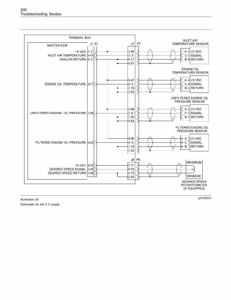
200Troubleshooting Section
g01065037Illustration 20Schematic for the 5 V supply
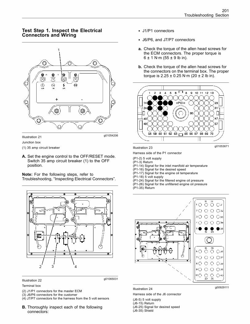
201Troubleshooting Section
Test Step 1. Inspect the ElectricalConnectors and Wiring
g01054206Illustration 21Junction box
(1) 35 amp circuit breaker
A. Set the engine control to the OFF/RESET mode.Switch 35 amp circuit breaker (1) to the OFFposition.
Note: For the following steps, refer toTroubleshooting, “Inspecting Electrical Connectors”.
g01065031Illustration 22
Terminal box
(2) J1/P1 connectors for the master ECM(3) J6/P6 connectors for the customer(4) J7/P7 connectors for the harness from the 5 volt sensors
B. Thoroughly inspect each of the followingconnectors:
• J1/P1 connectors
• J6/P6, and J7/P7 connectors
a. Check the torque of the allen head screws forthe ECM connectors. The proper torque is6 ± 1 N·m (55 ± 9 lb in).
b. Check the torque of the allen head screws forthe connectors on the terminal box. The propertorque is 2.25 ± 0.25 N·m (20 ± 2 lb in).
g01053671Illustration 23Harness side of the P1 connector
(P1-2) 5 volt supply(P1-3) Return(P1-14) Signal for the inlet manifold air temperature(P1-16) Signal for the desired speed(P1-17) Signal for the engine oil temperature(P1-18) 5 volt supply(P1-24) Signal for the filtered engine oil pressure(P1-26) Signal for the unfiltered engine oil pressure(P1-35) Return
g00929111Illustration 24Harness side of the J6 connector
(J6-5) 5 volt supply(J6-15) Return(J6-25) Signal for desired speed(J6-35) Shield
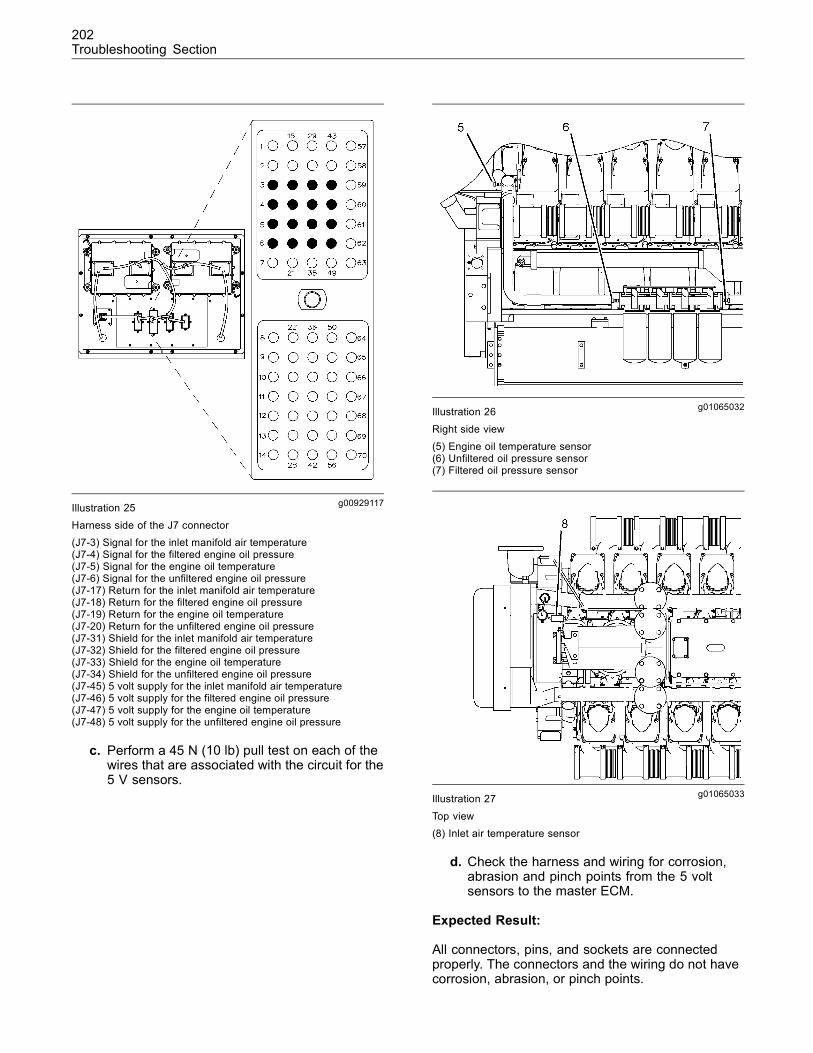
202Troubleshooting Section
g00929117Illustration 25
Harness side of the J7 connector(J7-3) Signal for the inlet manifold air temperature(J7-4) Signal for the filtered engine oil pressure(J7-5) Signal for the engine oil temperature(J7-6) Signal for the unfiltered engine oil pressure(J7-17) Return for the inlet manifold air temperature(J7-18) Return for the filtered engine oil pressure(J7-19) Return for the engine oil temperature(J7-20) Return for the unfiltered engine oil pressure(J7-31) Shield for the inlet manifold air temperature(J7-32) Shield for the filtered engine oil pressure(J7-33) Shield for the engine oil temperature(J7-34) Shield for the unfiltered engine oil pressure(J7-45) 5 volt supply for the inlet manifold air temperature(J7-46) 5 volt supply for the filtered engine oil pressure(J7-47) 5 volt supply for the engine oil temperature(J7-48) 5 volt supply for the unfiltered engine oil pressure
c. Perform a 45 N (10 lb) pull test on each of thewires that are associated with the circuit for the5 V sensors.
g01065032Illustration 26
Right side view(5) Engine oil temperature sensor(6) Unfiltered oil pressure sensor(7) Filtered oil pressure sensor
g01065033Illustration 27
Top view(8) Inlet air temperature sensor
d. Check the harness and wiring for corrosion,abrasion and pinch points from the 5 voltsensors to the master ECM.
Expected Result:
All connectors, pins, and sockets are connectedproperly. The connectors and the wiring do not havecorrosion, abrasion, or pinch points.
203Troubleshooting Section
Results:
• OK – All connectors, pins, and sockets areconnected properly. The connectors and the wiringdo not have corrosion, abrasion, or pinch points.The components are in good condition with properconnections. Proceed to Test Step 2.
• Not OK – At least one of the connectors, pins, orsockets are not connected properly. At least oneof the connectors and the wiring has corrosion,abrasion, and/or pinch points.
Repair: Perform the necessary repairs and/orreplace parts, if necessary.
STOP.
Test Step 2. Check for Diagnostic Codes
A. Connect Cat ET to the service tool connector.Refer to Troubleshooting, “Electronic ServiceTools”.
B. Rotate the “DESIRED SPEED” potentiometer(if equipped) counterclockwise to the minimumspeed position.
C. Switch the 35 amp circuit breaker ON. Set theengine control to the STOP mode.
D. Observe the “Active Diagnostic” screen on Cat ET.Wait at least 30 seconds so that any codes maybecome activated. Look for these codes:
• 262-03 5 Volt Sensor DC Power Supply shortto +batt
• 262-04 5 Volt Sensor DC Power Supply shortto ground
E. Observe the “Logged Diagnostic” screen on CatET. Look for the same codes.
Expected Result:
The 262-03 code or the 262-04 code is not activeor logged.
Results:
• No codes – There are no active codes or loggedcodes. Proceed to Test Step 3.
• Active code – The 262-03 code or the 262-04code is active. Proceed to Test Step 5.
• Logged code – The 262-03 code or the 262-04code is not active. However, there is at least onelogged code for the 5 volt sensor supply.
Repair: There may be a problem with the wiringand/or a connector. Refer to Troubleshooting,“Inspecting Electrical Connectors”.
Verify that the wiring and/or connectors are OK.Check for diagnostic codes again. Proceed to TestStep 3, if necessary.
Test Step 3. Check the Analog SpeedCircuit
Note: If the engine is not equipped with a “DESIREDSPEED” potentiometer, proceed to Test Step 9.
A. Rotate the “DESIRED SPEED” potentiometer(if equipped) clockwise to the maximum speedposition.
Expected Result:
The 262-03 code or the 262-04 code is not active.
Results:
• No codes – Rotating the “DESIRED SPEED”potentiometer clockwise to the maximum speedposition did not cause an active code. The +5 Vsensor voltage supply is operating correctly at thistime. Resume normal operation. STOP.
• Active code – Rotating the “DESIRED SPEED”potentiometer clockwise to the maximum speedposition caused an active code. There is a problemwith the analog speed circuit. Proceed to Test Step4.
Test Step 4. Check the Wiring for the“DESIRED SPEED” Potentiometer
A. Set the engine control to the OFF/RESET mode.Switch the 35 amp circuit breaker OFF.
B. Label the wiring that is connected to the“DESIRED SPEED” potentiometer. Disconnect thewiring from the “DESIRED SPEED” potentiometer.
C. Disconnect the P1 connector from the masterECM.
D. Measure the resistance between terminals P1-16and P1-69.
Expected Result:
The resistance is greater than 20,000 Ohms.
Results:
• OK – The resistance is greater than 20,000Ohms. The wiring for the “DESIRED SPEED”potentiometer appears to be OK.
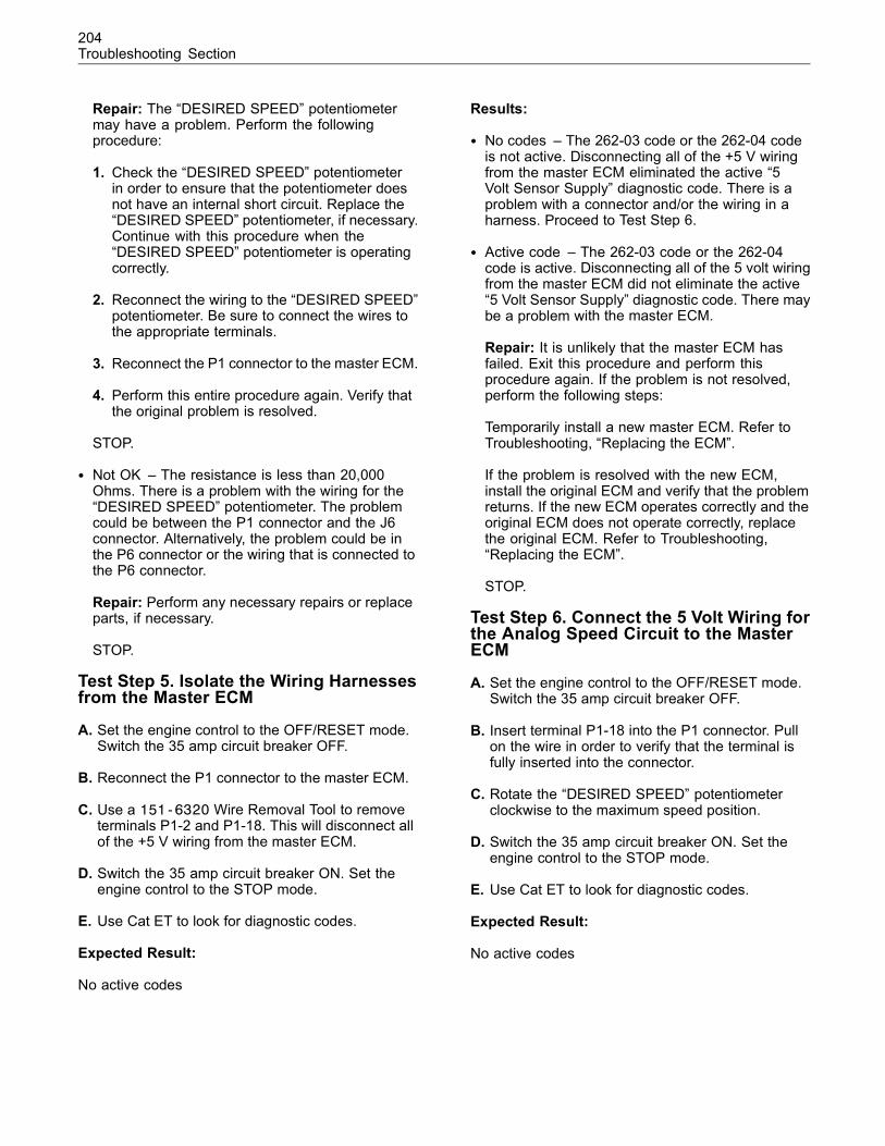
204Troubleshooting Section
Repair: The “DESIRED SPEED” potentiometermay have a problem. Perform the followingprocedure:
1. Check the “DESIRED SPEED” potentiometerin order to ensure that the potentiometer doesnot have an internal short circuit. Replace the“DESIRED SPEED” potentiometer, if necessary.Continue with this procedure when the“DESIRED SPEED” potentiometer is operatingcorrectly.
2. Reconnect the wiring to the “DESIRED SPEED”potentiometer. Be sure to connect the wires tothe appropriate terminals.
3. Reconnect the P1 connector to the master ECM.
4. Perform this entire procedure again. Verify thatthe original problem is resolved.
STOP.
• Not OK – The resistance is less than 20,000Ohms. There is a problem with the wiring for the“DESIRED SPEED” potentiometer. The problemcould be between the P1 connector and the J6connector. Alternatively, the problem could be inthe P6 connector or the wiring that is connected tothe P6 connector.
Repair: Perform any necessary repairs or replaceparts, if necessary.
STOP.
Test Step 5. Isolate the Wiring Harnessesfrom the Master ECM
A. Set the engine control to the OFF/RESET mode.Switch the 35 amp circuit breaker OFF.
B. Reconnect the P1 connector to the master ECM.
C. Use a 151-6320 Wire Removal Tool to removeterminals P1-2 and P1-18. This will disconnect allof the +5 V wiring from the master ECM.
D. Switch the 35 amp circuit breaker ON. Set theengine control to the STOP mode.
E. Use Cat ET to look for diagnostic codes.
Expected Result:
No active codes
Results:
• No codes – The 262-03 code or the 262-04 codeis not active. Disconnecting all of the +5 V wiringfrom the master ECM eliminated the active “5Volt Sensor Supply” diagnostic code. There is aproblem with a connector and/or the wiring in aharness. Proceed to Test Step 6.
• Active code – The 262-03 code or the 262-04code is active. Disconnecting all of the 5 volt wiringfrom the master ECM did not eliminate the active“5 Volt Sensor Supply” diagnostic code. There maybe a problem with the master ECM.
Repair: It is unlikely that the master ECM hasfailed. Exit this procedure and perform thisprocedure again. If the problem is not resolved,perform the following steps:
Temporarily install a new master ECM. Refer toTroubleshooting, “Replacing the ECM”.
If the problem is resolved with the new ECM,install the original ECM and verify that the problemreturns. If the new ECM operates correctly and theoriginal ECM does not operate correctly, replacethe original ECM. Refer to Troubleshooting,“Replacing the ECM”.
STOP.
Test Step 6. Connect the 5 Volt Wiring forthe Analog Speed Circuit to the MasterECM
A. Set the engine control to the OFF/RESET mode.Switch the 35 amp circuit breaker OFF.
B. Insert terminal P1-18 into the P1 connector. Pullon the wire in order to verify that the terminal isfully inserted into the connector.
C. Rotate the “DESIRED SPEED” potentiometerclockwise to the maximum speed position.
D. Switch the 35 amp circuit breaker ON. Set theengine control to the STOP mode.
E. Use Cat ET to look for diagnostic codes.
Expected Result:
No active codes
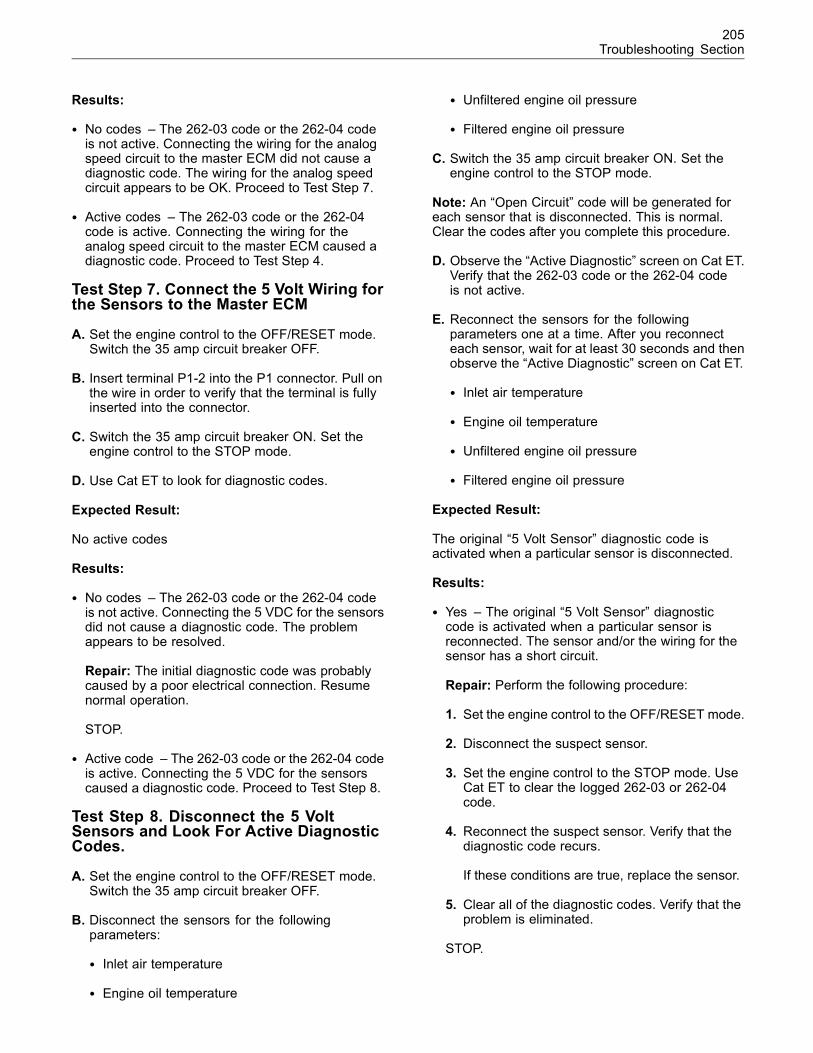
205Troubleshooting Section
Results:
• No codes – The 262-03 code or the 262-04 codeis not active. Connecting the wiring for the analogspeed circuit to the master ECM did not cause adiagnostic code. The wiring for the analog speedcircuit appears to be OK. Proceed to Test Step 7.
• Active codes – The 262-03 code or the 262-04code is active. Connecting the wiring for theanalog speed circuit to the master ECM caused adiagnostic code. Proceed to Test Step 4.
Test Step 7. Connect the 5 Volt Wiring forthe Sensors to the Master ECM
A. Set the engine control to the OFF/RESET mode.Switch the 35 amp circuit breaker OFF.
B. Insert terminal P1-2 into the P1 connector. Pull onthe wire in order to verify that the terminal is fullyinserted into the connector.
C. Switch the 35 amp circuit breaker ON. Set theengine control to the STOP mode.
D. Use Cat ET to look for diagnostic codes.
Expected Result:
No active codes
Results:
• No codes – The 262-03 code or the 262-04 codeis not active. Connecting the 5 VDC for the sensorsdid not cause a diagnostic code. The problemappears to be resolved.
Repair: The initial diagnostic code was probablycaused by a poor electrical connection. Resumenormal operation.
STOP.
• Active code – The 262-03 code or the 262-04 codeis active. Connecting the 5 VDC for the sensorscaused a diagnostic code. Proceed to Test Step 8.
Test Step 8. Disconnect the 5 VoltSensors and Look For Active DiagnosticCodes.
A. Set the engine control to the OFF/RESET mode.Switch the 35 amp circuit breaker OFF.
B. Disconnect the sensors for the followingparameters:
• Inlet air temperature
• Engine oil temperature
• Unfiltered engine oil pressure
• Filtered engine oil pressure
C. Switch the 35 amp circuit breaker ON. Set theengine control to the STOP mode.
Note: An “Open Circuit” code will be generated foreach sensor that is disconnected. This is normal.Clear the codes after you complete this procedure.
D. Observe the “Active Diagnostic” screen on Cat ET.Verify that the 262-03 code or the 262-04 codeis not active.
E. Reconnect the sensors for the followingparameters one at a time. After you reconnecteach sensor, wait for at least 30 seconds and thenobserve the “Active Diagnostic” screen on Cat ET.
• Inlet air temperature
• Engine oil temperature
• Unfiltered engine oil pressure
• Filtered engine oil pressure
Expected Result:
The original “5 Volt Sensor” diagnostic code isactivated when a particular sensor is disconnected.
Results:
• Yes – The original “5 Volt Sensor” diagnosticcode is activated when a particular sensor isreconnected. The sensor and/or the wiring for thesensor has a short circuit.
Repair: Perform the following procedure:
1. Set the engine control to the OFF/RESET mode.
2. Disconnect the suspect sensor.
3. Set the engine control to the STOP mode. UseCat ET to clear the logged 262-03 or 262-04code.
4. Reconnect the suspect sensor. Verify that thediagnostic code recurs.
If these conditions are true, replace the sensor.
5. Clear all of the diagnostic codes. Verify that theproblem is eliminated.
STOP.
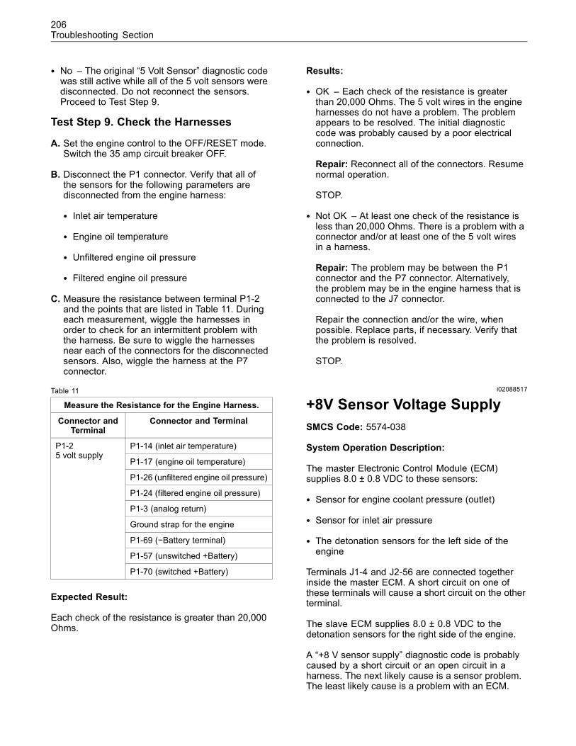
206Troubleshooting Section
• No – The original “5 Volt Sensor” diagnostic codewas still active while all of the 5 volt sensors weredisconnected. Do not reconnect the sensors.Proceed to Test Step 9.
Test Step 9. Check the Harnesses
A. Set the engine control to the OFF/RESET mode.Switch the 35 amp circuit breaker OFF.
B. Disconnect the P1 connector. Verify that all ofthe sensors for the following parameters aredisconnected from the engine harness:
• Inlet air temperature
• Engine oil temperature
• Unfiltered engine oil pressure
• Filtered engine oil pressure
C. Measure the resistance between terminal P1-2and the points that are listed in Table 11. Duringeach measurement, wiggle the harnesses inorder to check for an intermittent problem withthe harness. Be sure to wiggle the harnessesnear each of the connectors for the disconnectedsensors. Also, wiggle the harness at the P7connector.
Table 11
Measure the Resistance for the Engine Harness.
Connector andTerminal
Connector and Terminal
P1-14 (inlet air temperature)
P1-17 (engine oil temperature)
P1-26 (unfiltered engine oil pressure)
P1-24 (filtered engine oil pressure)
P1-3 (analog return)
Ground strap for the engine
P1-69 (−Battery terminal)
P1-57 (unswitched +Battery)
P1-25 volt supply
P1-70 (switched +Battery)
Expected Result:
Each check of the resistance is greater than 20,000Ohms.
Results:
• OK – Each check of the resistance is greaterthan 20,000 Ohms. The 5 volt wires in the engineharnesses do not have a problem. The problemappears to be resolved. The initial diagnosticcode was probably caused by a poor electricalconnection.
Repair: Reconnect all of the connectors. Resumenormal operation.
STOP.
• Not OK – At least one check of the resistance isless than 20,000 Ohms. There is a problem with aconnector and/or at least one of the 5 volt wiresin a harness.
Repair: The problem may be between the P1connector and the P7 connector. Alternatively,the problem may be in the engine harness that isconnected to the J7 connector.
Repair the connection and/or the wire, whenpossible. Replace parts, if necessary. Verify thatthe problem is resolved.
STOP.
i02088517
+8V Sensor Voltage SupplySMCS Code: 5574-038
System Operation Description:
The master Electronic Control Module (ECM)supplies 8.0 ± 0.8 VDC to these sensors:
• Sensor for engine coolant pressure (outlet)
• Sensor for inlet air pressure
• The detonation sensors for the left side of theengine
Terminals J1-4 and J2-56 are connected togetherinside the master ECM. A short circuit on one ofthese terminals will cause a short circuit on the otherterminal.
The slave ECM supplies 8.0 ± 0.8 VDC to thedetonation sensors for the right side of the engine.
A “+8 V sensor supply” diagnostic code is probablycaused by a short circuit or an open circuit in aharness. The next likely cause is a sensor problem.The least likely cause is a problem with an ECM.

207Troubleshooting Section
Logged diagnostic codes provide a historical record.Before you begin this procedure, use the CaterpillarElectronic Technician (ET) to print the logged codesto a file.
This troubleshooting procedure may generateadditional diagnostic codes. Keep your mind oncorrecting the cause of the original diagnostic code.Clear the diagnostic codes after the problem isresolved.
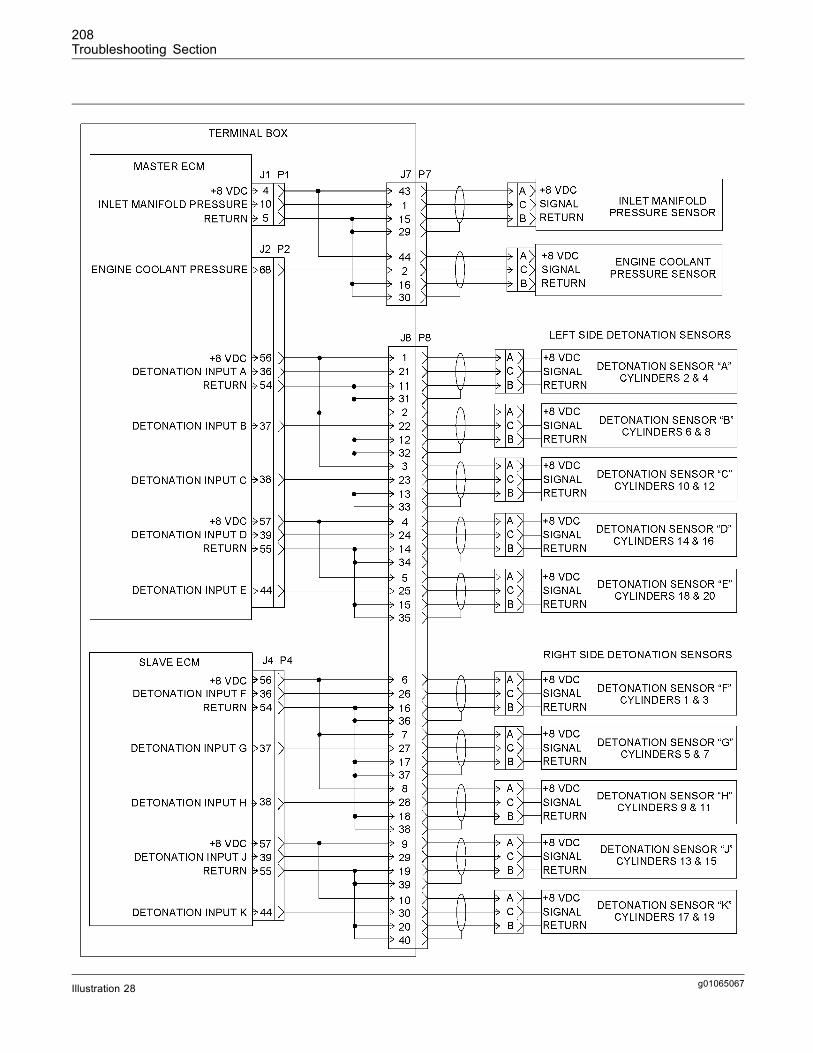
208Troubleshooting Section
g01065067Illustration 28
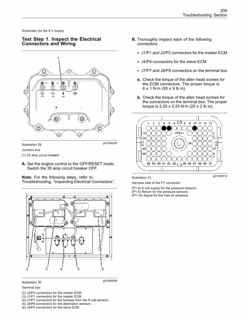
209Troubleshooting Section
Schematic for the 8 V supply
Test Step 1. Inspect the ElectricalConnectors and Wiring
g01054206Illustration 29
Junction box(1) 35 amp circuit breaker
A. Set the engine control to the OFF/RESET mode.Switch the 35 amp circuit breaker OFF.
Note: For the following steps, refer toTroubleshooting, “Inspecting Electrical Connectors”.
g01065068Illustration 30Terminal box
(2) J2/P2 connectors for the master ECM(3) J1/P1 connectors for the master ECM(4) J7/P7 connectors for the harness from the 8 volt sensors(5) J8/P8 connectors for the detonation sensors(6) J4/P4 connectors for the slave ECM
B. Thoroughly inspect each of the followingconnectors:
• J1/P1 and J2/P2 connectors for the master ECM
• J4/P4 connectors for the slave ECM
• J7/P7 and J8/P8 connectors on the terminal box
a. Check the torque of the allen head screws forthe ECM connectors. The proper torque is6 ± 1 N·m (55 ± 9 lb in).
b. Check the torque of the allen head screws forthe connectors on the terminal box. The propertorque is 2.25 ± 0.25 N·m (20 ± 2 lb in).
g01065914Illustration 31Harness side of the P1 connector(P1-4) 8 volt supply for the pressure sensors(P1-5) Return for the pressure sensors(P1-10) Signal for the inlet air pressure
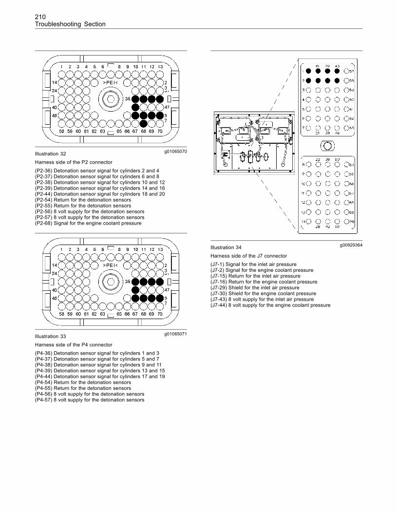
210Troubleshooting Section
g01065070Illustration 32Harness side of the P2 connector
(P2-36) Detonation sensor signal for cylinders 2 and 4(P2-37) Detonation sensor signal for cylinders 6 and 8(P2-38) Detonation sensor signal for cylinders 10 and 12(P2-39) Detonation sensor signal for cylinders 14 and 16(P2-44) Detonation sensor signal for cylinders 18 and 20(P2-54) Return for the detonation sensors(P2-55) Return for the detonation sensors(P2-56) 8 volt supply for the detonation sensors(P2-57) 8 volt supply for the detonation sensors(P2-68) Signal for the engine coolant pressure
g01065071Illustration 33Harness side of the P4 connector(P4-36) Detonation sensor signal for cylinders 1 and 3(P4-37) Detonation sensor signal for cylinders 5 and 7(P4-38) Detonation sensor signal for cylinders 9 and 11(P4-39) Detonation sensor signal for cylinders 13 and 15(P4-44) Detonation sensor signal for cylinders 17 and 19(P4-54) Return for the detonation sensors(P4-55) Return for the detonation sensors(P4-56) 8 volt supply for the detonation sensors(P4-57) 8 volt supply for the detonation sensors
g00929364Illustration 34
Harness side of the J7 connector(J7-1) Signal for the inlet air pressure(J7-2) Signal for the engine coolant pressure(J7-15) Return for the inlet air pressure(J7-16) Return for the engine coolant pressure(J7-29) Shield for the inlet air pressure(J7-30) Shield for the engine coolant pressure(J7-43) 8 volt supply for the inlet air pressure(J7-44) 8 volt supply for the engine coolant pressure
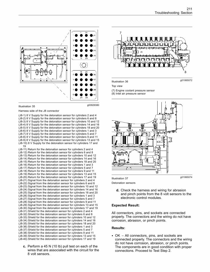
211Troubleshooting Section
g00929380Illustration 35
Harness side of the J8 connector(J8-1) 8 V Supply for the detonation sensor for cylinders 2 and 4(J8-2) 8 V Supply for the detonation sensor for cylinders 6 and 8(J8-3) 8 V Supply for the detonation sensor for cylinders 10 and 12(J8-4) 8 V Supply for the detonation sensor for cylinders 14 and 16(J8-5) 8 V Supply for the detonation sensor for cylinders 18 and 20(J8-6) 8 V Supply for the detonation sensor for cylinders 1 and 3(J8-7) 8 V Supply for the detonation sensor for cylinders 5 and 7(J8-8) 8 V Supply for the detonation sensor for cylinders 9 and 11(J8-9) 8 V Supply for the detonation sensor for cylinders 13 and 15(J8-10) 8 V Supply for the detonation sensor for cylinders 17 and
19(J8-11) Return for the detonation sensor for cylinders 2 and 4(J8-12) Return for the detonation sensor for cylinders 6 and 8(J8-13) Return for the detonation sensor for cylinders 10 and 12(J8-14) Return for the detonation sensor for cylinders 14 and 16(J8-15) Return for the detonation sensor for cylinders 18 and 20(J8-16) Return for the detonation sensor for cylinders 1 and 3(J8-17) Return for the detonation sensor for cylinders 5 and 7(J8-18) Return for the detonation sensor for cylinders 9 and 11(J8-19) Return for the detonation sensor for cylinders 13 and 15(J8-20) Return for the detonation sensor for cylinders 17 and 19(J8-21) Signal from the detonation sensor for cylinders 2 and 4(J8-22) Signal from the detonation sensor for cylinders 6 and 8(J8-23) Signal from the detonation sensor for cylinders 10 and 12(J8-24) Signal from the detonation sensor for cylinders 14 and 16(J8-25) Signal from the detonation sensor for cylinders 18 and 20(J8-26) Signal from the detonation sensor for cylinders 1 and 3(J8-27) Signal from the detonation sensor for cylinders 5 and 7(J8-28) Signal from the detonation sensor for cylinders 9 and 11(J8-29) Signal from the detonation sensor for cylinders 13 and 15(J8-30) Signal from the detonation sensor for cylinders 17 and 19(J8-31) Shield for the detonation sensor for cylinders 2 and 4(J8-32) Shield for the detonation sensor for cylinders 6 and 8(J8-33) Shield for the detonation sensor for cylinders 10 and 12(J8-34) Shield for the detonation sensor for cylinders 14 and 16(J8-35) Shield for the detonation sensor for cylinders 18 and 20(J8-36) Shield for the detonation sensor for cylinders 1 and 3(J8-37) Shield for the detonation sensor for cylinders 5 and 7(J8-38) Shield for the detonation sensor for cylinders 9 and 11(J8-39) Shield for the detonation sensor for cylinders 13 and 15(J8-40) Shield for the detonation sensor for cylinders 17 and 19
c. Perform a 45 N (10 lb) pull test on each of thewires that are associated with the circuit for the8 volt sensors.
g01065072Illustration 36Top view
(7) Engine coolant pressure sensor(8) Inlet air pressure sensor
g01065074Illustration 37Detonation sensors
d. Check the harness and wiring for abrasionand pinch points from the 8 volt sensors to theelectronic control modules.
Expected Result:
All connectors, pins, and sockets are connectedproperly. The connectors and the wiring do not havecorrosion, abrasion, or pinch points.
Results:
• OK – All connectors, pins, and sockets areconnected properly. The connectors and the wiringdo not have corrosion, abrasion, or pinch points.The components are in good condition with properconnections. Proceed to Test Step 2.
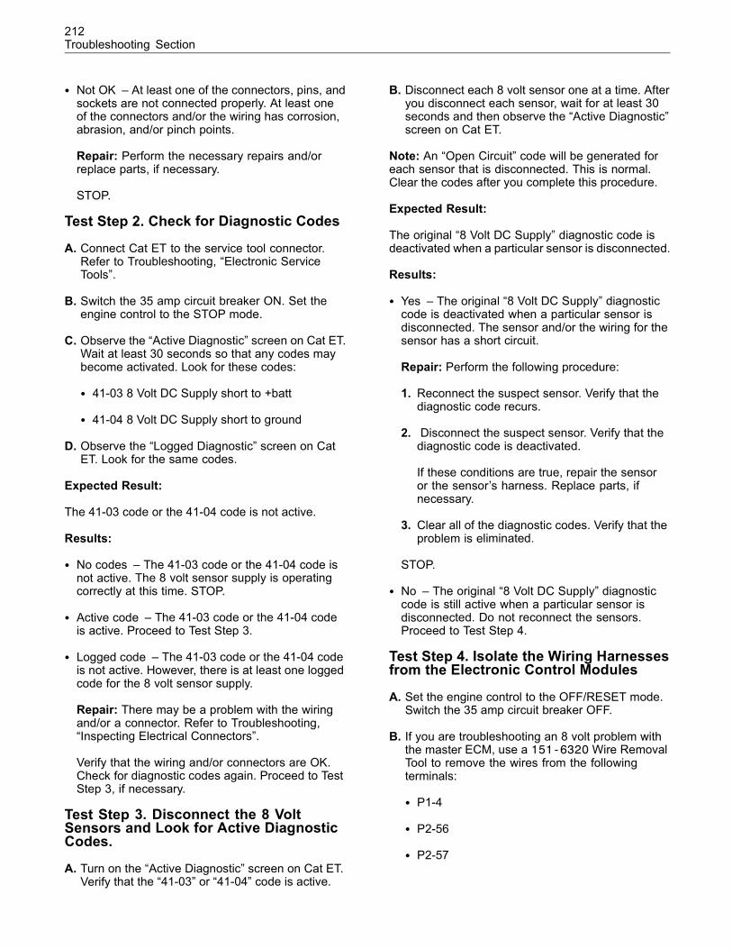
212Troubleshooting Section
• Not OK – At least one of the connectors, pins, andsockets are not connected properly. At least oneof the connectors and/or the wiring has corrosion,abrasion, and/or pinch points.
Repair: Perform the necessary repairs and/orreplace parts, if necessary.
STOP.
Test Step 2. Check for Diagnostic Codes
A. Connect Cat ET to the service tool connector.Refer to Troubleshooting, “Electronic ServiceTools”.
B. Switch the 35 amp circuit breaker ON. Set theengine control to the STOP mode.
C. Observe the “Active Diagnostic” screen on Cat ET.Wait at least 30 seconds so that any codes maybecome activated. Look for these codes:
• 41-03 8 Volt DC Supply short to +batt
• 41-04 8 Volt DC Supply short to ground
D. Observe the “Logged Diagnostic” screen on CatET. Look for the same codes.
Expected Result:
The 41-03 code or the 41-04 code is not active.
Results:
• No codes – The 41-03 code or the 41-04 code isnot active. The 8 volt sensor supply is operatingcorrectly at this time. STOP.
• Active code – The 41-03 code or the 41-04 codeis active. Proceed to Test Step 3.
• Logged code – The 41-03 code or the 41-04 codeis not active. However, there is at least one loggedcode for the 8 volt sensor supply.
Repair: There may be a problem with the wiringand/or a connector. Refer to Troubleshooting,“Inspecting Electrical Connectors”.
Verify that the wiring and/or connectors are OK.Check for diagnostic codes again. Proceed to TestStep 3, if necessary.
Test Step 3. Disconnect the 8 VoltSensors and Look for Active DiagnosticCodes.
A. Turn on the “Active Diagnostic” screen on Cat ET.Verify that the “41-03” or “41-04” code is active.
B. Disconnect each 8 volt sensor one at a time. Afteryou disconnect each sensor, wait for at least 30seconds and then observe the “Active Diagnostic”screen on Cat ET.
Note: An “Open Circuit” code will be generated foreach sensor that is disconnected. This is normal.Clear the codes after you complete this procedure.
Expected Result:
The original “8 Volt DC Supply” diagnostic code isdeactivated when a particular sensor is disconnected.
Results:
• Yes – The original “8 Volt DC Supply” diagnosticcode is deactivated when a particular sensor isdisconnected. The sensor and/or the wiring for thesensor has a short circuit.
Repair: Perform the following procedure:
1. Reconnect the suspect sensor. Verify that thediagnostic code recurs.
2. Disconnect the suspect sensor. Verify that thediagnostic code is deactivated.
If these conditions are true, repair the sensoror the sensor’s harness. Replace parts, ifnecessary.
3. Clear all of the diagnostic codes. Verify that theproblem is eliminated.
STOP.
• No – The original “8 Volt DC Supply” diagnosticcode is still active when a particular sensor isdisconnected. Do not reconnect the sensors.Proceed to Test Step 4.
Test Step 4. Isolate the Wiring Harnessesfrom the Electronic Control Modules
A. Set the engine control to the OFF/RESET mode.Switch the 35 amp circuit breaker OFF.
B. If you are troubleshooting an 8 volt problem withthe master ECM, use a 151-6320Wire RemovalTool to remove the wires from the followingterminals:
• P1-4
• P2-56
• P2-57
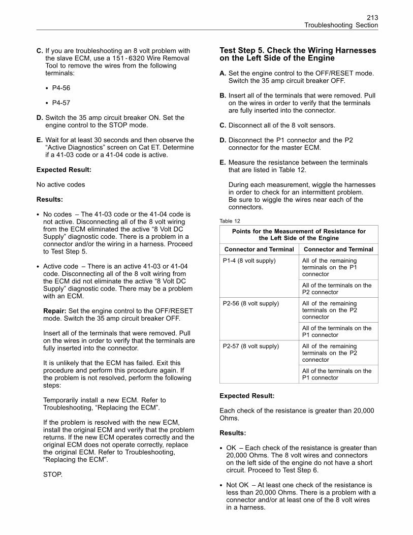
213Troubleshooting Section
C. If you are troubleshooting an 8 volt problem withthe slave ECM, use a 151-6320 Wire RemovalTool to remove the wires from the followingterminals:
• P4-56
• P4-57
D. Switch the 35 amp circuit breaker ON. Set theengine control to the STOP mode.
E. Wait for at least 30 seconds and then observe the“Active Diagnostics” screen on Cat ET. Determineif a 41-03 code or a 41-04 code is active.
Expected Result:
No active codes
Results:
• No codes – The 41-03 code or the 41-04 code isnot active. Disconnecting all of the 8 volt wiringfrom the ECM eliminated the active “8 Volt DCSupply” diagnostic code. There is a problem in aconnector and/or the wiring in a harness. Proceedto Test Step 5.
• Active code – There is an active 41-03 or 41-04code. Disconnecting all of the 8 volt wiring fromthe ECM did not eliminate the active “8 Volt DCSupply” diagnostic code. There may be a problemwith an ECM.
Repair: Set the engine control to the OFF/RESETmode. Switch the 35 amp circuit breaker OFF.
Insert all of the terminals that were removed. Pullon the wires in order to verify that the terminals arefully inserted into the connector.
It is unlikely that the ECM has failed. Exit thisprocedure and perform this procedure again. Ifthe problem is not resolved, perform the followingsteps:
Temporarily install a new ECM. Refer toTroubleshooting, “Replacing the ECM”.
If the problem is resolved with the new ECM,install the original ECM and verify that the problemreturns. If the new ECM operates correctly and theoriginal ECM does not operate correctly, replacethe original ECM. Refer to Troubleshooting,“Replacing the ECM”.
STOP.
Test Step 5. Check the Wiring Harnesseson the Left Side of the Engine
A. Set the engine control to the OFF/RESET mode.Switch the 35 amp circuit breaker OFF.
B. Insert all of the terminals that were removed. Pullon the wires in order to verify that the terminalsare fully inserted into the connector.
C. Disconnect all of the 8 volt sensors.
D. Disconnect the P1 connector and the P2connector for the master ECM.
E. Measure the resistance between the terminalsthat are listed in Table 12.
During each measurement, wiggle the harnessesin order to check for an intermittent problem.Be sure to wiggle the wires near each of theconnectors.
Table 12
Points for the Measurement of Resistance forthe Left Side of the Engine
Connector and Terminal Connector and Terminal
All of the remainingterminals on the P1connector
P1-4 (8 volt supply)
All of the terminals on theP2 connector
All of the remainingterminals on the P2connector
P2-56 (8 volt supply)
All of the terminals on theP1 connector
All of the remainingterminals on the P2connector
P2-57 (8 volt supply)
All of the terminals on theP1 connector
Expected Result:
Each check of the resistance is greater than 20,000Ohms.
Results:
• OK – Each check of the resistance is greater than20,000 Ohms. The 8 volt wires and connectorson the left side of the engine do not have a shortcircuit. Proceed to Test Step 6.
• Not OK – At least one check of the resistance isless than 20,000 Ohms. There is a problem with aconnector and/or at least one of the 8 volt wiresin a harness.
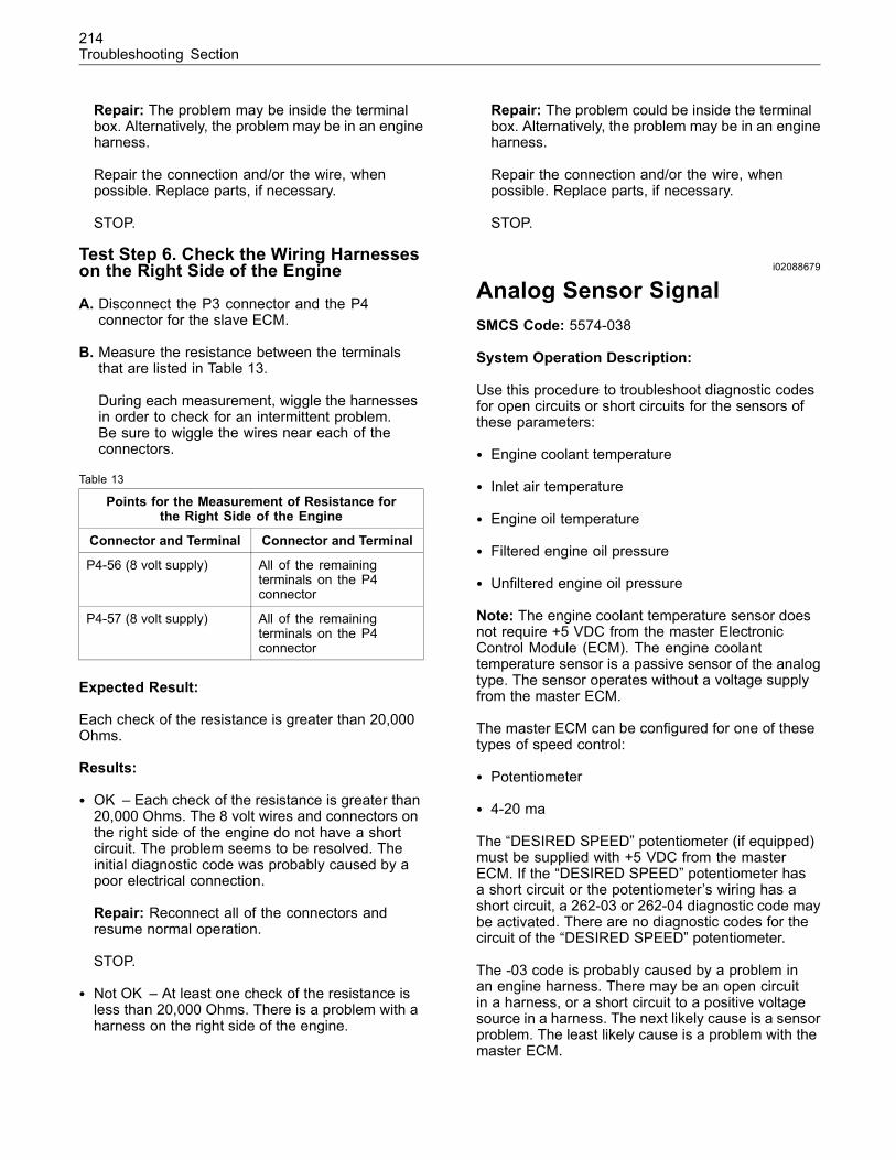
214Troubleshooting Section
Repair: The problem may be inside the terminalbox. Alternatively, the problem may be in an engineharness.
Repair the connection and/or the wire, whenpossible. Replace parts, if necessary.
STOP.
Test Step 6. Check the Wiring Harnesseson the Right Side of the Engine
A. Disconnect the P3 connector and the P4connector for the slave ECM.
B. Measure the resistance between the terminalsthat are listed in Table 13.
During each measurement, wiggle the harnessesin order to check for an intermittent problem.Be sure to wiggle the wires near each of theconnectors.
Table 13
Points for the Measurement of Resistance forthe Right Side of the Engine
Connector and Terminal Connector and Terminal
P4-56 (8 volt supply) All of the remainingterminals on the P4connector
P4-57 (8 volt supply) All of the remainingterminals on the P4connector
Expected Result:
Each check of the resistance is greater than 20,000Ohms.
Results:
• OK – Each check of the resistance is greater than20,000 Ohms. The 8 volt wires and connectors onthe right side of the engine do not have a shortcircuit. The problem seems to be resolved. Theinitial diagnostic code was probably caused by apoor electrical connection.
Repair: Reconnect all of the connectors andresume normal operation.
STOP.
• Not OK – At least one check of the resistance isless than 20,000 Ohms. There is a problem with aharness on the right side of the engine.
Repair: The problem could be inside the terminalbox. Alternatively, the problem may be in an engineharness.
Repair the connection and/or the wire, whenpossible. Replace parts, if necessary.
STOP.
i02088679
Analog Sensor SignalSMCS Code: 5574-038
System Operation Description:
Use this procedure to troubleshoot diagnostic codesfor open circuits or short circuits for the sensors ofthese parameters:
• Engine coolant temperature
• Inlet air temperature
• Engine oil temperature
• Filtered engine oil pressure
• Unfiltered engine oil pressure
Note: The engine coolant temperature sensor doesnot require +5 VDC from the master ElectronicControl Module (ECM). The engine coolanttemperature sensor is a passive sensor of the analogtype. The sensor operates without a voltage supplyfrom the master ECM.
The master ECM can be configured for one of thesetypes of speed control:
• Potentiometer
• 4-20 ma
The “DESIRED SPEED” potentiometer (if equipped)must be supplied with +5 VDC from the masterECM. If the “DESIRED SPEED” potentiometer hasa short circuit or the potentiometer’s wiring has ashort circuit, a 262-03 or 262-04 diagnostic code maybe activated. There are no diagnostic codes for thecircuit of the “DESIRED SPEED” potentiometer.
The -03 code is probably caused by a problem inan engine harness. There may be an open circuitin a harness, or a short circuit to a positive voltagesource in a harness. The next likely cause is a sensorproblem. The least likely cause is a problem with themaster ECM.
215Troubleshooting Section
The -04 code is probably caused by a short circuit toground in an engine harness. The next likely cause isa sensor problem. The least likely cause is a problemwith the master ECM.
Logged diagnostic codes provide a historical record.Before you begin this procedure, use the CaterpillarElectronic Technician (ET) to print the logged codesto a file.
This troubleshooting procedure may generateadditional diagnostic codes. Keep your mind oncorrecting the cause of the original diagnostic code.Clear the diagnostic code after the problem isresolved.
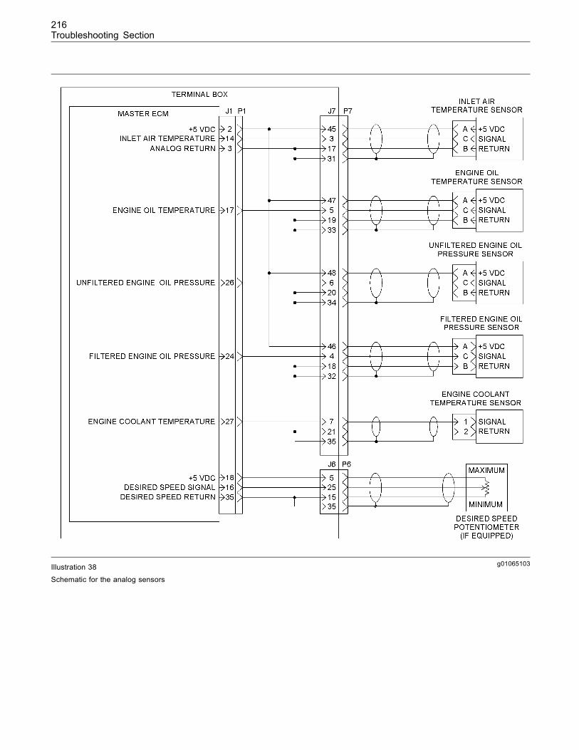
216Troubleshooting Section
g01065103Illustration 38
Schematic for the analog sensors

217Troubleshooting Section
Test Step 1. Inspect the ElectricalConnectors and Wiring
g01054206Illustration 39Junction box
(1) 35 amp circuit breaker
A. Set the engine control to the OFF/RESET mode.Switch 35 amp circuit breaker (1) to the OFFposition.
Note: For the following steps, refer toTroubleshooting, “Inspecting Electrical Connectors”.
g01065031Illustration 40
Terminal box
(2) J1/P1 connectors for the master ECM(3) J6/P6 connectors for the customer(4) J7/P7 connectors for the harness from the 5 volt sensors
B. Thoroughly inspect each of the followingconnectors:
• J1/P1 connectors
• J6/P6, and J7/P7 connectors
a. Check the torque of the allen head screws forthe ECM connectors. The proper torque is6 ± 1 N·m (55 ± 9 lb in).
b. Check the torque of the allen head screwsfor the terminal box’s connectors. The propertorque is 2.25 ± 0.25 N·m (20 ± 2 lb in).
g01065104Illustration 41Harness side of the P1 connector
(P1-2) 5 volt supply(P1-3) Return(P1-14) Signal for the inlet manifold air temperature(P1-16) Signal for the desired speed(P1-17) Signal for the engine oil temperature(P1-18) 5 volt supply(P1-24) Signal for the filtered engine oil pressure(P1-26) Signal for the unfiltered engine oil pressure(P1-27) Signal for the engine coolant temperature(P1-35) Return
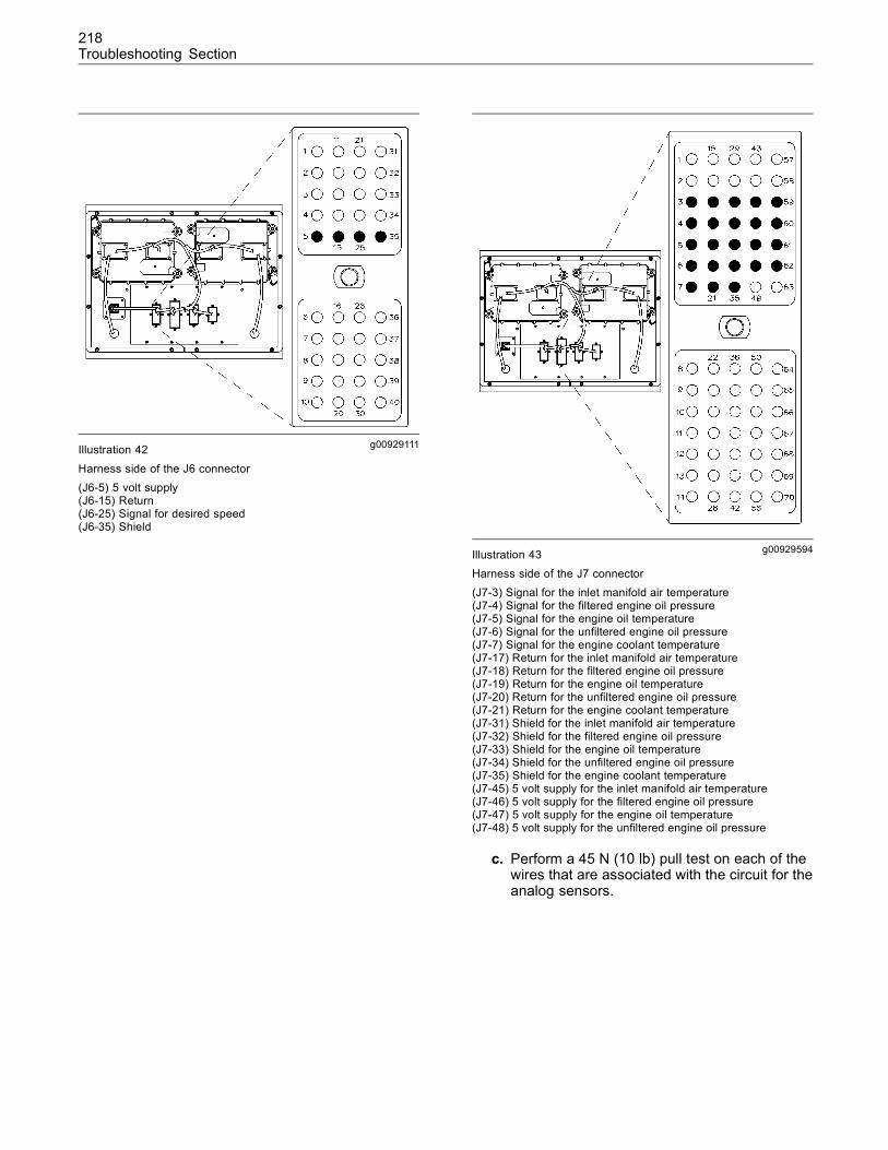
218Troubleshooting Section
g00929111Illustration 42
Harness side of the J6 connector(J6-5) 5 volt supply(J6-15) Return(J6-25) Signal for desired speed(J6-35) Shield
g00929594Illustration 43
Harness side of the J7 connector(J7-3) Signal for the inlet manifold air temperature(J7-4) Signal for the filtered engine oil pressure(J7-5) Signal for the engine oil temperature(J7-6) Signal for the unfiltered engine oil pressure(J7-7) Signal for the engine coolant temperature(J7-17) Return for the inlet manifold air temperature(J7-18) Return for the filtered engine oil pressure(J7-19) Return for the engine oil temperature(J7-20) Return for the unfiltered engine oil pressure(J7-21) Return for the engine coolant temperature(J7-31) Shield for the inlet manifold air temperature(J7-32) Shield for the filtered engine oil pressure(J7-33) Shield for the engine oil temperature(J7-34) Shield for the unfiltered engine oil pressure(J7-35) Shield for the engine coolant temperature(J7-45) 5 volt supply for the inlet manifold air temperature(J7-46) 5 volt supply for the filtered engine oil pressure(J7-47) 5 volt supply for the engine oil temperature(J7-48) 5 volt supply for the unfiltered engine oil pressure
c. Perform a 45 N (10 lb) pull test on each of thewires that are associated with the circuit for theanalog sensors.

219Troubleshooting Section
g01065032Illustration 44
Right side view(5) Engine oil temperature sensor(6) Unfiltered oil pressure sensor(7) Filtered oil pressure sensor
g01065110Illustration 45
Top view(8) Engine coolant temperature sensor(9) Engine coolant pressure sensor (outlet)
d. Check the harness and wiring for abrasion andfor pinch points from the analog sensors to themaster ECM.
Expected Result:
All connectors, pins, and sockets are connectedproperly. The connectors and the wiring do not havecorrosion, abrasion, or pinch points.
Results:
• OK – All connectors, pins, and sockets areconnected properly. The connectors and the wiringdo not have corrosion, abrasion, or pinch points.The components are in good condition with properconnections. Proceed to Test Step 2.
• Not OK – At least one of the connectors, pins,and/or sockets are not connected properly. Atleast one of the connectors and/or the wiring hascorrosion, abrasion, or pinch points.
Repair: Perform the necessary repairs and/orreplace parts, if necessary.
STOP.
Test Step 2. Check for Diagnostic Codesfor the Power Supply
A. Connect Cat ET to the service tool connector.Refer to Troubleshooting, “Electronic ServiceTools”.
B. Switch the 35 amp circuit breaker ON. Set theengine control to the STOP mode.
C. Observe the “Active Diagnostic” screen on ET.Allow a minimum of 30 seconds for any codes toactivate. Look for these codes:
• 262-03 5 Volt Sensor DC Power Supply shortto +batt
• 262-04 5 Volt Sensor DC Power Supply shortto ground
Expected Result:
There are no active “5 Volt Sensor DC Power Supply”diagnostic codes.
Results:
• No codes – There are no active “5 Volt Sensor DCPower Supply” diagnostic codes. Proceed to TestStep 3.
• Active code – There is an active “5 Volt Sensor DCPower Supply” diagnostic code. This procedure willnot work when this type of code is active.
Repair: Refer to Troubleshooting, “+5V SensorSupply”.
If necessary, return to this functional test in orderto troubleshoot the analog sensor after the “+5 VSensor Supply” diagnostic code has been resolved.
STOP.
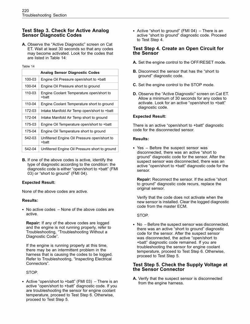
220Troubleshooting Section
Test Step 3. Check for Active AnalogSensor Diagnostic Codes
A. Observe the “Active Diagnostic” screen on CatET. Wait at least 30 seconds so that any codesmay become activated. Look for the codes thatare listed in Table 14:
Table 14
Analog Sensor Diagnostic Codes
100-03 Engine Oil Pressure open/short to +batt
100-04 Engine Oil Pressure short to ground
110-03 Engine Coolant Temperature open/short to+batt
110-04 Engine Coolant Temperature short to ground
172-03 Intake Manifold Air Temp open/short to +batt
172-04 Intake Manifold Air Temp short to ground
175-03 Engine Oil Temperature open/short to +batt
175-04 Engine Oil Temperature short to ground
542-03 Unfiltered Engine Oil Pressure open/short to+batt
542-04 Unfiltered Engine Oil Pressure short to ground
B. If one of the above codes is active, identify thetype of diagnostic according to the condition: thediagnostic code is either “open/short to +batt” (FMI03) or “short to ground” (FMI 04).
Expected Result:
None of the above codes are active.
Results:
• No active codes – None of the above codes areactive.
Repair: If any of the above codes are loggedand the engine is not running properly, refer toTroubleshooting, “Troubleshooting Without aDiagnostic Code”.
If the engine is running properly at this time,there may be an intermittent problem in theharness that is causing the codes to be logged.Refer to Troubleshooting, “Inspecting ElectricalConnectors”.
STOP.
• Active “open/short to +batt” (FMI 03) – There is anactive “open/short to +batt” diagnostic code. If youare troubleshooting the sensor for engine coolanttemperature, proceed to Test Step 6. Otherwise,proceed to Test Step 5.
• Active “short to ground” (FMI 04) – There is anactive “short to ground” diagnostic code. Proceedto Test Step 4.
Test Step 4. Create an Open Circuit forthe Sensor
A. Set the engine control to the OFF/RESET mode.
B. Disconnect the sensor that has the “short toground” diagnostic code.
C. Set the engine control to the STOP mode.
D. Observe the “Active Diagnostic” screen on Cat ET.Allow a minimum of 30 seconds for any codes toactivate. Look for an active “open/short to +batt”diagnostic code.
Expected Result:
There is an active “open/short to +batt” diagnosticcode for the disconnected sensor.
Results:
• Yes – Before the suspect sensor wasdisconnected, there was an active “short toground” diagnostic code for the sensor. After thesuspect sensor was disconnected, there was anactive “open/short to +batt” diagnostic code for thesensor.
Repair: Reconnect the sensor. If the active “shortto ground” diagnostic code recurs, replace theoriginal sensor.
Verify that the code does not activate when thenew sensor is installed. Clear the logged diagnosticcode from the master ECM.
STOP.
• No – Before the suspect sensor was disconnected,there was an active “short to ground” diagnosticcode for the sensor. After the suspect sensorwas disconnected, the active “open/short to+batt” diagnostic code remained. If you aretroubleshooting the sensor for engine coolanttemperature, proceed to Test Step 6. Otherwise,proceed to Test Step 5.
Test Step 5. Check the Supply Voltage atthe Sensor Connector
A. Verify that the suspect sensor is disconnectedfrom the engine harness.
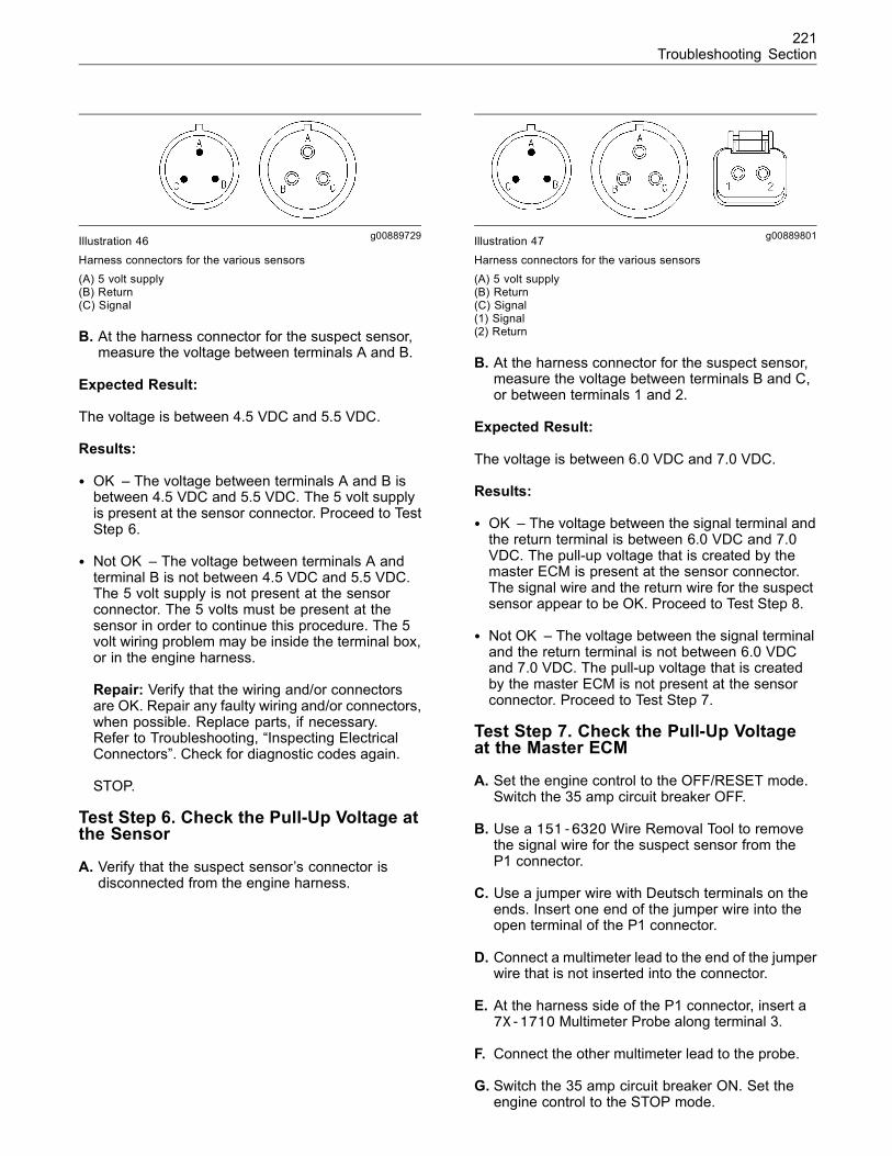
221Troubleshooting Section
g00889729Illustration 46Harness connectors for the various sensors(A) 5 volt supply(B) Return(C) Signal
B. At the harness connector for the suspect sensor,measure the voltage between terminals A and B.
Expected Result:
The voltage is between 4.5 VDC and 5.5 VDC.
Results:
• OK – The voltage between terminals A and B isbetween 4.5 VDC and 5.5 VDC. The 5 volt supplyis present at the sensor connector. Proceed to TestStep 6.
• Not OK – The voltage between terminals A andterminal B is not between 4.5 VDC and 5.5 VDC.The 5 volt supply is not present at the sensorconnector. The 5 volts must be present at thesensor in order to continue this procedure. The 5volt wiring problem may be inside the terminal box,or in the engine harness.
Repair: Verify that the wiring and/or connectorsare OK. Repair any faulty wiring and/or connectors,when possible. Replace parts, if necessary.Refer to Troubleshooting, “Inspecting ElectricalConnectors”. Check for diagnostic codes again.
STOP.
Test Step 6. Check the Pull-Up Voltage atthe Sensor
A. Verify that the suspect sensor’s connector isdisconnected from the engine harness.
g00889801Illustration 47Harness connectors for the various sensors(A) 5 volt supply(B) Return(C) Signal(1) Signal(2) Return
B. At the harness connector for the suspect sensor,measure the voltage between terminals B and C,or between terminals 1 and 2.
Expected Result:
The voltage is between 6.0 VDC and 7.0 VDC.
Results:
• OK – The voltage between the signal terminal andthe return terminal is between 6.0 VDC and 7.0VDC. The pull-up voltage that is created by themaster ECM is present at the sensor connector.The signal wire and the return wire for the suspectsensor appear to be OK. Proceed to Test Step 8.
• Not OK – The voltage between the signal terminaland the return terminal is not between 6.0 VDCand 7.0 VDC. The pull-up voltage that is createdby the master ECM is not present at the sensorconnector. Proceed to Test Step 7.
Test Step 7. Check the Pull-Up Voltageat the Master ECM
A. Set the engine control to the OFF/RESET mode.Switch the 35 amp circuit breaker OFF.
B. Use a 151-6320 Wire Removal Tool to removethe signal wire for the suspect sensor from theP1 connector.
C. Use a jumper wire with Deutsch terminals on theends. Insert one end of the jumper wire into theopen terminal of the P1 connector.
D. Connect a multimeter lead to the end of the jumperwire that is not inserted into the connector.
E. At the harness side of the P1 connector, insert a7X-1710 Multimeter Probe along terminal 3.
F. Connect the other multimeter lead to the probe.
G. Switch the 35 amp circuit breaker ON. Set theengine control to the STOP mode.
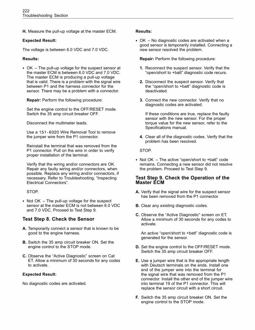
222Troubleshooting Section
H. Measure the pull-up voltage at the master ECM.
Expected Result:
The voltage is between 6.0 VDC and 7.0 VDC.
Results:
• OK – The pull-up voltage for the suspect sensor atthe master ECM is between 6.0 VDC and 7.0 VDC.The master ECM is producing a pull-up voltagethat is valid. There is a problem with the signal wirebetween P1 and the harness connector for thesensor. There may be a problem with a connector.
Repair: Perform the following procedure:
Set the engine control to the OFF/RESET mode.Switch the 35 amp circuit breaker OFF.
Disconnect the multimeter leads.
Use a 151-6320 Wire Removal Tool to removethe jumper wire from the P1 connector.
Reinstall the terminal that was removed from theP1 connector. Pull on the wire in order to verifyproper installation of the terminal.
Verify that the wiring and/or connectors are OK.Repair any faulty wiring and/or connectors, whenpossible. Replace any wiring and/or connectors, ifnecessary. Refer to Troubleshooting, “InspectingElectrical Connectors”.
STOP.
• Not OK – The pull-up voltage for the suspectsensor at the master ECM is not between 6.0 VDCand 7.0 VDC. Proceed to Test Step 9.
Test Step 8. Check the Sensor
A. Temporarily connect a sensor that is known to begood to the engine harness.
B. Switch the 35 amp circuit breaker ON. Set theengine control to the STOP mode.
C. Observe the “Active Diagnostic” screen on CatET. Allow a minimum of 30 seconds for any codesto activate.
Expected Result:
No diagnostic codes are activated.
Results:
• OK – No diagnostic codes are activated when agood sensor is temporarily installed. Connecting anew sensor resolved the problem.
Repair: Perform the following procedure:
1. Reconnect the suspect sensor. Verify that the“open/short to +batt” diagnostic code recurs.
2. Disconnect the suspect sensor. Verify thatthe “open/short to +batt” diagnostic code isdeactivated.
3. Connect the new connector. Verify that nodiagnostic codes are activated.
If these conditions are true, replace the faultysensor with the new sensor. For the propertorque value for the new sensor, refer to theSpecifications manual.
4. Clear all of the diagnostic codes. Verify that theproblem has been resolved.
STOP.
• Not OK – The active “open/short to +batt” coderemains. Connecting a new sensor did not resolvethe problem. Proceed to Test Step 9.
Test Step 9. Check the Operation of theMaster ECM
A. Verify that the signal wire for the suspect sensorhas been removed from the P1 connector.
B. Clear any existing diagnostic codes.
C. Observe the “Active Diagnostic” screen on ET.Allow a minimum of 30 seconds for any codes toactivate.
An active “open/short to +batt” diagnostic code isgenerated for the sensor.
D. Set the engine control to the OFF/RESET mode.Switch the 35 amp circuit breaker OFF.
E. Use a jumper wire that is the appropriate lengthwith Deutsch terminals on the ends. Install oneend of the jumper wire into the terminal forthe signal wire that was removed from the P1connector. Install the other end of the jumper wireinto terminal 19 of the P1 connector. This willreplace the sensor circuit with a short circuit.
F. Switch the 35 amp circuit breaker ON. Set theengine control to the STOP mode.
223Troubleshooting Section
G. Observe the “Active Diagnostic” screen on CatET. Allow a minimum of 30 seconds for any codesto activate.
An active “short to ground” diagnostic code isgenerated.
Expected Result:
Active “open/short to +batt” and “short to ground”diagnostic codes are generated according to theabove steps.
Results:
• OK – Active “open/short to +batt” and “short toground” diagnostic codes are generated accordingto the above steps. The master ECM is operatingcorrectly. The initial diagnostic code was probablycaused by a poor electrical connection.
Repair: Perform the following procedure:
Set the engine control to the OFF/RESET mode.Switch the 35 amp circuit breaker OFF.
Use a 151-6320 Wire Removal Tool to removethe jumper wire from the P1 connector.
Reinstall the terminal that was removed from theP1 connector. Pull on the wire in order to verifyproper installation of the terminal.
Resume normal operation.
STOP.
• Not OK – No active “open/short to +batt” and“short to ground” diagnostic codes were generated.The master ECM is not operating correctly.
Repair: It is unlikely that the master ECM hasfailed. Exit this procedure and perform this entireprocedure again. If the problem is not resolved,perform the following steps:
Temporarily install a new master ECM. Refer toTroubleshooting, “Replacing the ECM”.
If the problem is resolved with the new ECM,install the original ECM and verify that the problemreturns. If the new ECM operates correctly and theoriginal ECM does not operate correctly, replacethe ECM. Refer to Troubleshooting, “Replacingthe ECM”.
STOP.
i02088853
CAT Data LinkSMCS Code: 1901-038
System Operation Description:
The CAT data link is used to share informationbetween the following components:
• Master Electronic Control Module (ECM)
• Slave ECM
• Integrated Temperature Sensing Module (ITSM)
• Service tool
• Customer installed components
Illustration 48 shows the information that is sharedbetween the master ECM and the slave ECM via theCAT data link.
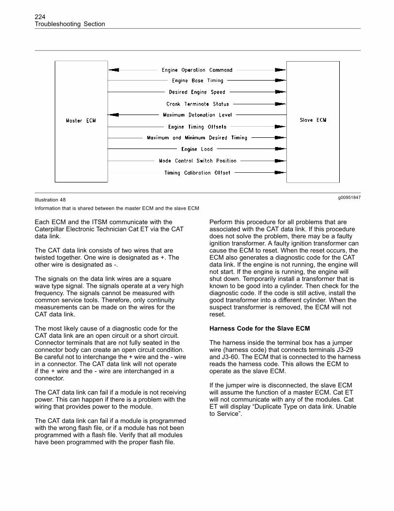
224Troubleshooting Section
g00951847Illustration 48
Information that is shared between the master ECM and the slave ECM
Each ECM and the ITSM communicate with theCaterpillar Electronic Technician Cat ET via the CATdata link.
The CAT data link consists of two wires that aretwisted together. One wire is designated as +. Theother wire is designated as -.
The signals on the data link wires are a squarewave type signal. The signals operate at a very highfrequency. The signals cannot be measured withcommon service tools. Therefore, only continuitymeasurements can be made on the wires for theCAT data link.
The most likely cause of a diagnostic code for theCAT data link are an open circuit or a short circuit.Connector terminals that are not fully seated in theconnector body can create an open circuit condition.Be careful not to interchange the + wire and the - wirein a connector. The CAT data link will not operateif the + wire and the - wire are interchanged in aconnector.
The CAT data link can fail if a module is not receivingpower. This can happen if there is a problem with thewiring that provides power to the module.
The CAT data link can fail if a module is programmedwith the wrong flash file, or if a module has not beenprogrammed with a flash file. Verify that all moduleshave been programmed with the proper flash file.
Perform this procedure for all problems that areassociated with the CAT data link. If this proceduredoes not solve the problem, there may be a faultyignition transformer. A faulty ignition transformer cancause the ECM to reset. When the reset occurs, theECM also generates a diagnostic code for the CATdata link. If the engine is not running, the engine willnot start. If the engine is running, the engine willshut down. Temporarily install a transformer that isknown to be good into a cylinder. Then check for thediagnostic code. If the code is still active, install thegood transformer into a different cylinder. When thesuspect transformer is removed, the ECM will notreset.
Harness Code for the Slave ECM
The harness inside the terminal box has a jumperwire (harness code) that connects terminals J3-29and J3-60. The ECM that is connected to the harnessreads the harness code. This allows the ECM tooperate as the slave ECM.
If the jumper wire is disconnected, the slave ECMwill assume the function of a master ECM. Cat ETwill not communicate with any of the modules. CatET will display “Duplicate Type on data link. Unableto Service”.
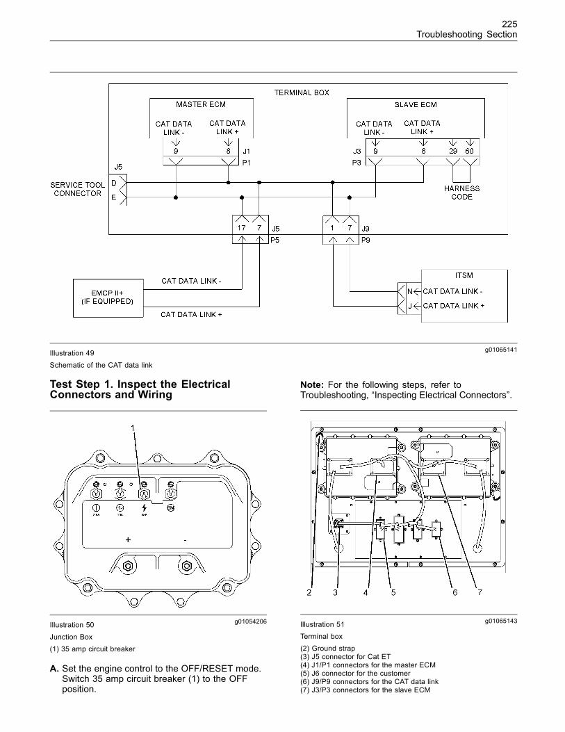
225Troubleshooting Section
g01065141Illustration 49
Schematic of the CAT data link
Test Step 1. Inspect the ElectricalConnectors and Wiring
g01054206Illustration 50
Junction Box(1) 35 amp circuit breaker
A. Set the engine control to the OFF/RESET mode.Switch 35 amp circuit breaker (1) to the OFFposition.
Note: For the following steps, refer toTroubleshooting, “Inspecting Electrical Connectors”.
g01065143Illustration 51Terminal box(2) Ground strap(3) J5 connector for Cat ET(4) J1/P1 connectors for the master ECM(5) J6 connector for the customer(6) J9/P9 connectors for the CAT data link(7) J3/P3 connectors for the slave ECM
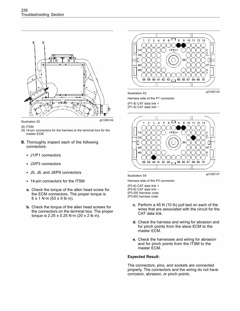
226Troubleshooting Section
g01065149Illustration 52
(8) ITSM(9) 14-pin connectors for the harness to the terminal box for the
master ECM
B. Thoroughly inspect each of the followingconnectors:
• J1/P1 connectors
• J3/P3 connectors
• J5, J6, and J9/P9 connectors
• 14-pin connectors for the ITSM
a. Check the torque of the allen head screw forthe ECM connectors. The proper torque is6 ± 1 N·m (53 ± 9 lb in).
b. Check the torque of the allen head screws forthe connectors on the terminal box. The propertorque is 2.25 ± 0.25 N·m (20 ± 2 lb in).
g01065145Illustration 53Harness side of the P1 connector
(P1-8) CAT data link +(P1-9) CAT data link −
g01065147Illustration 54Harness side of the P3 connector(P3-8) CAT data link +(P3-9) CAT data link −(P3-29) Harness code(P3-60) harness code
c. Perform a 45 N (10 lb) pull test on each of thewires that are associated with the circuit for theCAT data link.
d. Check the harness and wiring for abrasion andfor pinch points from the slave ECM to themaster ECM.
e. Check the harnesses and wiring for abrasionand for pinch points from the ITSM to themaster ECM.
Expected Result:
The connectors, pins, and sockets are connectedproperly. The connectors and the wiring do not havecorrosion, abrasion, or pinch points.
227Troubleshooting Section
Results:
• OK – The components are in good condition withproper connections. Proceed to Test Step 2.
• Not OK – The components are not in goodcondition and/or at least one connection isimproper.
Repair: Perform the necessary repairs and/orreplace parts, if necessary.
STOP.
Test Step 2. Check the CAT Data Link
A. Verify that the engine control is in the OFF/RESETmode. Verify that the 35 amp circuit breaker isOFF.
B. Connect Cat ET to the service tool connector.Refer to Troubleshooting, “Electronic ServiceTools”.
C. Set the engine control to the STOP mode. Switchthe 35 amp circuit breaker ON.
D. Select the “File/Select ECM” menu on the Cat ET.Verify that all of the modules are displayed on the“ECM Selector” screen.
Verify that the following diagnostic codes are notactivated.
• 0590-09 Unable to communicate with EngineECM
• 1636-09 Loss of communication with Engine#2 (Slave)
• 1042-09 Unable to communicate with ITSM
Note: If Cat ET displays “Duplicate Type on datalink. Unable to Service”, there may be a problem withthe harness inside the terminal box. Set the enginecontrol to the OFF/RESET mode. Switch the 35 ampcircuit breaker OFF. Check the continuity betweenterminals J3-29 and J3-60. Verify that the jumper wireis in good condition. Make repairs, as needed.
Expected Result:
All of the modules are displayed on the “ECMSelector” screen. There are no active diagnosticcodes for the CAT data link.
Results:
• OK – All of the modules are displayed on the “ECMSelector” screen. There are no active diagnosticcodes for the CAT data link. The problem seemsto be resolved.
Repair: If any of the above codes are loggedand the engine is not running properly, refer toTroubleshooting, “Troubleshooting Without aDiagnostic Code”.
If any of the above codes are logged and theengine is running properly, there may be anintermittent problem in a connector or a wiringharness. Refer to Troubleshooting, “InspectingElectrical Connectors”.
STOP.
• Not OK – At least one of the modules is notdisplayed on the “ECM Selector” screen. Theremay be an active diagnostic code for the CAT datalink. Proceed to Test Step 3.
Test Step 3. Check the Wiring for the CATData Link
A. Set the engine control to the OFF/RESET mode.Switch the 35 amp circuit breaker OFF.
B. Disconnect Cat ET from the service tool connector.
C. Disconnect the following connectors:
• P1 connector from the master ECM
• P3 connector from the slave ECM
• P6 connector (if equipped)
• 14-pin connector from the ITSM
D. Measure the resistance between the points thatare listed in Table 15. During each measurement,wiggle the wires in the harness in order to checkfor an intermittent problem. Be sure to wiggle thewires near each of the connectors.
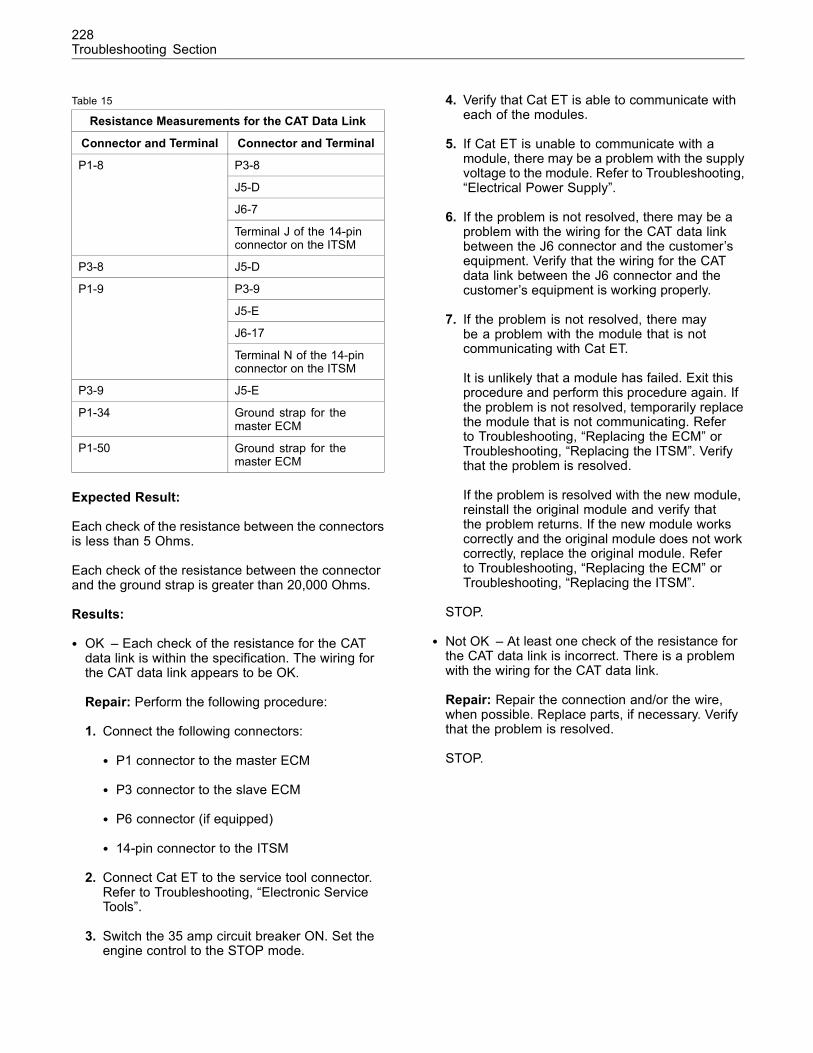
228Troubleshooting Section
Table 15
Resistance Measurements for the CAT Data Link
Connector and Terminal Connector and Terminal
P3-8
J5-D
J6-7
P1-8
Terminal J of the 14-pinconnector on the ITSM
P3-8 J5-D
P3-9
J5-E
J6-17
P1-9
Terminal N of the 14-pinconnector on the ITSM
P3-9 J5-E
P1-34 Ground strap for themaster ECM
P1-50 Ground strap for themaster ECM
Expected Result:
Each check of the resistance between the connectorsis less than 5 Ohms.
Each check of the resistance between the connectorand the ground strap is greater than 20,000 Ohms.
Results:
• OK – Each check of the resistance for the CATdata link is within the specification. The wiring forthe CAT data link appears to be OK.
Repair: Perform the following procedure:
1. Connect the following connectors:
• P1 connector to the master ECM
• P3 connector to the slave ECM
• P6 connector (if equipped)
• 14-pin connector to the ITSM
2. Connect Cat ET to the service tool connector.Refer to Troubleshooting, “Electronic ServiceTools”.
3. Switch the 35 amp circuit breaker ON. Set theengine control to the STOP mode.
4. Verify that Cat ET is able to communicate witheach of the modules.
5. If Cat ET is unable to communicate with amodule, there may be a problem with the supplyvoltage to the module. Refer to Troubleshooting,“Electrical Power Supply”.
6. If the problem is not resolved, there may be aproblem with the wiring for the CAT data linkbetween the J6 connector and the customer’sequipment. Verify that the wiring for the CATdata link between the J6 connector and thecustomer’s equipment is working properly.
7. If the problem is not resolved, there maybe a problem with the module that is notcommunicating with Cat ET.
It is unlikely that a module has failed. Exit thisprocedure and perform this procedure again. Ifthe problem is not resolved, temporarily replacethe module that is not communicating. Referto Troubleshooting, “Replacing the ECM” orTroubleshooting, “Replacing the ITSM”. Verifythat the problem is resolved.
If the problem is resolved with the new module,reinstall the original module and verify thatthe problem returns. If the new module workscorrectly and the original module does not workcorrectly, replace the original module. Referto Troubleshooting, “Replacing the ECM” orTroubleshooting, “Replacing the ITSM”.
STOP.
• Not OK – At least one check of the resistance forthe CAT data link is incorrect. There is a problemwith the wiring for the CAT data link.
Repair: Repair the connection and/or the wire,when possible. Replace parts, if necessary. Verifythat the problem is resolved.
STOP.
229Troubleshooting Section
i02088898
Compressor BypassSMCS Code: 1052-038-BV
System Operation Description:
A bypass valve is connected between the outletsfor the turbocharger compressors and the inlets forthe turbocharger compressors. The bypass valveis activated by an actuator. The master ElectronicControl Module (ECM) activates the actuator for thebypass valve during these conditions:
• Turbocharger surge
• Engine shutdown
Turbocharger Surge
A rapid drop in the output power of the generatorcan cause the engine’s speed to quickly increase.The increased speed of the engine causes theturbochargers to overspeed temporarily. This iscalled a turbocharger surge. Surging can damagethe turbochargers.
The master ECM continuously monitors the speedof the engine. The master ECM responds to a rapidincrease in the speed of the engine by activating theactuator for the bypass valve. The actuator opensthe valve.
The valve allows the compressed air/fuel mixture inthe aftercooler’s inlet to flow into the intake of theturbocharger’s compressor. This reduces the boostpressure in the air inlet manifold.
Engine Shutdown
Engine shutdown occurs when the output for thefuel control relay is OFF and the engine RPM isabove 100. The master ECM activates the actuatorfor the bypass valve until the engine RPM drops tozero. This scavenges any unburned gases in thecomponents of the system during engine shutdown.
CAN Data Link
The master ECM and the actuator communicatevia the CAN data link. The master ECM sends acommand signal to the actuator. The actuator sendsthe following information to the master ECM: actuatorposition, CCM heartbeat, software version, andinternal fault diagnosis.
If the master ECM cannot communicate with theactuator, the master ECM activates a 1720-09diagnostic code and the engine is shut down. A1720-09 diagnostic code is probably caused by aproblem with an electrical connector or a harness.The next likely cause is a problem with the actuator.The least likely cause is a problem with the masterECM.
Terminating resistors must be connected to eachend of the CAN data link. The terminating resistorsimprove the communication between the devices. Ifthere is an intermittent diagnostic code for any of thedevices that are connected to the CAN data link, besure to check the terminating resistor that is insidethe terminal box. Also check the jumper wire that isconnected between terminals J and K on the actuatorfor the bypass valve. Make repairs, when possible.Replace parts, if necessary.
Identification on the CAN Data Link
When the actuator for the bypass valve is poweredup, the actuator looks for a ground on terminal N. Ifthere is a ground on terminal N, the actuator will havea unique identification on the CAN data link.
If there is no ground on terminal N and the actuatoris powered up, the actuator for the bypass valve andthe throttle actuator will have the same identification.The master ECM will not communicate with theactuator for the bypass valve. Instead, the masterECM will activate a 1720-09 diagnostic code. Theengine will not start.
The electrical connector for the actuator is designedso that the terminals for electrical power areconnected before terminal N. For this reason,electrical power must be removed before theconnector for the actuator is connected.
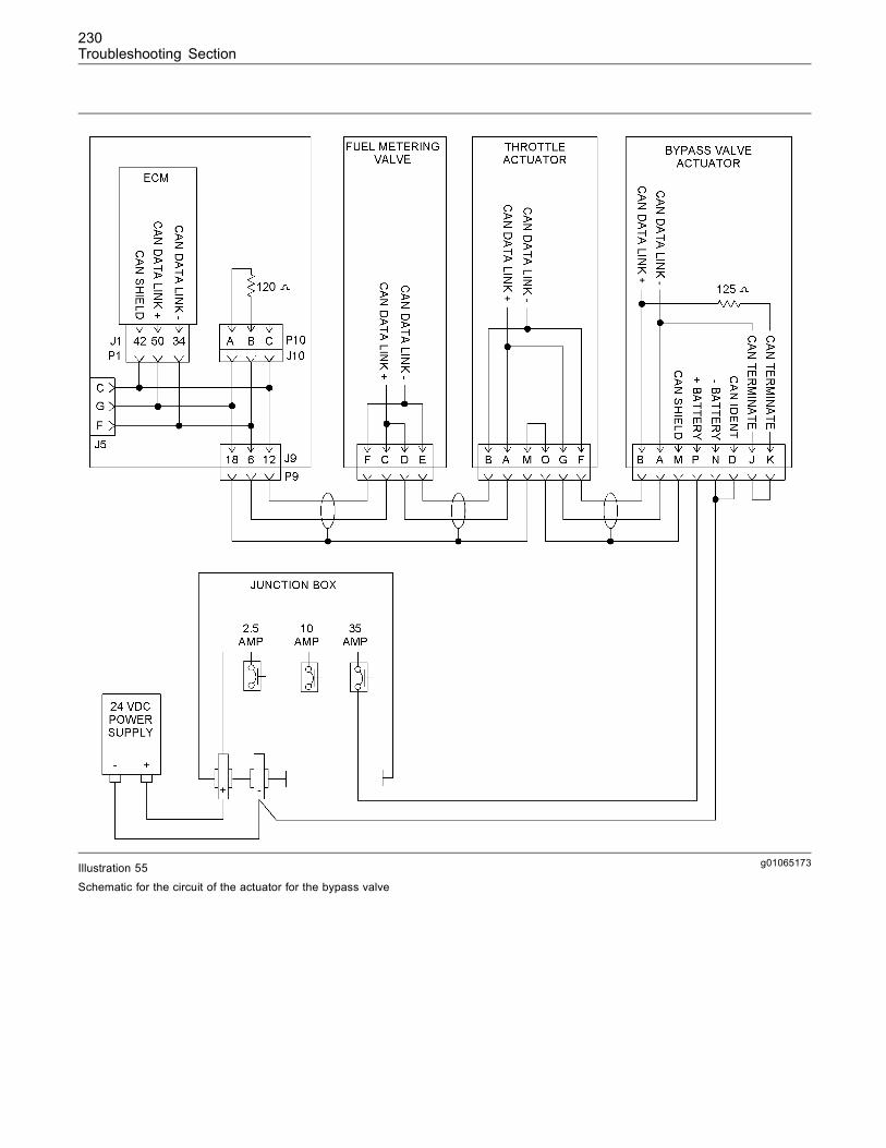
230Troubleshooting Section
g01065173Illustration 55
Schematic for the circuit of the actuator for the bypass valve
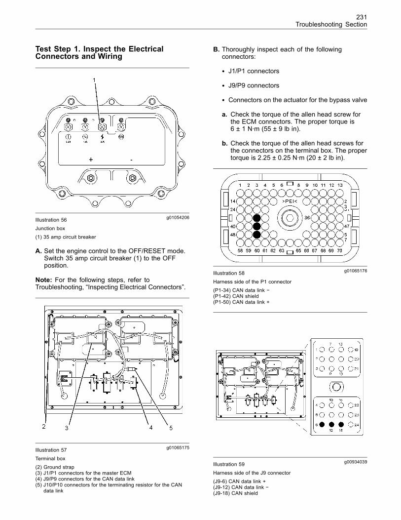
231Troubleshooting Section
Test Step 1. Inspect the ElectricalConnectors and Wiring
g01054206Illustration 56Junction box
(1) 35 amp circuit breaker
A. Set the engine control to the OFF/RESET mode.Switch 35 amp circuit breaker (1) to the OFFposition.
Note: For the following steps, refer toTroubleshooting, “Inspecting Electrical Connectors”.
g01065175Illustration 57
Terminal box
(2) Ground strap(3) J1/P1 connectors for the master ECM(4) J9/P9 connectors for the CAN data link(5) J10/P10 connectors for the terminating resistor for the CAN
data link
B. Thoroughly inspect each of the followingconnectors:
• J1/P1 connectors
• J9/P9 connectors
• Connectors on the actuator for the bypass valve
a. Check the torque of the allen head screw forthe ECM connectors. The proper torque is6 ± 1 N·m (55 ± 9 lb in).
b. Check the torque of the allen head screws forthe connectors on the terminal box. The propertorque is 2.25 ± 0.25 N·m (20 ± 2 lb in).
g01065176Illustration 58
Harness side of the P1 connector(P1-34) CAN data link −(P1-42) CAN shield(P1-50) CAN data link +
g00934039Illustration 59
Harness side of the J9 connector(J9-6) CAN data link +(J9-12) CAN data link −(J9-18) CAN shield
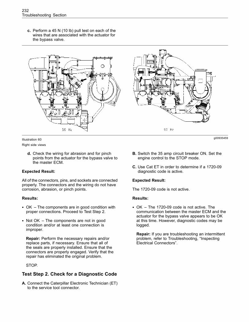
232Troubleshooting Section
c. Perform a 45 N (10 lb) pull test on each of thewires that are associated with the actuator forthe bypass valve.
g00935459Illustration 60
Right side views
d. Check the wiring for abrasion and for pinchpoints from the actuator for the bypass valve tothe master ECM.
Expected Result:
All of the connectors, pins, and sockets are connectedproperly. The connectors and the wiring do not havecorrosion, abrasion, or pinch points.
Results:
• OK – The components are in good condition withproper connections. Proceed to Test Step 2.
• Not OK – The components are not in goodcondition and/or at least one connection isimproper.
Repair: Perform the necessary repairs and/orreplace parts, if necessary. Ensure that all ofthe seals are properly installed. Ensure that theconnectors are properly engaged. Verify that therepair has eliminated the original problem.
STOP.
Test Step 2. Check for a Diagnostic Code
A. Connect the Caterpillar Electronic Technician (ET)to the service tool connector.
B. Switch the 35 amp circuit breaker ON. Set theengine control to the STOP mode.
C. Use Cat ET in order to determine if a 1720-09diagnostic code is active.
Expected Result:
The 1720-09 code is not active.
Results:
• OK – The 1720-09 code is not active. Thecommunication between the master ECM and theactuator for the bypass valve appears to be OKat this time. However, diagnostic codes may belogged.
Repair: If you are troubleshooting an intermittentproblem, refer to Troubleshooting, “InspectingElectrical Connectors”.
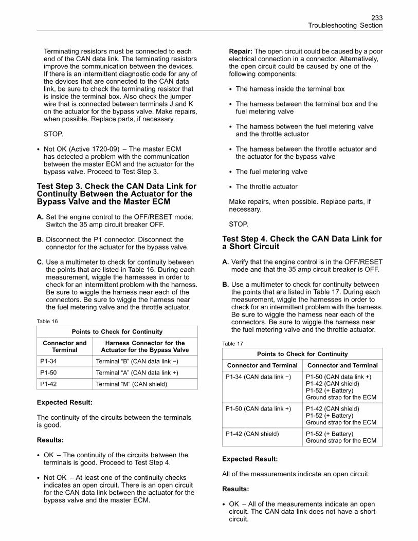
233Troubleshooting Section
Terminating resistors must be connected to eachend of the CAN data link. The terminating resistorsimprove the communication between the devices.If there is an intermittent diagnostic code for any ofthe devices that are connected to the CAN datalink, be sure to check the terminating resistor thatis inside the terminal box. Also check the jumperwire that is connected between terminals J and Kon the actuator for the bypass valve. Make repairs,when possible. Replace parts, if necessary.
STOP.
• Not OK (Active 1720-09) – The master ECMhas detected a problem with the communicationbetween the master ECM and the actuator for thebypass valve. Proceed to Test Step 3.
Test Step 3. Check the CAN Data Link forContinuity Between the Actuator for theBypass Valve and the Master ECM
A. Set the engine control to the OFF/RESET mode.Switch the 35 amp circuit breaker OFF.
B. Disconnect the P1 connector. Disconnect theconnector for the actuator for the bypass valve.
C. Use a multimeter to check for continuity betweenthe points that are listed in Table 16. During eachmeasurement, wiggle the harnesses in order tocheck for an intermittent problem with the harness.Be sure to wiggle the harness near each of theconnectors. Be sure to wiggle the harness nearthe fuel metering valve and the throttle actuator.
Table 16
Points to Check for Continuity
Connector andTerminal
Harness Connector for theActuator for the Bypass Valve
P1-34 Terminal “B” (CAN data link −)
P1-50 Terminal “A” (CAN data link +)
P1-42 Terminal “M” (CAN shield)
Expected Result:
The continuity of the circuits between the terminalsis good.
Results:
• OK – The continuity of the circuits between theterminals is good. Proceed to Test Step 4.
• Not OK – At least one of the continuity checksindicates an open circuit. There is an open circuitfor the CAN data link between the actuator for thebypass valve and the master ECM.
Repair: The open circuit could be caused by a poorelectrical connection in a connector. Alternatively,the open circuit could be caused by one of thefollowing components:
• The harness inside the terminal box
• The harness between the terminal box and thefuel metering valve
• The harness between the fuel metering valveand the throttle actuator
• The harness between the throttle actuator andthe actuator for the bypass valve
• The fuel metering valve
• The throttle actuator
Make repairs, when possible. Replace parts, ifnecessary.
STOP.
Test Step 4. Check the CAN Data Link fora Short Circuit
A. Verify that the engine control is in the OFF/RESETmode and that the 35 amp circuit breaker is OFF.
B. Use a multimeter to check for continuity betweenthe points that are listed in Table 17. During eachmeasurement, wiggle the harnesses in order tocheck for an intermittent problem with the harness.Be sure to wiggle the harness near each of theconnectors. Be sure to wiggle the harness nearthe fuel metering valve and the throttle actuator.
Table 17
Points to Check for Continuity
Connector and Terminal Connector and Terminal
P1-34 (CAN data link −) P1-50 (CAN data link +)P1-42 (CAN shield)P1-52 (+ Battery)Ground strap for the ECM
P1-50 (CAN data link +) P1-42 (CAN shield)P1-52 (+ Battery)Ground strap for the ECM
P1-42 (CAN shield) P1-52 (+ Battery)Ground strap for the ECM
Expected Result:
All of the measurements indicate an open circuit.
Results:
• OK – All of the measurements indicate an opencircuit. The CAN data link does not have a shortcircuit.
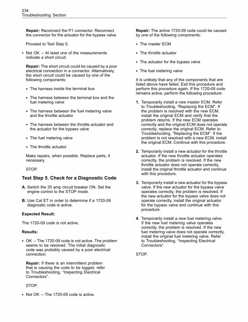
234Troubleshooting Section
Repair: Reconnect the P1 connector. Reconnectthe connector for the actuator for the bypass valve.
Proceed to Test Step 5.
• Not OK – At least one of the measurementsindicate a short circuit.
Repair: The short circuit could be caused by a poorelectrical connection in a connector. Alternatively,the short circuit could be caused by one of thefollowing components:
• The harness inside the terminal box
• The harness between the terminal box and thefuel metering valve
• The harness between the fuel metering valveand the throttle actuator
• The harness between the throttle actuator andthe actuator for the bypass valve
• The fuel metering valve
• The throttle actuator
Make repairs, when possible. Replace parts, ifnecessary.
STOP.
Test Step 5. Check for a Diagnostic Code
A. Switch the 35 amp circuit breaker ON. Set theengine control to the STOP mode.
B. Use Cat ET in order to determine if a 1720-09diagnostic code is active.
Expected Result:
The 1720-09 code is not active.
Results:
• OK – The 1720-09 code is not active. The problemseems to be resolved. The initial diagnosticcode was probably caused by a poor electricalconnection.
Repair: If there is an intermittent problemthat is causing the code to be logged, referto Troubleshooting, “Inspecting ElectricalConnectors”.
STOP.
• Not OK – The 1720-09 code is active.
Repair: The active 1720-09 code could be causedby one of the following components:
• The master ECM
• The throttle actuator
• The actuator for the bypass valve
• The fuel metering valve
It is unlikely that any of the components that arelisted above have failed. Exit this procedure andperform this procedure again. If the 1720-09 coderemains active, perform the following procedure:
1. Temporarily install a new master ECM. Referto Troubleshooting, “Replacing the ECM”. Ifthe problem is resolved with the new ECM,install the original ECM and verify that theproblem returns. If the new ECM operatescorrectly and the original ECM does not operatecorrectly, replace the original ECM. Refer toTroubleshooting, “Replacing the ECM”. If theproblem is not resolved with a new ECM, installthe original ECM. Continue with this procedure.
2. Temporarily install a new actuator for the throttleactuator. If the new throttle actuator operatescorrectly, the problem is resolved. If the newthrottle actuator does not operate correctly,install the original throttle actuator and continuewith this procedure.
3. Temporarily install a new actuator for the bypassvalve. If the new actuator for the bypass valveoperates correctly, the problem is resolved. Ifthe new actuator for the bypass valve does notoperate correctly, install the original actuatorfor the bypass valve and continue with thisprocedure.
4. Temporarily install a new fuel metering valve.If the new fuel metering valve operatescorrectly, the problem is resolved. If the newfuel metering valve does not operate correctly,install the original fuel metering valve. Referto Troubleshooting, “Inspecting ElectricalConnectors”.
STOP.
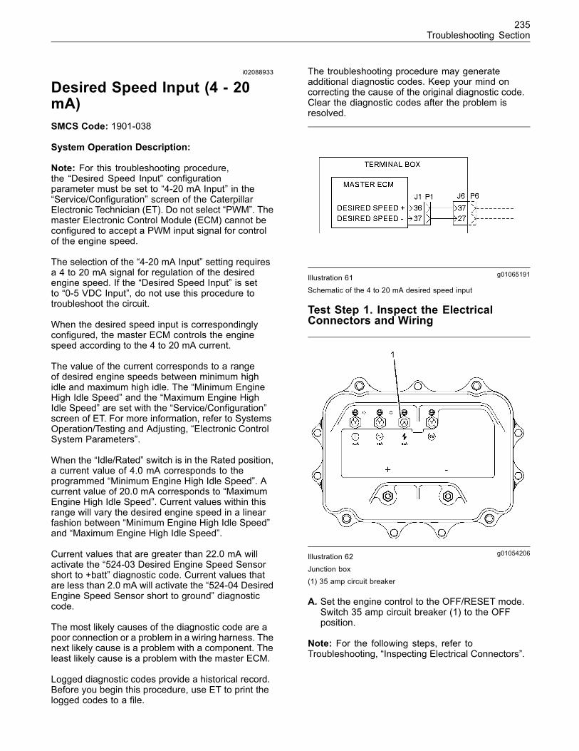
235Troubleshooting Section
i02088933
Desired Speed Input (4 - 20mA)SMCS Code: 1901-038
System Operation Description:
Note: For this troubleshooting procedure,the “Desired Speed Input” configurationparameter must be set to “4-20 mA Input” in the“Service/Configuration” screen of the CaterpillarElectronic Technician (ET). Do not select “PWM”. Themaster Electronic Control Module (ECM) cannot beconfigured to accept a PWM input signal for controlof the engine speed.
The selection of the “4-20 mA Input” setting requiresa 4 to 20 mA signal for regulation of the desiredengine speed. If the “Desired Speed Input” is setto “0-5 VDC Input”, do not use this procedure totroubleshoot the circuit.
When the desired speed input is correspondinglyconfigured, the master ECM controls the enginespeed according to the 4 to 20 mA current.
The value of the current corresponds to a rangeof desired engine speeds between minimum highidle and maximum high idle. The “Minimum EngineHigh Idle Speed” and the “Maximum Engine HighIdle Speed” are set with the “Service/Configuration”screen of ET. For more information, refer to SystemsOperation/Testing and Adjusting, “Electronic ControlSystem Parameters”.
When the “Idle/Rated” switch is in the Rated position,a current value of 4.0 mA corresponds to theprogrammed “Minimum Engine High Idle Speed”. Acurrent value of 20.0 mA corresponds to “MaximumEngine High Idle Speed”. Current values within thisrange will vary the desired engine speed in a linearfashion between “Minimum Engine High Idle Speed”and “Maximum Engine High Idle Speed”.
Current values that are greater than 22.0 mA willactivate the “524-03 Desired Engine Speed Sensorshort to +batt” diagnostic code. Current values thatare less than 2.0 mA will activate the “524-04 DesiredEngine Speed Sensor short to ground” diagnosticcode.
The most likely causes of the diagnostic code are apoor connection or a problem in a wiring harness. Thenext likely cause is a problem with a component. Theleast likely cause is a problem with the master ECM.
Logged diagnostic codes provide a historical record.Before you begin this procedure, use ET to print thelogged codes to a file.
The troubleshooting procedure may generateadditional diagnostic codes. Keep your mind oncorrecting the cause of the original diagnostic code.Clear the diagnostic codes after the problem isresolved.
g01065191Illustration 61
Schematic of the 4 to 20 mA desired speed input
Test Step 1. Inspect the ElectricalConnectors and Wiring
g01054206Illustration 62
Junction box(1) 35 amp circuit breaker
A. Set the engine control to the OFF/RESET mode.Switch 35 amp circuit breaker (1) to the OFFposition.
Note: For the following steps, refer toTroubleshooting, “Inspecting Electrical Connectors”.
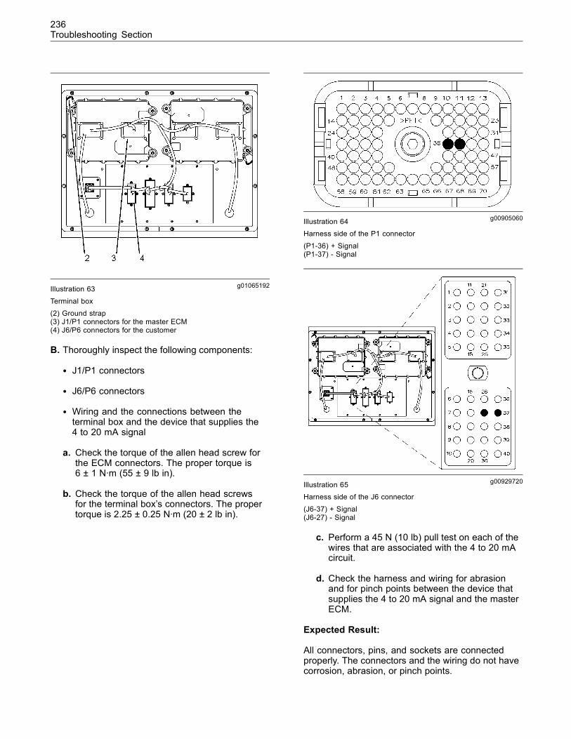
236Troubleshooting Section
g01065192Illustration 63
Terminal box(2) Ground strap(3) J1/P1 connectors for the master ECM(4) J6/P6 connectors for the customer
B. Thoroughly inspect the following components:
• J1/P1 connectors
• J6/P6 connectors
• Wiring and the connections between theterminal box and the device that supplies the4 to 20 mA signal
a. Check the torque of the allen head screw forthe ECM connectors. The proper torque is6 ± 1 N·m (55 ± 9 lb in).
b. Check the torque of the allen head screwsfor the terminal box’s connectors. The propertorque is 2.25 ± 0.25 N·m (20 ± 2 lb in).
g00905060Illustration 64Harness side of the P1 connector
(P1-36) + Signal(P1-37) - Signal
g00929720Illustration 65Harness side of the J6 connector
(J6-37) + Signal(J6-27) - Signal
c. Perform a 45 N (10 lb) pull test on each of thewires that are associated with the 4 to 20 mAcircuit.
d. Check the harness and wiring for abrasionand for pinch points between the device thatsupplies the 4 to 20 mA signal and the masterECM.
Expected Result:
All connectors, pins, and sockets are connectedproperly. The connectors and the wiring do not havecorrosion, abrasion, or pinch points.
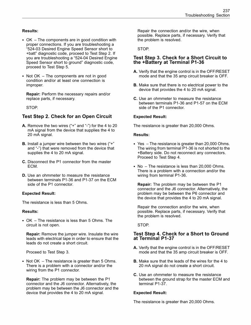
237Troubleshooting Section
Results:
• OK – The components are in good condition withproper connections. If you are troubleshooting a“524-03 Desired Engine Speed Sensor short to+batt” diagnostic code, proceed to Test Step 2. Ifyou are troubleshooting a “524-04 Desired EngineSpeed Sensor short to ground” diagnostic code,proceed to Test Step 5.
• Not OK – The components are not in goodcondition and/or at least one connection isimproper.
Repair: Perform the necessary repairs and/orreplace parts, if necessary.
STOP.
Test Step 2. Check for an Open Circuit
A. Remove the two wires (“+” and “-”) for the 4 to 20mA signal from the device that supplies the 4 to20 mA signal.
B. Install a jumper wire between the two wires (“+”and “-”) that were removed from the device thatsupplies the 4 to 20 mA signal.
C. Disconnect the P1 connector from the masterECM.
D. Use an ohmmeter to measure the resistancebetween terminals P1-36 and P1-37 on the ECMside of the P1 connector.
Expected Result:
The resistance is less than 5 Ohms.
Results:
• OK – The resistance is less than 5 Ohms. Thecircuit is not open.
Repair: Remove the jumper wire. Insulate the wireleads with electrical tape in order to ensure that theleads do not create a short circuit.
Proceed to Test Step 3.
• Not OK – The resistance is greater than 5 Ohms.There is a problem with a connector and/or thewiring from the P1 connector.
Repair: The problem may be between the P1connector and the J6 connector. Alternatively, theproblem may be between the J6 connector and thedevice that provides the 4 to 20 mA signal.
Repair the connection and/or the wire, whenpossible. Replace parts, if necessary. Verify thatthe problem is resolved.
STOP.
Test Step 3. Check for a Short Circuit tothe +Battery at Terminal P1-36
A. Verify that the engine control is in the OFF/RESETmode and that the 35 amp circuit breaker is OFF.
B. Make sure that there is no electrical power to thedevice that provides the 4 to 20 mA signal.
C. Use an ohmmeter to measure the resistancebetween terminals P1-36 and P1-57 on the ECMside of the P1 connector.
Expected Result:
The resistance is greater than 20,000 Ohms.
Results:
• Yes – The resistance is greater than 20,000 Ohms.The wiring from terminal P1-36 is not shorted to the+Battery side. Do not reconnect any connectors.Proceed to Test Step 4.
• No – The resistance is less than 20,000 Ohms.There is a problem with a connection and/or thewiring from terminal P1-36.
Repair: The problem may be between the P1connector and the J6 connector. Alternatively, theproblem may be between the P6 connector andthe device that provides the 4 to 20 mA signal.
Repair the connection and/or the wire, whenpossible. Replace parts, if necessary. Verify thatthe problem is resolved.
STOP.
Test Step 4. Check for a Short to Groundat Terminal P1-37
A. Verify that the engine control is in the OFF/RESETmode and that the 35 amp circuit breaker is OFF.
B. Make sure that the leads of the wires for the 4 to20 mA signal do not create a short circuit.
C. Use an ohmmeter to measure the resistancebetween the ground strap for the master ECM andterminal P1-37.
Expected Result:
The resistance is greater than 20,000 Ohms.
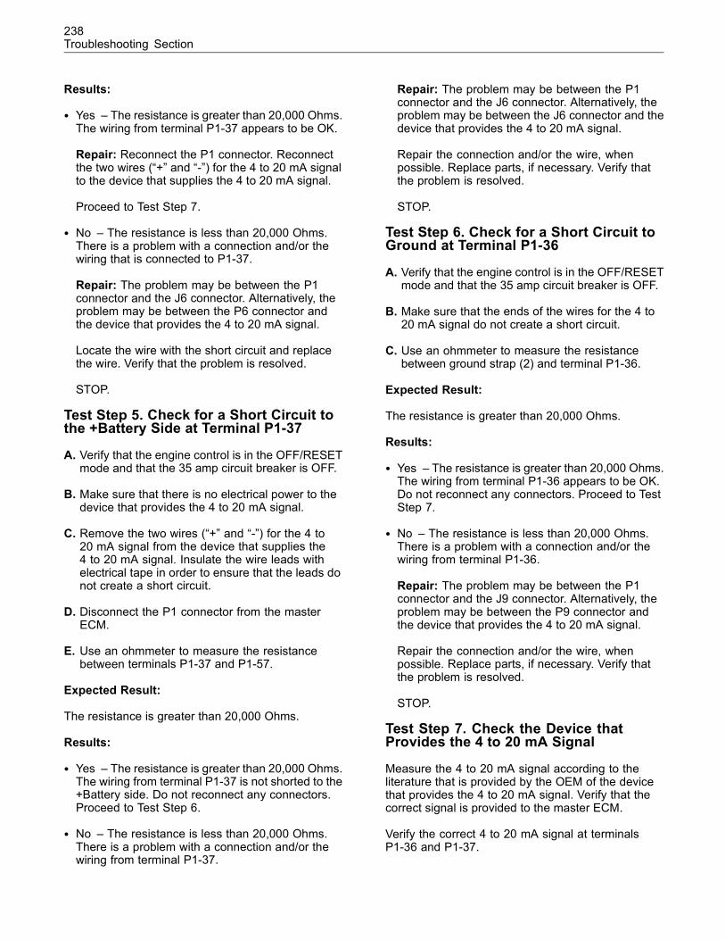
238Troubleshooting Section
Results:
• Yes – The resistance is greater than 20,000 Ohms.The wiring from terminal P1-37 appears to be OK.
Repair: Reconnect the P1 connector. Reconnectthe two wires (“+” and “-”) for the 4 to 20 mA signalto the device that supplies the 4 to 20 mA signal.
Proceed to Test Step 7.
• No – The resistance is less than 20,000 Ohms.There is a problem with a connection and/or thewiring that is connected to P1-37.
Repair: The problem may be between the P1connector and the J6 connector. Alternatively, theproblem may be between the P6 connector andthe device that provides the 4 to 20 mA signal.
Locate the wire with the short circuit and replacethe wire. Verify that the problem is resolved.
STOP.
Test Step 5. Check for a Short Circuit tothe +Battery Side at Terminal P1-37
A. Verify that the engine control is in the OFF/RESETmode and that the 35 amp circuit breaker is OFF.
B. Make sure that there is no electrical power to thedevice that provides the 4 to 20 mA signal.
C. Remove the two wires (“+” and “-”) for the 4 to20 mA signal from the device that supplies the4 to 20 mA signal. Insulate the wire leads withelectrical tape in order to ensure that the leads donot create a short circuit.
D. Disconnect the P1 connector from the masterECM.
E. Use an ohmmeter to measure the resistancebetween terminals P1-37 and P1-57.
Expected Result:
The resistance is greater than 20,000 Ohms.
Results:
• Yes – The resistance is greater than 20,000 Ohms.The wiring from terminal P1-37 is not shorted to the+Battery side. Do not reconnect any connectors.Proceed to Test Step 6.
• No – The resistance is less than 20,000 Ohms.There is a problem with a connection and/or thewiring from terminal P1-37.
Repair: The problem may be between the P1connector and the J6 connector. Alternatively, theproblem may be between the J6 connector and thedevice that provides the 4 to 20 mA signal.
Repair the connection and/or the wire, whenpossible. Replace parts, if necessary. Verify thatthe problem is resolved.
STOP.
Test Step 6. Check for a Short Circuit toGround at Terminal P1-36
A. Verify that the engine control is in the OFF/RESETmode and that the 35 amp circuit breaker is OFF.
B. Make sure that the ends of the wires for the 4 to20 mA signal do not create a short circuit.
C. Use an ohmmeter to measure the resistancebetween ground strap (2) and terminal P1-36.
Expected Result:
The resistance is greater than 20,000 Ohms.
Results:
• Yes – The resistance is greater than 20,000 Ohms.The wiring from terminal P1-36 appears to be OK.Do not reconnect any connectors. Proceed to TestStep 7.
• No – The resistance is less than 20,000 Ohms.There is a problem with a connection and/or thewiring from terminal P1-36.
Repair: The problem may be between the P1connector and the J9 connector. Alternatively, theproblem may be between the P9 connector andthe device that provides the 4 to 20 mA signal.
Repair the connection and/or the wire, whenpossible. Replace parts, if necessary. Verify thatthe problem is resolved.
STOP.
Test Step 7. Check the Device thatProvides the 4 to 20 mA Signal
Measure the 4 to 20 mA signal according to theliterature that is provided by the OEM of the devicethat provides the 4 to 20 mA signal. Verify that thecorrect signal is provided to the master ECM.
Verify the correct 4 to 20 mA signal at terminalsP1-36 and P1-37.
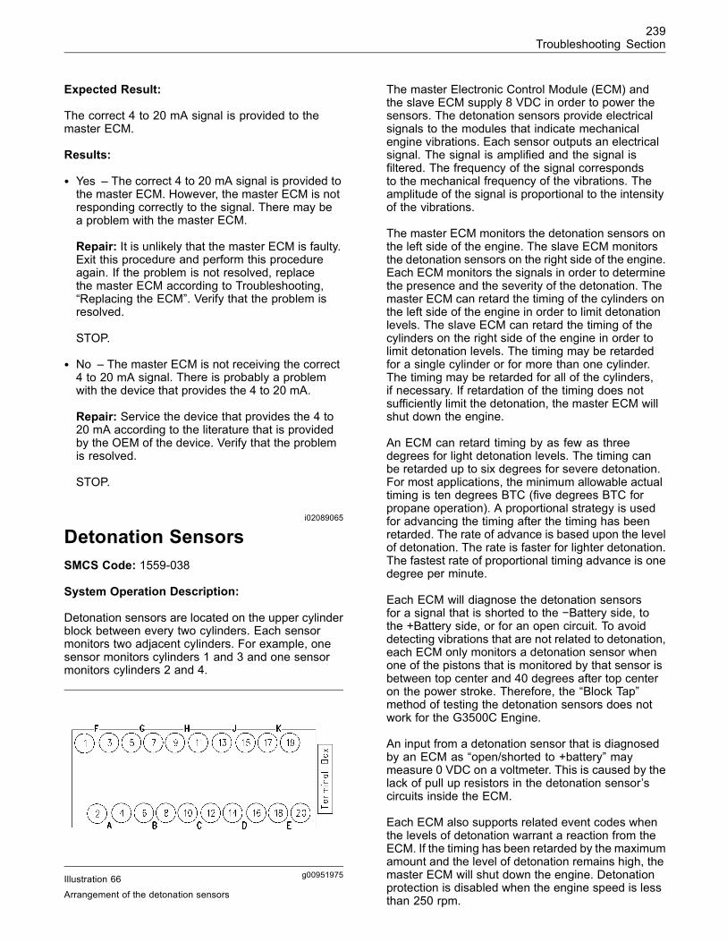
239Troubleshooting Section
Expected Result:
The correct 4 to 20 mA signal is provided to themaster ECM.
Results:
• Yes – The correct 4 to 20 mA signal is provided tothe master ECM. However, the master ECM is notresponding correctly to the signal. There may bea problem with the master ECM.
Repair: It is unlikely that the master ECM is faulty.Exit this procedure and perform this procedureagain. If the problem is not resolved, replacethe master ECM according to Troubleshooting,“Replacing the ECM”. Verify that the problem isresolved.
STOP.
• No – The master ECM is not receiving the correct4 to 20 mA signal. There is probably a problemwith the device that provides the 4 to 20 mA.
Repair: Service the device that provides the 4 to20 mA according to the literature that is providedby the OEM of the device. Verify that the problemis resolved.
STOP.
i02089065
Detonation SensorsSMCS Code: 1559-038
System Operation Description:
Detonation sensors are located on the upper cylinderblock between every two cylinders. Each sensormonitors two adjacent cylinders. For example, onesensor monitors cylinders 1 and 3 and one sensormonitors cylinders 2 and 4.
g00951975Illustration 66Arrangement of the detonation sensors
The master Electronic Control Module (ECM) andthe slave ECM supply 8 VDC in order to power thesensors. The detonation sensors provide electricalsignals to the modules that indicate mechanicalengine vibrations. Each sensor outputs an electricalsignal. The signal is amplified and the signal isfiltered. The frequency of the signal correspondsto the mechanical frequency of the vibrations. Theamplitude of the signal is proportional to the intensityof the vibrations.
The master ECM monitors the detonation sensors onthe left side of the engine. The slave ECM monitorsthe detonation sensors on the right side of the engine.Each ECM monitors the signals in order to determinethe presence and the severity of the detonation. Themaster ECM can retard the timing of the cylinders onthe left side of the engine in order to limit detonationlevels. The slave ECM can retard the timing of thecylinders on the right side of the engine in order tolimit detonation levels. The timing may be retardedfor a single cylinder or for more than one cylinder.The timing may be retarded for all of the cylinders,if necessary. If retardation of the timing does notsufficiently limit the detonation, the master ECM willshut down the engine.
An ECM can retard timing by as few as threedegrees for light detonation levels. The timing canbe retarded up to six degrees for severe detonation.For most applications, the minimum allowable actualtiming is ten degrees BTC (five degrees BTC forpropane operation). A proportional strategy is usedfor advancing the timing after the timing has beenretarded. The rate of advance is based upon the levelof detonation. The rate is faster for lighter detonation.The fastest rate of proportional timing advance is onedegree per minute.
Each ECM will diagnose the detonation sensorsfor a signal that is shorted to the −Battery side, tothe +Battery side, or for an open circuit. To avoiddetecting vibrations that are not related to detonation,each ECM only monitors a detonation sensor whenone of the pistons that is monitored by that sensor isbetween top center and 40 degrees after top centeron the power stroke. Therefore, the “Block Tap”method of testing the detonation sensors does notwork for the G3500C Engine.
An input from a detonation sensor that is diagnosedby an ECM as “open/shorted to +battery” maymeasure 0 VDC on a voltmeter. This is caused by thelack of pull up resistors in the detonation sensor’scircuits inside the ECM.
Each ECM also supports related event codes whenthe levels of detonation warrant a reaction from theECM. If the timing has been retarded by the maximumamount and the level of detonation remains high, themaster ECM will shut down the engine. Detonationprotection is disabled when the engine speed is lessthan 250 rpm.
240Troubleshooting Section
Logged diagnostic codes provide a historical record.Before you begin this procedure, use the CaterpillarElectronic Technician (ET) to print the logged codesto a file.
The most likely causes of the diagnostic code are apoor connection or a problem in a wiring harness.The next likely cause is a problem with a sensor. Theleast likely cause is a problem with an ECM.
The troubleshooting procedure may generateadditional diagnostic codes. Keep your mind oncorrecting the cause of the original diagnostic code.Clear the diagnostic codes after the problem isresolved.
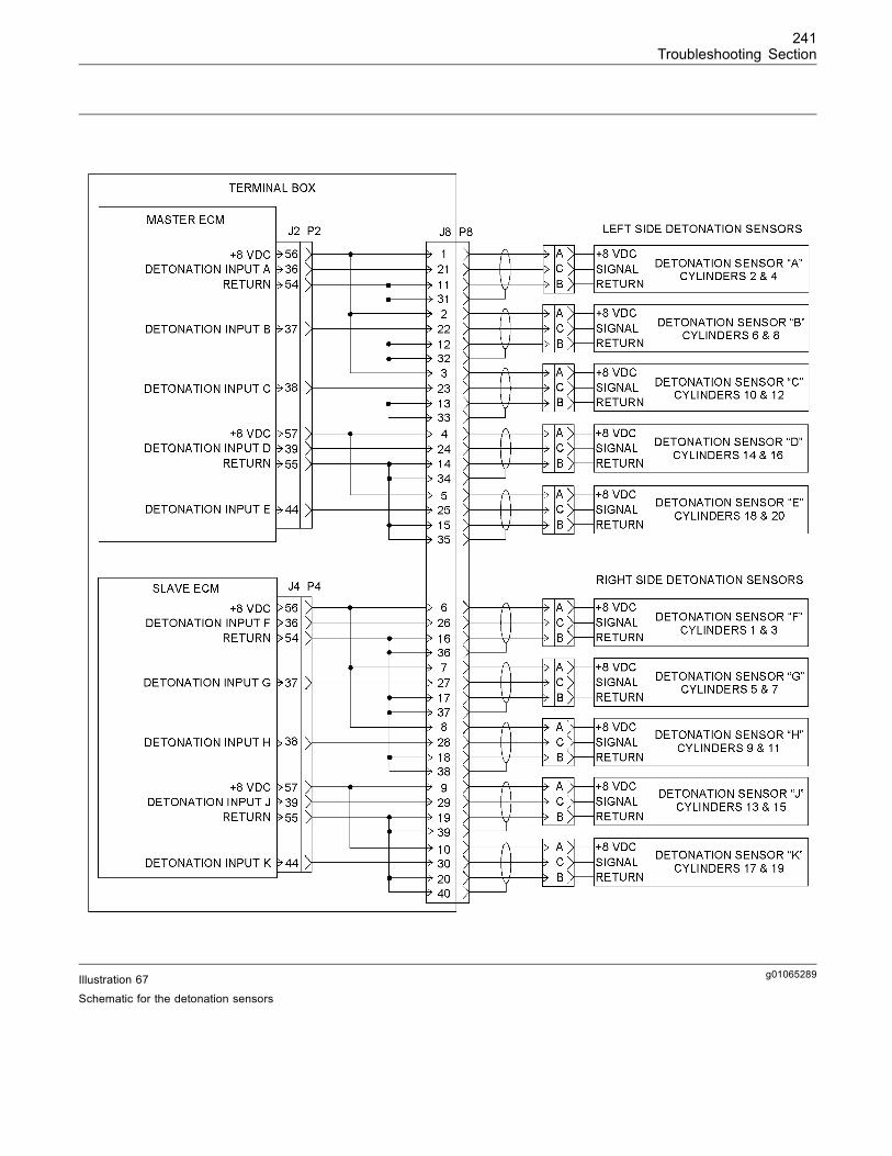
241Troubleshooting Section
g01065289Illustration 67
Schematic for the detonation sensors
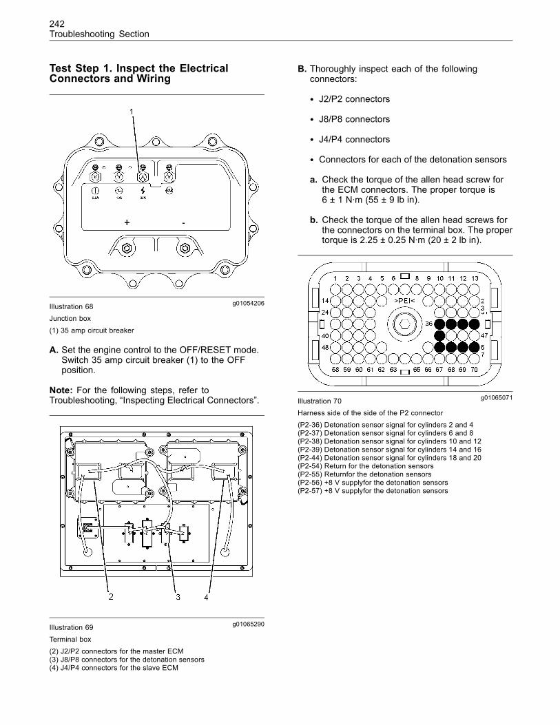
242Troubleshooting Section
Test Step 1. Inspect the ElectricalConnectors and Wiring
g01054206Illustration 68Junction box
(1) 35 amp circuit breaker
A. Set the engine control to the OFF/RESET mode.Switch 35 amp circuit breaker (1) to the OFFposition.
Note: For the following steps, refer toTroubleshooting, “Inspecting Electrical Connectors”.
g01065290Illustration 69
Terminal box
(2) J2/P2 connectors for the master ECM(3) J8/P8 connectors for the detonation sensors(4) J4/P4 connectors for the slave ECM
B. Thoroughly inspect each of the followingconnectors:
• J2/P2 connectors
• J8/P8 connectors
• J4/P4 connectors
• Connectors for each of the detonation sensors
a. Check the torque of the allen head screw forthe ECM connectors. The proper torque is6 ± 1 N·m (55 ± 9 lb in).
b. Check the torque of the allen head screws forthe connectors on the terminal box. The propertorque is 2.25 ± 0.25 N·m (20 ± 2 lb in).
g01065071Illustration 70Harness side of the side of the P2 connector(P2-36) Detonation sensor signal for cylinders 2 and 4(P2-37) Detonation sensor signal for cylinders 6 and 8(P2-38) Detonation sensor signal for cylinders 10 and 12(P2-39) Detonation sensor signal for cylinders 14 and 16(P2-44) Detonation sensor signal for cylinders 18 and 20(P2-54) Return for the detonation sensors(P2-55) Returnfor the detonation sensors(P2-56) +8 V supplyfor the detonation sensors(P2-57) +8 V supplyfor the detonation sensors
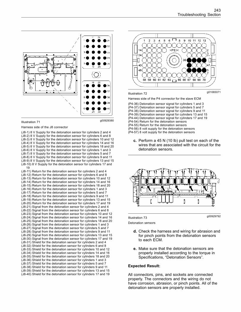
243Troubleshooting Section
g00929380Illustration 71
Harness side of the J8 connector(J8-1) 8 V Supply for the detonation sensor for cylinders 2 and 4(J8-2) 8 V Supply for the detonation sensor for cylinders 6 and 8(J8-3) 8 V Supply for the detonation sensor for cylinders 10 and 12(J8-4) 8 V Supply for the detonation sensor for cylinders 14 and 16(J8-5) 8 V Supply for the detonation sensor for cylinders 18 and 20(J8-6) 8 V Supply for the detonation sensor for cylinders 1 and 3(J8-7) 8 V Supply for the detonation sensor for cylinders 5 and 7(J8-8) 8 V Supply for the detonation sensor for cylinders 9 and 11(J8-9) 8 V Supply for the detonation sensor for cylinders 13 and 15(J8-10) 8 V Supply for the detonation sensor for cylinders 17 and
19(J8-11) Return for the detonation sensor for cylinders 2 and 4(J8-12) Return for the detonation sensor for cylinders 6 and 8(J8-13) Return for the detonation sensor for cylinders 10 and 12(J8-14) Return for the detonation sensor for cylinders 14 and 16(J8-15) Return for the detonation sensor for cylinders 18 and 20(J8-16) Return for the detonation sensor for cylinders 1 and 3(J8-17) Return for the detonation sensor for cylinders 5 and 7(J8-18) Return for the detonation sensor for cylinders 9 and 11(J8-19) Return for the detonation sensor for cylinders 13 and 15(J8-20) Return for the detonation sensor for cylinders 17 and 19(J8-21) Signal from the detonation sensor for cylinders 2 and 4(J8-22) Signal from the detonation sensor for cylinders 6 and 8(J8-23) Signal from the detonation sensor for cylinders 10 and 12(J8-24) Signal from the detonation sensor for cylinders 14 and 16(J8-25) Signal from the detonation sensor for cylinders 18 and 20(J8-26) Signal from the detonation sensor for cylinders 1 and 3(J8-27) Signal from the detonation sensor for cylinders 5 and 7(J8-28) Signal from the detonation sensor for cylinders 9 and 11(J8-29) Signal from the detonation sensor for cylinders 13 and 15(J8-30) Signal from the detonation sensor for cylinders 17 and 19(J8-31) Shield for the detonation sensor for cylinders 2 and 4(J8-32) Shield for the detonation sensor for cylinders 6 and 8(J8-33) Shield for the detonation sensor for cylinders 10 and 12(J8-34) Shield for the detonation sensor for cylinders 14 and 16(J8-35) Shield for the detonation sensor for cylinders 18 and 20(J8-36) Shield for the detonation sensor for cylinders 1 and 3(J8-37) Shield for the detonation sensor for cylinders 5 and 7(J8-38) Shield for the detonation sensor for cylinders 9 and 11(J8-39) Shield for the detonation sensor for cylinders 13 and 15(J8-40) Shield for the detonation sensor for cylinders 17 and 19
g01065071Illustration 72Harness side of the P4 connector for the slave ECM
(P4-36) Detonation sensor signal for cylinders 1 and 3(P4-37) Detonation sensor signal for cylinders 5 and 7(P4-38) Detonation sensor signal for cylinders 9 and 11(P4-39) Detonation sensor signal for cylinders 13 and 15(P4-44) Detonation sensor signal for cylinders 17 and 19(P4-54) Return for the detonation sensors(P4-55) Return for the detonation sensors(P4-56) 8 volt supply for the detonation sensors(P4-57) 8 volt supply for the detonation sensors
c. Perform a 45 N (10 lb) pull test on each of thewires that are associated with the circuit for thedetonation sensors.
g00929792Illustration 73
Detonation sensors
d. Check the harness and wiring for abrasion andfor pinch points from the detonation sensorsto each ECM.
e. Make sure that the detonation sensors areproperly installed according to the torque inSpecifications, “Detonation Sensors”.
Expected Result:
All connectors, pins, and sockets are connectedproperly. The connectors and the wiring do nothave corrosion, abrasion, or pinch points. All of thedetonation sensors are properly installed.
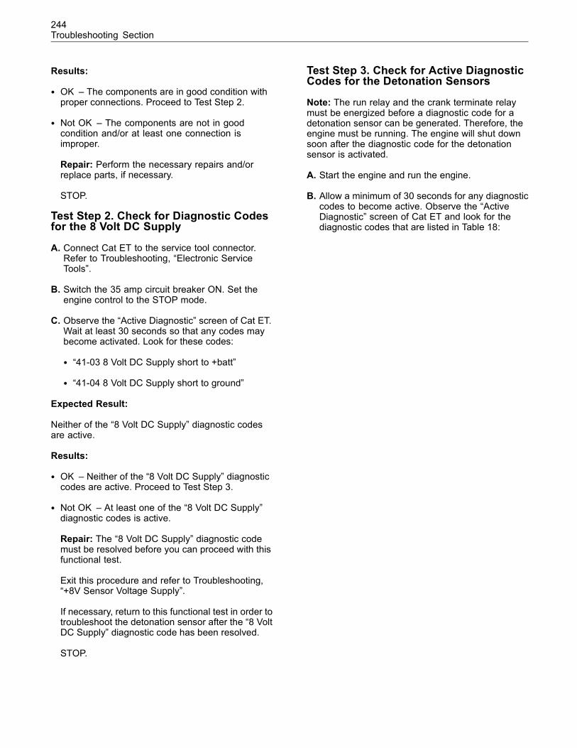
244Troubleshooting Section
Results:
• OK – The components are in good condition withproper connections. Proceed to Test Step 2.
• Not OK – The components are not in goodcondition and/or at least one connection isimproper.
Repair: Perform the necessary repairs and/orreplace parts, if necessary.
STOP.
Test Step 2. Check for Diagnostic Codesfor the 8 Volt DC Supply
A. Connect Cat ET to the service tool connector.Refer to Troubleshooting, “Electronic ServiceTools”.
B. Switch the 35 amp circuit breaker ON. Set theengine control to the STOP mode.
C. Observe the “Active Diagnostic” screen of Cat ET.Wait at least 30 seconds so that any codes maybecome activated. Look for these codes:
• “41-03 8 Volt DC Supply short to +batt”
• “41-04 8 Volt DC Supply short to ground”
Expected Result:
Neither of the “8 Volt DC Supply” diagnostic codesare active.
Results:
• OK – Neither of the “8 Volt DC Supply” diagnosticcodes are active. Proceed to Test Step 3.
• Not OK – At least one of the “8 Volt DC Supply”diagnostic codes is active.
Repair: The “8 Volt DC Supply” diagnostic codemust be resolved before you can proceed with thisfunctional test.
Exit this procedure and refer to Troubleshooting,“+8V Sensor Voltage Supply”.
If necessary, return to this functional test in order totroubleshoot the detonation sensor after the “8 VoltDC Supply” diagnostic code has been resolved.
STOP.
Test Step 3. Check for Active DiagnosticCodes for the Detonation Sensors
Note: The run relay and the crank terminate relaymust be energized before a diagnostic code for adetonation sensor can be generated. Therefore, theengine must be running. The engine will shut downsoon after the diagnostic code for the detonationsensor is activated.
A. Start the engine and run the engine.
B. Allow a minimum of 30 seconds for any diagnosticcodes to become active. Observe the “ActiveDiagnostic” screen of Cat ET and look for thediagnostic codes that are listed in Table 18:
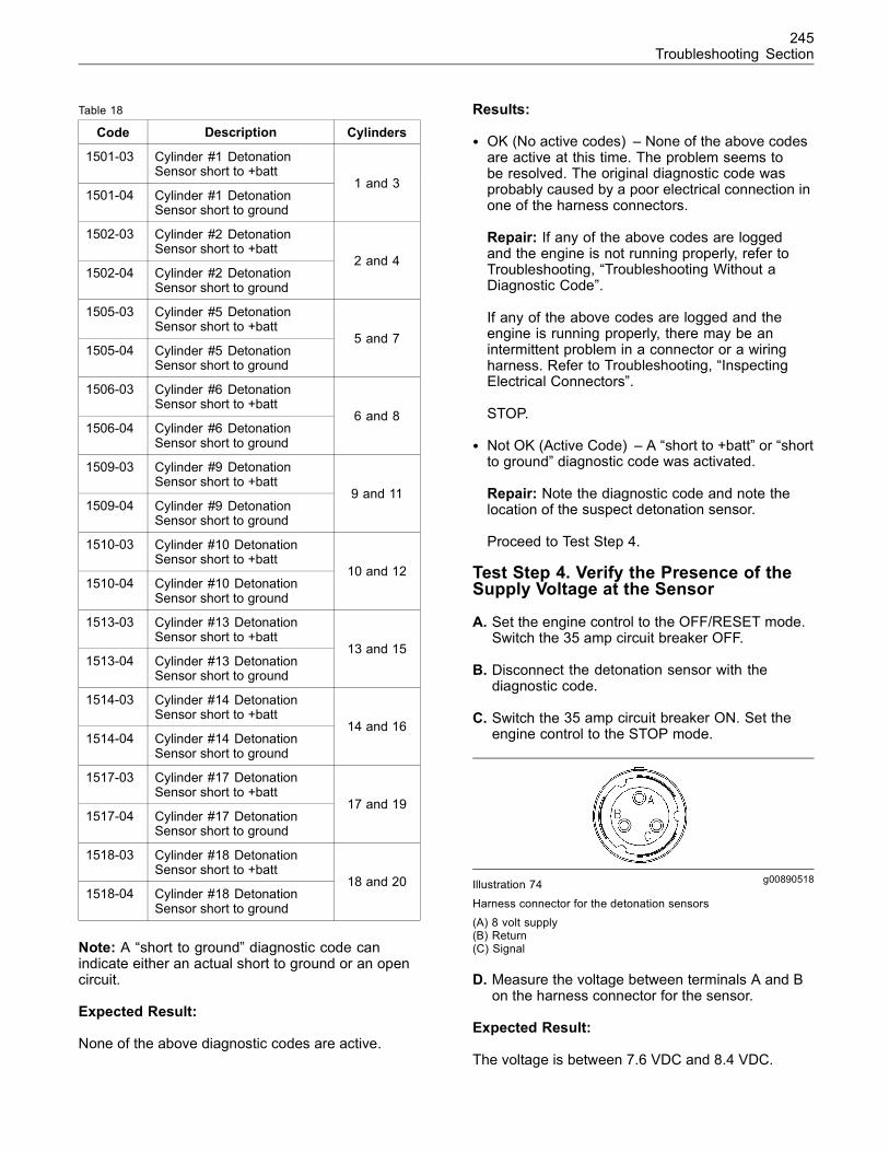
245Troubleshooting Section
Table 18
Code Description Cylinders
1501-03 Cylinder #1 DetonationSensor short to +batt
1501-04 Cylinder #1 DetonationSensor short to ground
1 and 3
1502-03 Cylinder #2 DetonationSensor short to +batt
1502-04 Cylinder #2 DetonationSensor short to ground
2 and 4
1505-03 Cylinder #5 DetonationSensor short to +batt
1505-04 Cylinder #5 DetonationSensor short to ground
5 and 7
1506-03 Cylinder #6 DetonationSensor short to +batt
1506-04 Cylinder #6 DetonationSensor short to ground
6 and 8
1509-03 Cylinder #9 DetonationSensor short to +batt
1509-04 Cylinder #9 DetonationSensor short to ground
9 and 11
1510-03 Cylinder #10 DetonationSensor short to +batt
1510-04 Cylinder #10 DetonationSensor short to ground
10 and 12
1513-03 Cylinder #13 DetonationSensor short to +batt
1513-04 Cylinder #13 DetonationSensor short to ground
13 and 15
1514-03 Cylinder #14 DetonationSensor short to +batt
1514-04 Cylinder #14 DetonationSensor short to ground
14 and 16
1517-03 Cylinder #17 DetonationSensor short to +batt
1517-04 Cylinder #17 DetonationSensor short to ground
17 and 19
1518-03 Cylinder #18 DetonationSensor short to +batt
1518-04 Cylinder #18 DetonationSensor short to ground
18 and 20
Note: A “short to ground” diagnostic code canindicate either an actual short to ground or an opencircuit.
Expected Result:
None of the above diagnostic codes are active.
Results:
• OK (No active codes) – None of the above codesare active at this time. The problem seems tobe resolved. The original diagnostic code wasprobably caused by a poor electrical connection inone of the harness connectors.
Repair: If any of the above codes are loggedand the engine is not running properly, refer toTroubleshooting, “Troubleshooting Without aDiagnostic Code”.
If any of the above codes are logged and theengine is running properly, there may be anintermittent problem in a connector or a wiringharness. Refer to Troubleshooting, “InspectingElectrical Connectors”.
STOP.
• Not OK (Active Code) – A “short to +batt” or “shortto ground” diagnostic code was activated.
Repair: Note the diagnostic code and note thelocation of the suspect detonation sensor.
Proceed to Test Step 4.
Test Step 4. Verify the Presence of theSupply Voltage at the Sensor
A. Set the engine control to the OFF/RESET mode.Switch the 35 amp circuit breaker OFF.
B. Disconnect the detonation sensor with thediagnostic code.
C. Switch the 35 amp circuit breaker ON. Set theengine control to the STOP mode.
g00890518Illustration 74
Harness connector for the detonation sensors(A) 8 volt supply(B) Return(C) Signal
D. Measure the voltage between terminals A and Bon the harness connector for the sensor.
Expected Result:
The voltage is between 7.6 VDC and 8.4 VDC.
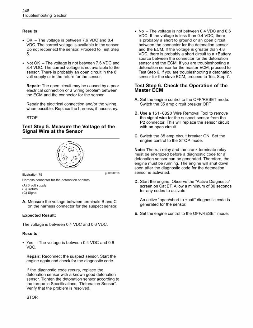
246Troubleshooting Section
Results:
• OK – The voltage is between 7.6 VDC and 8.4VDC. The correct voltage is available to the sensor.Do not reconnect the sensor. Proceed to Test Step5.
• Not OK – The voltage is not between 7.6 VDC and8.4 VDC. The correct voltage is not available to thesensor. There is probably an open circuit in the 8volt supply or in the return for the sensor.
Repair: The open circuit may be caused by a poorelectrical connection or a wiring problem betweenthe ECM and the connector for the sensor.
Repair the electrical connection and/or the wiring,when possible. Replace the harness, if necessary.
STOP.
Test Step 5. Measure the Voltage of theSignal Wire at the Sensor
g00890518Illustration 75Harness connector for the detonation sensors(A) 8 volt supply(B) Return(C) Signal
A. Measure the voltage between terminals B and Con the harness connector for the suspect sensor.
Expected Result:
The voltage is between 0.4 VDC and 0.6 VDC.
Results:
• Yes – The voltage is between 0.4 VDC and 0.6VDC.
Repair: Reconnect the suspect sensor. Start theengine again and check for the diagnostic code.
If the diagnostic code recurs, replace thedetonation sensor with a known good detonationsensor. Tighten the detonation sensor according tothe torque in Specifications, “Detonation Sensor”.Verify that the problem is resolved.
STOP.
• No – The voltage is not between 0.4 VDC and 0.6VDC. If the voltage is less than 0.4 VDC, thereis probably a short to ground or an open circuitbetween the connector for the detonation sensorand the ECM. If the voltage is greater than 4.8VDC, there is probably a short circuit to a +Batterysource between the connector for the detonationsensor and the ECM. If you are troubleshooting adetonation sensor for the master ECM, proceed toTest Step 6. If you are troubleshooting a detonationsensor for the slave ECM, proceed to Test Step 7.
Test Step 6. Check the Operation of theMaster ECM
A. Set the engine control to the OFF/RESET mode.Switch the 35 amp circuit breaker OFF.
B. Use a 151-6320 Wire Removal Tool to removethe signal wire for the suspect sensor from theP2 connector. This will replace the sensor circuitwith an open circuit.
C. Switch the 35 amp circuit breaker ON. Set theengine control to the STOP mode.
Note: The run relay and the crank terminate relaymust be energized before a diagnostic code for adetonation sensor can be generated. Therefore, theengine must be running. The engine will shut downsoon after the diagnostic code for the detonationsensor is activated.
D. Start the engine. Observe the “Active Diagnostic”screen on Cat ET. Allow a minimum of 30 secondsfor any codes to activate.
An active “open/short to +batt” diagnostic code isgenerated for the sensor.
E. Set the engine control to the OFF/RESET mode.
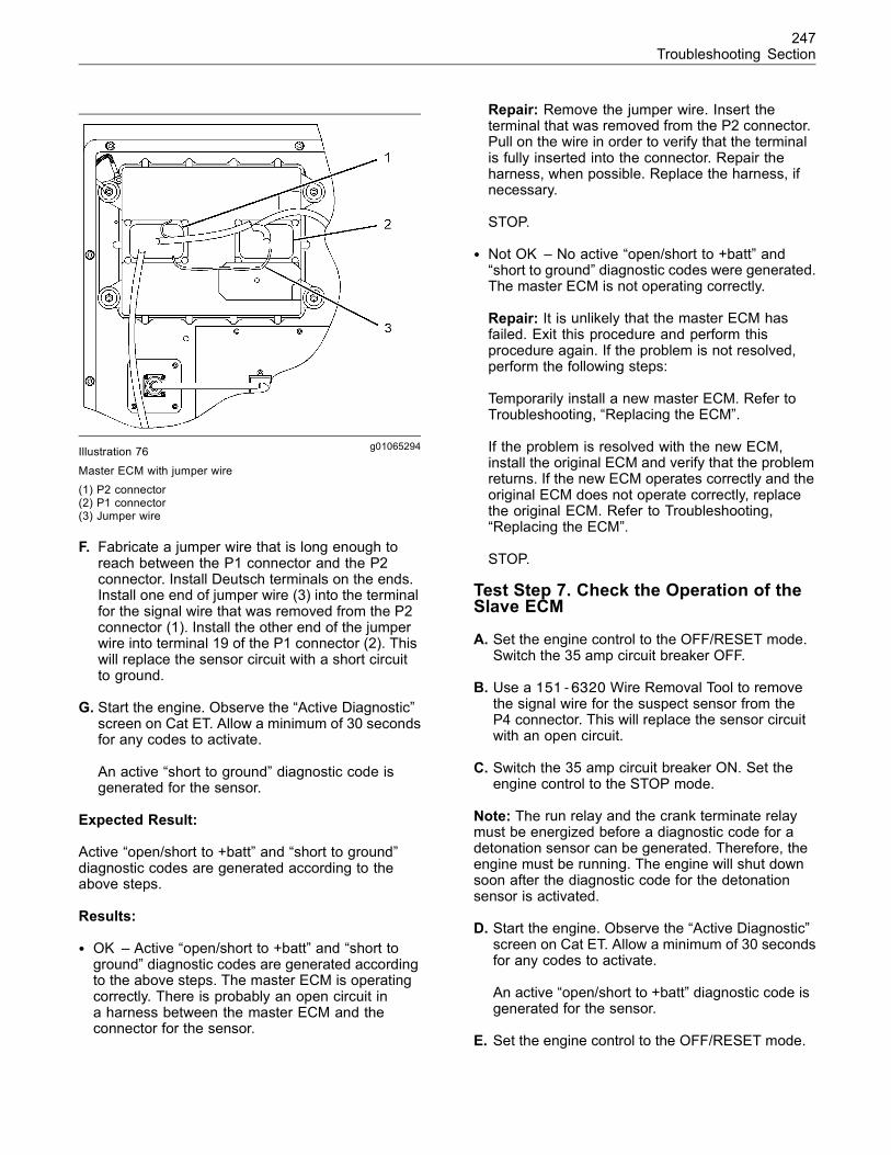
247Troubleshooting Section
g01065294Illustration 76
Master ECM with jumper wire(1) P2 connector(2) P1 connector(3) Jumper wire
F. Fabricate a jumper wire that is long enough toreach between the P1 connector and the P2connector. Install Deutsch terminals on the ends.Install one end of jumper wire (3) into the terminalfor the signal wire that was removed from the P2connector (1). Install the other end of the jumperwire into terminal 19 of the P1 connector (2). Thiswill replace the sensor circuit with a short circuitto ground.
G. Start the engine. Observe the “Active Diagnostic”screen on Cat ET. Allow a minimum of 30 secondsfor any codes to activate.
An active “short to ground” diagnostic code isgenerated for the sensor.
Expected Result:
Active “open/short to +batt” and “short to ground”diagnostic codes are generated according to theabove steps.
Results:
• OK – Active “open/short to +batt” and “short toground” diagnostic codes are generated accordingto the above steps. The master ECM is operatingcorrectly. There is probably an open circuit ina harness between the master ECM and theconnector for the sensor.
Repair: Remove the jumper wire. Insert theterminal that was removed from the P2 connector.Pull on the wire in order to verify that the terminalis fully inserted into the connector. Repair theharness, when possible. Replace the harness, ifnecessary.
STOP.
• Not OK – No active “open/short to +batt” and“short to ground” diagnostic codes were generated.The master ECM is not operating correctly.
Repair: It is unlikely that the master ECM hasfailed. Exit this procedure and perform thisprocedure again. If the problem is not resolved,perform the following steps:
Temporarily install a new master ECM. Refer toTroubleshooting, “Replacing the ECM”.
If the problem is resolved with the new ECM,install the original ECM and verify that the problemreturns. If the new ECM operates correctly and theoriginal ECM does not operate correctly, replacethe original ECM. Refer to Troubleshooting,“Replacing the ECM”.
STOP.
Test Step 7. Check the Operation of theSlave ECM
A. Set the engine control to the OFF/RESET mode.Switch the 35 amp circuit breaker OFF.
B. Use a 151-6320 Wire Removal Tool to removethe signal wire for the suspect sensor from theP4 connector. This will replace the sensor circuitwith an open circuit.
C. Switch the 35 amp circuit breaker ON. Set theengine control to the STOP mode.
Note: The run relay and the crank terminate relaymust be energized before a diagnostic code for adetonation sensor can be generated. Therefore, theengine must be running. The engine will shut downsoon after the diagnostic code for the detonationsensor is activated.
D. Start the engine. Observe the “Active Diagnostic”screen on Cat ET. Allow a minimum of 30 secondsfor any codes to activate.
An active “open/short to +batt” diagnostic code isgenerated for the sensor.
E. Set the engine control to the OFF/RESET mode.
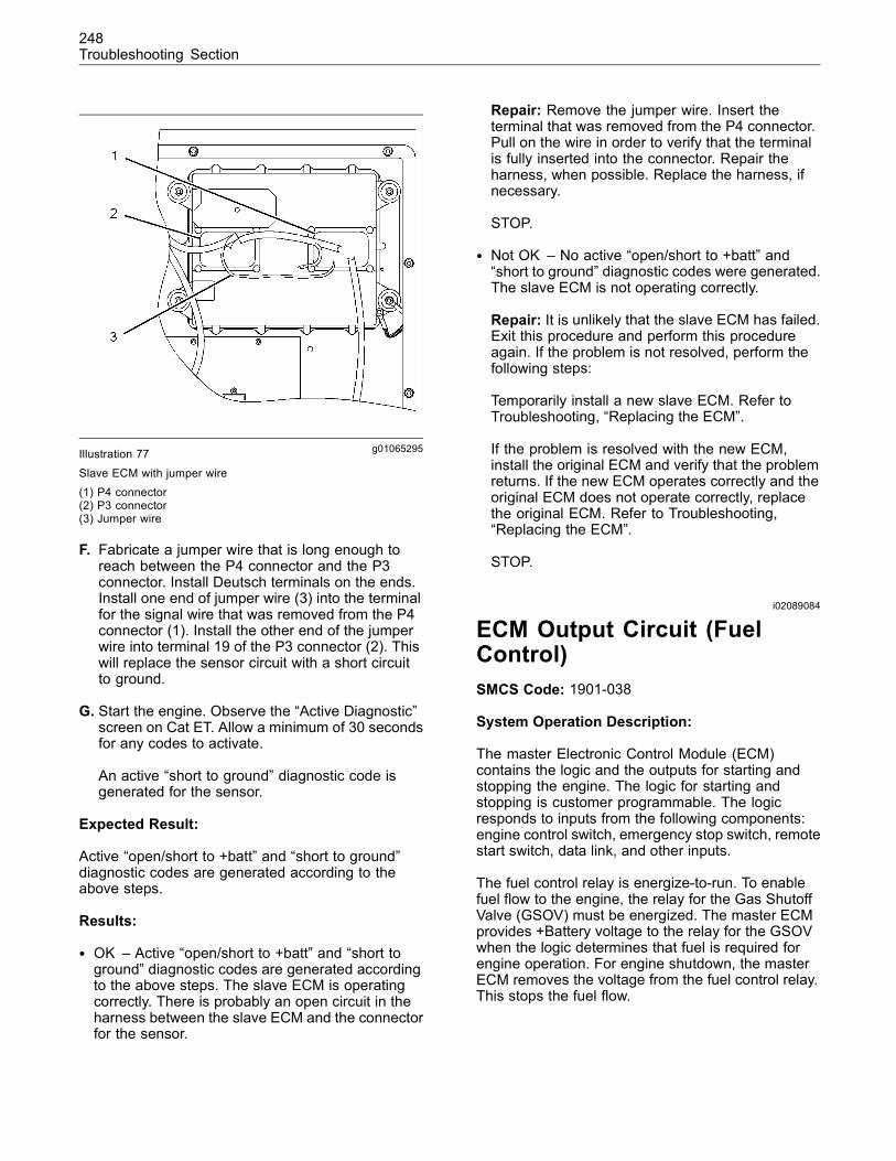
248Troubleshooting Section
g01065295Illustration 77
Slave ECM with jumper wire(1) P4 connector(2) P3 connector(3) Jumper wire
F. Fabricate a jumper wire that is long enough toreach between the P4 connector and the P3connector. Install Deutsch terminals on the ends.Install one end of jumper wire (3) into the terminalfor the signal wire that was removed from the P4connector (1). Install the other end of the jumperwire into terminal 19 of the P3 connector (2). Thiswill replace the sensor circuit with a short circuitto ground.
G. Start the engine. Observe the “Active Diagnostic”screen on Cat ET. Allow a minimum of 30 secondsfor any codes to activate.
An active “short to ground” diagnostic code isgenerated for the sensor.
Expected Result:
Active “open/short to +batt” and “short to ground”diagnostic codes are generated according to theabove steps.
Results:
• OK – Active “open/short to +batt” and “short toground” diagnostic codes are generated accordingto the above steps. The slave ECM is operatingcorrectly. There is probably an open circuit in theharness between the slave ECM and the connectorfor the sensor.
Repair: Remove the jumper wire. Insert theterminal that was removed from the P4 connector.Pull on the wire in order to verify that the terminalis fully inserted into the connector. Repair theharness, when possible. Replace the harness, ifnecessary.
STOP.
• Not OK – No active “open/short to +batt” and“short to ground” diagnostic codes were generated.The slave ECM is not operating correctly.
Repair: It is unlikely that the slave ECM has failed.Exit this procedure and perform this procedureagain. If the problem is not resolved, perform thefollowing steps:
Temporarily install a new slave ECM. Refer toTroubleshooting, “Replacing the ECM”.
If the problem is resolved with the new ECM,install the original ECM and verify that the problemreturns. If the new ECM operates correctly and theoriginal ECM does not operate correctly, replacethe original ECM. Refer to Troubleshooting,“Replacing the ECM”.
STOP.
i02089084
ECM Output Circuit (FuelControl)SMCS Code: 1901-038
System Operation Description:
The master Electronic Control Module (ECM)contains the logic and the outputs for starting andstopping the engine. The logic for starting andstopping is customer programmable. The logicresponds to inputs from the following components:engine control switch, emergency stop switch, remotestart switch, data link, and other inputs.
The fuel control relay is energize-to-run. To enablefuel flow to the engine, the relay for the Gas ShutoffValve (GSOV) must be energized. The master ECMprovides +Battery voltage to the relay for the GSOVwhen the logic determines that fuel is required forengine operation. For engine shutdown, the masterECM removes the voltage from the fuel control relay.This stops the fuel flow.
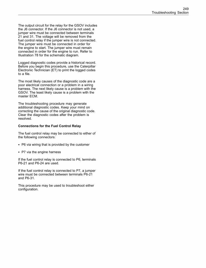
249Troubleshooting Section
The output circuit for the relay for the GSOV includesthe J6 connector. If the J6 connector is not used, ajumper wire must be connected between terminals21 and 31. The voltage will be removed from thefuel control relay if the jumper wire is not connected.The jumper wire must be connected in order forthe engine to start. The jumper wire must remainconnected in order for the engine to run. Refer toIllustration 78 for the schematic diagram.
Logged diagnostic codes provide a historical record.Before you begin this procedure, use the CaterpillarElectronic Technician (ET) to print the logged codesto a file.
The most likely causes of the diagnostic code are apoor electrical connection or a problem in a wiringharness. The next likely cause is a problem with theGSOV. The least likely cause is a problem with themaster ECM.
The troubleshooting procedure may generateadditional diagnostic codes. Keep your mind oncorrecting the cause of the original diagnostic code.Clear the diagnostic codes after the problem isresolved.
Connections for the Fuel Control Relay
The fuel control relay may be connected to either ofthe following connectors:
• P6 via wiring that is provided by the customer
• P7 via the engine harness
If the fuel control relay is connected to P6, terminalsP6-21 and P6-24 are used.
If the fuel control relay is connected to P7, a jumperwire must be connected between terminals P6-21and P6-31.
This procedure may be used to troubleshoot eitherconfiguration.
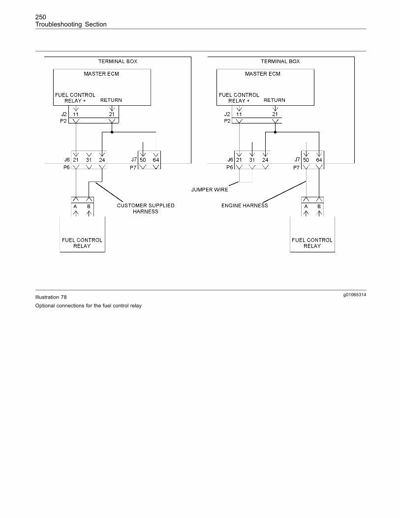
250Troubleshooting Section
g01065314Illustration 78Optional connections for the fuel control relay
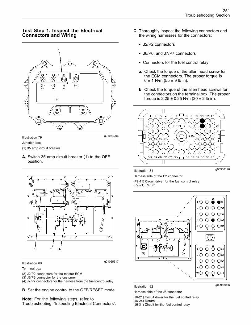
251Troubleshooting Section
Test Step 1. Inspect the ElectricalConnectors and Wiring
g01054206Illustration 79Junction box
(1) 35 amp circuit breaker
A. Switch 35 amp circuit breaker (1) to the OFFposition.
g01065317Illustration 80Terminal box(2) J2/P2 connectors for the master ECM(3) J6/P6 connector for the customer(4) J7/P7 connectors for the harness from the fuel control relay
B. Set the engine control to the OFF/RESET mode.
Note: For the following steps, refer toTroubleshooting, “Inspecting Electrical Connectors”.
C. Thoroughly inspect the following connectors andthe wiring harnesses for the connectors:
• J2/P2 connectors
• J6/P6, and J7/P7 connectors
• Connectors for the fuel control relay
a. Check the torque of the allen head screw forthe ECM connectors. The proper torque is6 ± 1 N·m (55 ± 9 lb in).
b. Check the torque of the allen head screws forthe connectors on the terminal box. The propertorque is 2.25 ± 0.25 N·m (20 ± 2 lb in).
g00930126Illustration 81
Harness side of the P2 connector(P2-11) Circuit driver for the fuel control relay(P2-21) Return
g00952066Illustration 82
Harness side of the J6 connector(J6-21) Circuit driver for the fuel control relay(J6-24) Return(J6-31) Circuit for the fuel control relay
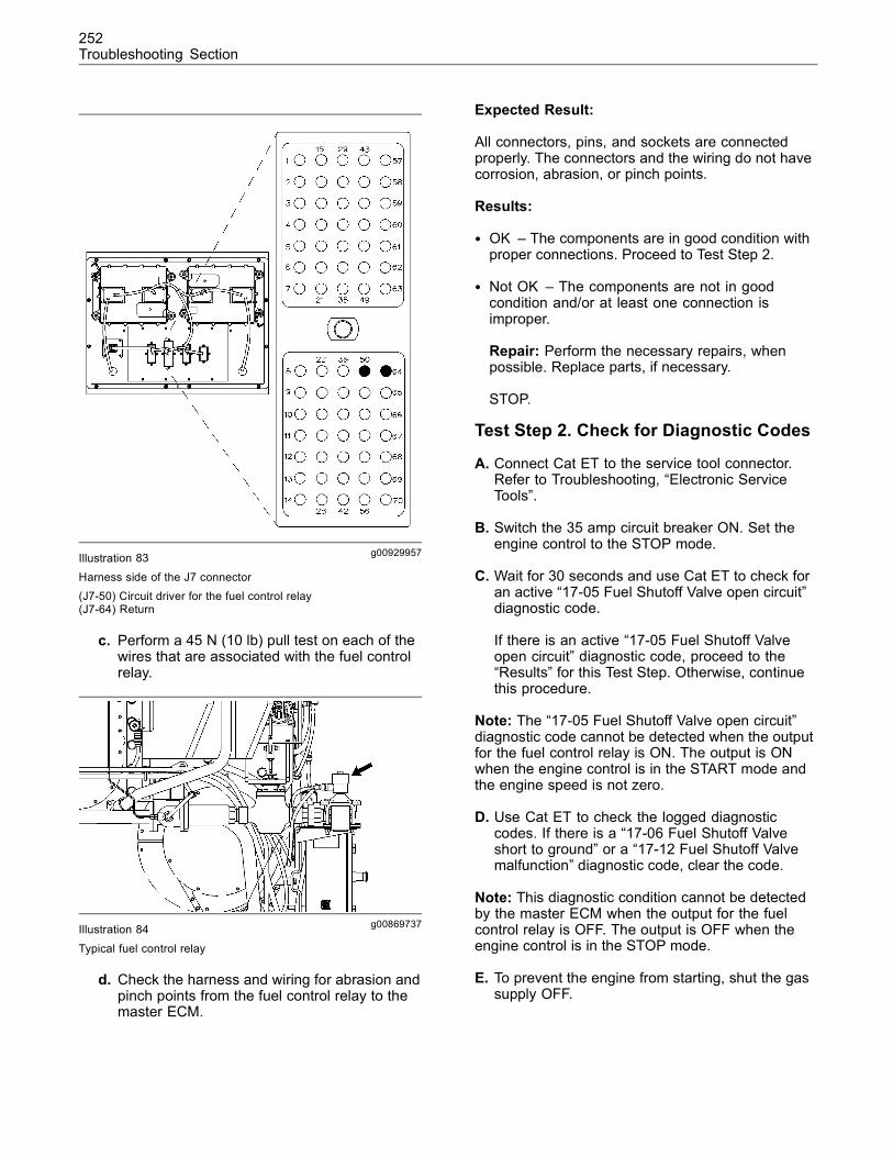
252Troubleshooting Section
g00929957Illustration 83
Harness side of the J7 connector(J7-50) Circuit driver for the fuel control relay(J7-64) Return
c. Perform a 45 N (10 lb) pull test on each of thewires that are associated with the fuel controlrelay.
g00869737Illustration 84
Typical fuel control relay
d. Check the harness and wiring for abrasion andpinch points from the fuel control relay to themaster ECM.
Expected Result:
All connectors, pins, and sockets are connectedproperly. The connectors and the wiring do not havecorrosion, abrasion, or pinch points.
Results:
• OK – The components are in good condition withproper connections. Proceed to Test Step 2.
• Not OK – The components are not in goodcondition and/or at least one connection isimproper.
Repair: Perform the necessary repairs, whenpossible. Replace parts, if necessary.
STOP.
Test Step 2. Check for Diagnostic Codes
A. Connect Cat ET to the service tool connector.Refer to Troubleshooting, “Electronic ServiceTools”.
B. Switch the 35 amp circuit breaker ON. Set theengine control to the STOP mode.
C. Wait for 30 seconds and use Cat ET to check foran active “17-05 Fuel Shutoff Valve open circuit”diagnostic code.
If there is an active “17-05 Fuel Shutoff Valveopen circuit” diagnostic code, proceed to the“Results” for this Test Step. Otherwise, continuethis procedure.
Note: The “17-05 Fuel Shutoff Valve open circuit”diagnostic code cannot be detected when the outputfor the fuel control relay is ON. The output is ONwhen the engine control is in the START mode andthe engine speed is not zero.
D. Use Cat ET to check the logged diagnosticcodes. If there is a “17-06 Fuel Shutoff Valveshort to ground” or a “17-12 Fuel Shutoff Valvemalfunction” diagnostic code, clear the code.
Note: This diagnostic condition cannot be detectedby the master ECM when the output for the fuelcontrol relay is OFF. The output is OFF when theengine control is in the STOP mode.
E. To prevent the engine from starting, shut the gassupply OFF.
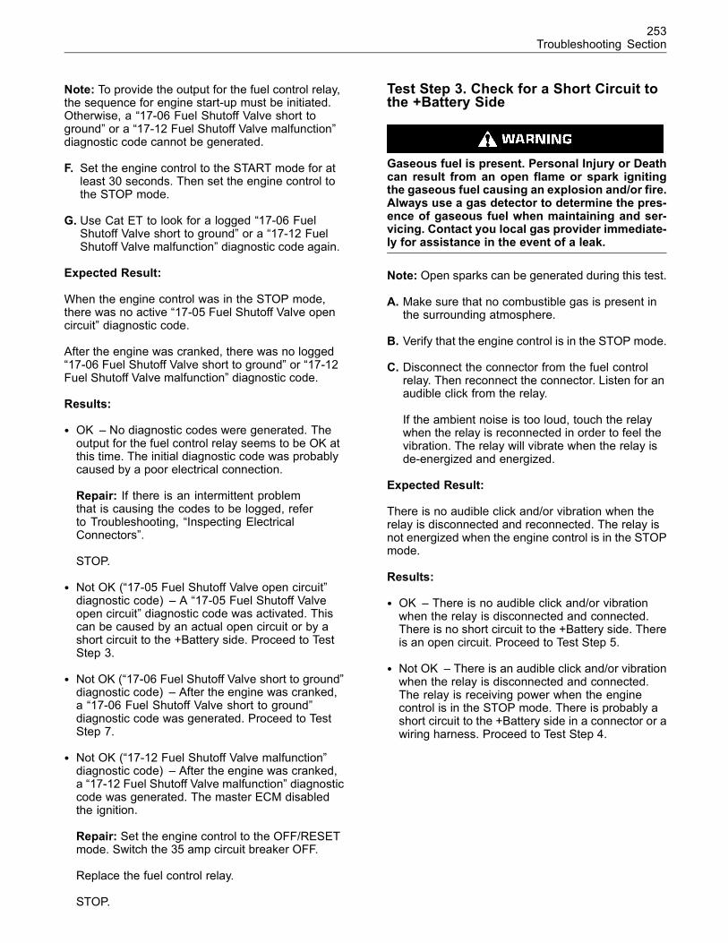
253Troubleshooting Section
Note: To provide the output for the fuel control relay,the sequence for engine start-up must be initiated.Otherwise, a “17-06 Fuel Shutoff Valve short toground” or a “17-12 Fuel Shutoff Valve malfunction”diagnostic code cannot be generated.
F. Set the engine control to the START mode for atleast 30 seconds. Then set the engine control tothe STOP mode.
G. Use Cat ET to look for a logged “17-06 FuelShutoff Valve short to ground” or a “17-12 FuelShutoff Valve malfunction” diagnostic code again.
Expected Result:
When the engine control was in the STOP mode,there was no active “17-05 Fuel Shutoff Valve opencircuit” diagnostic code.
After the engine was cranked, there was no logged“17-06 Fuel Shutoff Valve short to ground” or “17-12Fuel Shutoff Valve malfunction” diagnostic code.
Results:
• OK – No diagnostic codes were generated. Theoutput for the fuel control relay seems to be OK atthis time. The initial diagnostic code was probablycaused by a poor electrical connection.
Repair: If there is an intermittent problemthat is causing the codes to be logged, referto Troubleshooting, “Inspecting ElectricalConnectors”.
STOP.
• Not OK (“17-05 Fuel Shutoff Valve open circuit”diagnostic code) – A “17-05 Fuel Shutoff Valveopen circuit” diagnostic code was activated. Thiscan be caused by an actual open circuit or by ashort circuit to the +Battery side. Proceed to TestStep 3.
• Not OK (“17-06 Fuel Shutoff Valve short to ground”diagnostic code) – After the engine was cranked,a “17-06 Fuel Shutoff Valve short to ground”diagnostic code was generated. Proceed to TestStep 7.
• Not OK (“17-12 Fuel Shutoff Valve malfunction”diagnostic code) – After the engine was cranked,a “17-12 Fuel Shutoff Valve malfunction” diagnosticcode was generated. The master ECM disabledthe ignition.
Repair: Set the engine control to the OFF/RESETmode. Switch the 35 amp circuit breaker OFF.
Replace the fuel control relay.
STOP.
Test Step 3. Check for a Short Circuit tothe +Battery Side
Gaseous fuel is present. Personal Injury or Deathcan result from an open flame or spark ignitingthe gaseous fuel causing an explosion and/or fire.Always use a gas detector to determine the pres-ence of gaseous fuel when maintaining and ser-vicing. Contact you local gas provider immediate-ly for assistance in the event of a leak.
Note: Open sparks can be generated during this test.
A. Make sure that no combustible gas is present inthe surrounding atmosphere.
B. Verify that the engine control is in the STOP mode.
C. Disconnect the connector from the fuel controlrelay. Then reconnect the connector. Listen for anaudible click from the relay.
If the ambient noise is too loud, touch the relaywhen the relay is reconnected in order to feel thevibration. The relay will vibrate when the relay isde-energized and energized.
Expected Result:
There is no audible click and/or vibration when therelay is disconnected and reconnected. The relay isnot energized when the engine control is in the STOPmode.
Results:
• OK – There is no audible click and/or vibrationwhen the relay is disconnected and connected.There is no short circuit to the +Battery side. Thereis an open circuit. Proceed to Test Step 5.
• Not OK – There is an audible click and/or vibrationwhen the relay is disconnected and connected.The relay is receiving power when the enginecontrol is in the STOP mode. There is probably ashort circuit to the +Battery side in a connector or awiring harness. Proceed to Test Step 4.
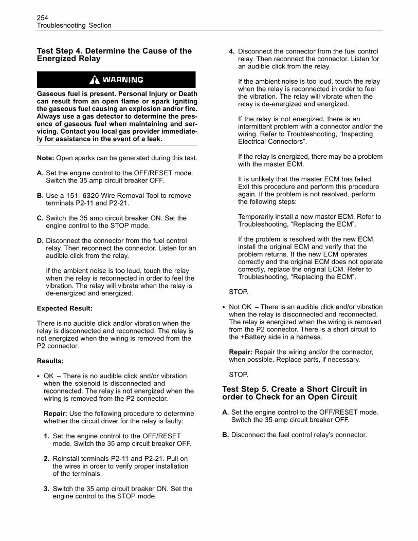
254Troubleshooting Section
Test Step 4. Determine the Cause of theEnergized Relay
Gaseous fuel is present. Personal Injury or Deathcan result from an open flame or spark ignitingthe gaseous fuel causing an explosion and/or fire.Always use a gas detector to determine the pres-ence of gaseous fuel when maintaining and ser-vicing. Contact you local gas provider immediate-ly for assistance in the event of a leak.
Note: Open sparks can be generated during this test.
A. Set the engine control to the OFF/RESET mode.Switch the 35 amp circuit breaker OFF.
B. Use a 151-6320 Wire Removal Tool to removeterminals P2-11 and P2-21.
C. Switch the 35 amp circuit breaker ON. Set theengine control to the STOP mode.
D. Disconnect the connector from the fuel controlrelay. Then reconnect the connector. Listen for anaudible click from the relay.
If the ambient noise is too loud, touch the relaywhen the relay is reconnected in order to feel thevibration. The relay will vibrate when the relay isde-energized and energized.
Expected Result:
There is no audible click and/or vibration when therelay is disconnected and reconnected. The relay isnot energized when the wiring is removed from theP2 connector.
Results:
• OK – There is no audible click and/or vibrationwhen the solenoid is disconnected andreconnected. The relay is not energized when thewiring is removed from the P2 connector.
Repair: Use the following procedure to determinewhether the circuit driver for the relay is faulty:
1. Set the engine control to the OFF/RESETmode. Switch the 35 amp circuit breaker OFF.
2. Reinstall terminals P2-11 and P2-21. Pull onthe wires in order to verify proper installationof the terminals.
3. Switch the 35 amp circuit breaker ON. Set theengine control to the STOP mode.
4. Disconnect the connector from the fuel controlrelay. Then reconnect the connector. Listen foran audible click from the relay.
If the ambient noise is too loud, touch the relaywhen the relay is reconnected in order to feelthe vibration. The relay will vibrate when therelay is de-energized and energized.
If the relay is not energized, there is anintermittent problem with a connector and/or thewiring. Refer to Troubleshooting, “InspectingElectrical Connectors”.
If the relay is energized, there may be a problemwith the master ECM.
It is unlikely that the master ECM has failed.Exit this procedure and perform this procedureagain. If the problem is not resolved, performthe following steps:
Temporarily install a new master ECM. Refer toTroubleshooting, “Replacing the ECM”.
If the problem is resolved with the new ECM,install the original ECM and verify that theproblem returns. If the new ECM operatescorrectly and the original ECM does not operatecorrectly, replace the original ECM. Refer toTroubleshooting, “Replacing the ECM”.
STOP.
• Not OK – There is an audible click and/or vibrationwhen the relay is disconnected and reconnected.The relay is energized when the wiring is removedfrom the P2 connector. There is a short circuit tothe +Battery side in a harness.
Repair: Repair the wiring and/or the connector,when possible. Replace parts, if necessary.
STOP.
Test Step 5. Create a Short Circuit inorder to Check for an Open Circuit
A. Set the engine control to the OFF/RESET mode.Switch the 35 amp circuit breaker OFF.
B. Disconnect the fuel control relay’s connector.
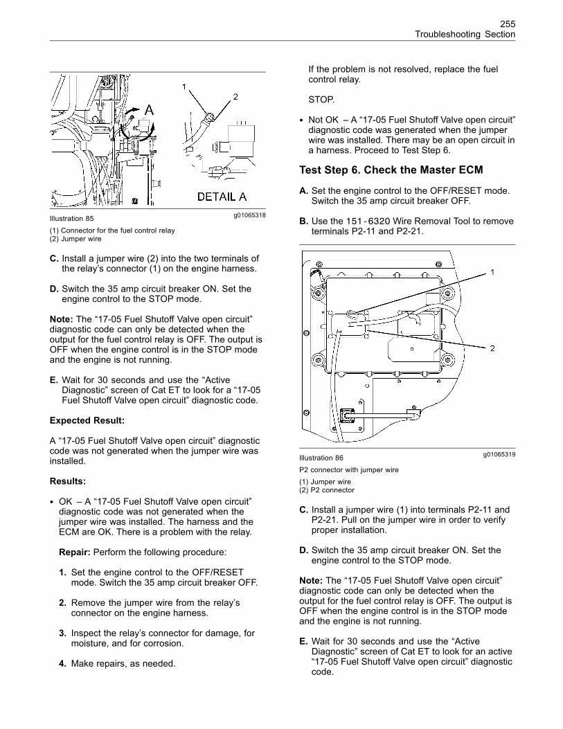
255Troubleshooting Section
g01065318Illustration 85(1) Connector for the fuel control relay(2) Jumper wire
C. Install a jumper wire (2) into the two terminals ofthe relay’s connector (1) on the engine harness.
D. Switch the 35 amp circuit breaker ON. Set theengine control to the STOP mode.
Note: The “17-05 Fuel Shutoff Valve open circuit”diagnostic code can only be detected when theoutput for the fuel control relay is OFF. The output isOFF when the engine control is in the STOP modeand the engine is not running.
E. Wait for 30 seconds and use the “ActiveDiagnostic” screen of Cat ET to look for a “17-05Fuel Shutoff Valve open circuit” diagnostic code.
Expected Result:
A “17-05 Fuel Shutoff Valve open circuit” diagnosticcode was not generated when the jumper wire wasinstalled.
Results:
• OK – A “17-05 Fuel Shutoff Valve open circuit”diagnostic code was not generated when thejumper wire was installed. The harness and theECM are OK. There is a problem with the relay.
Repair: Perform the following procedure:
1. Set the engine control to the OFF/RESETmode. Switch the 35 amp circuit breaker OFF.
2. Remove the jumper wire from the relay’sconnector on the engine harness.
3. Inspect the relay’s connector for damage, formoisture, and for corrosion.
4. Make repairs, as needed.
If the problem is not resolved, replace the fuelcontrol relay.
STOP.
• Not OK – A “17-05 Fuel Shutoff Valve open circuit”diagnostic code was generated when the jumperwire was installed. There may be an open circuit ina harness. Proceed to Test Step 6.
Test Step 6. Check the Master ECM
A. Set the engine control to the OFF/RESET mode.Switch the 35 amp circuit breaker OFF.
B. Use the 151-6320 Wire Removal Tool to removeterminals P2-11 and P2-21.
g01065319Illustration 86P2 connector with jumper wire(1) Jumper wire(2) P2 connector
C. Install a jumper wire (1) into terminals P2-11 andP2-21. Pull on the jumper wire in order to verifyproper installation.
D. Switch the 35 amp circuit breaker ON. Set theengine control to the STOP mode.
Note: The “17-05 Fuel Shutoff Valve open circuit”diagnostic code can only be detected when theoutput for the fuel control relay is OFF. The output isOFF when the engine control is in the STOP modeand the engine is not running.
E. Wait for 30 seconds and use the “ActiveDiagnostic” screen of Cat ET to look for an active“17-05 Fuel Shutoff Valve open circuit” diagnosticcode.
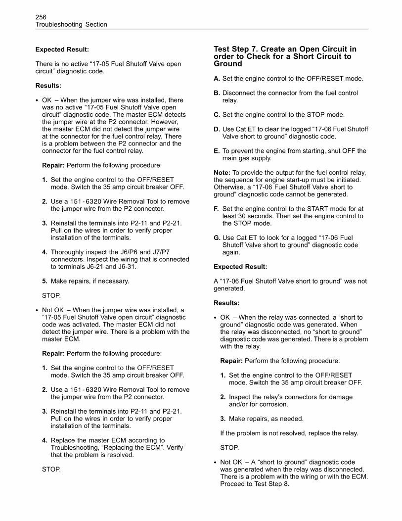
256Troubleshooting Section
Expected Result:
There is no active “17-05 Fuel Shutoff Valve opencircuit” diagnostic code.
Results:
• OK – When the jumper wire was installed, therewas no active “17-05 Fuel Shutoff Valve opencircuit” diagnostic code. The master ECM detectsthe jumper wire at the P2 connector. However,the master ECM did not detect the jumper wireat the connector for the fuel control relay. Thereis a problem between the P2 connector and theconnector for the fuel control relay.
Repair: Perform the following procedure:
1. Set the engine control to the OFF/RESETmode. Switch the 35 amp circuit breaker OFF.
2. Use a 151-6320Wire Removal Tool to removethe jumper wire from the P2 connector.
3. Reinstall the terminals into P2-11 and P2-21.Pull on the wires in order to verify properinstallation of the terminals.
4. Thoroughly inspect the J6/P6 and J7/P7connectors. Inspect the wiring that is connectedto terminals J6-21 and J6-31.
5. Make repairs, if necessary.
STOP.
• Not OK – When the jumper wire was installed, a“17-05 Fuel Shutoff Valve open circuit” diagnosticcode was activated. The master ECM did notdetect the jumper wire. There is a problem with themaster ECM.
Repair: Perform the following procedure:
1. Set the engine control to the OFF/RESETmode. Switch the 35 amp circuit breaker OFF.
2. Use a 151-6320Wire Removal Tool to removethe jumper wire from the P2 connector.
3. Reinstall the terminals into P2-11 and P2-21.Pull on the wires in order to verify properinstallation of the terminals.
4. Replace the master ECM according toTroubleshooting, “Replacing the ECM”. Verifythat the problem is resolved.
STOP.
Test Step 7. Create an Open Circuit inorder to Check for a Short Circuit toGround
A. Set the engine control to the OFF/RESET mode.
B. Disconnect the connector from the fuel controlrelay.
C. Set the engine control to the STOP mode.
D. Use Cat ET to clear the logged “17-06 Fuel ShutoffValve short to ground” diagnostic code.
E. To prevent the engine from starting, shut OFF themain gas supply.
Note: To provide the output for the fuel control relay,the sequence for engine start-up must be initiated.Otherwise, a “17-06 Fuel Shutoff Valve short toground” diagnostic code cannot be generated.
F. Set the engine control to the START mode for atleast 30 seconds. Then set the engine control tothe STOP mode.
G. Use Cat ET to look for a logged “17-06 FuelShutoff Valve short to ground” diagnostic codeagain.
Expected Result:
A “17-06 Fuel Shutoff Valve short to ground” was notgenerated.
Results:
• OK – When the relay was connected, a “short toground” diagnostic code was generated. Whenthe relay was disconnected, no “short to ground”diagnostic code was generated. There is a problemwith the relay.
Repair: Perform the following procedure:
1. Set the engine control to the OFF/RESETmode. Switch the 35 amp circuit breaker OFF.
2. Inspect the relay’s connectors for damageand/or for corrosion.
3. Make repairs, as needed.
If the problem is not resolved, replace the relay.
STOP.
• Not OK – A “short to ground” diagnostic codewas generated when the relay was disconnected.There is a problem with the wiring or with the ECM.Proceed to Test Step 8.
257Troubleshooting Section
Test Step 8. Check the Master ECM
A. Set the engine control to the OFF/RESET mode.Switch the 35 amp circuit breaker OFF.
B. Use the 151-6320Wire Removal Tool to removeterminal P2-11.
C. Switch the 35 amp circuit breaker ON. Set theengine control to the STOP mode.
D. Use Cat ET to clear the logged “17-06 Fuel ShutoffValve short to ground” diagnostic code.
E. To prevent the engine from starting, shut OFF themain gas supply.
Note: To provide the output for the fuel control relay,the sequence for engine start-up must be initiated.Otherwise, a “17-06 Fuel Shutoff Valve short toground” diagnostic code cannot be generated.
F. Set the engine control to the START mode for atleast 30 seconds. Then set the engine control tothe STOP mode.
G. Use Cat ET to look for a logged “17-06 FuelShutoff Valve short to ground” diagnostic codeagain.
Expected Result:
The “17-06 Fuel Shutoff Valve short to ground”diagnostic code was not generated.
Results:
• OK – When the output to the relay wasdisconnected from the P2 connector, the “17-06Fuel Shutoff Valve short to ground” diagnosticcode was not generated. However, a “short toground” diagnostic code was generated when theconnector was disconnected from the fuel controlrelay. There is a problem in the wiring between theP2 connector and the connector for the fuel controlrelay.
Repair: Perform the following procedure:
1. Set the engine control to the OFF/RESETmode. Switch the 35 amp circuit breaker OFF.
2. Reinstall the terminal that was removed fromP2-11. Pull on the wire in order to verify properinstallation of the terminal.
3. Repair the harness, when possible. Replacethe harness, if necessary.
STOP.
• Not OK – A “17-06 Fuel Shutoff Valve short toground” diagnostic code was generated when theoutput to the relay was disconnected from theP2 connector. There may be a problem with themaster ECM.
Repair: Perform the following procedure:
1. Set the engine control to the OFF/RESETmode. Switch the 35 amp circuit breaker OFF.
2. Reinstall the terminal that was removed fromP2-11. Pull on the wire in order to verify properinstallation of the terminal.
3. It is unlikely that the master ECM has failed.Exit this procedure and perform this procedureagain. If the problem is not resolved, performthe following steps:
Temporarily install a new master ECM. Refer toTroubleshooting, “Replacing the ECM”.
If the problem is resolved with the new ECM,install the original ECM and verify that theproblem returns. If the new ECM operatescorrectly and the original ECM does not operatecorrectly, replace the original ECM. Refer toTroubleshooting, “Replacing the ECM”.
STOP.
i02089116
ECM Output Circuit (StartingMotor)SMCS Code: 1901-038
System Operation Description:
The master Electronic Control Module (ECM)contains the logic and the outputs for startingthe engine. The logic for starting is customerprogrammable. The logic responds to inputs fromthe following components: engine control switch,emergency stop switch, remote start switch, datalink, and other inputs.
Logged diagnostic codes provide a historical record.Before you begin this procedure, use the CaterpillarElectronic Technician (ET) to print the logged codesto a file.
The most likely causes of the diagnostic code are apoor electrical connection or a problem in a wiringharness. The next likely cause is a problem with amagnetic switch or with a relay. The least likely causeis a problem with the master ECM.
258Troubleshooting Section
The troubleshooting procedure may generateadditional diagnostic codes. Keep your mind oncorrecting the cause of the original diagnostic code.Clear the diagnostic codes after the problem isresolved.
Electric Start
The master ECM supplies +Battery voltage to twomagnetic switches when the logic determines that it isnecessary. Each magnetic switch provides +Batteryvoltage to a solenoid on an electric starting motor.
The master ECM removes the voltage when thecrank terminate relay is energized. The voltageis also removed if the customer programmable“Overcrank Time” has expired.
Air Start
The master ECM supplies +Battery voltage tothe air start relay when the logic determines thatit is necessary. The master ECM removes thevoltage when the crank terminate relay is energized.The voltage is also removed if the customerprogrammable “Overcrank Time” has expired.
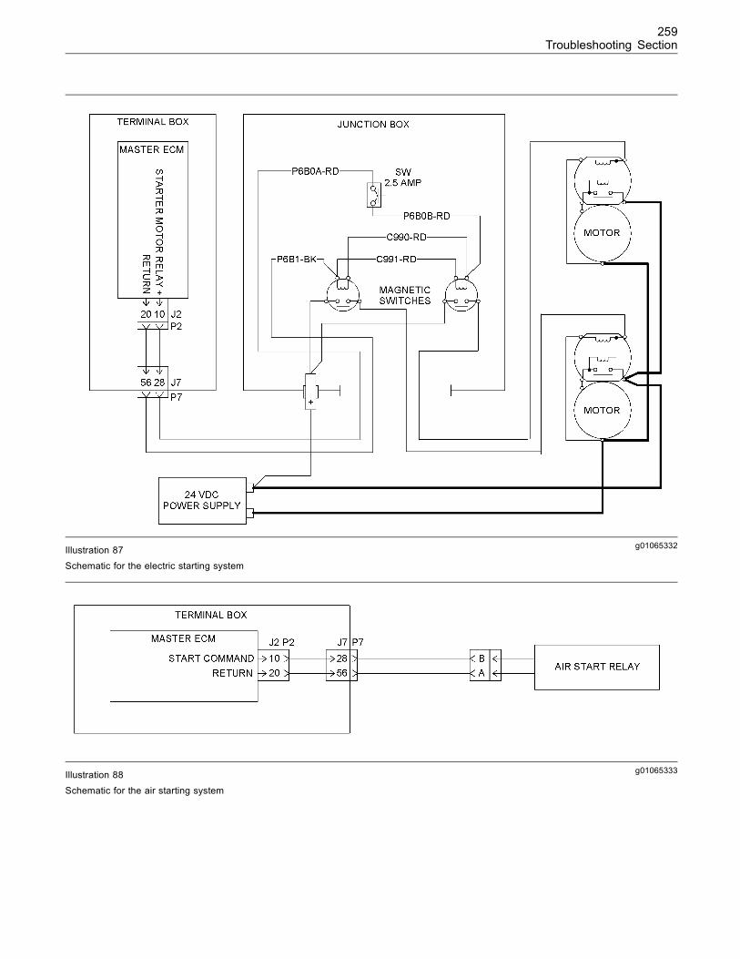
259Troubleshooting Section
g01065332Illustration 87Schematic for the electric starting system
g01065333Illustration 88Schematic for the air starting system
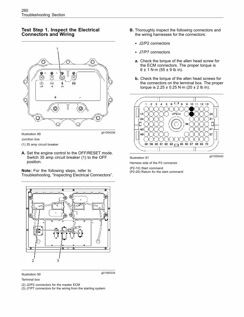
260Troubleshooting Section
Test Step 1. Inspect the ElectricalConnectors and Wiring
g01054206Illustration 89Junction box
(1) 35 amp circuit breaker
A. Set the engine control to the OFF/RESET mode.Switch 35 amp circuit breaker (1) to the OFFposition.
Note: For the following steps, refer toTroubleshooting, “Inspecting Electrical Connectors”.
g01065334Illustration 90
Terminal box
(2) J2/P2 connectors for the master ECM(3) J7/P7 connectors for the wiring from the starting system
B. Thoroughly inspect the following connectors andthe wiring harnesses for the connectors:
• J2/P2 connectors
• J7/P7 connectors
a. Check the torque of the allen head screw forthe ECM connectors. The proper torque is6 ± 1 N·m (55 ± 9 lb in).
b. Check the torque of the allen head screws forthe connectors on the terminal box. The propertorque is 2.25 ± 0.25 N·m (20 ± 2 lb in).
g01055043Illustration 91Harness side of the P2 connector
(P2-10) Start command(P2-20) Return for the start command
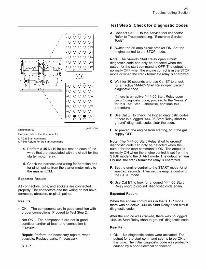
261Troubleshooting Section
g00931050Illustration 92
Harness side of the J7 connector(J7-28) Start command(J7-56) Return for the start command
c. Perform a 45 N (10 lb) pull test on each of thewires that are associated with the circuit for thestarter motor relay.
d. Check the harness and wiring for abrasion andfor pinch points from the starter motor relay tothe master ECM.
Expected Result:
All connectors, pins, and sockets are connectedproperly. The connectors and the wiring do not havecorrosion, abrasion, or pinch points.
Results:
• OK – The components are in good condition withproper connections. Proceed to Test Step 2.
• Not OK – The components are not in goodcondition and/or at least one connection isimproper.
Repair: Perform the necessary repairs, whenpossible. Replace parts, if necessary.
STOP.
Test Step 2. Check for Diagnostic Codes
A. Connect Cat ET to the service tool connector.Refer to Troubleshooting, “Electronic ServiceTools”.
B. Switch the 35 amp circuit breaker ON. Set theengine control to the STOP mode.
Note: The “444-05 Start Relay open circuit”diagnostic code can only be detected when theoutput for the start command is OFF. The output isnormally OFF when the engine control is in the STOPmode or when the crank terminate relay is energized.
C. Wait for 30 seconds and use Cat ET to checkfor an active “444-05 Start Relay open circuit”diagnostic code.
If there is an active “444-05 Start Relay opencircuit” diagnostic code, proceed to the “Results”for this Test Step. Otherwise, continue thisprocedure.
D. Use Cat ET to check the logged diagnostic codes.If there is a logged “444-06 Start Relay short toground” diagnostic code, clear the code.
E. To prevent the engine from starting, shut the gassupply OFF.
Note: The “444-06 Start Relay short to ground”diagnostic code can only be detected when theoutput for the start command is ON. The output isnormally ON when the engine control is set from theSTOP mode to the START mode. The output remainsON until the crank terminate relay is energized.
F. Set the engine control to the START mode for atleast six seconds. Then set the engine control tothe STOP mode.
G. Use Cat ET to look for a logged “444-06 StartRelay short to ground” diagnostic code again.
Expected Result:
When the engine control was in the STOP mode,there was no active “444-05 Start Relay open circuit”diagnostic code.
After the engine was cranked, there was no logged“444-06 Start Relay short to ground” diagnostic code.
Results:
• OK – No diagnostic codes were activated. Theoutput for the start command seems to be OK atthis time. The initial diagnostic code was probablycaused by a poor electrical connection.
262Troubleshooting Section
Repair: If there is an intermittent problemthat is causing the codes to be logged, referto Troubleshooting, “Inspecting ElectricalConnectors”.
STOP.
• Not OK (“444-05 Start Relay open circuit”diagnostic code) – A “444-05 Start Relay opencircuit” diagnostic code was activated. This canbe caused by an actual open circuit or by ashort circuit to the +Battery side. If the engine isequipped with an air starting system, proceedto Test Step 3. If the engine is equipped with anelectric starting system, proceed to Test Step 9.
• Not OK (“444-06 Start Relay short to ground”diagnostic code) – After the engine was cranked,a “444-06 Start Relay short to ground” diagnosticcode was activated. If the engine is equipped withan air starting system, proceed to Test Step 7. Ifthe engine is equipped with an electric startingsystem, proceed to Test Step 10.
Test Step 3. Check for a Short Circuit tothe +Battery Side
Gaseous fuel is present. Personal Injury or Deathcan result from an open flame or spark ignitingthe gaseous fuel causing an explosion and/or fire.Always use a gas detector to determine the pres-ence of gaseous fuel when maintaining and ser-vicing. Contact you local gas provider immediate-ly for assistance in the event of a leak.
Note: Open sparks can be generated during this test.
A. Make sure that no combustible gas is present inthe surrounding atmosphere.
B. Ensure that the engine control is in the STOPmode.
C. Disconnect the connector from the air start relay.Then reconnect the connector. Listen for anaudible click from the relay.
If the ambient noise is too loud, touch the air startrelay when the relay is reconnected in order tofeel the vibration. The relay will vibrate when therelay is de-energized and energized.
Expected Result:
There is no audible click and/or vibration when theair start relay is disconnected and reconnected. Therelay is not energized when the engine control is inthe STOP mode.
Results:
• OK – There is no audible click and/or vibrationwhen the air start relay is disconnected andconnected. There is no short circuit to the +Batteryside. There is an open circuit. Proceed to TestStep 4.
• Not OK – There is an audible click and/or vibrationwhen the air start relay is disconnected andconnected. The relay is receiving power when theengine control is in the STOP mode. Proceed toTest Step 6.
Test Step 4. Create a Short Circuit inorder to Check for an Open Circuit
A. Set the engine control to the OFF/RESET mode.Switch the 35 amp circuit breaker OFF.
B. Disconnect the harness connector from the airstart relay.
C. Install a jumper wire into the two terminals of theharness connector for the air start relay.
D. Switch the 35 amp circuit breaker ON. Set theengine control to the STOP mode.
E. Wait for 30 seconds and use the “ActiveDiagnostic” screen of Cat ET to look for a “444-05Start Relay open circuit” diagnostic code.
Expected Result:
A “444-05 Start Relay open circuit” diagnostic codewas not activated when the jumper wire was installed.
Results:
• OK – A “444-05 Start Relay open circuit” diagnosticcode was not activated when the jumper wire wasinstalled. The master ECM detected the shortcircuit. The harness and the master ECM are OK.There is a problem with the air start relay.
Repair: Perform the following procedure:
1. Set the engine control to the OFF/RESETmode. Switch the 35 amp circuit breaker OFF.
2. Remove the jumper wire from the harnessconnector.
3. Inspect the relay’s connector and the harnessconnector for the relay. Check for damage, formoisture, and for corrosion.
4. Make repairs, as needed.
263Troubleshooting Section
If the problem is not resolved, replace the air startrelay.
STOP.
• Not OK – A “444-05 Start Relay open circuit”diagnostic code was activated when the jumperwire was installed. The master ECM did not detectthe short circuit. Proceed to Test Step 5.
Test Step 5. Check the Master ECM
A. Ensure that the engine control is in theOFF/RESET mode and that the 35 amp circuitbreaker is OFF.
B. Use a 151-6320 Wire Removal Tool to removeterminals P2-10 and P2-20.
C. Install a jumper wire into terminals P2-10 andP2-20. Pull on the jumper wire in order to verifyproper installation.
D. Switch the 35 amp circuit breaker ON. Set theengine control to the STOP mode.
E. Wait for 30 seconds and use the “ActiveDiagnostic” screen of Cat ET to look for an active“444-05 Start Relay open circuit” diagnostic code.
Expected Result:
There is no active “444-05 Start Relay open circuit”diagnostic code.
Results:
• OK – When the jumper wire was installed,there was no active “444-05 Start Relayopen circuit” diagnostic code. The masterECM detects the jumper wire at the P2connector. However, the master ECMdid not detect the jumper wire at the relay’sconnector. There is a problem with the wiring.
The problem could be between the P2 connectorand the J7 connector. Alternatively, the problemcould be in the P7 connector or the wiring that isconnected to the P7 connector.
Repair: Perform the following procedure:
1. Set the engine control to the OFF/RESETmode. Switch the 35 amp circuit breaker OFF.
2. Use a 151-6320Wire Removal Tool to removethe jumper wire from the P2 connector.
3. Reinstall terminals P2-10 and P2-20. Pull onthe wires in order to verify proper installationof the terminals.
4. Repair the harness, when possible. Replace theharness, if necessary.
STOP.
• No – When the jumper wire was installed, a“444-05 Start Relay open circuit” diagnostic codewas activated. The master ECM did not detect thejumper wire. There is a problem with the masterECM.
Repair: Perform the following procedure:
1. Set the engine control to the OFF/RESETmode. Switch the 35 amp circuit breaker OFF.
2. Use a 151-6320 Wire Removal Tool to removethe jumper wire from the P2 connector.
3. Reinstall terminals P2-10 and P2-20. Pull onthe wires in order to verify proper installationof the terminals.
It is unlikely that the master ECM has failed. Exitthis procedure and perform this procedure again. Ifthe problem is not resolved, perform the followingsteps:
Temporarily install a new master ECM. Refer toTroubleshooting, “Replacing the ECM”.
If the problem is resolved with the new ECM,install the original ECM and verify that the problemreturns. If the new ECM operates correctly and theoriginal ECM does not operate correctly, replacethe original ECM. Refer to Troubleshooting,“Replacing the ECM”.
STOP.
Test Step 6. Create an Open Circuit inorder to Check for a Short Circuit
A. Set the engine control to the OFF/RESET mode.Switch the 35 amp circuit breaker OFF.
B. Use a 151-6320 Wire Removal Tool to removeterminals P2-10 and P2-20.
C. Switch the 35 amp circuit breaker ON. Set theengine control to the STOP mode.
D. To prevent the engine from starting, shut OFF themain gas supply.
E. Set the engine control to the START mode for atleast six seconds. Then set the engine control tothe STOP mode.
264Troubleshooting Section
Expected Result:
There is no audible click and/or vibration when therelay is disconnected and reconnected. The relay isnot energized when the engine control is in the STOPmode.
Results:
• OK – When the master ECM was connected, therelay was receiving power. When the master ECMwas not connected, the relay was not receivingpower. There may be a problem with the masterECM.
Repair: Perform the following procedure:
1. Set the engine control to the OFF/RESETmode. Switch the 35 amp circuit breaker OFF.
2. Reinstall terminals P2-10 and P2-20. Pull onthe wires in order to verify proper installationof the terminals.
It is unlikely that the master ECM has failed. Exitthis procedure and perform this procedure again. Ifthe problem is not resolved, perform the followingsteps:
Temporarily install a new master ECM. Refer toTroubleshooting, “Replacing the ECM”.
If the problem is resolved with the new ECM,install the original ECM and verify that the problemreturns. If the new ECM operates correctly and theoriginal ECM does not operate correctly, replacethe original ECM. Refer to Troubleshooting,“Replacing the ECM”.
STOP.
• Not OK – When the master ECM was connected,the relay was receiving power. When the masterECM was not connected, the relay was stillreceiving power. There is a problem with the wiring.
The problem could be between the P2 connectorand the J7 connector. Alternatively, the problemcould be in the P7 connector or the wiring that isconnected to the P7 connector.
Repair: Repair the harness, when possible.Replace the harness, if necessary.
STOP.
Test Step 7. Create an Open Circuit at theAir Start Relay
A. Set the engine control to the OFF/RESET mode.Switch the 35 amp circuit breaker OFF.
B. Disconnect the harness connector from the airstart relay.
C. Switch the 35 amp circuit breaker ON. Set theengine control to the STOP mode.
D. To prevent the engine from starting, shut OFF themain gas supply.
Note: The “444-06 Start Relay short to ground”diagnostic code can only be detected when theoutput for the start command is ON. The output isnormally ON when the engine control is set from theSTOP mode to the START mode. The output remainsON until the crank terminate relay is energized.
E. Set the engine control to the START mode for atleast six seconds. Then set the engine control tothe STOP mode.
F. Use Cat ET to look for a logged “444-06 StartRelay short to ground” diagnostic code again.
Expected Result:
A “444-06 Start Relay short to ground” was notactivated.
Results:
• OK – A “444-06 Start Relay short to ground”diagnostic code was not activated when the airstart relay was disconnected. There is a problemwith the air start relay.
Repair: Perform the following procedure:
1. Set the engine control to the OFF/RESETmode. Switch the 35 amp circuit breaker OFF.
2. Remove the jumper wire from the connector.
3. Inspect the connectors for the air start relay.Check for damage, for moisture, and forcorrosion.
4. Make repairs, as needed.
If the problem is not resolved, replace the air startrelay.
STOP.
• Not OK – A “444-06 Start Relay short to ground”diagnostic code was activated when the air startrelay was disconnected. The air start relay is OK.Proceed to Test Step 8.
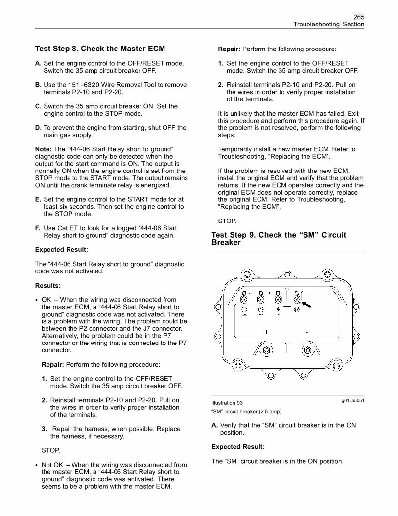
265Troubleshooting Section
Test Step 8. Check the Master ECM
A. Set the engine control to the OFF/RESET mode.Switch the 35 amp circuit breaker OFF.
B. Use the 151-6320Wire Removal Tool to removeterminals P2-10 and P2-20.
C. Switch the 35 amp circuit breaker ON. Set theengine control to the STOP mode.
D. To prevent the engine from starting, shut OFF themain gas supply.
Note: The “444-06 Start Relay short to ground”diagnostic code can only be detected when theoutput for the start command is ON. The output isnormally ON when the engine control is set from theSTOP mode to the START mode. The output remainsON until the crank terminate relay is energized.
E. Set the engine control to the START mode for atleast six seconds. Then set the engine control tothe STOP mode.
F. Use Cat ET to look for a logged “444-06 StartRelay short to ground” diagnostic code again.
Expected Result:
The “444-06 Start Relay short to ground” diagnosticcode was not activated.
Results:
• OK – When the wiring was disconnected fromthe master ECM, a “444-06 Start Relay short toground” diagnostic code was not activated. Thereis a problem with the wiring. The problem could bebetween the P2 connector and the J7 connector.Alternatively, the problem could be in the P7connector or the wiring that is connected to the P7connector.
Repair: Perform the following procedure:
1. Set the engine control to the OFF/RESETmode. Switch the 35 amp circuit breaker OFF.
2. Reinstall terminals P2-10 and P2-20. Pull onthe wires in order to verify proper installationof the terminals.
3. Repair the harness, when possible. Replacethe harness, if necessary.
STOP.
• Not OK – When the wiring was disconnected fromthe master ECM, a “444-06 Start Relay short toground” diagnostic code was activated. Thereseems to be a problem with the master ECM.
Repair: Perform the following procedure:
1. Set the engine control to the OFF/RESETmode. Switch the 35 amp circuit breaker OFF.
2. Reinstall terminals P2-10 and P2-20. Pull onthe wires in order to verify proper installationof the terminals.
It is unlikely that the master ECM has failed. Exitthis procedure and perform this procedure again. Ifthe problem is not resolved, perform the followingsteps:
Temporarily install a new master ECM. Refer toTroubleshooting, “Replacing the ECM”.
If the problem is resolved with the new ECM,install the original ECM and verify that the problemreturns. If the new ECM operates correctly and theoriginal ECM does not operate correctly, replacethe original ECM. Refer to Troubleshooting,“Replacing the ECM”.
STOP.
Test Step 9. Check the “SM” CircuitBreaker
g01055051Illustration 93
“SM” circuit breaker (2.5 amp)
A. Verify that the “SM” circuit breaker is in the ONposition.
Expected Result:
The “SM” circuit breaker is in the ON position.
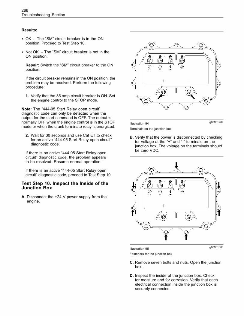
266Troubleshooting Section
Results:
• OK – The “SM” circuit breaker is in the ONposition. Proceed to Test Step 10.
• Not OK – The “SM” circuit breaker is not in theON position.
Repair: Switch the “SM” circuit breaker to the ONposition.
If the circuit breaker remains in the ON position, theproblem may be resolved. Perform the followingprocedure:
1. Verify that the 35 amp circuit breaker is ON. Setthe engine control to the STOP mode.
Note: The “444-05 Start Relay open circuit”diagnostic code can only be detected when theoutput for the start command is OFF. The output isnormally OFF when the engine control is in the STOPmode or when the crank terminate relay is energized.
2. Wait for 30 seconds and use Cat ET to checkfor an active “444-05 Start Relay open circuit”diagnostic code.
If there is no active “444-05 Start Relay opencircuit” diagnostic code, the problem appearsto be resolved. Resume normal operation.
If there is an active “444-05 Start Relay opencircuit” diagnostic code, proceed to Test Step 10.
Test Step 10. Inspect the Inside of theJunction Box
A. Disconnect the +24 V power supply from theengine.
g00931289Illustration 94
Terminals on the junction box
B. Verify that the power is disconnected by checkingfor voltage at the “+” and “-” terminals on thejunction box. The voltage on the terminals shouldbe zero VDC.
g00931303Illustration 95Fasteners for the junction box
C. Remove seven bolts and nuts. Open the junctionbox.
D. Inspect the inside of the junction box. Checkfor moisture and for corrosion. Verify that eachelectrical connection inside the junction box issecurely connected.
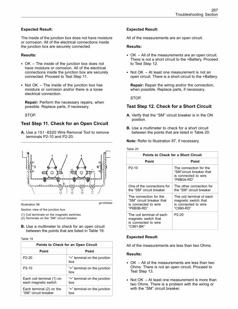
267Troubleshooting Section
Expected Result:
The inside of the junction box does not have moistureor corrosion. All of the electrical connections insidethe junction box are securely connected.
Results:
• OK – The inside of the junction box does nothave moisture or corrosion. All of the electricalconnections inside the junction box are securelyconnected. Proceed to Test Step 11.
• Not OK – The inside of the junction box hasmoisture or corrosion and/or there is a looseelectrical connection.
Repair: Perform the necessary repairs, whenpossible. Replace parts, if necessary.
STOP.
Test Step 11. Check for an Open Circuit
A. Use a 151-6320 Wire Removal Tool to removeterminals P2-10 and P2-20.
g01055064Illustration 96
Section view of the junction box(1) Coil terminals on the magnetic switches(2) Terminals on the “SM” circuit breaker
B. Use a multimeter to check for an open circuitbetween the points that are listed in Table 19:
Table 19
Points to Check for an Open Circuit
Point Point
P2-20 “+” terminal on the junctionbox
P2-10 “+” terminal on the junctionbox
Each coil terminal (1) oneach magnetic switch
“+” terminal on the junctionbox
Each terminal (2) on the“SM” circuit breaker
“+” terminal on the junctionbox
Expected Result:
All of the measurements are an open circuit.
Results:
• OK – All of the measurements are an open circuit.There is not a short circuit to the +Battery. Proceedto Test Step 12.
• Not OK – At least one measurement is not anopen circuit. There is a short circuit to the +Battery.
Repair: Repair the wiring and/or the connection,when possible. Replace parts, if necessary.
STOP.
Test Step 12. Check for a Short Circuit
A. Verify that the “SM” circuit breaker is in the ONposition.
B. Use a multimeter to check for a short circuitbetween the points that are listed in Table 20:
Note: Refer to Illustration 87, if necessary.
Table 20
Points to Check for a Short Circuit
Point Point
P2-10 The connection for the“SM”circuit breaker thatis connected to wire“P6B0A-RD”
One of the connections forthe “SM” circuit breaker
The other connection forthe “SM” circuit breaker
The connection for the“SM” circuit breaker thatis connected to wire“P6B0B-RD”
The coil terminal of eachmagnetic switch thatis connected to wire“C990-RD”
The coil terminal of eachmagnetic switch thatis connected to wire“C991-BK”
P2-20
Expected Result:
All of the measurements are less than two Ohms.
Results:
• OK – All of the measurements are less than twoOhms. There is not an open circuit. Proceed toTest Step 13.
• Not OK – At least one measurement is more thantwo Ohms. There is a problem with the wiring orwith the “SM” circuit breaker.
268Troubleshooting Section
Repair: Repair the wiring and/or the connection,when possible. Replace parts, if necessary.
STOP.
Test Step 13. Check the Coils for theMagnetic Switches
A. Use a multimeter to measure the resistance of thecoil for each magnetic switch.
Expected Result:
The resistance of each coil is between 16 and 20Ohms.
Results:
• OK – The resistance of each coil is between 16Ohms and 20 Ohms. The coil resistance for eachmagnetic switch is correct.
Repair:
1. Install the seven bolts and nuts for the junctionbox.
2. Reconnect the +24 V power supply to theengine.
Proceed to Test Step 14.
• Not OK – The resistance of a coil is not between16 Ohms and 20 Ohms. The resistance of a coil fora magnetic switch is incorrect.
Repair: Replace the magnetic switch. Verify thatthe original problem is resolved.
STOP.
Test Step 14. Check the Operation of theMaster ECM
A. Verify that terminals P2-10 and P2-20 are removedfrom the P2 connector.
B. Verify that the 35 amp circuit breaker is ON. Verifythat the “SM” circuit breaker is ON.
Note: The “444-05 Start Relay open circuit”diagnostic code can only be detected when theoutput for the start command is OFF. The output isnormally OFF when the engine control is in the STOPmode or when the crank terminate relay is energized.
C. Set the engine control to the STOP mode.
A “444-05 Start Relay open circuit” diagnosticcode should not be activated.
D. Set the engine control to the OFF/RESET mode.Switch the 35 amp circuit breaker OFF.
E. Reinstall terminals P2-10 and P2-20. Pull on thewires in order to verify proper installation of theterminals.
F. Switch the 35 amp circuit breaker ON.
Note: The “444-06 Start Relay short to ground”diagnostic code can only be detected when theoutput for the start command is ON. The output isnormally ON when the engine control is set from theSTOP mode to the START mode. The output remainsON until the crank terminate relay is energized.
G. Set the engine control to the START mode.Look for a “444-06 Start Relay short to ground”diagnostic code.
A “444-06 Start Relay short to ground” diagnosticcode should not be activated.
Expected Result:
No diagnostic codes were activated.
Results:
• OK – No diagnostic codes were activated. Theinitial diagnostic code was probably caused by apoor electrical connection.
Repair: If there is an intermittent problemthat is causing the codes to be logged, referto Troubleshooting, “Inspecting ElectricalConnectors”.
STOP.
• Not OK – A diagnostic code was activated. Theremay be a problem with the master ECM.
Repair: It is unlikely that the master ECM hasfailed. Exit this procedure and perform thisprocedure again. If the problem is not resolved,perform the following steps:
Temporarily install a new master ECM. Refer toTroubleshooting, “Replacing the ECM”.
If the problem is resolved with the new ECM,install the original ECM and verify that the problemreturns. If the new ECM operates correctly and theoriginal ECM does not operate correctly, replacethe original ECM. Refer to Troubleshooting,“Replacing the ECM”.
STOP.
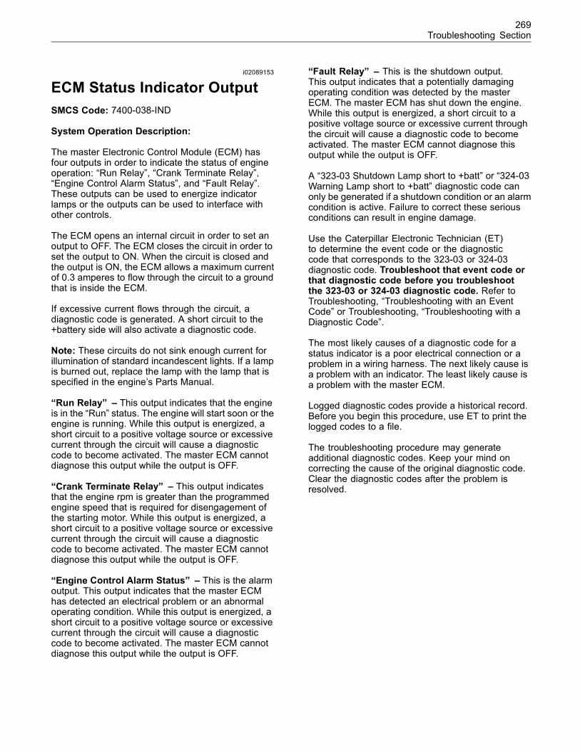
269Troubleshooting Section
i02089153
ECM Status Indicator OutputSMCS Code: 7400-038-IND
System Operation Description:
The master Electronic Control Module (ECM) hasfour outputs in order to indicate the status of engineoperation: “Run Relay”, “Crank Terminate Relay”,“Engine Control Alarm Status”, and “Fault Relay”.These outputs can be used to energize indicatorlamps or the outputs can be used to interface withother controls.
The ECM opens an internal circuit in order to set anoutput to OFF. The ECM closes the circuit in order toset the output to ON. When the circuit is closed andthe output is ON, the ECM allows a maximum currentof 0.3 amperes to flow through the circuit to a groundthat is inside the ECM.
If excessive current flows through the circuit, adiagnostic code is generated. A short circuit to the+battery side will also activate a diagnostic code.
Note: These circuits do not sink enough current forillumination of standard incandescent lights. If a lampis burned out, replace the lamp with the lamp that isspecified in the engine’s Parts Manual.
“Run Relay” – This output indicates that the engineis in the “Run” status. The engine will start soon or theengine is running. While this output is energized, ashort circuit to a positive voltage source or excessivecurrent through the circuit will cause a diagnosticcode to become activated. The master ECM cannotdiagnose this output while the output is OFF.
“Crank Terminate Relay” – This output indicatesthat the engine rpm is greater than the programmedengine speed that is required for disengagement ofthe starting motor. While this output is energized, ashort circuit to a positive voltage source or excessivecurrent through the circuit will cause a diagnosticcode to become activated. The master ECM cannotdiagnose this output while the output is OFF.
“Engine Control Alarm Status” – This is the alarmoutput. This output indicates that the master ECMhas detected an electrical problem or an abnormaloperating condition. While this output is energized, ashort circuit to a positive voltage source or excessivecurrent through the circuit will cause a diagnosticcode to become activated. The master ECM cannotdiagnose this output while the output is OFF.
“Fault Relay” – This is the shutdown output.This output indicates that a potentially damagingoperating condition was detected by the masterECM. The master ECM has shut down the engine.While this output is energized, a short circuit to apositive voltage source or excessive current throughthe circuit will cause a diagnostic code to becomeactivated. The master ECM cannot diagnose thisoutput while the output is OFF.
A “323-03 Shutdown Lamp short to +batt” or “324-03Warning Lamp short to +batt” diagnostic code canonly be generated if a shutdown condition or an alarmcondition is active. Failure to correct these seriousconditions can result in engine damage.
Use the Caterpillar Electronic Technician (ET)to determine the event code or the diagnosticcode that corresponds to the 323-03 or 324-03diagnostic code. Troubleshoot that event code orthat diagnostic code before you troubleshootthe 323-03 or 324-03 diagnostic code. Refer toTroubleshooting, “Troubleshooting with an EventCode” or Troubleshooting, “Troubleshooting with aDiagnostic Code”.
The most likely causes of a diagnostic code for astatus indicator is a poor electrical connection or aproblem in a wiring harness. The next likely cause isa problem with an indicator. The least likely cause isa problem with the master ECM.
Logged diagnostic codes provide a historical record.Before you begin this procedure, use ET to print thelogged codes to a file.
The troubleshooting procedure may generateadditional diagnostic codes. Keep your mind oncorrecting the cause of the original diagnostic code.Clear the diagnostic codes after the problem isresolved.
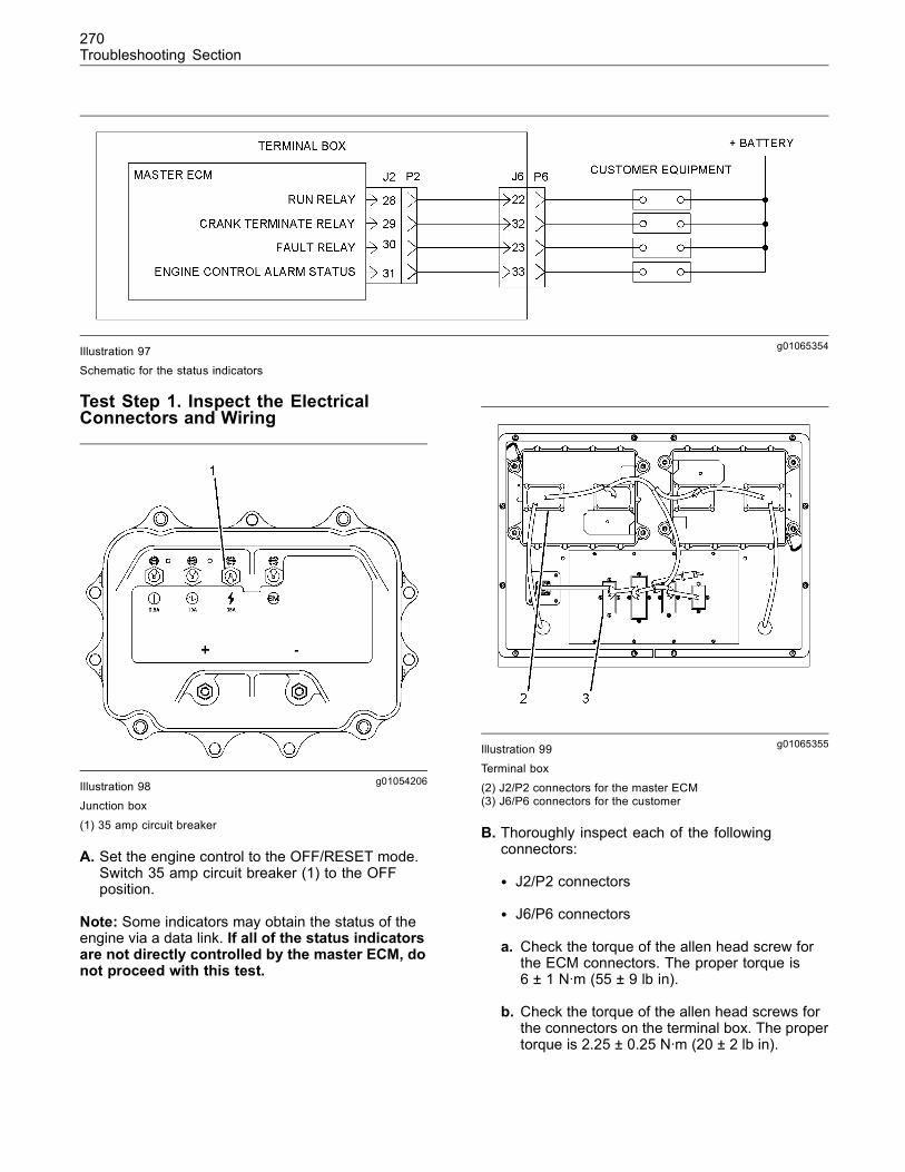
270Troubleshooting Section
g01065354Illustration 97Schematic for the status indicators
Test Step 1. Inspect the ElectricalConnectors and Wiring
g01054206Illustration 98Junction box
(1) 35 amp circuit breaker
A. Set the engine control to the OFF/RESET mode.Switch 35 amp circuit breaker (1) to the OFFposition.
Note: Some indicators may obtain the status of theengine via a data link. If all of the status indicatorsare not directly controlled by the master ECM, donot proceed with this test.
g01065355Illustration 99Terminal box
(2) J2/P2 connectors for the master ECM(3) J6/P6 connectors for the customer
B. Thoroughly inspect each of the followingconnectors:
• J2/P2 connectors
• J6/P6 connectors
a. Check the torque of the allen head screw forthe ECM connectors. The proper torque is6 ± 1 N·m (55 ± 9 lb in).
b. Check the torque of the allen head screws forthe connectors on the terminal box. The propertorque is 2.25 ± 0.25 N·m (20 ± 2 lb in).
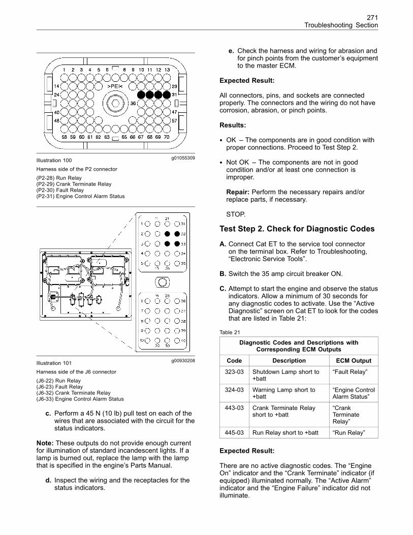
271Troubleshooting Section
g01055309Illustration 100Harness side of the P2 connector
(P2-28) Run Relay(P2-29) Crank Terminate Relay(P2-30) Fault Relay(P2-31) Engine Control Alarm Status
g00930208Illustration 101Harness side of the J6 connector
(J6-22) Run Relay(J6-23) Fault Relay(J6-32) Crank Terminate Relay(J6-33) Engine Control Alarm Status
c. Perform a 45 N (10 lb) pull test on each of thewires that are associated with the circuit for thestatus indicators.
Note: These outputs do not provide enough currentfor illumination of standard incandescent lights. If alamp is burned out, replace the lamp with the lampthat is specified in the engine’s Parts Manual.
d. Inspect the wiring and the receptacles for thestatus indicators.
e. Check the harness and wiring for abrasion andfor pinch points from the customer’s equipmentto the master ECM.
Expected Result:
All connectors, pins, and sockets are connectedproperly. The connectors and the wiring do not havecorrosion, abrasion, or pinch points.
Results:
• OK – The components are in good condition withproper connections. Proceed to Test Step 2.
• Not OK – The components are not in goodcondition and/or at least one connection isimproper.
Repair: Perform the necessary repairs and/orreplace parts, if necessary.
STOP.
Test Step 2. Check for Diagnostic Codes
A. Connect Cat ET to the service tool connectoron the terminal box. Refer to Troubleshooting,“Electronic Service Tools”.
B. Switch the 35 amp circuit breaker ON.
C. Attempt to start the engine and observe the statusindicators. Allow a minimum of 30 seconds forany diagnostic codes to activate. Use the “ActiveDiagnostic” screen on Cat ET to look for the codesthat are listed in Table 21:
Table 21
Diagnostic Codes and Descriptions withCorresponding ECM Outputs
Code Description ECM Output
323-03 Shutdown Lamp short to+batt
“Fault Relay”
324-03 Warning Lamp short to+batt
“Engine ControlAlarm Status”
443-03 Crank Terminate Relayshort to +batt
“CrankTerminateRelay”
445-03 Run Relay short to +batt “Run Relay”
Expected Result:
There are no active diagnostic codes. The “EngineOn” indicator and the “Crank Terminate” indicator (ifequipped) illuminated normally. The “Active Alarm”indicator and the “Engine Failure” indicator did notilluminate.
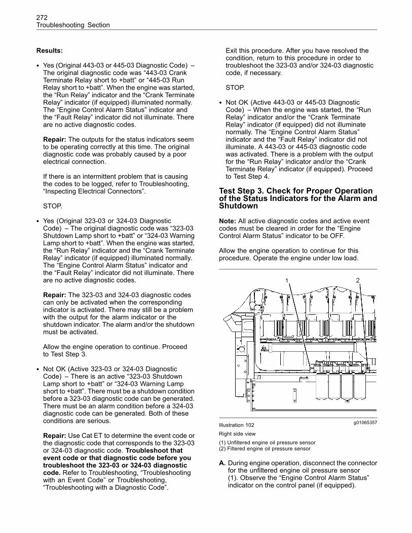
272Troubleshooting Section
Results:
• Yes (Original 443-03 or 445-03 Diagnostic Code) –The original diagnostic code was “443-03 CrankTerminate Relay short to +batt” or “445-03 RunRelay short to +batt”. When the engine was started,the “Run Relay” indicator and the “Crank TerminateRelay” indicator (if equipped) illuminated normally.The “Engine Control Alarm Status” indicator andthe “Fault Relay” indicator did not illuminate. Thereare no active diagnostic codes.
Repair: The outputs for the status indicators seemto be operating correctly at this time. The originaldiagnostic code was probably caused by a poorelectrical connection.
If there is an intermittent problem that is causingthe codes to be logged, refer to Troubleshooting,“Inspecting Electrical Connectors”.
STOP.
• Yes (Original 323-03 or 324-03 DiagnosticCode) – The original diagnostic code was “323-03Shutdown Lamp short to +batt” or “324-03 WarningLamp short to +batt”. When the engine was started,the “Run Relay” indicator and the “Crank TerminateRelay” indicator (if equipped) illuminated normally.The “Engine Control Alarm Status” indicator andthe “Fault Relay” indicator did not illuminate. Thereare no active diagnostic codes.
Repair: The 323-03 and 324-03 diagnostic codescan only be activated when the correspondingindicator is activated. There may still be a problemwith the output for the alarm indicator or theshutdown indicator. The alarm and/or the shutdownmust be activated.
Allow the engine operation to continue. Proceedto Test Step 3.
• Not OK (Active 323-03 or 324-03 DiagnosticCode) – There is an active “323-03 ShutdownLamp short to +batt” or “324-03 Warning Lampshort to +batt”. There must be a shutdown conditionbefore a 323-03 diagnostic code can be generated.There must be an alarm condition before a 324-03diagnostic code can be generated. Both of theseconditions are serious.
Repair: Use Cat ET to determine the event code orthe diagnostic code that corresponds to the 323-03or 324-03 diagnostic code. Troubleshoot thatevent code or that diagnostic code before youtroubleshoot the 323-03 or 324-03 diagnosticcode. Refer to Troubleshooting, “Troubleshootingwith an Event Code” or Troubleshooting,“Troubleshooting with a Diagnostic Code”.
Exit this procedure. After you have resolved thecondition, return to this procedure in order totroubleshoot the 323-03 and/or 324-03 diagnosticcode, if necessary.
STOP.
• Not OK (Active 443-03 or 445-03 DiagnosticCode) – When the engine was started, the “RunRelay” indicator and/or the “Crank TerminateRelay” indicator (if equipped) did not illuminatenormally. The “Engine Control Alarm Status”indicator and the “Fault Relay” indicator did notilluminate. A 443-03 or 445-03 diagnostic codewas activated. There is a problem with the outputfor the “Run Relay” indicator and/or the “CrankTerminate Relay” indicator (if equipped). Proceedto Test Step 4.
Test Step 3. Check for Proper Operationof the Status Indicators for the Alarm andShutdown
Note: All active diagnostic codes and active eventcodes must be cleared in order for the “EngineControl Alarm Status” indicator to be OFF.
Allow the engine operation to continue for thisprocedure. Operate the engine under low load.
g01065357Illustration 102Right side view(1) Unfiltered engine oil pressure sensor(2) Filtered engine oil pressure sensor
A. During engine operation, disconnect the connectorfor the unfiltered engine oil pressure sensor(1). Observe the “Engine Control Alarm Status”indicator on the control panel (if equipped).
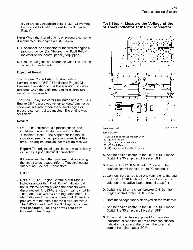
273Troubleshooting Section
If you are only troubleshooting a “324-03 WarningLamp short to +batt”, proceed to the “ExpectedResult”.
Note:When the filtered engine oil pressure sensor isdisconnected, the engine will shut down.
B. Disconnect the connector for the filtered engine oilpressure sensor (2). Observe the “Fault Relay”indicator on the control panel (if equipped).
C. Use the “Diagnostics” screen on Cat ET to look foractive diagnostic codes.
Expected Result:
The “Engine Control Alarm Status” indicatorilluminated and a “542-03 Unfiltered Engine OilPressure open/short to +batt” diagnostic code wasactivated when the unfiltered engine oil pressuresensor is disconnected.
The “Fault Relay” indicator illuminated and a “100-03Engine Oil Pressure open/short to +batt” diagnosticcode was activated when the filtered engine oilpressure sensor is disconnected. The engine wasshut down.
Results:
• OK – The indicators, diagnostic codes, andshutdown were activated according to the“Expected Result”. The outputs for the statusindicators seem to be operating correctly at thistime. The original problem seems to be resolved.
Repair: The original diagnostic code was probablycaused by a poor electrical connection.
If there is an intermittent problem that is causingthe codes to be logged, refer to Troubleshooting,“Inspecting Electrical Connectors”.
STOP.
• Not OK – The “Engine Control Alarm Status”indicator and/or the “Fault Relay” indicator didnot illuminate normally when the sensors weredisconnected. A “323-03 Shutdown Lamp short to+batt” and/or a “324-03 Warning Lamp short to+batt” diagnostic code was generated. There is aproblem with the output for the status indicators.The “542-03” and the “100-03” diagnostic codeswere generated. The engine was shut down.Proceed to Test Step 4.
Test Step 4. Measure the Voltage of theSuspect Indicator at the P2 Connector
g00930238Illustration 103
Terminal box(1) Ground strap for the master ECM(P2-28) Run Relay(P2-29) Crank Terminate Relay(P2-30) Fault Relay(P2-31) Engine Control Alarm Status
A. Set the engine control to the OFF/RESET mode.Switch the 35 amp circuit breaker OFF.
B. Insert a 7X-1710 Multimeter Probe into thesuspect control terminal in the P2 connector.
C. Connect the positive lead of a voltmeter to the endof the 7X-1710 Multimeter Probe. Connect thevoltmeter’s negative lead to ground strap (1).
D. Switch the 35 amp circuit breaker ON. Set theengine control to the STOP mode.
E. Note the voltage that is displayed on the voltmeter.
F. Set the engine control to the OFF/RESET mode.Switch the 35 amp circuit breaker OFF.
G. If the customer has equipment for the statusindicators, disconnect one wire from the suspectindicator. Be sure to disconnect the wire thatcomes from the master ECM.
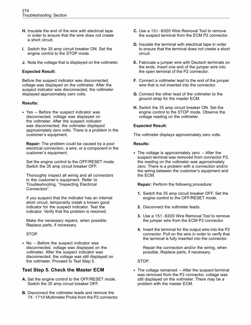
274Troubleshooting Section
H. Insulate the end of the wire with electrical tapein order to ensure that the wire does not createa short circuit.
I. Switch the 35 amp circuit breaker ON. Set theengine control to the STOP mode.
J. Note the voltage that is displayed on the voltmeter.
Expected Result:
Before the suspect indicator was disconnected,voltage was displayed on the voltmeter. After thesuspect indicator was disconnected, the voltmeterdisplayed approximately zero volts.
Results:
• Yes – Before the suspect indicator wasdisconnected, voltage was displayed onthe voltmeter. After the suspect indicatorwas disconnected, the voltmeter displayedapproximately zero volts. There is a problem in thecustomer’s equipment.
Repair: The problem could be caused by a poorelectrical connection, a wire, or a component in thecustomer’s equipment.
Set the engine control to the OFF/RESET mode.Switch the 35 amp circuit breaker OFF.
Thoroughly inspect all wiring and all connectorsin the customer’s equipment. Refer toTroubleshooting, “Inspecting ElectricalConnectors”.
If you suspect that the indicator has an internalshort circuit, temporarily install a known goodindicator for the suspect indicator. Test theindicator. Verify that the problem is resolved.
Make the necessary repairs, when possible.Replace parts, if necessary.
STOP.
• No – Before the suspect indicator wasdisconnected, voltage was displayed on thevoltmeter. After the suspect indicator wasdisconnected, the voltage was still displayed onthe voltmeter. Proceed to Test Step 5.
Test Step 5. Check the Master ECM
A. Set the engine control to the OFF/RESET mode.Switch the 35 amp circuit breaker OFF.
B. Disconnect the voltmeter leads and remove the7X-1710Multimeter Probe from the P2 connector.
C. Use a 151-6320 Wire Removal Tool to removethe suspect terminal from the ECM P2 connector.
D. Insulate the terminal with electrical tape in orderto ensure that the terminal does not create a shortcircuit.
E. Fabricate a jumper wire with Deutsch terminals onthe ends. Insert one end of the jumper wire intothe open terminal of the P2 connector.
F. Connect a voltmeter lead to the end of the jumperwire that is not inserted into the connector.
G. Connect the other lead of the voltmeter to theground strap for the master ECM.
H. Switch the 35 amp circuit breaker ON. Set theengine control to the STOP mode. Observe thevoltage reading on the voltmeter.
Expected Result:
The voltmeter displays approximately zero volts.
Results:
• The voltage is approximately zero – After thesuspect terminal was removed from connector P2,the reading on the voltmeter was approximatelyzero. There is a problem with a connection and/orthe wiring between the customer’s equipment andthe ECM.
Repair: Perform the following procedure:
1. Switch the 35 amp circuit breaker OFF. Set theengine control to the OFF/RESET mode.
2. Disconnect the voltmeter leads.
3. Use a 151-6320 Wire Removal Tool to removethe jumper wire from the ECM P2 connector.
4. Insert the terminal for the output wire into the P2connector. Pull on the wire in order to verify thatthe terminal is fully inserted into the connector.
Repair the connection and/or the wiring, whenpossible. Replace parts, if necessary.
STOP.
• The voltage remained – After the suspect terminalwas removed from the P2 connector, voltage wasstill displayed on the voltmeter. There may be aproblem with the master ECM.
275Troubleshooting Section
Repair: It is unlikely that the master ECM hasfailed. Exit this procedure and perform thisprocedure again. If the problem is not resolved,perform the following steps:
Temporarily install a new master ECM. Refer toTroubleshooting, “Replacing the ECM”.
If the problem is resolved with the new ECM,install the original ECM and verify that the problemreturns. If the new ECM operates correctly and theoriginal ECM does not operate correctly, replacethe original ECM. Refer to Troubleshooting,“Replacing the ECM”.
STOP.
i02089172
Electrical Power SupplySMCS Code: 1408-038
System Operation Description:
Electrical power is supplied to the followingcomponents:
• Master Electronic Control Module (ECM)
• Slave ECM
• Integrated Temperature Sensing Module (ITSM)
• Fuel metering valve
• Actuator for the throttle
• Actuator for the compressor bypass group
The cause of an intermittent power supply can occuron either the positive side or the negative side of thepower supply.
The 24 VDC power supply for the engine can beprovided by a battery or by an electrical powersupply. If the power is provided by an electrical powersupply, the maximum allowable AC ripple is 150 mVAC peak to peak. The minimum requirement for thepower supply is 22 VDC at 30 amperes. The wiringfrom the power supply to the ECM must provide amaximum voltage drop of 1.0 VDC.
The master ECM input at terminal 70 of the P1connector (“Switched +Battery”) receives batteryvoltage from the engine control when the control is inthe START mode, in the STOP mode, or in the AUTOmode. When the master ECM detects battery voltageat this input, the master ECM will power up. Whenbattery voltage is removed from this input, the masterECM will power down after the engine has shut down.
For the slave ECM, the input at terminal 70 of theP3 connector (“Switched +Battery”) receives batteryvoltage from the engine control when the control is inthe START mode, in the STOP mode, or in the AUTOmode. When the slave ECM detects battery voltageat this input, the slave ECM will power up.
The “168-02” diagnostic code indicates that thevoltage of the power supply is intermittent or lowwhile the engine is running. If the supply voltagedrops to zero and stays at zero, neither ECM will logthis code. The engine will shut down.
The “336-02” diagnostic code indicates that themaster ECM has detected a problem with the circuitfor the engine control.
Logged diagnostic codes provide a historical record.Before you begin this procedure, use the CaterpillarElectronic Technician (ET) to print the logged codesto a file.
This procedure may generate additional diagnosticcodes. Keep your mind on correcting the cause of theoriginal diagnostic code. Clear the diagnostic codesafter the problem is resolved.
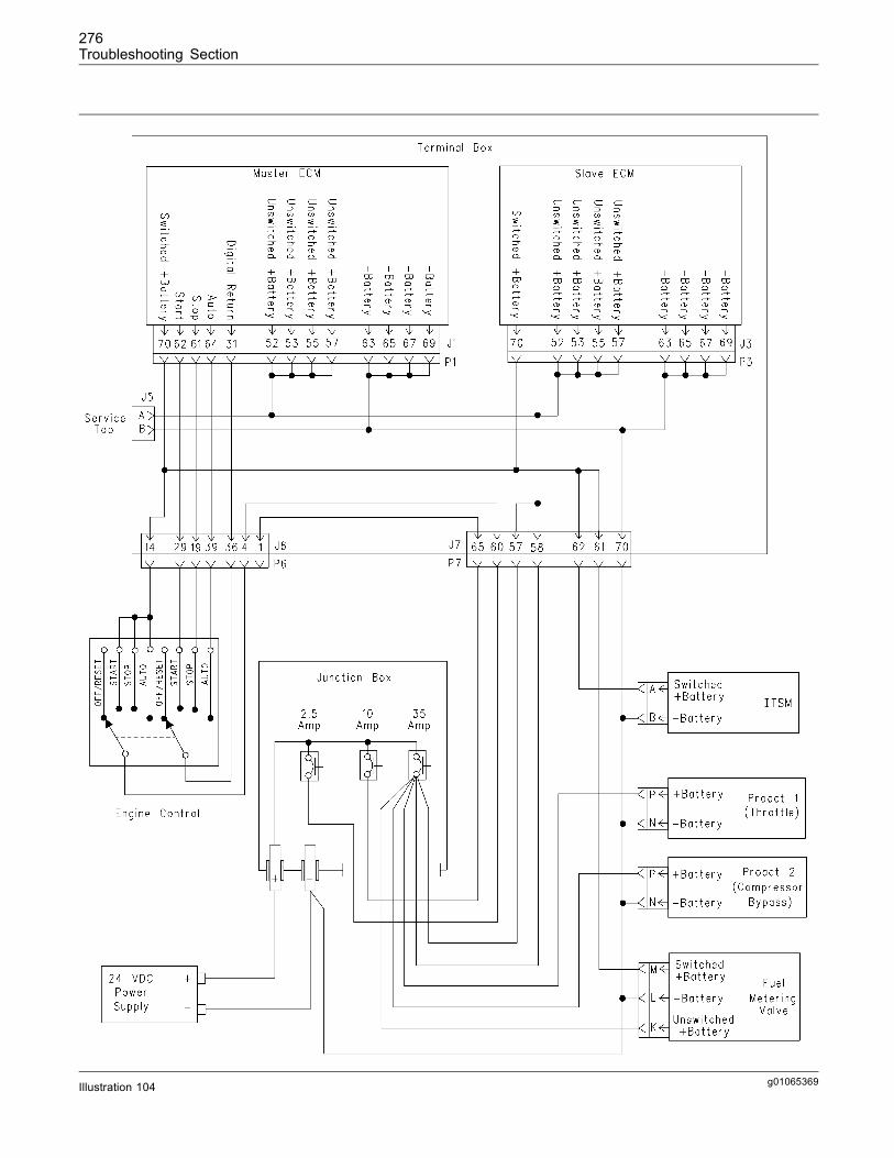
276Troubleshooting Section
g01065369Illustration 104

277Troubleshooting Section
Schematic for the electrical power
Test Step 1. Inspect the ElectricalConnectors and Wiring
g01055400Illustration 105
Junction box(1) Circuit breaker for the engine control (2.5 ampere)(2) Circuit breaker for the customer (10 ampere)(3) Circuit breaker for the engine (35 ampere)(4) Circuit breaker for the master ECM output for the electrical
starting motor (2.5 ampere)
A. Set the engine control to the OFF/RESET mode.Switch 35 amp circuit breaker (3) to the OFFposition.
Note: For the following steps, refer toTroubleshooting, “Inspecting Electrical Connectors”.
g01065370Illustration 106Terminal box(5) J5 connector for the service tool(6) J1/P1 connectors for the master ECM(7) J6/P6 connectors for the customer(8) J7/P7 connectors for the harness for electrical power(9) J3/P3 connectors for the slave ECM
B. Thoroughly inspect each of the followingconnectors:
• J1/P1 connectors
• J3/P3 connectors
• J5, J6/P6 and J7/P7 connectors
• Connectors for the 24 VDC power supply
• Connectors for the engine control
a. Check the torque of the allen head screw forthe ECM connectors. The proper torque is6 ± 1 N·m (55 ± 9 lb in).
b. Check the torque of the allen head screws forthe connectors on the terminal box. The propertorque is 2.25 ± 0.25 N·m (20 ± 2 lb in).
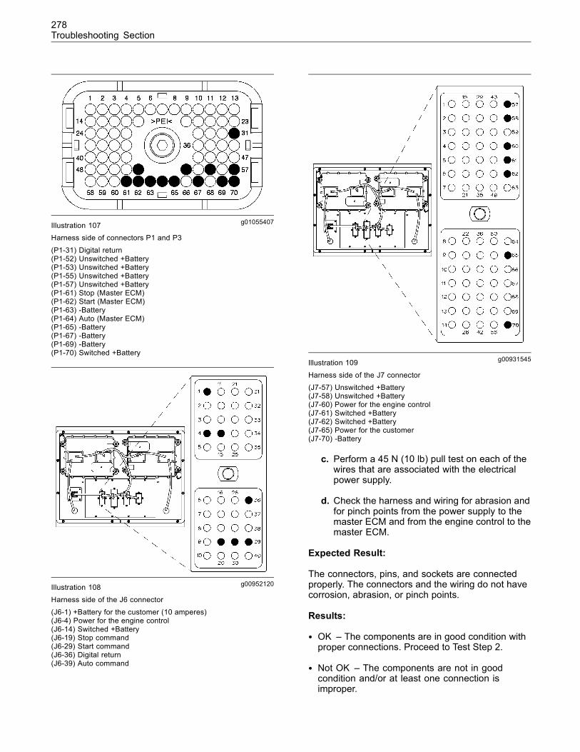
278Troubleshooting Section
g01055407Illustration 107Harness side of connectors P1 and P3
(P1-31) Digital return(P1-52) Unswitched +Battery(P1-53) Unswitched +Battery(P1-55) Unswitched +Battery(P1-57) Unswitched +Battery(P1-61) Stop (Master ECM)(P1-62) Start (Master ECM)(P1-63) -Battery(P1-64) Auto (Master ECM)(P1-65) -Battery(P1-67) -Battery(P1-69) -Battery(P1-70) Switched +Battery
g00952120Illustration 108Harness side of the J6 connector
(J6-1) +Battery for the customer (10 amperes)(J6-4) Power for the engine control(J6-14) Switched +Battery(J6-19) Stop command(J6-29) Start command(J6-36) Digital return(J6-39) Auto command
g00931545Illustration 109
Harness side of the J7 connector(J7-57) Unswitched +Battery(J7-58) Unswitched +Battery(J7-60) Power for the engine control(J7-61) Switched +Battery(J7-62) Switched +Battery(J7-65) Power for the customer(J7-70) -Battery
c. Perform a 45 N (10 lb) pull test on each of thewires that are associated with the electricalpower supply.
d. Check the harness and wiring for abrasion andfor pinch points from the power supply to themaster ECM and from the engine control to themaster ECM.
Expected Result:
The connectors, pins, and sockets are connectedproperly. The connectors and the wiring do not havecorrosion, abrasion, or pinch points.
Results:
• OK – The components are in good condition withproper connections. Proceed to Test Step 2.
• Not OK – The components are not in goodcondition and/or at least one connection isimproper.
279Troubleshooting Section
Repair: Perform the necessary repairs and/orreplace parts, if necessary. Ensure that all of theseals are properly installed. Make sure that theconnectors are properly fastened. Verify that therepair has eliminated the problem.
STOP.
Test Step 2. Check the Voltage at thePower Supply, at the Master ECM, and atthe Slave ECM
A. Make sure that the engine will not crank duringthis procedure. For an engine with an electricstarting motor, make sure that the battery cablesare disconnected from the motor. For an enginewith an air starting motor, make sure that thepressurized air supply is OFF. Make sure that theair is purged from the system.
Note: If a power supply is used instead of batteries,the minimum voltage for the power supply is 22 VDC.Troubleshoot the power supply if the voltage is lessthan 22 VDC or more than 29 VDC.
B. Measure the voltage at the terminals for the powersupply. Record the measurement.
C. Insert two 7X-1710 Multimeter Probes into theharness side of the P1 connector. Insert the firstprobe into terminal 52. Insert the second probeinto terminal 63. Connect a multimeter to theprobes.
D. Switch the 35 amp circuit breaker ON.
E. Measure the power supply voltage at the P1connector. During the measurement, wiggle theharness in order to check for an intermittentproblem. Be sure to wiggle the harness near eachof the connections. Record the measurement.
F. Switch the 35 amp circuit breaker OFF. Removethe probes from the P1 connector.
G. Insert two 7X-1710 Multimeter Probes into theharness side of the P3 connector. Insert the firstprobe into terminal 52. Insert the second probeinto terminal 63. Connect a multimeter to theprobes.
H. Switch the 35 amp circuit breaker ON.
I. Measure the power supply voltage at the P3connector. During the measurement, wiggle theharness in order to check for an intermittentproblem. Be sure to wiggle the harness near eachof the connections. Record the measurement.
Expected Result:
The voltage that is measured at the terminals forthe power supply is at least 22 VDC. The voltagethat is measured at the P1 connector and at the P3connector is within one volt of the voltage that wasmeasured at the terminals for the power supply. Thevoltage measurements are constant.
Results:
• OK – Each ECM is receiving the correct voltage.
Repair: Perform the following procedure:
Switch the 35 amp circuit breaker OFF.
Remove the probes from the P3 connector.
Proceed to Test Step 3.
• Not OK – An ECM is not receiving the correctvoltage.
Repair: Perform the following procedure:
1. Switch the 35 amp circuit breaker OFF.
2. Remove the probes from the P3 connector.
3. Use a voltmeter to check the wiring. Refer tothe schematic for the electrical system. Locatethe source of the voltage drop.
4. Make repairs, as needed.
STOP.
Test Step 3. Check the Engine ControlSwitch
A. Make sure that the engine will not crank duringthis procedure. For an engine with an electricstarting motor, make sure that the battery cablesare disconnected from the motor. For an enginewith an air starting motor, make sure that thepressurized air supply is OFF. Make sure that theair is purged from the system.
B. Connect Cat ET to the service tool connector.Refer to Troubleshooting, “Electronic ServiceTools”.
C. Switch the 35 amp circuit breaker ON.
Note: An “E225 Engine Overcrank” and/or an “E233Low Engine Prelube Pressure” event code may begenerated during this step. After you have completedthis step, clear the events from the “Logged Events”screen of Cat ET.

280Troubleshooting Section
D. Observe the “Active Diagnostic” screen on CatET and set the engine control to the STOP mode,the START mode, and the AUTO mode. Look foran active “336-02 Incorrect ECS Switch inputs”diagnostic code. Repeat this step several times.
Expected Result:
A “336-02 Incorrect ECS Switch inputs” diagnosticcode was not activated when the engine control wasset to the STOP mode, the START mode, and theAUTO mode.
Results:
• OK – A “336-02 Incorrect ECS Switch inputs”diagnostic code was not activated. The inputs fromthe engine control are correct. The problem seemsto be resolved.
Repair: The problem may be intermittent.Refer to Troubleshooting, “Inspecting ElectricalConnectors”.
STOP.
• Not OK – A “336-02 Incorrect ECS Switch inputs”diagnostic code was activated. The master ECMhas detected an invalid pattern of inputs from theengine control switch. Proceed to Test Step 4.
Test Step 4. Check the Circuit of theEngine Control Switch
A. Make sure that the engine will not crank duringthis procedure. For an engine with an electricstarting motor, make sure that the battery cablesare disconnected from the motor. For an enginewith an air starting motor, make sure that thepressurized air supply is OFF. Make sure that theair is purged from the system.
B. Set the engine control to the OFF/RESET mode.Switch the 35 amp circuit breaker OFF.
C. Insert two 7X-1710 Multimeter Probes into theharness side of the P1 connector. Insert the firstprobe into terminal 31. Insert the second probeinto terminal 61. Connect a multimeter to theprobes.
D. Switch the 35 amp circuit breaker ON.
Note: An “E225 Engine Overcrank” and/or an “E233Low Engine Prelube Pressure” event code may begenerated during the test. After you have completedthe test, clear the events from the “Logged Events”screen of Cat ET.
Note: During these measurements, wiggle theharness in order to check for an intermittent problem.Be sure to wiggle the harness near each of theconnections.
E. Set the engine control to the STOP mode andmeasure the voltage between terminals P1-31and P1-61. The correct voltage measurement isless than one volt.
F. Remove the probe from terminal 61 and insert theprobe into terminal 62.
G. Set the engine control to the START mode andmeasure the voltage between terminals P1-31and P1-62. The correct voltage measurement isless than one volt.
H. Remove the probe from terminal 62 and insert theprobe into terminal 64.
I. Set the engine control to the AUTO mode andmeasure the voltage between terminals P1-31and P1-64. The correct voltage measurement isless than one volt.
J. Remove the probe from terminal 31 and insert theprobe into terminal 69. Remove the probe fromterminal 64 and insert the probe into terminal 70.
K. Set the engine control to the STOP mode andmeasure the voltage between terminals P1-69and P1-70 connector. The correct voltagemeasurement is at least 20 VDC.
L. Set the engine control to the START mode andmeasure the voltage between terminals P1-69and P1-70. The correct voltage measurement isat least +20 VDC.
M. Set the engine control to the AUTO mode andmeasure the voltage between terminals P1-69and P1-70. The correct voltage measurement is atleast 20 VDC.
Expected Result:
The voltage checks are within the specifications.
Results:
• OK – The voltage checks are within thespecifications. Remove the probes from the P1connector. Start the engine and run the engine. Ifthe original problem is not resolved, the masterECM may have a problem.
Repair: It is unlikely that the master ECM hasfailed. Perform the following procedure:
281Troubleshooting Section
Temporarily install a new master ECM. Refer toTroubleshooting, “Replacing the ECM”.
If the problem is resolved with the new ECM,install the original ECM and verify that the problemreturns. If the new ECM operates correctly and theoriginal ECM does not operate correctly, replacethe ECM. Refer to Troubleshooting, “Replacingthe ECM”.
STOP.
• Not OK – The P1 connector does not have thecorrect voltage.
Repair: Perform the following steps:
1. Set the engine control to the OFF/RESETmode. Switch the 35 amp circuit breaker OFF.
2. Disconnect the wires for the STOP, START, andAUTO modes from the device that providesengine control. The device may be a mechanicalswitch or an electronic control.
3. If a mechanical switch provides engine control,use an ohmmeter to check the contacts for theswitch. Set the switch to each position in orderto check the contacts. If an electronic controlprovides engine control, check the controlaccording to the literature that is provided bythe OEM of the control. Verify that the correctsignals are generated by the electronic control.
4. If the engine control is faulty, replace thecontrol. If the problem is not resolved, repair theharness, when possible. Replace the harness,if necessary.
STOP.
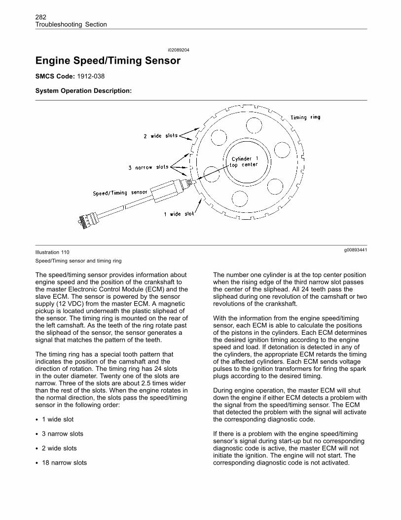
282Troubleshooting Section
i02089204
Engine Speed/Timing SensorSMCS Code: 1912-038
System Operation Description:
g00893441Illustration 110Speed/Timing sensor and timing ring
The speed/timing sensor provides information aboutengine speed and the position of the crankshaft tothe master Electronic Control Module (ECM) and theslave ECM. The sensor is powered by the sensorsupply (12 VDC) from the master ECM. A magneticpickup is located underneath the plastic sliphead ofthe sensor. The timing ring is mounted on the rear ofthe left camshaft. As the teeth of the ring rotate pastthe sliphead of the sensor, the sensor generates asignal that matches the pattern of the teeth.
The timing ring has a special tooth pattern thatindicates the position of the camshaft and thedirection of rotation. The timing ring has 24 slotsin the outer diameter. Twenty one of the slots arenarrow. Three of the slots are about 2.5 times widerthan the rest of the slots. When the engine rotates inthe normal direction, the slots pass the speed/timingsensor in the following order:
• 1 wide slot
• 3 narrow slots
• 2 wide slots
• 18 narrow slots
The number one cylinder is at the top center positionwhen the rising edge of the third narrow slot passesthe center of the sliphead. All 24 teeth pass thesliphead during one revolution of the camshaft or tworevolutions of the crankshaft.
With the information from the engine speed/timingsensor, each ECM is able to calculate the positionsof the pistons in the cylinders. Each ECM determinesthe desired ignition timing according to the enginespeed and load. If detonation is detected in any ofthe cylinders, the appropriate ECM retards the timingof the affected cylinders. Each ECM sends voltagepulses to the ignition transformers for firing the sparkplugs according to the desired timing.
During engine operation, the master ECM will shutdown the engine if either ECM detects a problem withthe signal from the speed/timing sensor. The ECMthat detected the problem with the signal will activatethe corresponding diagnostic code.
If there is a problem with the engine speed/timingsensor’s signal during start-up but no correspondingdiagnostic code is active, the master ECM will notinitiate the ignition. The engine will not start. Thecorresponding diagnostic code is not activated.
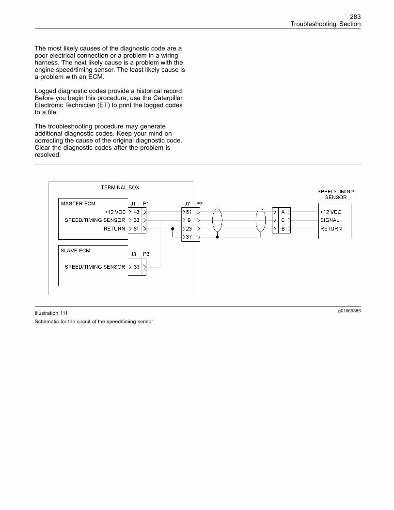
283Troubleshooting Section
The most likely causes of the diagnostic code are apoor electrical connection or a problem in a wiringharness. The next likely cause is a problem with theengine speed/timing sensor. The least likely cause isa problem with an ECM.
Logged diagnostic codes provide a historical record.Before you begin this procedure, use the CaterpillarElectronic Technician (ET) to print the logged codesto a file.
The troubleshooting procedure may generateadditional diagnostic codes. Keep your mind oncorrecting the cause of the original diagnostic code.Clear the diagnostic codes after the problem isresolved.
g01065386Illustration 111Schematic for the circuit of the speed/timing sensor
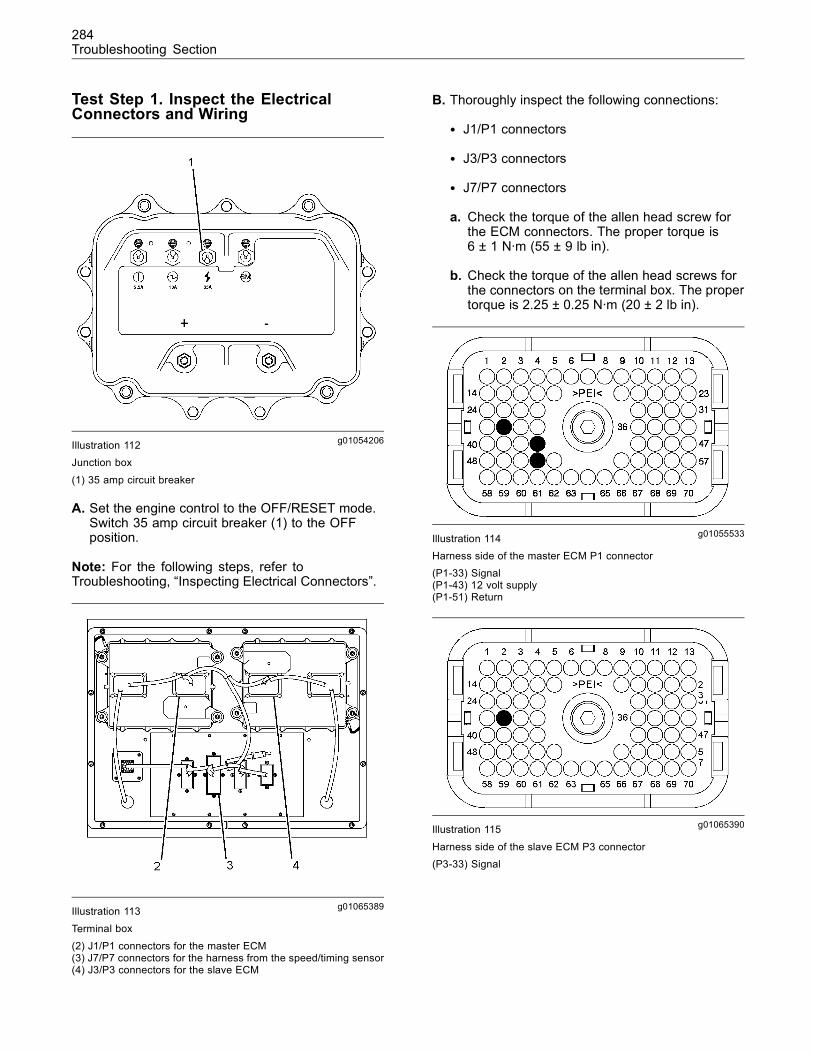
284Troubleshooting Section
Test Step 1. Inspect the ElectricalConnectors and Wiring
g01054206Illustration 112Junction box
(1) 35 amp circuit breaker
A. Set the engine control to the OFF/RESET mode.Switch 35 amp circuit breaker (1) to the OFFposition.
Note: For the following steps, refer toTroubleshooting, “Inspecting Electrical Connectors”.
g01065389Illustration 113
Terminal box
(2) J1/P1 connectors for the master ECM(3) J7/P7 connectors for the harness from the speed/timing sensor(4) J3/P3 connectors for the slave ECM
B. Thoroughly inspect the following connections:
• J1/P1 connectors
• J3/P3 connectors
• J7/P7 connectors
a. Check the torque of the allen head screw forthe ECM connectors. The proper torque is6 ± 1 N·m (55 ± 9 lb in).
b. Check the torque of the allen head screws forthe connectors on the terminal box. The propertorque is 2.25 ± 0.25 N·m (20 ± 2 lb in).
g01055533Illustration 114Harness side of the master ECM P1 connector(P1-33) Signal(P1-43) 12 volt supply(P1-51) Return
g01065390Illustration 115
Harness side of the slave ECM P3 connector(P3-33) Signal
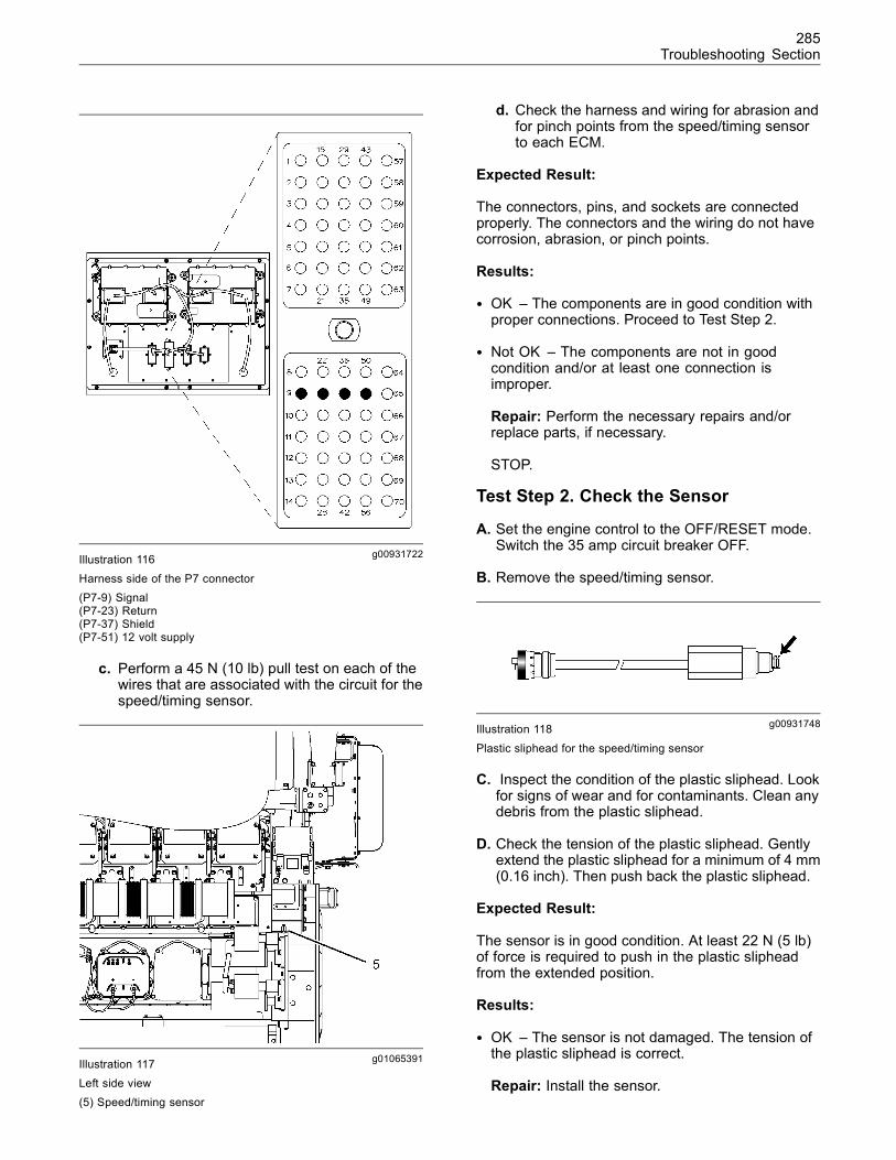
285Troubleshooting Section
g00931722Illustration 116
Harness side of the P7 connector(P7-9) Signal(P7-23) Return(P7-37) Shield(P7-51) 12 volt supply
c. Perform a 45 N (10 lb) pull test on each of thewires that are associated with the circuit for thespeed/timing sensor.
g01065391Illustration 117Left side view(5) Speed/timing sensor
d. Check the harness and wiring for abrasion andfor pinch points from the speed/timing sensorto each ECM.
Expected Result:
The connectors, pins, and sockets are connectedproperly. The connectors and the wiring do not havecorrosion, abrasion, or pinch points.
Results:
• OK – The components are in good condition withproper connections. Proceed to Test Step 2.
• Not OK – The components are not in goodcondition and/or at least one connection isimproper.
Repair: Perform the necessary repairs and/orreplace parts, if necessary.
STOP.
Test Step 2. Check the Sensor
A. Set the engine control to the OFF/RESET mode.Switch the 35 amp circuit breaker OFF.
B. Remove the speed/timing sensor.
g00931748Illustration 118
Plastic sliphead for the speed/timing sensor
C. Inspect the condition of the plastic sliphead. Lookfor signs of wear and for contaminants. Clean anydebris from the plastic sliphead.
D. Check the tension of the plastic sliphead. Gentlyextend the plastic sliphead for a minimum of 4 mm(0.16 inch). Then push back the plastic sliphead.
Expected Result:
The sensor is in good condition. At least 22 N (5 lb)of force is required to push in the plastic slipheadfrom the extended position.
Results:
• OK – The sensor is not damaged. The tension ofthe plastic sliphead is correct.
Repair: Install the sensor.
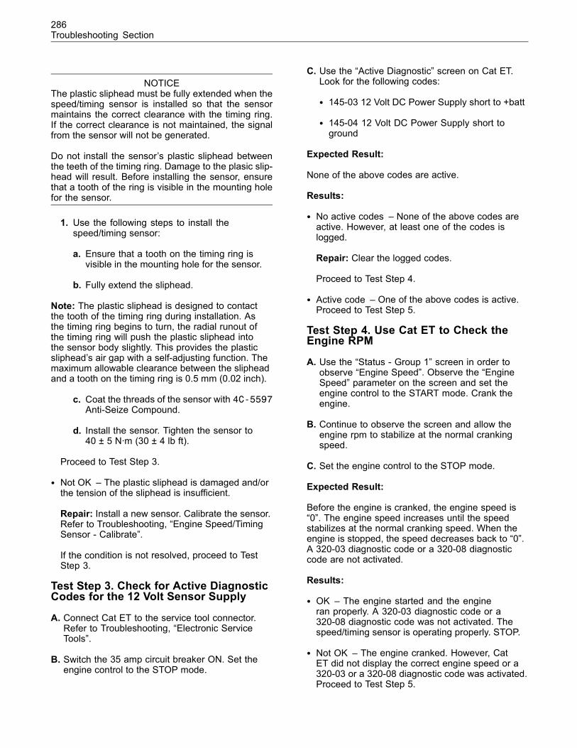
286Troubleshooting Section
NOTICEThe plastic sliphead must be fully extended when thespeed/timing sensor is installed so that the sensormaintains the correct clearance with the timing ring.If the correct clearance is not maintained, the signalfrom the sensor will not be generated.
Do not install the sensor’s plastic sliphead betweenthe teeth of the timing ring. Damage to the plasic slip-head will result. Before installing the sensor, ensurethat a tooth of the ring is visible in the mounting holefor the sensor.
1. Use the following steps to install thespeed/timing sensor:
a. Ensure that a tooth on the timing ring isvisible in the mounting hole for the sensor.
b. Fully extend the sliphead.
Note: The plastic sliphead is designed to contactthe tooth of the timing ring during installation. Asthe timing ring begins to turn, the radial runout ofthe timing ring will push the plastic sliphead intothe sensor body slightly. This provides the plasticsliphead’s air gap with a self-adjusting function. Themaximum allowable clearance between the slipheadand a tooth on the timing ring is 0.5 mm (0.02 inch).
c. Coat the threads of the sensor with 4C-5597Anti-Seize Compound.
d. Install the sensor. Tighten the sensor to40 ± 5 N·m (30 ± 4 lb ft).
Proceed to Test Step 3.
• Not OK – The plastic sliphead is damaged and/orthe tension of the sliphead is insufficient.
Repair: Install a new sensor. Calibrate the sensor.Refer to Troubleshooting, “Engine Speed/TimingSensor - Calibrate”.
If the condition is not resolved, proceed to TestStep 3.
Test Step 3. Check for Active DiagnosticCodes for the 12 Volt Sensor Supply
A. Connect Cat ET to the service tool connector.Refer to Troubleshooting, “Electronic ServiceTools”.
B. Switch the 35 amp circuit breaker ON. Set theengine control to the STOP mode.
C. Use the “Active Diagnostic” screen on Cat ET.Look for the following codes:
• 145-03 12 Volt DC Power Supply short to +batt
• 145-04 12 Volt DC Power Supply short toground
Expected Result:
None of the above codes are active.
Results:
• No active codes – None of the above codes areactive. However, at least one of the codes islogged.
Repair: Clear the logged codes.
Proceed to Test Step 4.
• Active code – One of the above codes is active.Proceed to Test Step 5.
Test Step 4. Use Cat ET to Check theEngine RPM
A. Use the “Status - Group 1” screen in order toobserve “Engine Speed”. Observe the “EngineSpeed” parameter on the screen and set theengine control to the START mode. Crank theengine.
B. Continue to observe the screen and allow theengine rpm to stabilize at the normal crankingspeed.
C. Set the engine control to the STOP mode.
Expected Result:
Before the engine is cranked, the engine speed is“0”. The engine speed increases until the speedstabilizes at the normal cranking speed. When theengine is stopped, the speed decreases back to “0”.A 320-03 diagnostic code or a 320-08 diagnosticcode are not activated.
Results:
• OK – The engine started and the engineran properly. A 320-03 diagnostic code or a320-08 diagnostic code was not activated. Thespeed/timing sensor is operating properly. STOP.
• Not OK – The engine cranked. However, CatET did not display the correct engine speed or a320-03 or a 320-08 diagnostic code was activated.Proceed to Test Step 5.
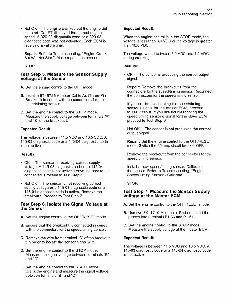
287Troubleshooting Section
• Not OK – The engine cranked but the engine didnot start. Cat ET displayed the correct enginespeed. A 320-03 diagnostic code or a 320-08diagnostic code was not activated. Each ECM isreceiving a valid signal.
Repair: Refer to Troubleshooting, “Engine CranksBut Will Not Start”. Make repairs, as needed.
STOP.
Test Step 5. Measure the Sensor SupplyVoltage at the Sensor
A. Set the engine control to the OFF mode.
B. Install a 8T-8726 Adapter Cable As (Three-PinBreakout) in series with the connectors for thespeed/timing sensor.
C. Set the engine control to the STOP mode.Measure the supply voltage between terminals “A”and “B” of the breakout t.
Expected Result:
The voltage is between 11.5 VDC and 13.5 VDC. A145-03 diagnostic code or a 145-04 diagnostic codeis not active.
Results:
• OK – The sensor is receiving correct supplyvoltage. A 145-03 diagnostic code or a 145-04diagnostic code is not active. Leave the breakout tconnected. Proceed to Test Step 6.
• Not OK – The sensor is not receiving correctsupply voltage or a 145-03 diagnostic code or a145-04 diagnostic code is active. Remove thebreakout t. Proceed to Test Step 7.
Test Step 6. Isolate the Signal Voltage atthe Sensor
A. Set the engine control to the OFF/RESET mode.
B. Ensure that the breakout t is connected in serieswith the connectors for the speed/timing sensor.
C. Remove the wire from terminal “C” of the breakoutt in order to isolate the sensor signal wire.
D. Set the engine control to the STOP mode.Measure the signal voltage between terminals “B”and “C”.
E. Set the engine control to the START mode.Crank the engine and measure the signal voltagebetween terminals “B” and “C”.
Expected Result:
When the engine control is in the STOP mode, thevoltage is less than 3.0 VDC or the voltage is greaterthan 10.0 VDC.
The voltage varied between 2.0 VDC and 4.0 VDCduring cranking.
Results:
• OK – The sensor is producing the correct outputsignal.
Repair: Remove the breakout t from theconnectors for the speed/timing sensor. Reconnectthe connectors for the speed/timing sensor.
If you are troubleshooting the speed/timingsensor’s signal for the master ECM, proceedto Test Step 8. If you are troubleshooting thespeed/timing sensor’s signal for the slave ECM,proceed to Test Step 9.
• Not OK – The sensor is not producing the correctoutput signal.
Repair: Set the engine control to the OFF/RESETmode. Switch the 35 amp circuit breaker OFF.
Remove the breakout t from the connectors for thespeed/timing sensor.
Install a new speed/timing sensor. Calibratethe sensor. Refer to Troubleshooting, “EngineSpeed/Timing Sensor - Calibrate”.
STOP.
Test Step 7. Measure the Sensor SupplyVoltage at the Master ECM
A. Set the engine control to the OFF/RESET mode.
B. Use two 7X-1710 Multimeter Probes. Insert theprobes into terminals P1-33 and P1-51.
C. Set the engine control to the STOP mode.Measure the supply voltage at the master ECM.
Expected Result:
The voltage is between 11.5 VDC and 13.5 VDC. A145-03 diagnostic code or a 145-04 diagnostic codeis not active.
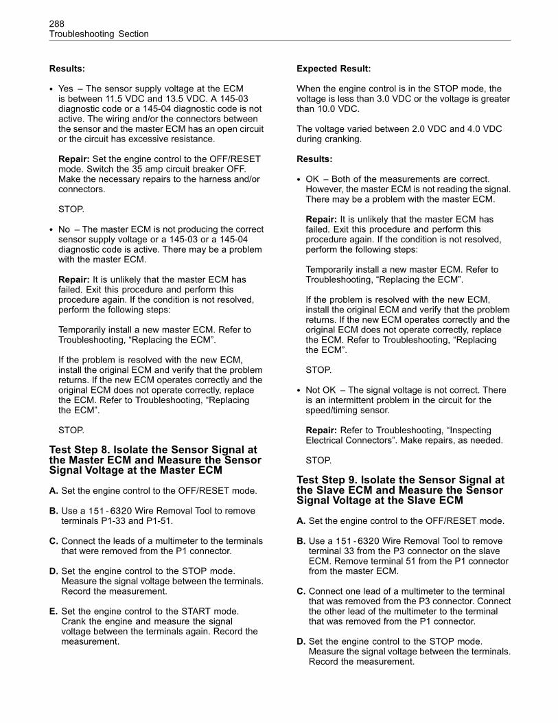
288Troubleshooting Section
Results:
• Yes – The sensor supply voltage at the ECMis between 11.5 VDC and 13.5 VDC. A 145-03diagnostic code or a 145-04 diagnostic code is notactive. The wiring and/or the connectors betweenthe sensor and the master ECM has an open circuitor the circuit has excessive resistance.
Repair: Set the engine control to the OFF/RESETmode. Switch the 35 amp circuit breaker OFF.Make the necessary repairs to the harness and/orconnectors.
STOP.
• No – The master ECM is not producing the correctsensor supply voltage or a 145-03 or a 145-04diagnostic code is active. There may be a problemwith the master ECM.
Repair: It is unlikely that the master ECM hasfailed. Exit this procedure and perform thisprocedure again. If the condition is not resolved,perform the following steps:
Temporarily install a new master ECM. Refer toTroubleshooting, “Replacing the ECM”.
If the problem is resolved with the new ECM,install the original ECM and verify that the problemreturns. If the new ECM operates correctly and theoriginal ECM does not operate correctly, replacethe ECM. Refer to Troubleshooting, “Replacingthe ECM”.
STOP.
Test Step 8. Isolate the Sensor Signal atthe Master ECM and Measure the SensorSignal Voltage at the Master ECM
A. Set the engine control to the OFF/RESET mode.
B. Use a 151-6320 Wire Removal Tool to removeterminals P1-33 and P1-51.
C. Connect the leads of a multimeter to the terminalsthat were removed from the P1 connector.
D. Set the engine control to the STOP mode.Measure the signal voltage between the terminals.Record the measurement.
E. Set the engine control to the START mode.Crank the engine and measure the signalvoltage between the terminals again. Record themeasurement.
Expected Result:
When the engine control is in the STOP mode, thevoltage is less than 3.0 VDC or the voltage is greaterthan 10.0 VDC.
The voltage varied between 2.0 VDC and 4.0 VDCduring cranking.
Results:
• OK – Both of the measurements are correct.However, the master ECM is not reading the signal.There may be a problem with the master ECM.
Repair: It is unlikely that the master ECM hasfailed. Exit this procedure and perform thisprocedure again. If the condition is not resolved,perform the following steps:
Temporarily install a new master ECM. Refer toTroubleshooting, “Replacing the ECM”.
If the problem is resolved with the new ECM,install the original ECM and verify that the problemreturns. If the new ECM operates correctly and theoriginal ECM does not operate correctly, replacethe ECM. Refer to Troubleshooting, “Replacingthe ECM”.
STOP.
• Not OK – The signal voltage is not correct. Thereis an intermittent problem in the circuit for thespeed/timing sensor.
Repair: Refer to Troubleshooting, “InspectingElectrical Connectors”. Make repairs, as needed.
STOP.
Test Step 9. Isolate the Sensor Signal atthe Slave ECM and Measure the SensorSignal Voltage at the Slave ECM
A. Set the engine control to the OFF/RESET mode.
B. Use a 151-6320 Wire Removal Tool to removeterminal 33 from the P3 connector on the slaveECM. Remove terminal 51 from the P1 connectorfrom the master ECM.
C. Connect one lead of a multimeter to the terminalthat was removed from the P3 connector. Connectthe other lead of the multimeter to the terminalthat was removed from the P1 connector.
D. Set the engine control to the STOP mode.Measure the signal voltage between the terminals.Record the measurement.
289Troubleshooting Section
E. Set the engine control to the START mode.Crank the engine and measure the signalvoltage between the terminals again. Record themeasurement.
Expected Result:
When the engine control is in the STOP mode, thevoltage is less than 3.0 VDC or the voltage is greaterthan 10.0 VDC.
The voltage varied between 2.0 VDC and 4.0 VDCduring cranking.
Results:
• OK – Both of the measurements are correct.However, the slave ECM is not reading the signal.There may be a problem with the slave ECM.
Repair: It is unlikely that the slave ECM has failed.Exit this procedure and perform this procedureagain. If the condition is not resolved, perform thefollowing steps:
Temporarily install a new slave ECM. Refer toTroubleshooting, “Replacing the ECM”.
If the problem is resolved with the new ECM,install the original ECM and verify that the problemreturns. If the new ECM operates correctly and theoriginal ECM does not operate correctly, replacethe ECM. Refer to Troubleshooting, “Replacingthe ECM”.
STOP.
• Not OK – The signal voltage is not correct. Thereis an intermittent problem in the circuit for thespeed/timing sensor.
Repair: Refer to Troubleshooting, “InspectingElectrical Connectors”. Make repairs, as needed.
STOP.
i02089347
Fuel Metering ValveSMCS Code: 1741-038
System Operation Description:
The fuel metering valve is an electronic gas valvethat controls the flow of fuel to the engine. The valveworks with the master Electronic Control Module(ECM) in order to ensure the correct flow of fuel in allconditions of engine operation.
The master ECM sends a command signal for the flowof fuel and information about the specific gravity ofthe gas to the fuel metering valve. The valve convertsthe command signal and the information into a valveposition that directly corresponds to the desired gasflow. The position of the valve is compensated bythese additional factors that are internal to the valve:absolute fuel pressure, differential pressure of thevalve, and fuel temperature.
The following procedure tests whether the commandsignal for the flow of fuel and the information aboutthe specific gravity of the gas is properly sentto the fuel metering valve by the master ECM.The command signal is a 180 hertz PWM signal.Information about the specific gravity of the gas issent to the fuel metering valve via the CAN Data Link.
The fuel metering valve sends information to themaster ECM via the CAN Data Link. This procedurealso tests whether the following information isproperly sent to the master ECM by the fuel meteringvalve: position of the fuel valve, absolute fuelpressure, differential pressure of the valve, and fueltemperature.
During normal operation, the valve receives twocommand signals from the ECM. One of the signalsis a digital signal that is received via the CAN datalink. The other signal is a pulse width modulatedsignal (PWM) that is received via a pair of wires. Thevalve will use the digital signal when both signals areavailable.
If the PWM signal is not available, the valvewill continue to use the digital signal. The ECMwill activate a 1446-05 diagnostic code. Engineperformance will be affected.
If the digital signal is not available, the valve will usethe PWM signal. The ECM will activate a 1446-09diagnostic code. Engine performance will be affected.
Status Indicator for the Fuel Metering Valve
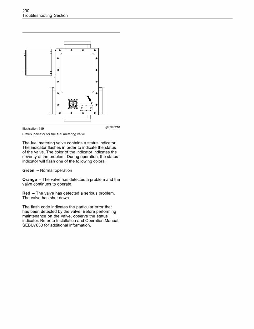
290Troubleshooting Section
g00996218Illustration 119
Status indicator for the fuel metering valve
The fuel metering valve contains a status indicator.The indicator flashes in order to indicate the statusof the valve. The color of the indicator indicates theseverity of the problem. During operation, the statusindicator will flash one of the following colors:
Green – Normal operation
Orange – The valve has detected a problem and thevalve continues to operate.
Red – The valve has detected a serious problem.The valve has shut down.
The flash code indicates the particular error thathas been detected by the valve. Before performingmaintenance on the valve, observe the statusindicator. Refer to Installation and Operation Manual,SEBU7630 for additional information.
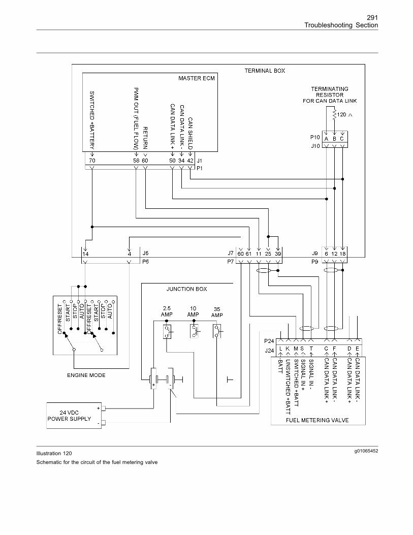
291Troubleshooting Section
g01065452Illustration 120
Schematic for the circuit of the fuel metering valve
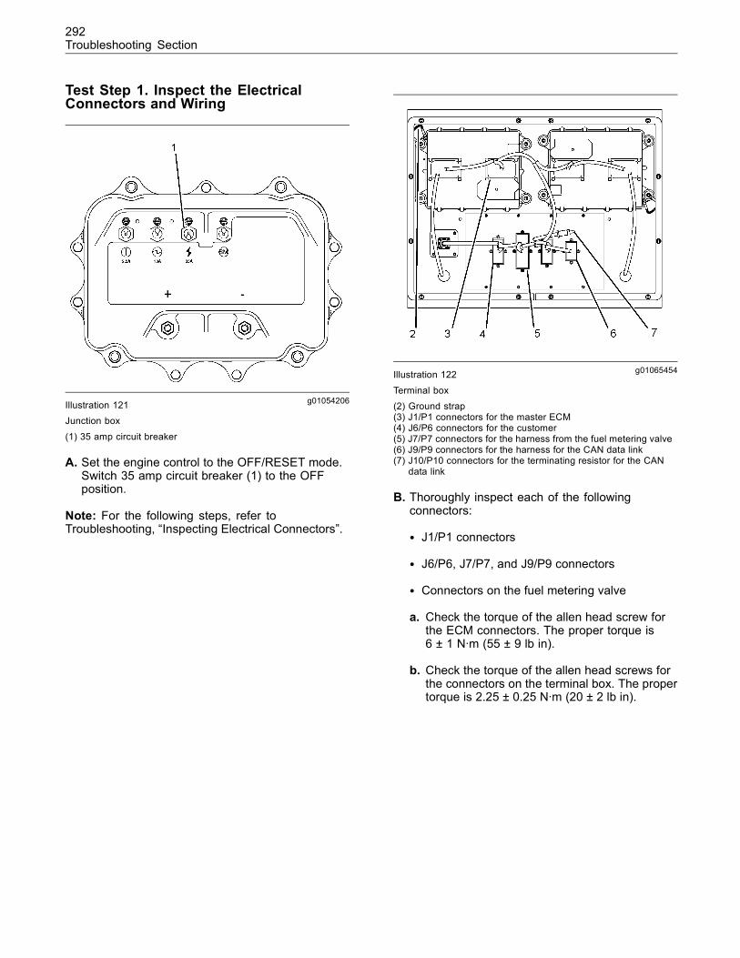
292Troubleshooting Section
Test Step 1. Inspect the ElectricalConnectors and Wiring
g01054206Illustration 121Junction box
(1) 35 amp circuit breaker
A. Set the engine control to the OFF/RESET mode.Switch 35 amp circuit breaker (1) to the OFFposition.
Note: For the following steps, refer toTroubleshooting, “Inspecting Electrical Connectors”.
g01065454Illustration 122
Terminal box(2) Ground strap(3) J1/P1 connectors for the master ECM(4) J6/P6 connectors for the customer(5) J7/P7 connectors for the harness from the fuel metering valve(6) J9/P9 connectors for the harness for the CAN data link(7) J10/P10 connectors for the terminating resistor for the CAN
data link
B. Thoroughly inspect each of the followingconnectors:
• J1/P1 connectors
• J6/P6, J7/P7, and J9/P9 connectors
• Connectors on the fuel metering valve
a. Check the torque of the allen head screw forthe ECM connectors. The proper torque is6 ± 1 N·m (55 ± 9 lb in).
b. Check the torque of the allen head screws forthe connectors on the terminal box. The propertorque is 2.25 ± 0.25 N·m (20 ± 2 lb in).
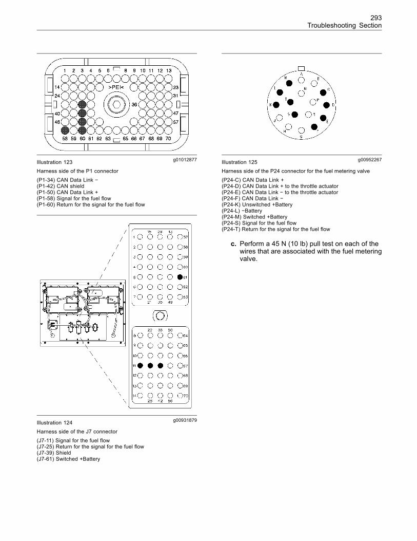
293Troubleshooting Section
g01012877Illustration 123Harness side of the P1 connector
(P1-34) CAN Data Link −(P1-42) CAN shield(P1-50) CAN Data Link +(P1-58) Signal for the fuel flow(P1-60) Return for the signal for the fuel flow
g00931879Illustration 124
Harness side of the J7 connector
(J7-11) Signal for the fuel flow(J7-25) Return for the signal for the fuel flow(J7-39) Shield(J7-61) Switched +Battery
g00952267Illustration 125Harness side of the P24 connector for the fuel metering valve
(P24-C) CAN Data Link +(P24-D) CAN Data Link + to the throttle actuator(P24-E) CAN Data Link − to the throttle actuator(P24-F) CAN Data Link −(P24-K) Unswitched +Battery(P24-L) −Battery(P24-M) Switched +Battery(P24-S) Signal for the fuel flow(P24-T) Return for the signal for the fuel flow
c. Perform a 45 N (10 lb) pull test on each of thewires that are associated with the fuel meteringvalve.
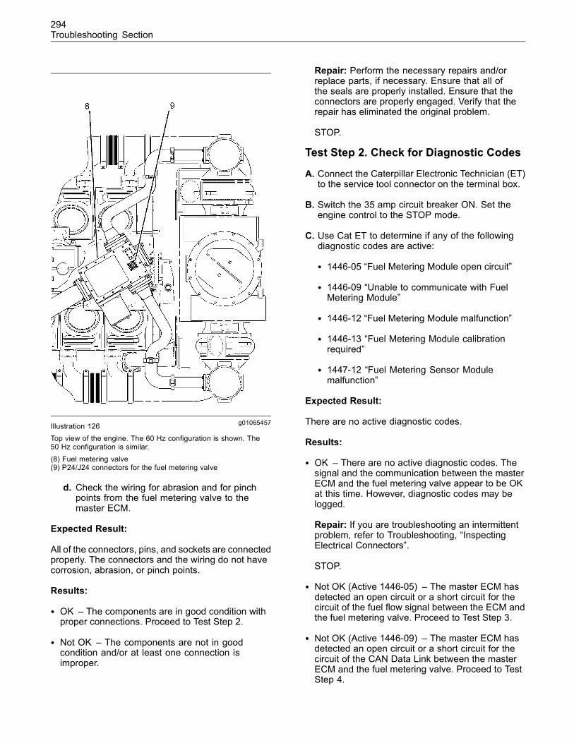
294Troubleshooting Section
g01065457Illustration 126Top view of the engine. The 60 Hz configuration is shown. The50 Hz configuration is similar.(8) Fuel metering valve(9) P24/J24 connectors for the fuel metering valve
d. Check the wiring for abrasion and for pinchpoints from the fuel metering valve to themaster ECM.
Expected Result:
All of the connectors, pins, and sockets are connectedproperly. The connectors and the wiring do not havecorrosion, abrasion, or pinch points.
Results:
• OK – The components are in good condition withproper connections. Proceed to Test Step 2.
• Not OK – The components are not in goodcondition and/or at least one connection isimproper.
Repair: Perform the necessary repairs and/orreplace parts, if necessary. Ensure that all ofthe seals are properly installed. Ensure that theconnectors are properly engaged. Verify that therepair has eliminated the original problem.
STOP.
Test Step 2. Check for Diagnostic Codes
A. Connect the Caterpillar Electronic Technician (ET)to the service tool connector on the terminal box.
B. Switch the 35 amp circuit breaker ON. Set theengine control to the STOP mode.
C. Use Cat ET to determine if any of the followingdiagnostic codes are active:
• 1446-05 “Fuel Metering Module open circuit”
• 1446-09 “Unable to communicate with FuelMetering Module”
• 1446-12 “Fuel Metering Module malfunction”
• 1446-13 “Fuel Metering Module calibrationrequired”
• 1447-12 “Fuel Metering Sensor Modulemalfunction”
Expected Result:
There are no active diagnostic codes.
Results:
• OK – There are no active diagnostic codes. Thesignal and the communication between the masterECM and the fuel metering valve appear to be OKat this time. However, diagnostic codes may belogged.
Repair: If you are troubleshooting an intermittentproblem, refer to Troubleshooting, “InspectingElectrical Connectors”.
STOP.
• Not OK (Active 1446-05) – The master ECM hasdetected an open circuit or a short circuit for thecircuit of the fuel flow signal between the ECM andthe fuel metering valve. Proceed to Test Step 3.
• Not OK (Active 1446-09) – The master ECM hasdetected an open circuit or a short circuit for thecircuit of the CAN Data Link between the masterECM and the fuel metering valve. Proceed to TestStep 4.
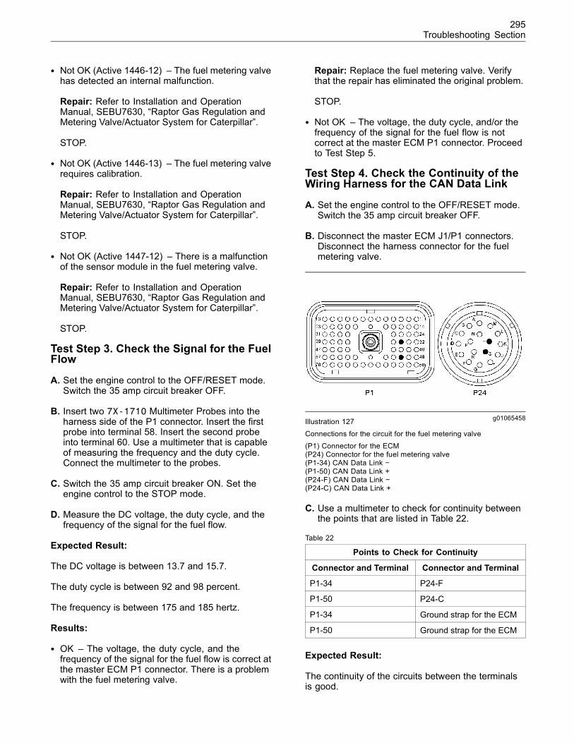
295Troubleshooting Section
• Not OK (Active 1446-12) – The fuel metering valvehas detected an internal malfunction.
Repair: Refer to Installation and OperationManual, SEBU7630, “Raptor Gas Regulation andMetering Valve/Actuator System for Caterpillar”.
STOP.
• Not OK (Active 1446-13) – The fuel metering valverequires calibration.
Repair: Refer to Installation and OperationManual, SEBU7630, “Raptor Gas Regulation andMetering Valve/Actuator System for Caterpillar”.
STOP.
• Not OK (Active 1447-12) – There is a malfunctionof the sensor module in the fuel metering valve.
Repair: Refer to Installation and OperationManual, SEBU7630, “Raptor Gas Regulation andMetering Valve/Actuator System for Caterpillar”.
STOP.
Test Step 3. Check the Signal for the FuelFlow
A. Set the engine control to the OFF/RESET mode.Switch the 35 amp circuit breaker OFF.
B. Insert two 7X-1710 Multimeter Probes into theharness side of the P1 connector. Insert the firstprobe into terminal 58. Insert the second probeinto terminal 60. Use a multimeter that is capableof measuring the frequency and the duty cycle.Connect the multimeter to the probes.
C. Switch the 35 amp circuit breaker ON. Set theengine control to the STOP mode.
D. Measure the DC voltage, the duty cycle, and thefrequency of the signal for the fuel flow.
Expected Result:
The DC voltage is between 13.7 and 15.7.
The duty cycle is between 92 and 98 percent.
The frequency is between 175 and 185 hertz.
Results:
• OK – The voltage, the duty cycle, and thefrequency of the signal for the fuel flow is correct atthe master ECM P1 connector. There is a problemwith the fuel metering valve.
Repair: Replace the fuel metering valve. Verifythat the repair has eliminated the original problem.
STOP.
• Not OK – The voltage, the duty cycle, and/or thefrequency of the signal for the fuel flow is notcorrect at the master ECM P1 connector. Proceedto Test Step 5.
Test Step 4. Check the Continuity of theWiring Harness for the CAN Data Link
A. Set the engine control to the OFF/RESET mode.Switch the 35 amp circuit breaker OFF.
B. Disconnect the master ECM J1/P1 connectors.Disconnect the harness connector for the fuelmetering valve.
g01065458Illustration 127Connections for the circuit for the fuel metering valve(P1) Connector for the ECM(P24) Connector for the fuel metering valve(P1-34) CAN Data Link −(P1-50) CAN Data Link +(P24-F) CAN Data Link −(P24-C) CAN Data Link +
C. Use a multimeter to check for continuity betweenthe points that are listed in Table 22.
Table 22
Points to Check for Continuity
Connector and Terminal Connector and Terminal
P1-34 P24-F
P1-50 P24-C
P1-34 Ground strap for the ECM
P1-50 Ground strap for the ECM
Expected Result:
The continuity of the circuits between the terminalsis good.
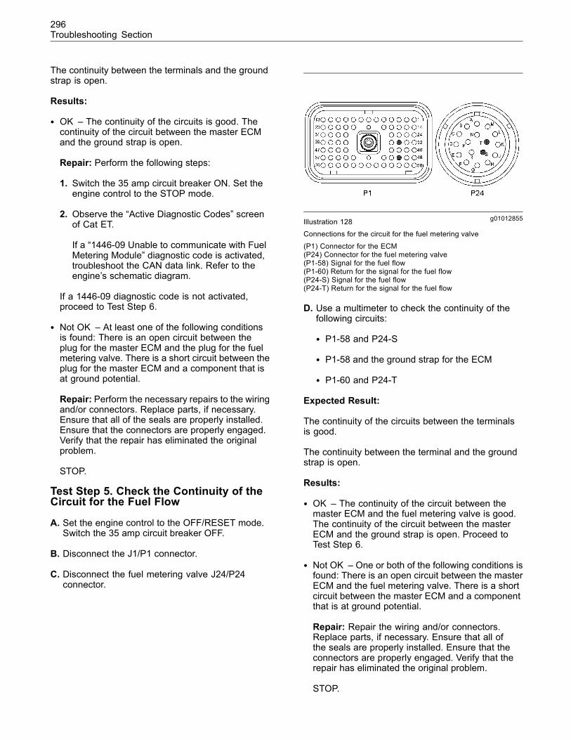
296Troubleshooting Section
The continuity between the terminals and the groundstrap is open.
Results:
• OK – The continuity of the circuits is good. Thecontinuity of the circuit between the master ECMand the ground strap is open.
Repair: Perform the following steps:
1. Switch the 35 amp circuit breaker ON. Set theengine control to the STOP mode.
2. Observe the “Active Diagnostic Codes” screenof Cat ET.
If a “1446-09 Unable to communicate with FuelMetering Module” diagnostic code is activated,troubleshoot the CAN data link. Refer to theengine’s schematic diagram.
If a 1446-09 diagnostic code is not activated,proceed to Test Step 6.
• Not OK – At least one of the following conditionsis found: There is an open circuit between theplug for the master ECM and the plug for the fuelmetering valve. There is a short circuit between theplug for the master ECM and a component that isat ground potential.
Repair: Perform the necessary repairs to the wiringand/or connectors. Replace parts, if necessary.Ensure that all of the seals are properly installed.Ensure that the connectors are properly engaged.Verify that the repair has eliminated the originalproblem.
STOP.
Test Step 5. Check the Continuity of theCircuit for the Fuel Flow
A. Set the engine control to the OFF/RESET mode.Switch the 35 amp circuit breaker OFF.
B. Disconnect the J1/P1 connector.
C. Disconnect the fuel metering valve J24/P24connector.
g01012855Illustration 128Connections for the circuit for the fuel metering valve
(P1) Connector for the ECM(P24) Connector for the fuel metering valve(P1-58) Signal for the fuel flow(P1-60) Return for the signal for the fuel flow(P24-S) Signal for the fuel flow(P24-T) Return for the signal for the fuel flow
D. Use a multimeter to check the continuity of thefollowing circuits:
• P1-58 and P24-S
• P1-58 and the ground strap for the ECM
• P1-60 and P24-T
Expected Result:
The continuity of the circuits between the terminalsis good.
The continuity between the terminal and the groundstrap is open.
Results:
• OK – The continuity of the circuit between themaster ECM and the fuel metering valve is good.The continuity of the circuit between the masterECM and the ground strap is open. Proceed toTest Step 6.
• Not OK – One or both of the following conditions isfound: There is an open circuit between the masterECM and the fuel metering valve. There is a shortcircuit between the master ECM and a componentthat is at ground potential.
Repair: Repair the wiring and/or connectors.Replace parts, if necessary. Ensure that all ofthe seals are properly installed. Ensure that theconnectors are properly engaged. Verify that therepair has eliminated the original problem.
STOP.
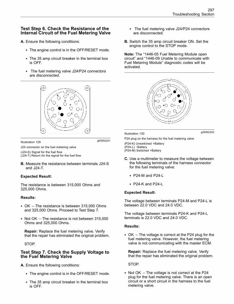
297Troubleshooting Section
Test Step 6. Check the Resistance of theInternal Circuit of the Fuel Metering Valve
A. Ensure the following conditions:
• The engine control is in the OFF/RESET mode.
• The 35 amp circuit breaker in the terminal boxis OFF.
• The fuel metering valve J24/P24 connectorsare disconnected.
g00952241Illustration 129
J24 connector on the fuel metering valve(J24-S) Signal for the fuel flow(J24-T) Return for the signal for the fuel flow
B. Measure the resistance between terminals J24-Sand J24-T.
Expected Result:
The resistance is between 315,000 Ohms and325,000 Ohms.
Results:
• OK – The resistance is between 315,000 Ohmsand 325,000 Ohms. Proceed to Test Step 7.
• Not OK – The resistance is not between 315,000Ohms and 325,000 Ohms.
Repair: Replace the fuel metering valve. Verifythat the repair has eliminated the original problem.
STOP.
Test Step 7. Check the Supply Voltage tothe Fuel Metering Valve
A. Ensure the following conditions:
• The engine control is in the OFF/RESET mode.
• The 35 amp circuit breaker in the terminal boxis OFF.
• The fuel metering valve J24/P24 connectorsare disconnected.
B. Switch the 35 amp circuit breaker ON. Set theengine control to the STOP mode.
Note: The “1446-05 Fuel Metering Module opencircuit” and “1446-09 Unable to communicate withFuel Metering Module” diagnostic codes will beactivated.
g00952242Illustration 130P24 plug on the harness for the fuel metering valve(P24-K) Unswitched +Battery(P24-L) −Battery(P24-M) Switched +Battery
C. Use a multimeter to measure the voltage betweenthe following terminals of the harness connectorfor the fuel metering valve:
• P24-M and P24-L
• P24-K and P24-L
Expected Result:
The voltage between terminals P24-M and P24-L isbetween 22.0 VDC and 24.0 VDC.
The voltage between terminals P24-K and P24-Lterminals is 22.0 VDC and 24.0 VDC.
Results:
• OK – The voltage is correct at the P24 plug for thefuel metering valve. However, the fuel meteringvalve is not communicating with the master ECM.
Repair: Replace the fuel metering valve. Verifythat the repair has eliminated the original problem.
STOP.
• Not OK – The voltage is not correct at the P24plug for the fuel metering valve. There is an opencircuit or a short circuit in the harness to the fuelmetering valve.
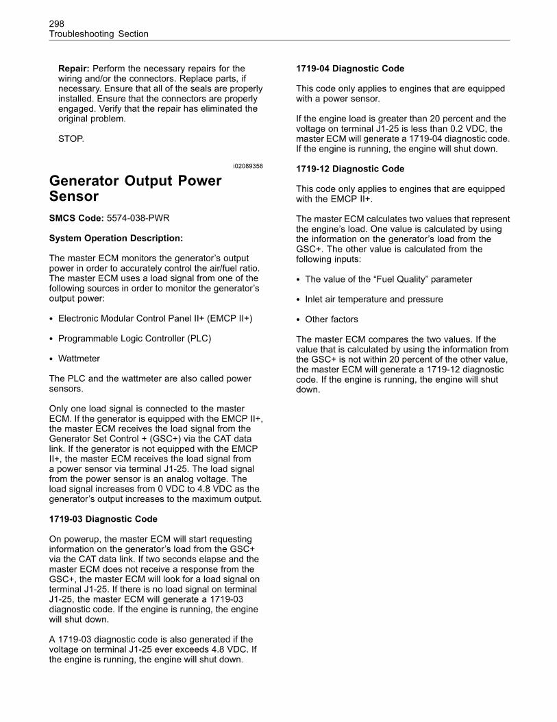
298Troubleshooting Section
Repair: Perform the necessary repairs for thewiring and/or the connectors. Replace parts, ifnecessary. Ensure that all of the seals are properlyinstalled. Ensure that the connectors are properlyengaged. Verify that the repair has eliminated theoriginal problem.
STOP.
i02089358
Generator Output PowerSensorSMCS Code: 5574-038-PWR
System Operation Description:
The master ECM monitors the generator’s outputpower in order to accurately control the air/fuel ratio.The master ECM uses a load signal from one of thefollowing sources in order to monitor the generator’soutput power:
• Electronic Modular Control Panel II+ (EMCP II+)
• Programmable Logic Controller (PLC)
• Wattmeter
The PLC and the wattmeter are also called powersensors.
Only one load signal is connected to the masterECM. If the generator is equipped with the EMCP II+,the master ECM receives the load signal from theGenerator Set Control + (GSC+) via the CAT datalink. If the generator is not equipped with the EMCPII+, the master ECM receives the load signal froma power sensor via terminal J1-25. The load signalfrom the power sensor is an analog voltage. Theload signal increases from 0 VDC to 4.8 VDC as thegenerator’s output increases to the maximum output.
1719-03 Diagnostic Code
On powerup, the master ECM will start requestinginformation on the generator’s load from the GSC+via the CAT data link. If two seconds elapse and themaster ECM does not receive a response from theGSC+, the master ECM will look for a load signal onterminal J1-25. If there is no load signal on terminalJ1-25, the master ECM will generate a 1719-03diagnostic code. If the engine is running, the enginewill shut down.
A 1719-03 diagnostic code is also generated if thevoltage on terminal J1-25 ever exceeds 4.8 VDC. Ifthe engine is running, the engine will shut down.
1719-04 Diagnostic Code
This code only applies to engines that are equippedwith a power sensor.
If the engine load is greater than 20 percent and thevoltage on terminal J1-25 is less than 0.2 VDC, themaster ECM will generate a 1719-04 diagnostic code.If the engine is running, the engine will shut down.
1719-12 Diagnostic Code
This code only applies to engines that are equippedwith the EMCP II+.
The master ECM calculates two values that representthe engine’s load. One value is calculated by usingthe information on the generator’s load from theGSC+. The other value is calculated from thefollowing inputs:
• The value of the “Fuel Quality” parameter
• Inlet air temperature and pressure
• Other factors
The master ECM compares the two values. If thevalue that is calculated by using the information fromthe GSC+ is not within 20 percent of the other value,the master ECM will generate a 1719-12 diagnosticcode. If the engine is running, the engine will shutdown.
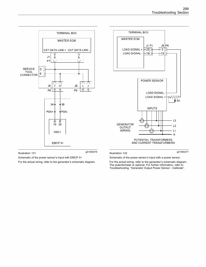
299Troubleshooting Section
g01065476Illustration 131Schematic of the power sensor’s input with EMCP II+For the actual wiring, refer to the generator’s schematic diagram.
g01065477Illustration 132Schematic of the power sensor’s input with a power sensorFor the actual wiring, refer to the generator’s schematic diagram.The potentiometer is optional. For further information, refer toTroubleshooting, “Generator Output Power Sensor - Calibrate”.
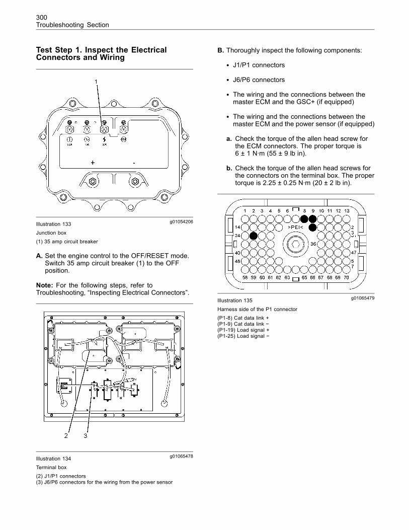
300Troubleshooting Section
Test Step 1. Inspect the ElectricalConnectors and Wiring
g01054206Illustration 133Junction box
(1) 35 amp circuit breaker
A. Set the engine control to the OFF/RESET mode.Switch 35 amp circuit breaker (1) to the OFFposition.
Note: For the following steps, refer toTroubleshooting, “Inspecting Electrical Connectors”.
g01065478Illustration 134
Terminal box
(2) J1/P1 connectors(3) J6/P6 connectors for the wiring from the power sensor
B. Thoroughly inspect the following components:
• J1/P1 connectors
• J6/P6 connectors
• The wiring and the connections between themaster ECM and the GSC+ (if equipped)
• The wiring and the connections between themaster ECM and the power sensor (if equipped)
a. Check the torque of the allen head screw forthe ECM connectors. The proper torque is6 ± 1 N·m (55 ± 9 lb in).
b. Check the torque of the allen head screws forthe connectors on the terminal box. The propertorque is 2.25 ± 0.25 N·m (20 ± 2 lb in).
g01065479Illustration 135
Harness side of the P1 connector(P1-8) Cat data link +(P1-9) Cat data link −(P1-19) Load signal +(P1-25) Load signal −
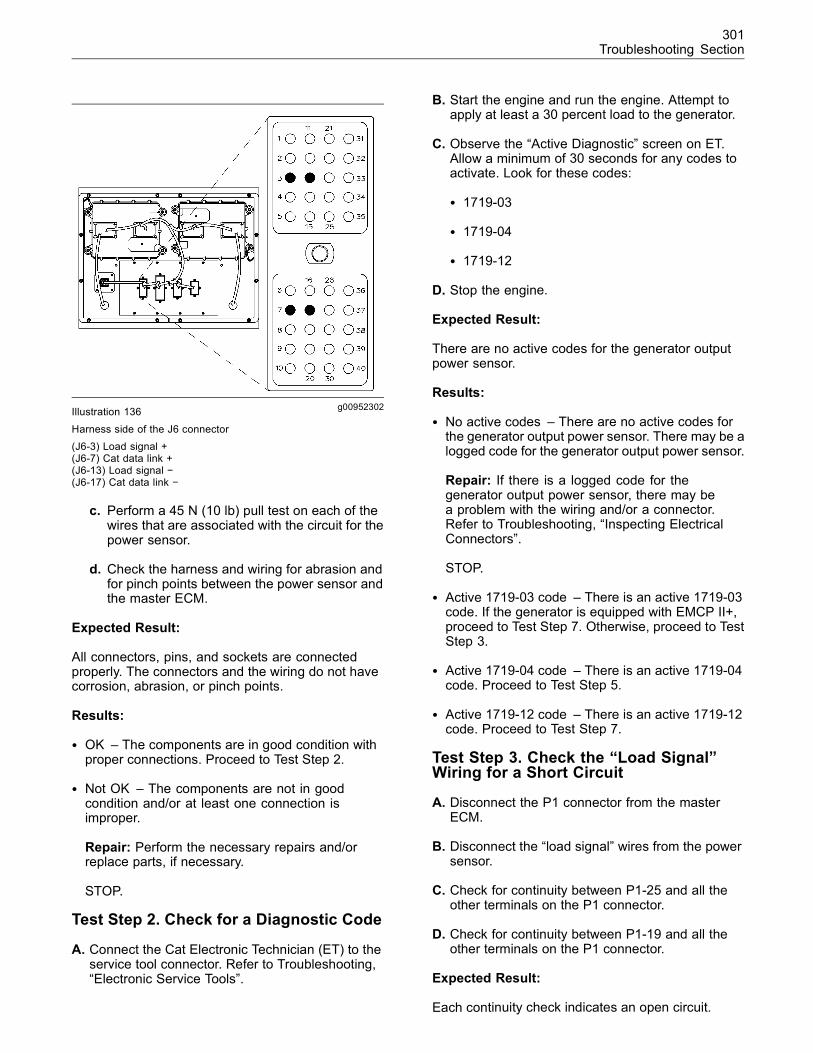
301Troubleshooting Section
g00952302Illustration 136
Harness side of the J6 connector(J6-3) Load signal +(J6-7) Cat data link +(J6-13) Load signal −(J6-17) Cat data link −
c. Perform a 45 N (10 lb) pull test on each of thewires that are associated with the circuit for thepower sensor.
d. Check the harness and wiring for abrasion andfor pinch points between the power sensor andthe master ECM.
Expected Result:
All connectors, pins, and sockets are connectedproperly. The connectors and the wiring do not havecorrosion, abrasion, or pinch points.
Results:
• OK – The components are in good condition withproper connections. Proceed to Test Step 2.
• Not OK – The components are not in goodcondition and/or at least one connection isimproper.
Repair: Perform the necessary repairs and/orreplace parts, if necessary.
STOP.
Test Step 2. Check for a Diagnostic Code
A. Connect the Cat Electronic Technician (ET) to theservice tool connector. Refer to Troubleshooting,“Electronic Service Tools”.
B. Start the engine and run the engine. Attempt toapply at least a 30 percent load to the generator.
C. Observe the “Active Diagnostic” screen on ET.Allow a minimum of 30 seconds for any codes toactivate. Look for these codes:
• 1719-03
• 1719-04
• 1719-12
D. Stop the engine.
Expected Result:
There are no active codes for the generator outputpower sensor.
Results:
• No active codes – There are no active codes forthe generator output power sensor. There may be alogged code for the generator output power sensor.
Repair: If there is a logged code for thegenerator output power sensor, there may bea problem with the wiring and/or a connector.Refer to Troubleshooting, “Inspecting ElectricalConnectors”.
STOP.
• Active 1719-03 code – There is an active 1719-03code. If the generator is equipped with EMCP II+,proceed to Test Step 7. Otherwise, proceed to TestStep 3.
• Active 1719-04 code – There is an active 1719-04code. Proceed to Test Step 5.
• Active 1719-12 code – There is an active 1719-12code. Proceed to Test Step 7.
Test Step 3. Check the “Load Signal”Wiring for a Short Circuit
A. Disconnect the P1 connector from the masterECM.
B. Disconnect the “load signal” wires from the powersensor.
C. Check for continuity between P1-25 and all theother terminals on the P1 connector.
D. Check for continuity between P1-19 and all theother terminals on the P1 connector.
Expected Result:
Each continuity check indicates an open circuit.
302Troubleshooting Section
Results:
• OK – Each continuity check indicates an opencircuit. The “load signal” wiring does not have ashort circuit.
Repair: Reconnect the P1 connector. Reconnectthe “load signal” wires to the power sensor. Besure to observe the correct polarity.
Proceed to Test Step 4.
• Not OK – At least one continuity check indicatesa short circuit.
Repair: The problem may be between the P1connector and the J6 connector. Alternatively, theproblem may be between the J6 connector andthe power sensor.
Repair the harness or the connection, whenpossible. Replace parts, if necessary. Verify thatthe problem is resolved.
STOP.
Test Step 4. Check the “Load Signal”Wiring for Continuity
Note: A potentiometer may be installed in the “loadsignal” wiring. A high resistance reading may becaused by the potentiometer.
A. Check the continuity of the wiring between P1-25and the power sensor.
B. Check the continuity of the wiring between P1-19and the power sensor.
Expected Result:
The “load signal” wiring has continuity.
Results:
• OK – The “load signal” wiring has continuity.Proceed to Test Step 6.
• Not OK – The “load signal” wiring has an opencircuit. The open circuit may be in a wire, in aconnector, or in the potentiometer.
Repair: Repair the component, when possible.Replace parts, if necessary. Verify that the originalproblem is resolved.
STOP.
Test Step 5. Check the “Load Signal +”Wire for a Short Circuit
A. Verify that the engine control is in the OFF/RESETmode and that the 35 amp circuit breaker is OFF.
B. Disconnect the P1 connector from the masterECM.
C. Disconnect the “load signal +” wire from the powersensor.
D. Check for continuity between P1-25 and all theother terminals on the P1 connector.
Expected Result:
Each continuity check indicates an open circuit.
Results:
• OK – Each continuity check indicates an opencircuit. The “load signal +” wire does not have ashort circuit.
Repair: Reconnect the P1 connector. Reconnectthe “load signal +” wire to the power sensor.
Proceed to Test Step 6.
• Not OK – At least one continuity check indicatesa short circuit. There is a short circuit in a harnessor in a connector.
Repair: The problem may be between the P1connector and the J6 connector. Alternatively, theproblem may be between the J6 connector and thegenerator output power sensor.
Repair the harness or the connection, whenpossible. Replace parts, if necessary. Verify thatthe problem is resolved.
STOP.
Test Step 6. Check the Power Sensor, thePotential Transformers, and the CurrentTransformers
Verify that the power sensor, the potentialtransformers, and the current transformers areoperating correctly. Refer to the appropriate serviceliterature for the components.
Expected Result:
The components are operating correctly.
303Troubleshooting Section
Results:
• OK – The components are operating correctly.Proceed to Test Step 13.
• Not OK – At least one of the components is notoperating correctly.
Repair: Repair the component, when possible.Replace the component, if necessary. Verify thatthe original problem is resolved.
STOP.
Test Step 7. Check the Continuity of theCat Data Link
A. Set the engine control to the OFF/RESET mode.Switch the 35 amp circuit breaker OFF.
B. Disconnect Cat ET from the service tool connector.
C. Disconnect the wiring for the Cat data link fromthe GSC+.
D. Disconnect the P1 connector from the masterECM.
E. Measure the resistance between the points thatare listed in Table 23. During each measurement,wiggle the wires in the harness in order to checkfor an intermittent problem. Be sure to wiggle thewires near each of the connectors.
Table 23
Resistance Measurements for the Cat Data Link
Connector and Terminal Connector and Terminal
P1-8 Terminal 19 on the GSC+
P1-9 Terminal 20 on the GSC+
P1-8 Ground strap for the ECM
P1-9 Ground strap for the ECM
Expected Result:
Each check of the resistance between the terminalsis less than 5 Ohms.
Each check of the resistance between the terminalsand the ground strap is greater than 20,000 Ohms.
Results:
• OK – Each check of the resistance for the Catdata link is within the specification. The wiring forthe Cat data link appears to be OK.
Repair: Perform the following procedure:
1. Reconnect the wiring to the GSC+. Be sure toconnect each wire to the appropriate terminal.
2. Reconnect the P1 connector.
Proceed to Test Step 8.
• Not OK – At least one check of the resistance forthe Cat data link is incorrect. There is a problemwith the wiring for the Cat data link.
Repair: Repair the connection and/or the wire,when possible. Replace parts, if necessary. Verifythat the original problem is resolved.
STOP.
Test Step 8. Check the GSC+
Verify that the GSC+ is operating correctly. Refer tothe appropriate service literature for the EMCP II+.
Expected Result:
The GSC+ is operating correctly.
Results:
• OK – The GSC+ is operating correctly. Proceed toTest Step 13.
• Not OK – The GSC+ is not operating correctly.
Repair: Repair the GSC+. Refer to the appropriateservice literature for the EMCP II+. Verify that theoriginal problem is resolved.
STOP.
Test Step 9. Check the “Fuel Quality”parameter
Verify that the value of the “Fuel Quality” parameteris correct. Use the value that is obtained from theCaterpillar Software, LEKQ6378, “Methane NumberProgram”.
Expected Result:
The value of the “Fuel Quality” parameter is correct.
Results:
• OK – The value of the “Fuel Quality” parameter iscorrect. Proceed to Test Step 10.
• Not OK – The value of the “Fuel Quality” parameteris not correct.
Repair: Enter the correct value for the parameter.Verify that the original problem is resolved.
STOP.
304Troubleshooting Section
Test Step 10. Check the Sensors for theAir Inlet Manifold
A. If the engine is running, stop the engine.
B. Connect a pressure gauge and a temperaturesensor to the air inlet manifold.
C. View the Status Group 1 on Cat ET. Comparethe values on the instruments with the followingparameters:
• “Inlet manifold air pressure (abs)”
• “Inlet air temperature”
Expected Result:
The values of the parameters are correct.
Results:
• OK – The values of the parameters are correct.Proceed to Test Step 8.
• Not OK – One or both of the values of theparameters are incorrect.
Repair: Replace the appropriate sensor. Verify thatthe original problem is resolved.
STOP.
Test Step 11. Check the GSC+
Verify that the GSC+ is operating correctly. Refer tothe appropriate service literature for the EMCP II+.
Expected Result:
The GSC+ is operating correctly.
Results:
• OK – The GSC+ is operating correctly. Proceed toTest Step 12.
• Not OK – The GSC+ is not operating correctly.
Repair: Repair the GSC+. Refer to the appropriateservice literature for the EMCP II+. Verify that theoriginal problem is resolved.
STOP.
Test Step 12. Verify that the Output PowerReading is Correct
Operate the generator at various loads. Verify thatthe value of the “Generator Real kW” parameter inStatus Group 1 is within 1 percent of the generator’soutput power.
Expected Result:
The value of the “Generator Real kW” parameter iscorrect.
Results:
• OK – The value of the “Generator Real kW”parameter is correct. Proceed to Test Step 13.
• Not OK – The value of the “Generator Real kW”parameter is incorrect.
Repair: Refer to Troubleshooting, “GeneratorOutput Power Readings Do Not Match”.
STOP.
Test Step 13. Check the Master ECM
It is unlikely that the master ECM has failed. Exit thisprocedure and perform this procedure again. If theproblem is not resolved, temporarily install a newmaster ECM. Refer to Troubleshooting, “Replacingthe ECM”.
Expected Result:
The problem is resolved when a new master ECMis installed.
Results:
• OK – The problem is resolved when a new masterECM is installed.
Repair: Install the original ECM and verify that theproblem returns. If the new ECM operates correctlyand the original ECM does not operate correctly,replace the ECM.
STOP.
• Not OK – The problem is not resolved when a newECM is installed.
Repair: Reinstall the original ECM. Consult withCaterpillar customer service for large gas engines.
STOP.
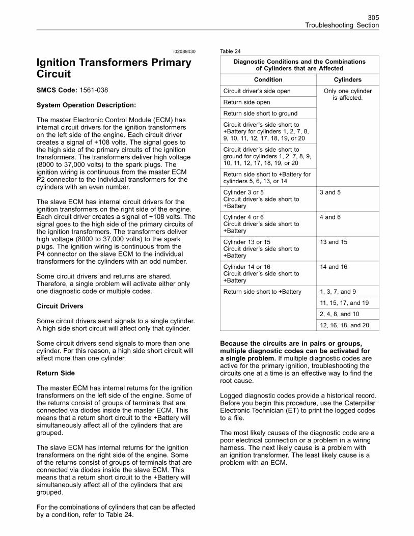
305Troubleshooting Section
i02089430
Ignition Transformers PrimaryCircuitSMCS Code: 1561-038
System Operation Description:
The master Electronic Control Module (ECM) hasinternal circuit drivers for the ignition transformerson the left side of the engine. Each circuit drivercreates a signal of +108 volts. The signal goes tothe high side of the primary circuits of the ignitiontransformers. The transformers deliver high voltage(8000 to 37,000 volts) to the spark plugs. Theignition wiring is continuous from the master ECMP2 connector to the individual transformers for thecylinders with an even number.
The slave ECM has internal circuit drivers for theignition transformers on the right side of the engine.Each circuit driver creates a signal of +108 volts. Thesignal goes to the high side of the primary circuits ofthe ignition transformers. The transformers deliverhigh voltage (8000 to 37,000 volts) to the sparkplugs. The ignition wiring is continuous from theP4 connector on the slave ECM to the individualtransformers for the cylinders with an odd number.
Some circuit drivers and returns are shared.Therefore, a single problem will activate either onlyone diagnostic code or multiple codes.
Circuit Drivers
Some circuit drivers send signals to a single cylinder.A high side short circuit will affect only that cylinder.
Some circuit drivers send signals to more than onecylinder. For this reason, a high side short circuit willaffect more than one cylinder.
Return Side
The master ECM has internal returns for the ignitiontransformers on the left side of the engine. Some ofthe returns consist of groups of terminals that areconnected via diodes inside the master ECM. Thismeans that a return short circuit to the +Battery willsimultaneously affect all of the cylinders that aregrouped.
The slave ECM has internal returns for the ignitiontransformers on the right side of the engine. Someof the returns consist of groups of terminals that areconnected via diodes inside the slave ECM. Thismeans that a return short circuit to the +Battery willsimultaneously affect all of the cylinders that aregrouped.
For the combinations of cylinders that can be affectedby a condition, refer to Table 24.
Table 24
Diagnostic Conditions and the Combinationsof Cylinders that are Affected
Condition Cylinders
Circuit driver’s side open
Return side open
Return side short to ground
Circuit driver’s side short to+Battery for cylinders 1, 2, 7, 8,9, 10, 11, 12, 17, 18, 19, or 20
Circuit driver’s side short toground for cylinders 1, 2, 7, 8, 9,10, 11, 12, 17, 18, 19, or 20
Return side short to +Battery forcylinders 5, 6, 13, or 14
Only one cylinderis affected.
Cylinder 3 or 5Circuit driver’s side short to+Battery
3 and 5
Cylinder 4 or 6Circuit driver’s side short to+Battery
4 and 6
Cylinder 13 or 15Circuit driver’s side short to+Battery
13 and 15
Cylinder 14 or 16Circuit driver’s side short to+Battery
14 and 16
1, 3, 7, and 9
11, 15, 17, and 19
2, 4, 8, and 10
Return side short to +Battery
12, 16, 18, and 20
Because the circuits are in pairs or groups,multiple diagnostic codes can be activated fora single problem. If multiple diagnostic codes areactive for the primary ignition, troubleshooting thecircuits one at a time is an effective way to find theroot cause.
Logged diagnostic codes provide a historical record.Before you begin this procedure, use the CaterpillarElectronic Technician (ET) to print the logged codesto a file.
The most likely causes of the diagnostic code are apoor electrical connection or a problem in a wiringharness. The next likely cause is a problem withan ignition transformer. The least likely cause is aproblem with an ECM.
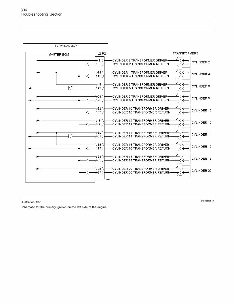
306Troubleshooting Section
g01065514Illustration 137Schematic for the primary ignition on the left side of the engine
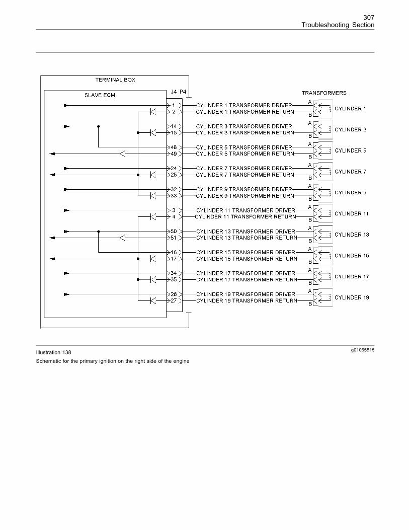
307Troubleshooting Section
g01065515Illustration 138Schematic for the primary ignition on the right side of the engine
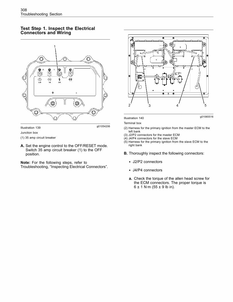
308Troubleshooting Section
Test Step 1. Inspect the ElectricalConnectors and Wiring
g01054206Illustration 139Junction box
(1) 35 amp circuit breaker
A. Set the engine control to the OFF/RESET mode.Switch 35 amp circuit breaker (1) to the OFFposition.
Note: For the following steps, refer toTroubleshooting, “Inspecting Electrical Connectors”.
g01065516Illustration 140
Terminal box(2) Harness for the primary ignition from the master ECM to the
left bank(3) J2/P2 connectors for the master ECM(4) J4/P4 connectors for the slave ECM(5) Harness for the primary ignition from the slave ECM to the
right bank
B. Thoroughly inspect the following connectors:
• J2/P2 connectors
• J4/P4 connectors
a. Check the torque of the allen head screw forthe ECM connectors. The proper torque is6 ± 1 N·m (55 ± 9 lb in).
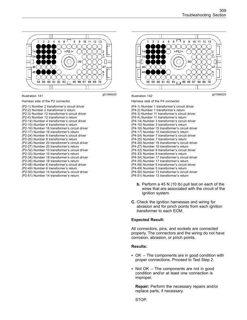
309Troubleshooting Section
g01066020Illustration 141Harness side of the P2 connector
(P2-1) Number 2 transformer’s circuit driver(P2-2) Number 2 transformer’s return(P2-3) Number 12 transformer’s circuit driver(P2-4) Number 12 transformer’s return(P2-14) Number 4 transformer’s circuit driver(P2-15) Number 4 transformer’s return(P2-16) Number 16 transformer’s circuit driver(P2-17) Number 16 transformer’s return(P2-24) Number 8 transformer’s circuit driver(P2-25) Number 8 transformer’s return(P2-26) Number 20 transformer’s circuit driver(P2-27) Number 20 transformer’s return(P2-32) Number 10 transformer’s circuit driver(P2-33) Number 10 transformer’s return(P2-34) Number 18 transformer’s circuit driver(P2-35) Number 18 transformer’s return(P2-48) Number 6 transformer’s circuit driver(P2-49) Number 6 transformer’s return(P2-50) Number 14 transformer’s circuit driver(P2-51) Number 14 transformer’s return
g01066020Illustration 142Harness side of the P4 connector
(P4-1) Number 1 transformer’s circuit driver(P4-2) Number 1 transformer’s return(P4-3) Number 11 transformer’s circuit driver(P4-4) Number 11 transformer’s return(P4-14) Number 3 transformer’s circuit driver(P4-15) Number 3 transformer’s return(P4-16) Number 15 transformer’s circuit driver(P4-17) Number 15 transformer’s return(P4-24) Number 7 transformer’s circuit driver(P4-25) Number 7 transformer’s return(P4-26) Number 19 transformer’s circuit driver(P4-27) Number 19 transformer’s return(P4-32) Number 9 transformer’s circuit driver(P4-33) Number 9 transformer’s return(P4-34) Number 17 transformer’s circuit driver(P4-35) Number 17 transformer’s return(P4-48) Number 5 transformer’s circuit driver(P4-49) Number 5 transformer’s return(P4-50) Number 13 transformer’s circuit driver(P4-51) Number 13 transformer’s return
b. Perform a 45 N (10 lb) pull test on each of thewires that are associated with the circuit of theignition system.
C. Check the ignition harnesses and wiring forabrasion and for pinch points from each ignitiontransformer to each ECM.
Expected Result:
All connectors, pins, and sockets are connectedproperly. The connectors and the wiring do not havecorrosion, abrasion, or pinch points.
Results:
• OK – The components are in good condition withproper connections. Proceed to Test Step 2.
• Not OK – The components are not in goodcondition and/or at least one connection isimproper.
Repair: Perform the necessary repairs and/orreplace parts, if necessary.
STOP.
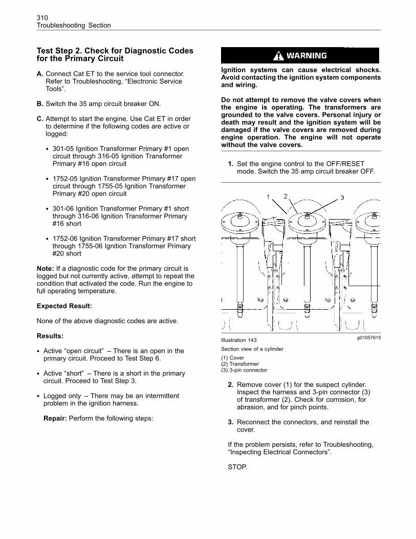
310Troubleshooting Section
Test Step 2. Check for Diagnostic Codesfor the Primary Circuit
A. Connect Cat ET to the service tool connector.Refer to Troubleshooting, “Electronic ServiceTools”.
B. Switch the 35 amp circuit breaker ON.
C. Attempt to start the engine. Use Cat ET in orderto determine if the following codes are active orlogged:
• 301-05 Ignition Transformer Primary #1 opencircuit through 316-05 Ignition TransformerPrimary #16 open circuit
• 1752-05 Ignition Transformer Primary #17 opencircuit through 1755-05 Ignition TransformerPrimary #20 open circuit
• 301-06 Ignition Transformer Primary #1 shortthrough 316-06 Ignition Transformer Primary#16 short
• 1752-06 Ignition Transformer Primary #17 shortthrough 1755-06 Ignition Transformer Primary#20 short
Note: If a diagnostic code for the primary circuit islogged but not currently active, attempt to repeat thecondition that activated the code. Run the engine tofull operating temperature.
Expected Result:
None of the above diagnostic codes are active.
Results:
• Active “open circuit” – There is an open in theprimary circuit. Proceed to Test Step 6.
• Active “short” – There is a short in the primarycircuit. Proceed to Test Step 3.
• Logged only – There may be an intermittentproblem in the ignition harness.
Repair: Perform the following steps:
Ignition systems can cause electrical shocks.Avoid contacting the ignition system componentsand wiring.
Do not attempt to remove the valve covers whenthe engine is operating. The transformers aregrounded to the valve covers. Personal injury ordeath may result and the ignition system will bedamaged if the valve covers are removed duringengine operation. The engine will not operatewithout the valve covers.
1. Set the engine control to the OFF/RESETmode. Switch the 35 amp circuit breaker OFF.
g01057615Illustration 143Section view of a cylinder(1) Cover(2) Transformer(3) 3-pin connector
2. Remove cover (1) for the suspect cylinder.Inspect the harness and 3-pin connector (3)of transformer (2). Check for corrosion, forabrasion, and for pinch points.
3. Reconnect the connectors, and reinstall thecover.
If the problem persists, refer to Troubleshooting,“Inspecting Electrical Connectors”.
STOP.
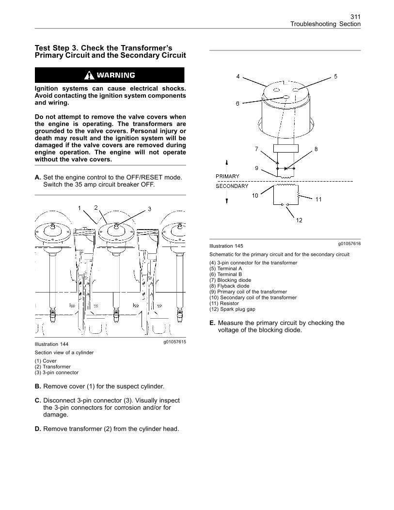
311Troubleshooting Section
Test Step 3. Check the Transformer’sPrimary Circuit and the Secondary Circuit
Ignition systems can cause electrical shocks.Avoid contacting the ignition system componentsand wiring.
Do not attempt to remove the valve covers whenthe engine is operating. The transformers aregrounded to the valve covers. Personal injury ordeath may result and the ignition system will bedamaged if the valve covers are removed duringengine operation. The engine will not operatewithout the valve covers.
A. Set the engine control to the OFF/RESET mode.Switch the 35 amp circuit breaker OFF.
g01057615Illustration 144Section view of a cylinder(1) Cover(2) Transformer(3) 3-pin connector
B. Remove cover (1) for the suspect cylinder.
C. Disconnect 3-pin connector (3). Visually inspectthe 3-pin connectors for corrosion and/or fordamage.
D. Remove transformer (2) from the cylinder head.
g01057616Illustration 145
Schematic for the primary circuit and for the secondary circuit(4) 3-pin connector for the transformer(5) Terminal A(6) Terminal B(7) Blocking diode(8) Flyback diode(9) Primary coil of the transformer(10) Secondary coil of the transformer(11) Resistor(12) Spark plug gap
E. Measure the primary circuit by checking thevoltage of the blocking diode.
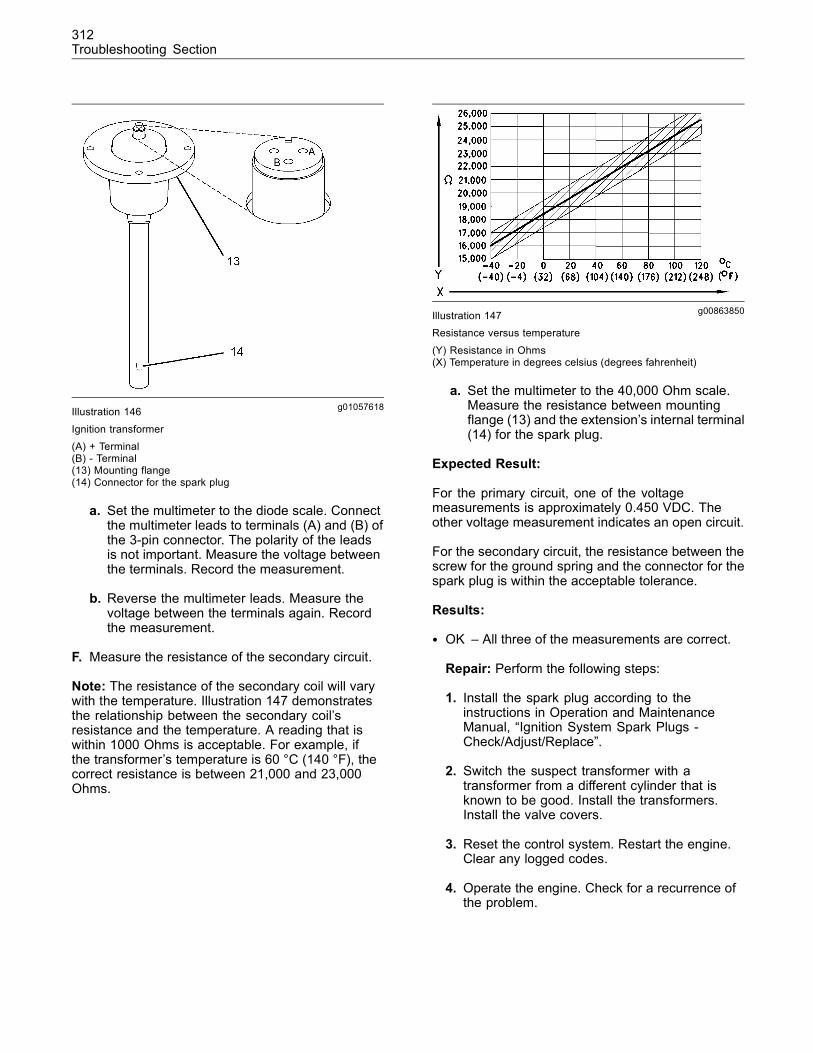
312Troubleshooting Section
g01057618Illustration 146
Ignition transformer(A) + Terminal(B) - Terminal(13) Mounting flange(14) Connector for the spark plug
a. Set the multimeter to the diode scale. Connectthe multimeter leads to terminals (A) and (B) ofthe 3-pin connector. The polarity of the leadsis not important. Measure the voltage betweenthe terminals. Record the measurement.
b. Reverse the multimeter leads. Measure thevoltage between the terminals again. Recordthe measurement.
F. Measure the resistance of the secondary circuit.
Note: The resistance of the secondary coil will varywith the temperature. Illustration 147 demonstratesthe relationship between the secondary coil’sresistance and the temperature. A reading that iswithin 1000 Ohms is acceptable. For example, ifthe transformer’s temperature is 60 °C (140 °F), thecorrect resistance is between 21,000 and 23,000Ohms.
g00863850Illustration 147Resistance versus temperature
(Y) Resistance in Ohms(X) Temperature in degrees celsius (degrees fahrenheit)
a. Set the multimeter to the 40,000 Ohm scale.Measure the resistance between mountingflange (13) and the extension’s internal terminal(14) for the spark plug.
Expected Result:
For the primary circuit, one of the voltagemeasurements is approximately 0.450 VDC. Theother voltage measurement indicates an open circuit.
For the secondary circuit, the resistance between thescrew for the ground spring and the connector for thespark plug is within the acceptable tolerance.
Results:
• OK – All three of the measurements are correct.
Repair: Perform the following steps:
1. Install the spark plug according to theinstructions in Operation and MaintenanceManual, “Ignition System Spark Plugs -Check/Adjust/Replace”.
2. Switch the suspect transformer with atransformer from a different cylinder that isknown to be good. Install the transformers.Install the valve covers.
3. Reset the control system. Restart the engine.Clear any logged codes.
4. Operate the engine. Check for a recurrence ofthe problem.
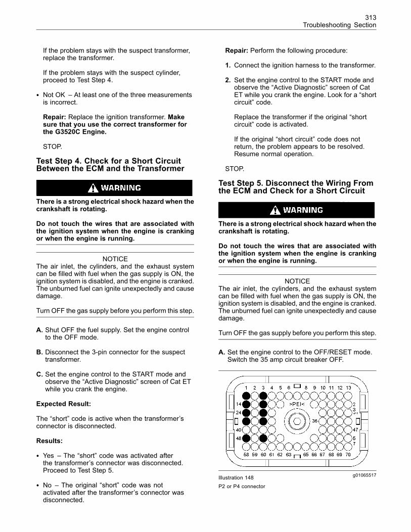
313Troubleshooting Section
If the problem stays with the suspect transformer,replace the transformer.
If the problem stays with the suspect cylinder,proceed to Test Step 4.
• Not OK – At least one of the three measurementsis incorrect.
Repair: Replace the ignition transformer. Makesure that you use the correct transformer forthe G3520C Engine.
STOP.
Test Step 4. Check for a Short CircuitBetween the ECM and the Transformer
There is a strong electrical shock hazard when thecrankshaft is rotating.
Do not touch the wires that are associated withthe ignition system when the engine is crankingor when the engine is running.
NOTICEThe air inlet, the cylinders, and the exhaust systemcan be filled with fuel when the gas supply is ON, theignition system is disabled, and the engine is cranked.The unburned fuel can ignite unexpectedly and causedamage.
Turn OFF the gas supply before you perform this step.
A. Shut OFF the fuel supply. Set the engine controlto the OFF mode.
B. Disconnect the 3-pin connector for the suspecttransformer.
C. Set the engine control to the START mode andobserve the “Active Diagnostic” screen of Cat ETwhile you crank the engine.
Expected Result:
The “short” code is active when the transformer’sconnector is disconnected.
Results:
• Yes – The “short” code was activated afterthe transformer’s connector was disconnected.Proceed to Test Step 5.
• No – The original “short” code was notactivated after the transformer’s connector wasdisconnected.
Repair: Perform the following procedure:
1. Connect the ignition harness to the transformer.
2. Set the engine control to the START mode andobserve the “Active Diagnostic” screen of CatET while you crank the engine. Look for a “shortcircuit” code.
Replace the transformer if the original “shortcircuit” code is activated.
If the original “short circuit” code does notreturn, the problem appears to be resolved.Resume normal operation.
STOP.
Test Step 5. Disconnect the Wiring Fromthe ECM and Check for a Short Circuit
There is a strong electrical shock hazard when thecrankshaft is rotating.
Do not touch the wires that are associated withthe ignition system when the engine is crankingor when the engine is running.
NOTICEThe air inlet, the cylinders, and the exhaust systemcan be filled with fuel when the gas supply is ON, theignition system is disabled, and the engine is cranked.The unburned fuel can ignite unexpectedly and causedamage.
Turn OFF the gas supply before you perform this step.
A. Set the engine control to the OFF/RESET mode.Switch the 35 amp circuit breaker OFF.
g01065517Illustration 148P2 or P4 connector
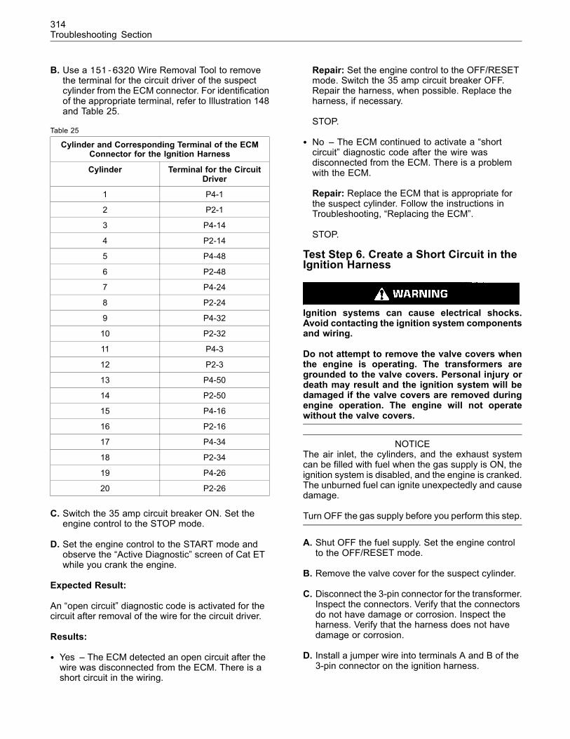
314Troubleshooting Section
B. Use a 151-6320 Wire Removal Tool to removethe terminal for the circuit driver of the suspectcylinder from the ECM connector. For identificationof the appropriate terminal, refer to Illustration 148and Table 25.
Table 25
Cylinder and Corresponding Terminal of the ECMConnector for the Ignition Harness
Cylinder Terminal for the CircuitDriver
1 P4-1
2 P2-1
3 P4-14
4 P2-14
5 P4-48
6 P2-48
7 P4-24
8 P2-24
9 P4-32
10 P2-32
11 P4-3
12 P2-3
13 P4-50
14 P2-50
15 P4-16
16 P2-16
17 P4-34
18 P2-34
19 P4-26
20 P2-26
C. Switch the 35 amp circuit breaker ON. Set theengine control to the STOP mode.
D. Set the engine control to the START mode andobserve the “Active Diagnostic” screen of Cat ETwhile you crank the engine.
Expected Result:
An “open circuit” diagnostic code is activated for thecircuit after removal of the wire for the circuit driver.
Results:
• Yes – The ECM detected an open circuit after thewire was disconnected from the ECM. There is ashort circuit in the wiring.
Repair: Set the engine control to the OFF/RESETmode. Switch the 35 amp circuit breaker OFF.Repair the harness, when possible. Replace theharness, if necessary.
STOP.
• No – The ECM continued to activate a “shortcircuit” diagnostic code after the wire wasdisconnected from the ECM. There is a problemwith the ECM.
Repair: Replace the ECM that is appropriate forthe suspect cylinder. Follow the instructions inTroubleshooting, “Replacing the ECM”.
STOP.
Test Step 6. Create a Short Circuit in theIgnition Harness
Ignition systems can cause electrical shocks.Avoid contacting the ignition system componentsand wiring.
Do not attempt to remove the valve covers whenthe engine is operating. The transformers aregrounded to the valve covers. Personal injury ordeath may result and the ignition system will bedamaged if the valve covers are removed duringengine operation. The engine will not operatewithout the valve covers.
NOTICEThe air inlet, the cylinders, and the exhaust systemcan be filled with fuel when the gas supply is ON, theignition system is disabled, and the engine is cranked.The unburned fuel can ignite unexpectedly and causedamage.
Turn OFF the gas supply before you perform this step.
A. Shut OFF the fuel supply. Set the engine controlto the OFF/RESET mode.
B. Remove the valve cover for the suspect cylinder.
C. Disconnect the 3-pin connector for the transformer.Inspect the connectors. Verify that the connectorsdo not have damage or corrosion. Inspect theharness. Verify that the harness does not havedamage or corrosion.
D. Install a jumper wire into terminals A and B of the3-pin connector on the ignition harness.
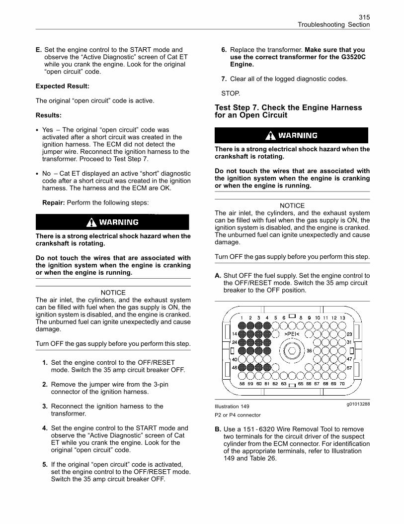
315Troubleshooting Section
E. Set the engine control to the START mode andobserve the “Active Diagnostic” screen of Cat ETwhile you crank the engine. Look for the original“open circuit” code.
Expected Result:
The original “open circuit” code is active.
Results:
• Yes – The original “open circuit” code wasactivated after a short circuit was created in theignition harness. The ECM did not detect thejumper wire. Reconnect the ignition harness to thetransformer. Proceed to Test Step 7.
• No – Cat ET displayed an active “short” diagnosticcode after a short circuit was created in the ignitionharness. The harness and the ECM are OK.
Repair: Perform the following steps:
There is a strong electrical shock hazard when thecrankshaft is rotating.
Do not touch the wires that are associated withthe ignition system when the engine is crankingor when the engine is running.
NOTICEThe air inlet, the cylinders, and the exhaust systemcan be filled with fuel when the gas supply is ON, theignition system is disabled, and the engine is cranked.The unburned fuel can ignite unexpectedly and causedamage.
Turn OFF the gas supply before you perform this step.
1. Set the engine control to the OFF/RESETmode. Switch the 35 amp circuit breaker OFF.
2. Remove the jumper wire from the 3-pinconnector of the ignition harness.
3. Reconnect the ignition harness to thetransformer.
4. Set the engine control to the START mode andobserve the “Active Diagnostic” screen of CatET while you crank the engine. Look for theoriginal “open circuit” code.
5. If the original “open circuit” code is activated,set the engine control to the OFF/RESET mode.Switch the 35 amp circuit breaker OFF.
6. Replace the transformer. Make sure that youuse the correct transformer for the G3520CEngine.
7. Clear all of the logged diagnostic codes.
STOP.
Test Step 7. Check the Engine Harnessfor an Open Circuit
There is a strong electrical shock hazard when thecrankshaft is rotating.
Do not touch the wires that are associated withthe ignition system when the engine is crankingor when the engine is running.
NOTICEThe air inlet, the cylinders, and the exhaust systemcan be filled with fuel when the gas supply is ON, theignition system is disabled, and the engine is cranked.The unburned fuel can ignite unexpectedly and causedamage.
Turn OFF the gas supply before you perform this step.
A. Shut OFF the fuel supply. Set the engine control tothe OFF/RESET mode. Switch the 35 amp circuitbreaker to the OFF position.
g01013288Illustration 149P2 or P4 connector
B. Use a 151-6320 Wire Removal Tool to removetwo terminals for the circuit driver of the suspectcylinder from the ECM connector. For identificationof the appropriate terminals, refer to Illustration149 and Table 26.
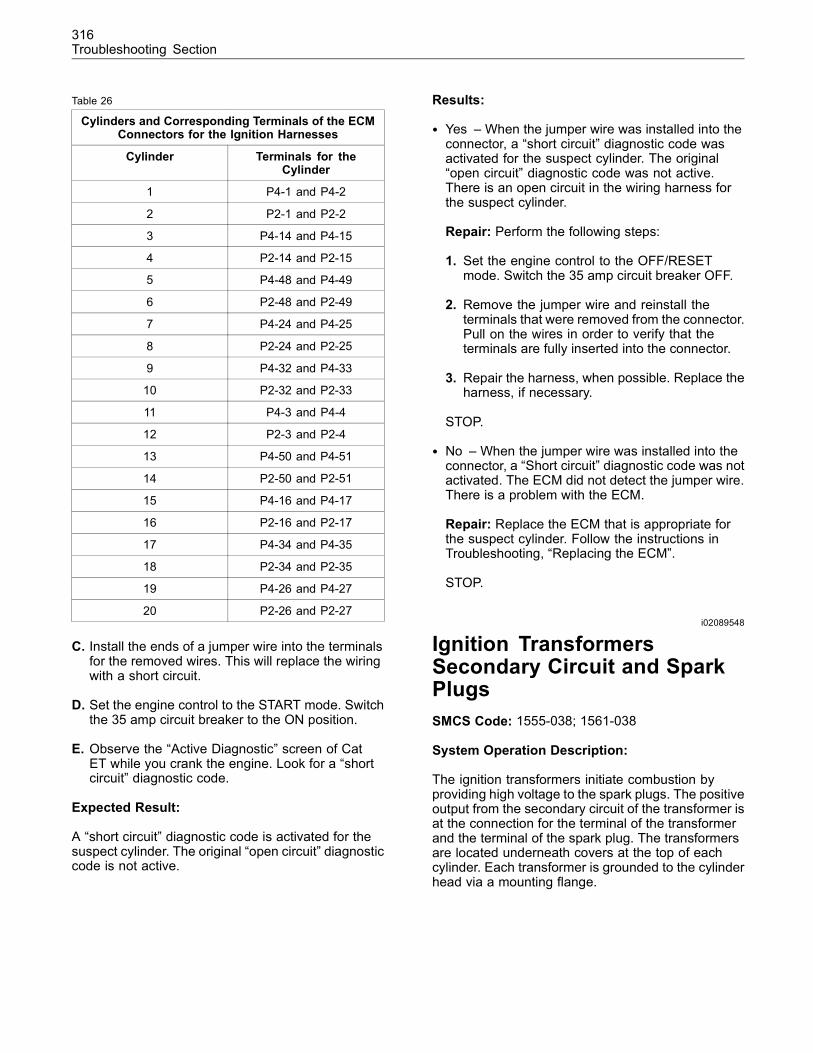
316Troubleshooting Section
Table 26
Cylinders and Corresponding Terminals of the ECMConnectors for the Ignition Harnesses
Cylinder Terminals for theCylinder
1 P4-1 and P4-2
2 P2-1 and P2-2
3 P4-14 and P4-15
4 P2-14 and P2-15
5 P4-48 and P4-49
6 P2-48 and P2-49
7 P4-24 and P4-25
8 P2-24 and P2-25
9 P4-32 and P4-33
10 P2-32 and P2-33
11 P4-3 and P4-4
12 P2-3 and P2-4
13 P4-50 and P4-51
14 P2-50 and P2-51
15 P4-16 and P4-17
16 P2-16 and P2-17
17 P4-34 and P4-35
18 P2-34 and P2-35
19 P4-26 and P4-27
20 P2-26 and P2-27
C. Install the ends of a jumper wire into the terminalsfor the removed wires. This will replace the wiringwith a short circuit.
D. Set the engine control to the START mode. Switchthe 35 amp circuit breaker to the ON position.
E. Observe the “Active Diagnostic” screen of CatET while you crank the engine. Look for a “shortcircuit” diagnostic code.
Expected Result:
A “short circuit” diagnostic code is activated for thesuspect cylinder. The original “open circuit” diagnosticcode is not active.
Results:
• Yes – When the jumper wire was installed into theconnector, a “short circuit” diagnostic code wasactivated for the suspect cylinder. The original“open circuit” diagnostic code was not active.There is an open circuit in the wiring harness forthe suspect cylinder.
Repair: Perform the following steps:
1. Set the engine control to the OFF/RESETmode. Switch the 35 amp circuit breaker OFF.
2. Remove the jumper wire and reinstall theterminals that were removed from the connector.Pull on the wires in order to verify that theterminals are fully inserted into the connector.
3. Repair the harness, when possible. Replace theharness, if necessary.
STOP.
• No – When the jumper wire was installed into theconnector, a “Short circuit” diagnostic code was notactivated. The ECM did not detect the jumper wire.There is a problem with the ECM.
Repair: Replace the ECM that is appropriate forthe suspect cylinder. Follow the instructions inTroubleshooting, “Replacing the ECM”.
STOP.
i02089548
Ignition TransformersSecondary Circuit and SparkPlugsSMCS Code: 1555-038; 1561-038
System Operation Description:
The ignition transformers initiate combustion byproviding high voltage to the spark plugs. The positiveoutput from the secondary circuit of the transformer isat the connection for the terminal of the transformerand the terminal of the spark plug. The transformersare located underneath covers at the top of eachcylinder. Each transformer is grounded to the cylinderhead via a mounting flange.
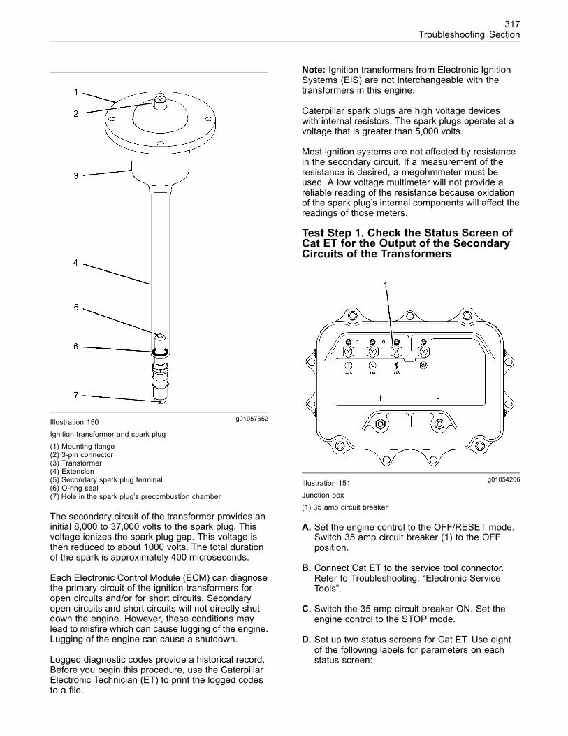
317Troubleshooting Section
g01057652Illustration 150Ignition transformer and spark plug(1) Mounting flange(2) 3-pin connector(3) Transformer(4) Extension(5) Secondary spark plug terminal(6) O-ring seal(7) Hole in the spark plug’s precombustion chamber
The secondary circuit of the transformer provides aninitial 8,000 to 37,000 volts to the spark plug. Thisvoltage ionizes the spark plug gap. This voltage isthen reduced to about 1000 volts. The total durationof the spark is approximately 400 microseconds.
Each Electronic Control Module (ECM) can diagnosethe primary circuit of the ignition transformers foropen circuits and/or for short circuits. Secondaryopen circuits and short circuits will not directly shutdown the engine. However, these conditions maylead to misfire which can cause lugging of the engine.Lugging of the engine can cause a shutdown.
Logged diagnostic codes provide a historical record.Before you begin this procedure, use the CaterpillarElectronic Technician (ET) to print the logged codesto a file.
Note: Ignition transformers from Electronic IgnitionSystems (EIS) are not interchangeable with thetransformers in this engine.
Caterpillar spark plugs are high voltage deviceswith internal resistors. The spark plugs operate at avoltage that is greater than 5,000 volts.
Most ignition systems are not affected by resistancein the secondary circuit. If a measurement of theresistance is desired, a megohmmeter must beused. A low voltage multimeter will not provide areliable reading of the resistance because oxidationof the spark plug’s internal components will affect thereadings of those meters.
Test Step 1. Check the Status Screen ofCat ET for the Output of the SecondaryCircuits of the Transformers
g01054206Illustration 151Junction box(1) 35 amp circuit breaker
A. Set the engine control to the OFF/RESET mode.Switch 35 amp circuit breaker (1) to the OFFposition.
B. Connect Cat ET to the service tool connector.Refer to Troubleshooting, “Electronic ServiceTools”.
C. Switch the 35 amp circuit breaker ON. Set theengine control to the STOP mode.
D. Set up two status screens for Cat ET. Use eightof the following labels for parameters on eachstatus screen:
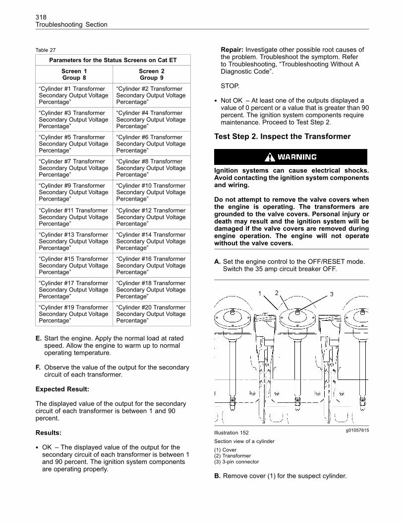
318Troubleshooting Section
Table 27
Parameters for the Status Screens on Cat ET
Screen 1Group 8
Screen 2Group 9
“Cylinder #1 TransformerSecondary Output VoltagePercentage”
“Cylinder #2 TransformerSecondary Output VoltagePercentage”
“Cylinder #3 TransformerSecondary Output VoltagePercentage”
“Cylinder #4 TransformerSecondary Output VoltagePercentage”
“Cylinder #5 TransformerSecondary Output VoltagePercentage”
“Cylinder #6 TransformerSecondary Output VoltagePercentage”
“Cylinder #7 TransformerSecondary Output VoltagePercentage”
“Cylinder #8 TransformerSecondary Output VoltagePercentage”
“Cylinder #9 TransformerSecondary Output VoltagePercentage”
“Cylinder #10 TransformerSecondary Output VoltagePercentage”
“Cylinder #11 TransformerSecondary Output VoltagePercentage”
“Cylinder #12 TransformerSecondary Output VoltagePercentage”
“Cylinder #13 TransformerSecondary Output VoltagePercentage”
“Cylinder #14 TransformerSecondary Output VoltagePercentage”
“Cylinder #15 TransformerSecondary Output VoltagePercentage”
“Cylinder #16 TransformerSecondary Output VoltagePercentage”
“Cylinder #17 TransformerSecondary Output VoltagePercentage”
“Cylinder #18 TransformerSecondary Output VoltagePercentage”
“Cylinder #19 TransformerSecondary Output VoltagePercentage”
“Cylinder #20 TransformerSecondary Output VoltagePercentage”
E. Start the engine. Apply the normal load at ratedspeed. Allow the engine to warm up to normaloperating temperature.
F. Observe the value of the output for the secondarycircuit of each transformer.
Expected Result:
The displayed value of the output for the secondarycircuit of each transformer is between 1 and 90percent.
Results:
• OK – The displayed value of the output for thesecondary circuit of each transformer is between 1and 90 percent. The ignition system componentsare operating properly.
Repair: Investigate other possible root causes ofthe problem. Troubleshoot the symptom. Referto Troubleshooting, “Troubleshooting Without ADiagnostic Code”.
STOP.
• Not OK – At least one of the outputs displayed avalue of 0 percent or a value that is greater than 90percent. The ignition system components requiremaintenance. Proceed to Test Step 2.
Test Step 2. Inspect the Transformer
Ignition systems can cause electrical shocks.Avoid contacting the ignition system componentsand wiring.
Do not attempt to remove the valve covers whenthe engine is operating. The transformers aregrounded to the valve covers. Personal injury ordeath may result and the ignition system will bedamaged if the valve covers are removed duringengine operation. The engine will not operatewithout the valve covers.
A. Set the engine control to the OFF/RESET mode.Switch the 35 amp circuit breaker OFF.
g01057615Illustration 152Section view of a cylinder(1) Cover(2) Transformer(3) 3-pin connector
B. Remove cover (1) for the suspect cylinder.
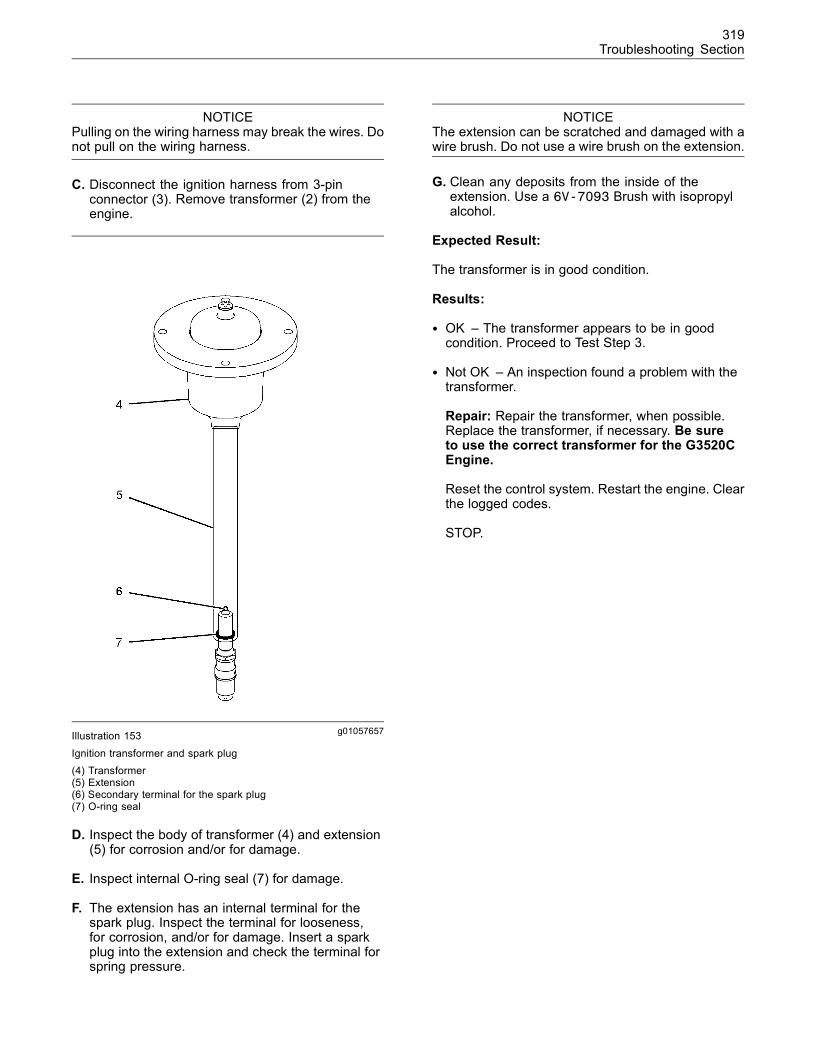
319Troubleshooting Section
NOTICEPulling on the wiring harness may break the wires. Donot pull on the wiring harness.
C. Disconnect the ignition harness from 3-pinconnector (3). Remove transformer (2) from theengine.
g01057657Illustration 153
Ignition transformer and spark plug(4) Transformer(5) Extension(6) Secondary terminal for the spark plug(7) O-ring seal
D. Inspect the body of transformer (4) and extension(5) for corrosion and/or for damage.
E. Inspect internal O-ring seal (7) for damage.
F. The extension has an internal terminal for thespark plug. Inspect the terminal for looseness,for corrosion, and/or for damage. Insert a sparkplug into the extension and check the terminal forspring pressure.
NOTICEThe extension can be scratched and damaged with awire brush. Do not use a wire brush on the extension.
G. Clean any deposits from the inside of theextension. Use a 6V-7093 Brush with isopropylalcohol.
Expected Result:
The transformer is in good condition.
Results:
• OK – The transformer appears to be in goodcondition. Proceed to Test Step 3.
• Not OK – An inspection found a problem with thetransformer.
Repair: Repair the transformer, when possible.Replace the transformer, if necessary. Be sureto use the correct transformer for the G3520CEngine.
Reset the control system. Restart the engine. Clearthe logged codes.
STOP.
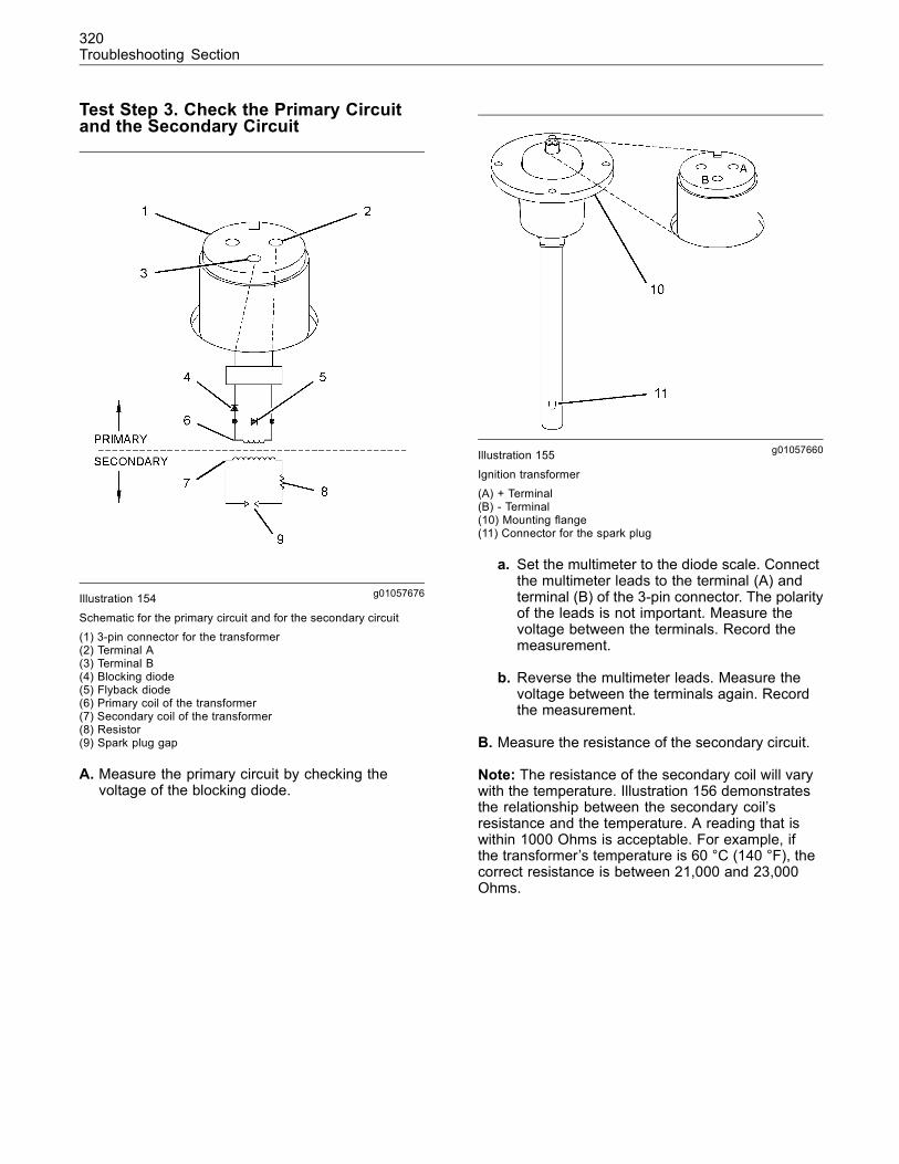
320Troubleshooting Section
Test Step 3. Check the Primary Circuitand the Secondary Circuit
g01057676Illustration 154
Schematic for the primary circuit and for the secondary circuit(1) 3-pin connector for the transformer(2) Terminal A(3) Terminal B(4) Blocking diode(5) Flyback diode(6) Primary coil of the transformer(7) Secondary coil of the transformer(8) Resistor(9) Spark plug gap
A. Measure the primary circuit by checking thevoltage of the blocking diode.
g01057660Illustration 155
Ignition transformer(A) + Terminal(B) - Terminal(10) Mounting flange(11) Connector for the spark plug
a. Set the multimeter to the diode scale. Connectthe multimeter leads to the terminal (A) andterminal (B) of the 3-pin connector. The polarityof the leads is not important. Measure thevoltage between the terminals. Record themeasurement.
b. Reverse the multimeter leads. Measure thevoltage between the terminals again. Recordthe measurement.
B. Measure the resistance of the secondary circuit.
Note: The resistance of the secondary coil will varywith the temperature. Illustration 156 demonstratesthe relationship between the secondary coil’sresistance and the temperature. A reading that iswithin 1000 Ohms is acceptable. For example, ifthe transformer’s temperature is 60 °C (140 °F), thecorrect resistance is between 21,000 and 23,000Ohms.
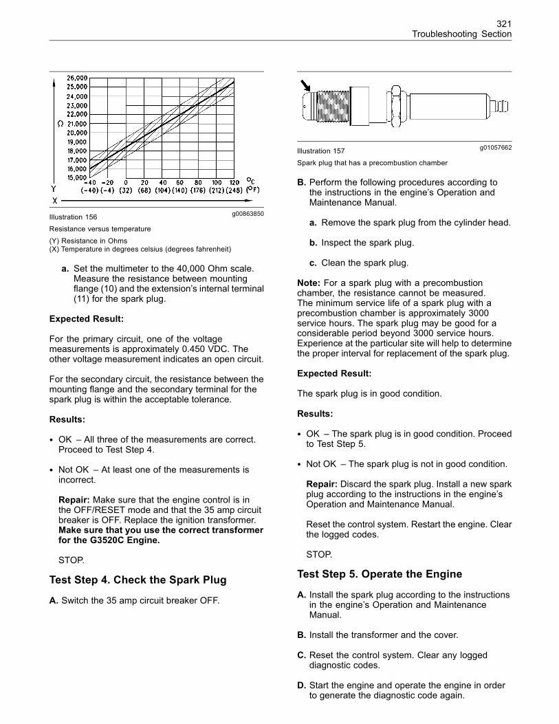
321Troubleshooting Section
g00863850Illustration 156Resistance versus temperature
(Y) Resistance in Ohms(X) Temperature in degrees celsius (degrees fahrenheit)
a. Set the multimeter to the 40,000 Ohm scale.Measure the resistance between mountingflange (10) and the extension’s internal terminal(11) for the spark plug.
Expected Result:
For the primary circuit, one of the voltagemeasurements is approximately 0.450 VDC. Theother voltage measurement indicates an open circuit.
For the secondary circuit, the resistance between themounting flange and the secondary terminal for thespark plug is within the acceptable tolerance.
Results:
• OK – All three of the measurements are correct.Proceed to Test Step 4.
• Not OK – At least one of the measurements isincorrect.
Repair: Make sure that the engine control is inthe OFF/RESET mode and that the 35 amp circuitbreaker is OFF. Replace the ignition transformer.Make sure that you use the correct transformerfor the G3520C Engine.
STOP.
Test Step 4. Check the Spark Plug
A. Switch the 35 amp circuit breaker OFF.
g01057662Illustration 157Spark plug that has a precombustion chamber
B. Perform the following procedures according tothe instructions in the engine’s Operation andMaintenance Manual.
a. Remove the spark plug from the cylinder head.
b. Inspect the spark plug.
c. Clean the spark plug.
Note: For a spark plug with a precombustionchamber, the resistance cannot be measured.The minimum service life of a spark plug with aprecombustion chamber is approximately 3000service hours. The spark plug may be good for aconsiderable period beyond 3000 service hours.Experience at the particular site will help to determinethe proper interval for replacement of the spark plug.
Expected Result:
The spark plug is in good condition.
Results:
• OK – The spark plug is in good condition. Proceedto Test Step 5.
• Not OK – The spark plug is not in good condition.
Repair: Discard the spark plug. Install a new sparkplug according to the instructions in the engine’sOperation and Maintenance Manual.
Reset the control system. Restart the engine. Clearthe logged codes.
STOP.
Test Step 5. Operate the Engine
A. Install the spark plug according to the instructionsin the engine’s Operation and MaintenanceManual.
B. Install the transformer and the cover.
C. Reset the control system. Clear any loggeddiagnostic codes.
D. Start the engine and operate the engine in orderto generate the diagnostic code again.
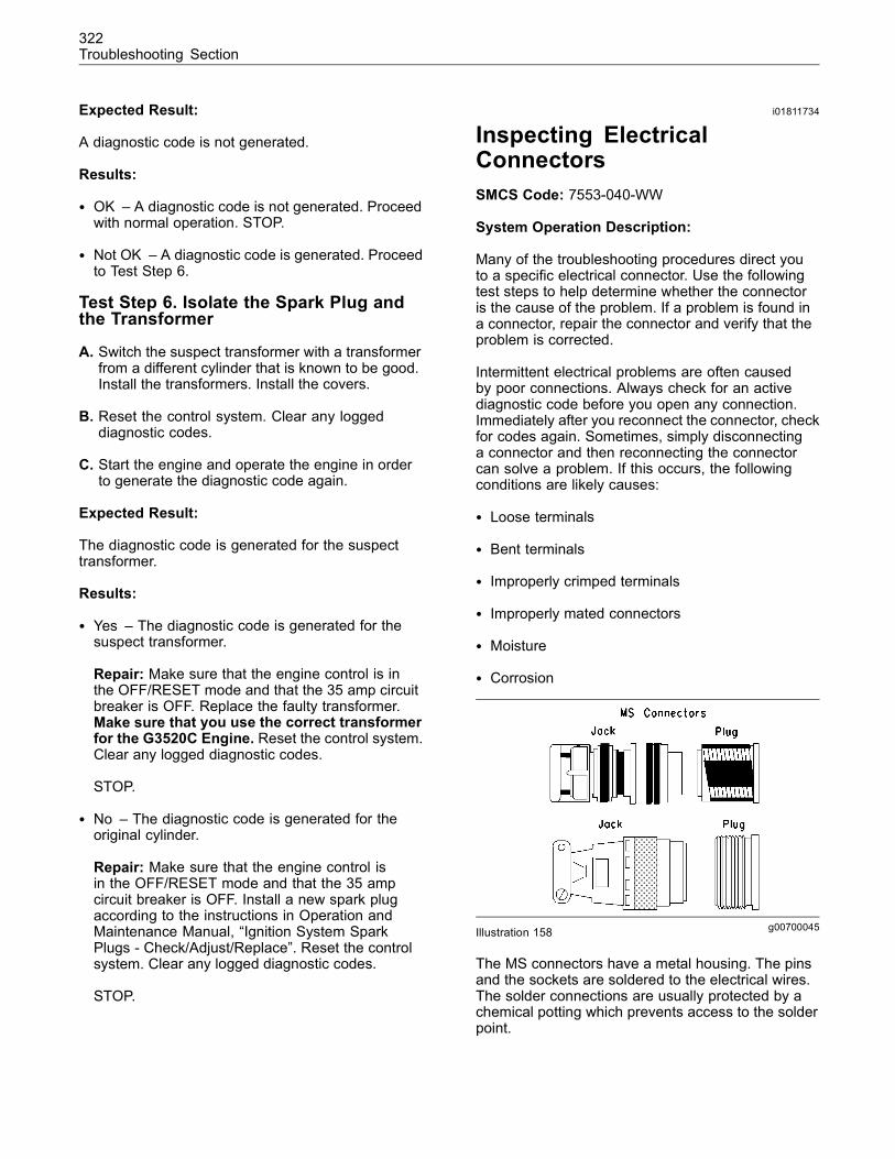
322Troubleshooting Section
Expected Result:
A diagnostic code is not generated.
Results:
• OK – A diagnostic code is not generated. Proceedwith normal operation. STOP.
• Not OK – A diagnostic code is generated. Proceedto Test Step 6.
Test Step 6. Isolate the Spark Plug andthe Transformer
A. Switch the suspect transformer with a transformerfrom a different cylinder that is known to be good.Install the transformers. Install the covers.
B. Reset the control system. Clear any loggeddiagnostic codes.
C. Start the engine and operate the engine in orderto generate the diagnostic code again.
Expected Result:
The diagnostic code is generated for the suspecttransformer.
Results:
• Yes – The diagnostic code is generated for thesuspect transformer.
Repair: Make sure that the engine control is inthe OFF/RESET mode and that the 35 amp circuitbreaker is OFF. Replace the faulty transformer.Make sure that you use the correct transformerfor the G3520C Engine. Reset the control system.Clear any logged diagnostic codes.
STOP.
• No – The diagnostic code is generated for theoriginal cylinder.
Repair: Make sure that the engine control isin the OFF/RESET mode and that the 35 ampcircuit breaker is OFF. Install a new spark plugaccording to the instructions in Operation andMaintenance Manual, “Ignition System SparkPlugs - Check/Adjust/Replace”. Reset the controlsystem. Clear any logged diagnostic codes.
STOP.
i01811734
Inspecting ElectricalConnectorsSMCS Code: 7553-040-WW
System Operation Description:
Many of the troubleshooting procedures direct youto a specific electrical connector. Use the followingtest steps to help determine whether the connectoris the cause of the problem. If a problem is found ina connector, repair the connector and verify that theproblem is corrected.
Intermittent electrical problems are often causedby poor connections. Always check for an activediagnostic code before you open any connection.Immediately after you reconnect the connector, checkfor codes again. Sometimes, simply disconnectinga connector and then reconnecting the connectorcan solve a problem. If this occurs, the followingconditions are likely causes:
• Loose terminals
• Bent terminals
• Improperly crimped terminals
• Improperly mated connectors
• Moisture
• Corrosion
g00700045Illustration 158
The MS connectors have a metal housing. The pinsand the sockets are soldered to the electrical wires.The solder connections are usually protected by achemical potting which prevents access to the solderpoint.
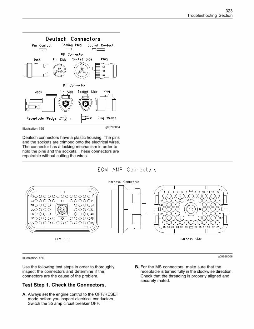
323Troubleshooting Section
g00700064Illustration 159
Deutsch connectors have a plastic housing. The pinsand the sockets are crimped onto the electrical wires.The connector has a locking mechanism in order tohold the pins and the sockets. These connectors arerepairable without cutting the wires.
g00928006Illustration 160
Use the following test steps in order to thoroughlyinspect the connectors and determine if theconnectors are the cause of the problem.
Test Step 1. Check the Connectors.
A. Always set the engine control to the OFF/RESETmode before you inspect electrical conductors.Switch the 35 amp circuit breaker OFF.
B. For the MS connectors, make sure that thereceptacle is turned fully in the clockwise direction.Check that the threading is properly aligned andsecurely mated.
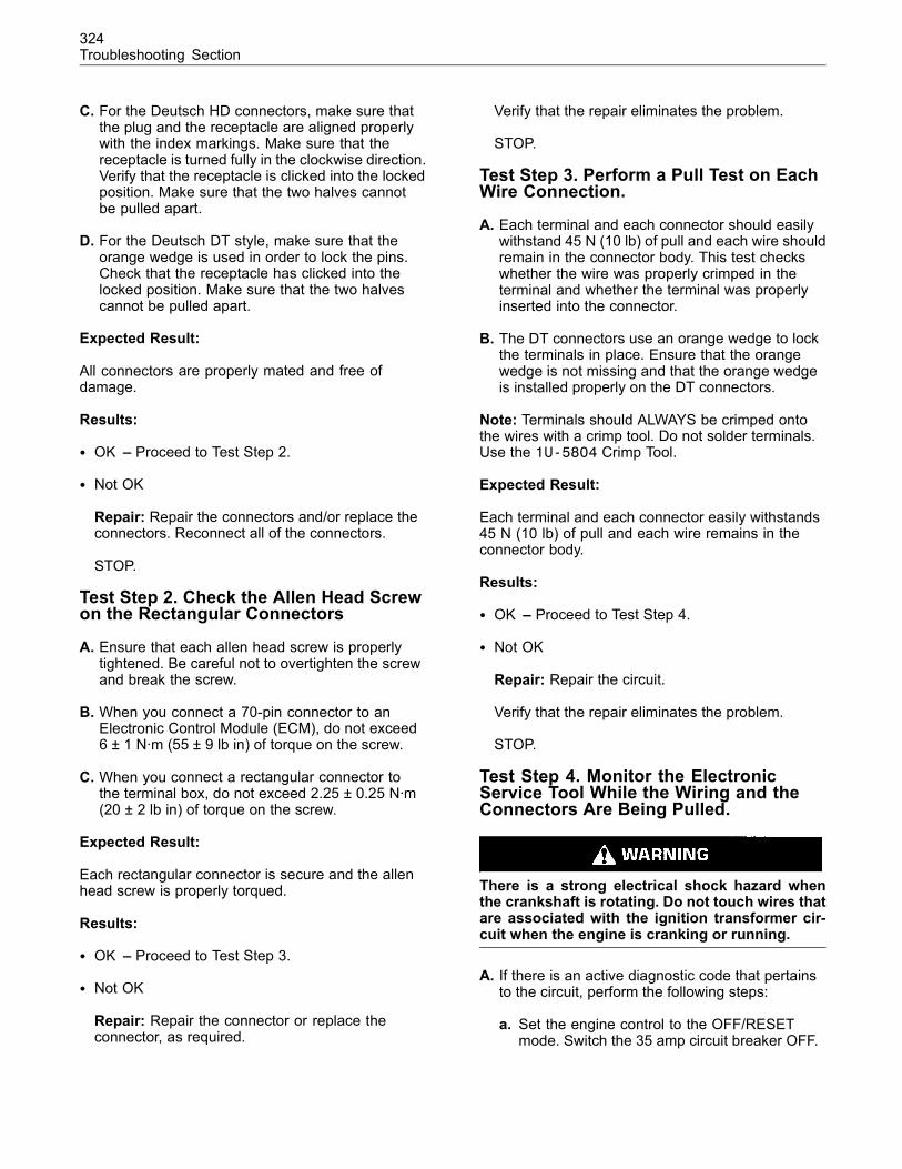
324Troubleshooting Section
C. For the Deutsch HD connectors, make sure thatthe plug and the receptacle are aligned properlywith the index markings. Make sure that thereceptacle is turned fully in the clockwise direction.Verify that the receptacle is clicked into the lockedposition. Make sure that the two halves cannotbe pulled apart.
D. For the Deutsch DT style, make sure that theorange wedge is used in order to lock the pins.Check that the receptacle has clicked into thelocked position. Make sure that the two halvescannot be pulled apart.
Expected Result:
All connectors are properly mated and free ofdamage.
Results:
• OK – Proceed to Test Step 2.
• Not OK
Repair: Repair the connectors and/or replace theconnectors. Reconnect all of the connectors.
STOP.
Test Step 2. Check the Allen Head Screwon the Rectangular Connectors
A. Ensure that each allen head screw is properlytightened. Be careful not to overtighten the screwand break the screw.
B. When you connect a 70-pin connector to anElectronic Control Module (ECM), do not exceed6 ± 1 N·m (55 ± 9 lb in) of torque on the screw.
C. When you connect a rectangular connector tothe terminal box, do not exceed 2.25 ± 0.25 N·m(20 ± 2 lb in) of torque on the screw.
Expected Result:
Each rectangular connector is secure and the allenhead screw is properly torqued.
Results:
• OK – Proceed to Test Step 3.
• Not OK
Repair: Repair the connector or replace theconnector, as required.
Verify that the repair eliminates the problem.
STOP.
Test Step 3. Perform a Pull Test on EachWire Connection.
A. Each terminal and each connector should easilywithstand 45 N (10 lb) of pull and each wire shouldremain in the connector body. This test checkswhether the wire was properly crimped in theterminal and whether the terminal was properlyinserted into the connector.
B. The DT connectors use an orange wedge to lockthe terminals in place. Ensure that the orangewedge is not missing and that the orange wedgeis installed properly on the DT connectors.
Note: Terminals should ALWAYS be crimped ontothe wires with a crimp tool. Do not solder terminals.Use the 1U-5804 Crimp Tool.
Expected Result:
Each terminal and each connector easily withstands45 N (10 lb) of pull and each wire remains in theconnector body.
Results:
• OK – Proceed to Test Step 4.
• Not OK
Repair: Repair the circuit.
Verify that the repair eliminates the problem.
STOP.
Test Step 4. Monitor the ElectronicService Tool While the Wiring and theConnectors Are Being Pulled.
There is a strong electrical shock hazard whenthe crankshaft is rotating. Do not touch wires thatare associated with the ignition transformer cir-cuit when the engine is cranking or running.
A. If there is an active diagnostic code that pertainsto the circuit, perform the following steps:
a. Set the engine control to the OFF/RESETmode. Switch the 35 amp circuit breaker OFF.
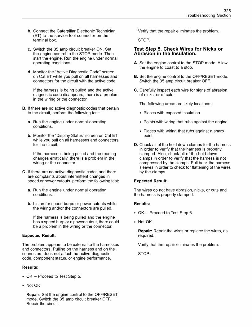
325Troubleshooting Section
b. Connect the Caterpillar Electronic Technician(ET) to the service tool connector on theterminal box.
c. Switch the 35 amp circuit breaker ON. Setthe engine control to the STOP mode. Thenstart the engine. Run the engine under normaloperating conditions.
d. Monitor the “Active Diagnostic Code” screenon Cat ET while you pull on all harnesses andconnectors for the circuit with the active code.
If the harness is being pulled and the activediagnostic code disappears, there is a problemin the wiring or the connector.
B. If there are no active diagnostic codes that pertainto the circuit, perform the following test:
a. Run the engine under normal operatingconditions.
b. Monitor the “Display Status” screen on Cat ETwhile you pull on all harnesses and connectorsfor the circuit.
If the harness is being pulled and the readingchanges erratically, there is a problem in thewiring or the connector.
C. If there are no active diagnostic codes and thereare complaints about intermittent changes inspeed or power cutouts, perform the following test:
a. Run the engine under normal operatingconditions.
b. Listen for speed burps or power cutouts whilethe wiring and/or the connectors are pulled.
If the harness is being pulled and the enginehas a speed burp or a power cutout, there couldbe a problem in the wiring or the connector.
Expected Result:
The problem appears to be external to the harnessesand connectors. Pulling on the harness and on theconnectors does not affect the active diagnosticcode, component status, or engine performance.
Results:
• OK – Proceed to Test Step 5.
• Not OK
Repair: Set the engine control to the OFF/RESETmode. Switch the 35 amp circuit breaker OFF.Repair the circuit.
Verify that the repair eliminates the problem.
STOP.
Test Step 5. Check Wires for Nicks orAbrasion in the Insulation.
A. Set the engine control to the STOP mode. Allowthe engine to coast to a stop.
B. Set the engine control to the OFF/RESET mode.Switch the 35 amp circuit breaker OFF.
C. Carefully inspect each wire for signs of abrasion,of nicks, or of cuts.
The following areas are likely locations:
• Places with exposed insulation
• Points with wiring that rubs against the engine
• Places with wiring that rubs against a sharppoint
D. Check all of the hold down clamps for the harnessin order to verify that the harness is properlyclamped. Also, check all of the hold downclamps in order to verify that the harness is notcompressed by the clamps. Pull back the harnesssleeves in order to check for flattening of the wiresby the clamps.
Expected Result:
The wires do not have abrasion, nicks, or cuts andthe harness is properly clamped.
Results:
• OK – Proceed to Test Step 6.
• Not OK
Repair: Repair the wires or replace the wires, asrequired.
Verify that the repair eliminates the problem.
STOP.
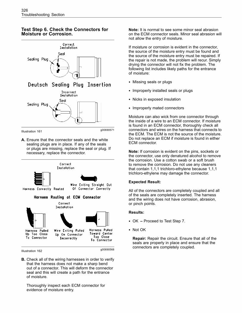
326Troubleshooting Section
Test Step 6. Check the Connectors forMoisture or Corrosion.
g00690571Illustration 161
A. Ensure that the connector seals and the whitesealing plugs are in place. If any of the sealsor plugs are missing, replace the seal or plug. Ifnecessary, replace the connector.
g00690568Illustration 162
B. Check all of the wiring harnesses in order to verifythat the harness does not make a sharp bendout of a connector. This will deform the connectorseal and this will create a path for the entranceof moisture.
Thoroughly inspect each ECM connector forevidence of moisture entry.
Note: It is normal to see some minor seal abrasionon the ECM connector seals. Minor seal abrasion willnot allow the entry of moisture.
If moisture or corrosion is evident in the connector,the source of the moisture entry must be found andthe source of the moisture entry must be repaired. Ifthe repair is not made, the problem will recur. Simplydrying the connector will not fix the problem. Thefollowing list includes likely paths for the entranceof moisture:
• Missing seals or plugs
• Improperly installed seals or plugs
• Nicks in exposed insulation
• Improperly mated connectors
Moisture can also wick from one connector throughthe inside of a wire to an ECM connector. If moistureis found in an ECM connector, thoroughly check allconnectors and wires on the harness that connects tothe ECM. The ECM is not the source of the moisture.Do not replace an ECM if moisture is found in eitherECM connector.
Note: If corrosion is evident on the pins, sockets orthe connector, use only denatured alcohol to removethe corrosion. Use a cotton swab or a soft brushto remove the corrosion. Do not use any cleanersthat contain 1,1,1 trichloro-ethylene because 1,1,1trichloro-ethylene may damage the connector.
Expected Result:
All of the connectors are completely coupled and allof the seals are completely inserted. The harnessand the wiring does not have corrosion, abrasion,or pinch points.
Results:
• OK – Proceed to Test Step 7.
• Not OK
Repair: Repair the circuit. Ensure that all of theseals are properly in place and ensure that theconnectors are completely coupled.
327Troubleshooting Section
Verify that the repair eliminates the problem byrunning the engine for several minutes and bychecking again for moisture. If moisture reappears,the moisture is wicking into the connector. Evenif the moisture entry path is repaired, it maybe necessary to replace the wires that havemoisture. These wires may have moisture that istrapped inside the insulation. Verify that the repaireliminates the problem.
STOP.
Test Step 7. Inspect the ConnectorTerminals.
Verify that the terminals are not damaged. Verify thatthe terminals are properly aligned in the connectorand verify that the terminals are properly located inthe connector.
Expected Result:
The terminals are properly aligned and the terminalsappear undamaged.
Results:
• OK – Proceed to Test Step 7.
• Not OK
Repair: Repair the terminals and/or replace theterminals, as required.
Verify that the repair eliminates the problem.
STOP.
Test Step 8. Check the IndividualRetention of the Pins and Sockets.
g00690572Illustration 163
Note: This is especially important for intermittentproblems.
A. One at a time, insert a new pin into each socket.Make sure that the pin is properly gripped by thesocket.
B. One at a time, insert a new socket onto each pin.Make sure that the pin is properly gripped by thesocket. Verify that the socket holds the pin whenthe connector hangs freely.
Expected Result:
Each socket firmly grips each pin.
Results:
• OK – The pins and sockets mate properly. STOP.
• Not OK – The pins and sockets do not mateproperly.
Repair: Repair any bad pins and sockets. Replacethe connectors, if necessary. Replace the wiring, ifnecessary.
Verify that the repair eliminates the problem.
STOP.
i02089552
Integrated TemperatureSensing Module (ITSM)SMCS Code: 1901-038
System Operation Description:
The Integrated Temperature Sensing Module (ITSM)monitors type K thermocouples at each cylinderexhaust port and at the inlets and outlets for bothturbochargers. The ITSM can also calculate theaverage temperature for each cylinder bank (left andright). Temperature readings of the thermocouplesare available over the CAT data link for use by eachElectronic Control Module (ECM) and other modules.The temperatures can be viewed on the CaterpillarElectronic Technician (ET).
The ITSM generates event codes for each of thefollowing programmable conditions:
• High exhaust temperature
• High deviation of an exhaust port temperature
• Low deviation of an exhaust port temperature
• High inlet temperature to the turbocharger turbine
328Troubleshooting Section
• High outlet temperature from the turbochargerturbine
A diagnostic code is generated by the ITSM for thecircuit of any thermocouple that is shorted to the+Battery side, shorted to ground, or open.
Logged diagnostic codes provide a historical record.Before you begin this procedure, use Cat ET to printthe logged codes to a file.
This troubleshooting procedure may generateadditional diagnostic codes. Keep your mind oncorrecting the cause of the original diagnostic code.Clear the diagnostic codes after the problem isresolved.
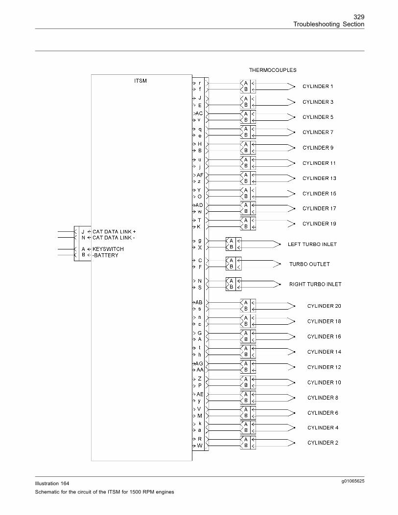
329Troubleshooting Section
g01065625Illustration 164Schematic for the circuit of the ITSM for 1500 RPM engines
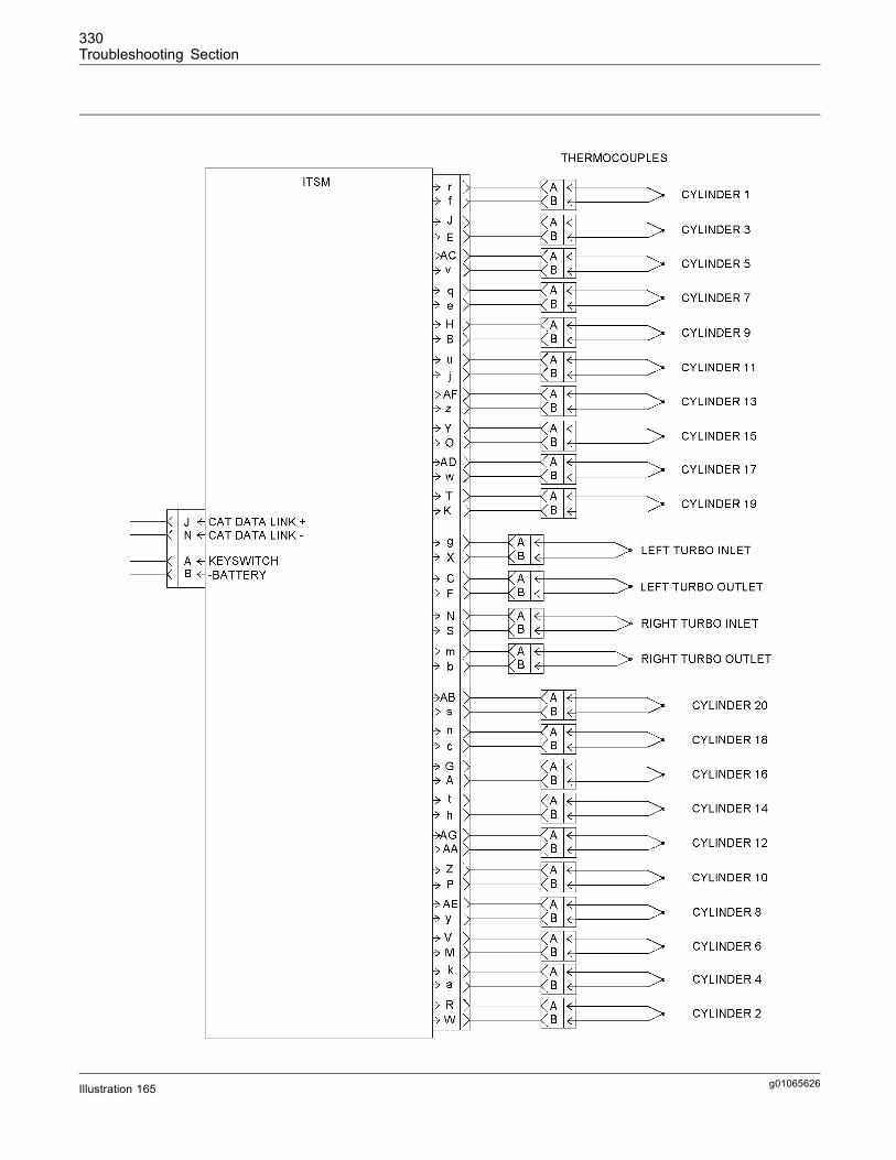
330Troubleshooting Section
g01065626Illustration 165
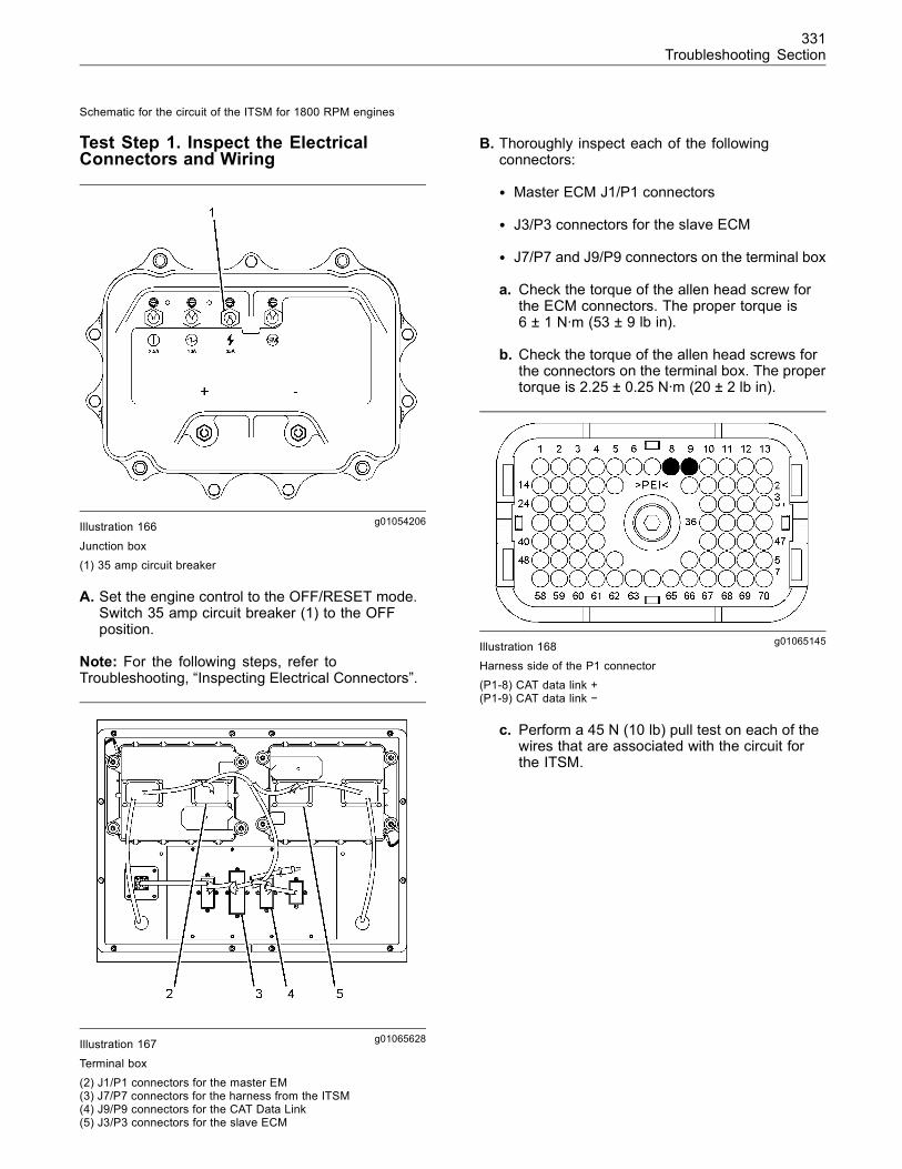
331Troubleshooting Section
Schematic for the circuit of the ITSM for 1800 RPM engines
Test Step 1. Inspect the ElectricalConnectors and Wiring
g01054206Illustration 166
Junction box(1) 35 amp circuit breaker
A. Set the engine control to the OFF/RESET mode.Switch 35 amp circuit breaker (1) to the OFFposition.
Note: For the following steps, refer toTroubleshooting, “Inspecting Electrical Connectors”.
g01065628Illustration 167
Terminal box(2) J1/P1 connectors for the master EM(3) J7/P7 connectors for the harness from the ITSM(4) J9/P9 connectors for the CAT Data Link(5) J3/P3 connectors for the slave ECM
B. Thoroughly inspect each of the followingconnectors:
• Master ECM J1/P1 connectors
• J3/P3 connectors for the slave ECM
• J7/P7 and J9/P9 connectors on the terminal box
a. Check the torque of the allen head screw forthe ECM connectors. The proper torque is6 ± 1 N·m (53 ± 9 lb in).
b. Check the torque of the allen head screws forthe connectors on the terminal box. The propertorque is 2.25 ± 0.25 N·m (20 ± 2 lb in).
g01065145Illustration 168Harness side of the P1 connector(P1-8) CAT data link +(P1-9) CAT data link −
c. Perform a 45 N (10 lb) pull test on each of thewires that are associated with the circuit forthe ITSM.
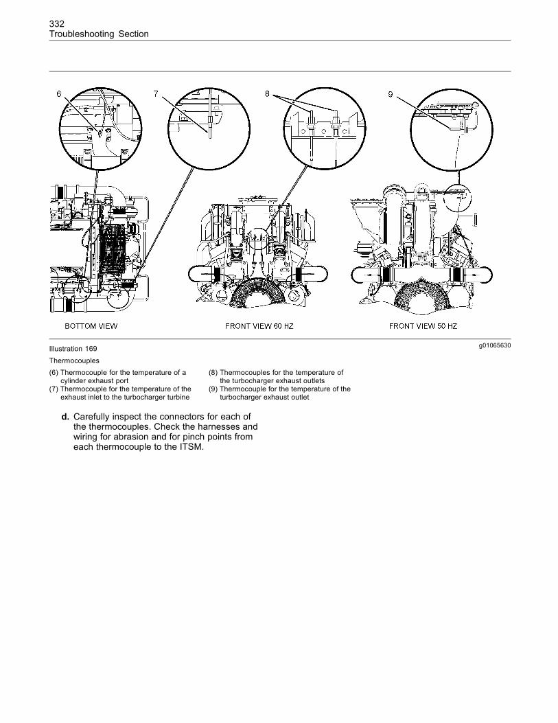
332Troubleshooting Section
g01065630Illustration 169
Thermocouples(6) Thermocouple for the temperature of a
cylinder exhaust port(7) Thermocouple for the temperature of the
exhaust inlet to the turbocharger turbine
(8) Thermocouples for the temperature ofthe turbocharger exhaust outlets
(9) Thermocouple for the temperature of theturbocharger exhaust outlet
d. Carefully inspect the connectors for each ofthe thermocouples. Check the harnesses andwiring for abrasion and for pinch points fromeach thermocouple to the ITSM.
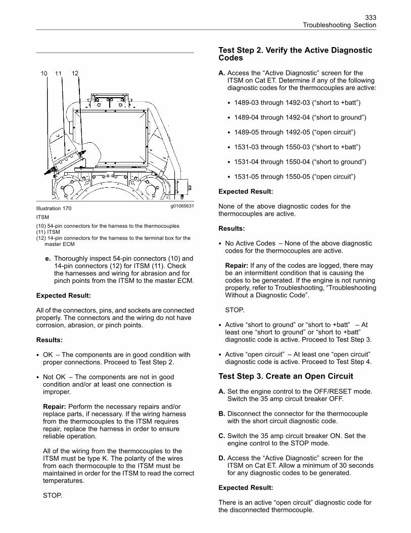
333Troubleshooting Section
g01065631Illustration 170
ITSM(10) 54-pin connectors for the harness to the thermocouples(11) ITSM(12) 14-pin connectors for the harness to the terminal box for the
master ECM
e. Thoroughly inspect 54-pin connectors (10) and14-pin connectors (12) for ITSM (11). Checkthe harnesses and wiring for abrasion and forpinch points from the ITSM to the master ECM.
Expected Result:
All of the connectors, pins, and sockets are connectedproperly. The connectors and the wiring do not havecorrosion, abrasion, or pinch points.
Results:
• OK – The components are in good condition withproper connections. Proceed to Test Step 2.
• Not OK – The components are not in goodcondition and/or at least one connection isimproper.
Repair: Perform the necessary repairs and/orreplace parts, if necessary. If the wiring harnessfrom the thermocouples to the ITSM requiresrepair, replace the harness in order to ensurereliable operation.
All of the wiring from the thermocouples to theITSM must be type K. The polarity of the wiresfrom each thermocouple to the ITSM must bemaintained in order for the ITSM to read the correcttemperatures.
STOP.
Test Step 2. Verify the Active DiagnosticCodes
A. Access the “Active Diagnostic” screen for theITSM on Cat ET. Determine if any of the followingdiagnostic codes for the thermocouples are active:
• 1489-03 through 1492-03 (“short to +batt”)
• 1489-04 through 1492-04 (“short to ground”)
• 1489-05 through 1492-05 (“open circuit”)
• 1531-03 through 1550-03 (“short to +batt”)
• 1531-04 through 1550-04 (“short to ground”)
• 1531-05 through 1550-05 (“open circuit”)
Expected Result:
None of the above diagnostic codes for thethermocouples are active.
Results:
• No Active Codes – None of the above diagnosticcodes for the thermocouples are active.
Repair: If any of the codes are logged, there maybe an intermittent condition that is causing thecodes to be generated. If the engine is not runningproperly, refer to Troubleshooting, “TroubleshootingWithout a Diagnostic Code”.
STOP.
• Active “short to ground” or “short to +batt” – Atleast one “short to ground” or “short to +batt”diagnostic code is active. Proceed to Test Step 3.
• Active “open circuit” – At least one “open circuit”diagnostic code is active. Proceed to Test Step 4.
Test Step 3. Create an Open Circuit
A. Set the engine control to the OFF/RESET mode.Switch the 35 amp circuit breaker OFF.
B. Disconnect the connector for the thermocouplewith the short circuit diagnostic code.
C. Switch the 35 amp circuit breaker ON. Set theengine control to the STOP mode.
D. Access the “Active Diagnostic” screen for theITSM on Cat ET. Allow a minimum of 30 secondsfor any diagnostic codes to be generated.
Expected Result:
There is an active “open circuit” diagnostic code forthe disconnected thermocouple.
334Troubleshooting Section
Results:
• Yes – There is an active “open circuit” diagnosticcode for the disconnected thermocouple. TheITSM and the harness are OK.
Repair: Perform the following procedure:
1. Thoroughly inspect the thermocouple’sconnectors. Ensure that the connectors and theseals are in good condition.
2. Reconnect the thermocouple’s connectors andcheck for an active short circuit diagnostic code.
If the short circuit diagnostic code becomesactive again, there is a problem with thethermocouple.
3. Disconnect the suspect thermocouple andconnect a thermocouple that is known to begood. Do not install the thermocouple into theengine yet.
4. Check for an active short circuit diagnostic code.
If the diagnostic code is not generated withthe good thermocouple, remove the suspectthermocouple from the engine. Install the goodthermocouple.
5. Clear the logged diagnostic codes.
STOP.
• No – There is not an active “open circuit” diagnosticcode for the disconnected thermocouple. Thereis a short circuit between the harness for thethermocouple and the ITSM. Proceed to Test Step5.
Test Step 4. Create a Short Circuit
A. Set the engine control to the OFF/RESET mode.Switch the 35 amp circuit breaker OFF.
B. Disconnect the connector for the thermocouplewith the open circuit diagnostic code.
C. Install a jumper wire into terminals A and B on theharness connector for the suspect thermocouple.
D. Switch the 35 amp circuit breaker ON. Set theengine control to the STOP mode.
E. Access the “Active Diagnostic” screen for theITSM on Cat ET. Allow a minimum of 30 secondsfor any diagnostic codes to be generated. Observethe “Active Diagnostic” screen.
F. Remove the jumper wire and observe the “ActiveDiagnostic” screen. Allow a minimum of 30seconds for any diagnostic codes to be generated.
Expected Result:
When the jumper wire was installed, a “short circuit”diagnostic code was generated. When the jumperwire was removed, the “open circuit” diagnostic coderecurred.
Results:
• Yes – When the jumper wire was installed, a“short circuit” diagnostic code was generated.When the jumper wire was removed, the “opencircuit” diagnostic code recurred. The ITSM andthe harness are OK.
Repair: Perform the following procedure:
1. Thoroughly inspect the thermocouple’sconnectors. Ensure that the connectors and theseals are in good condition.
2. Reconnect the thermocouple’s connectors andcheck for an active open circuit diagnostic code.
If the open circuit diagnostic code becomesactive again, there is a problem with thethermocouple.
3. Disconnect the suspect thermocouple andconnect a thermocouple that is known to begood. Do not install the good thermocouple intothe engine yet.
4. Check for an active open circuit diagnostic code.
If the diagnostic code is not generated withthe good thermocouple, remove the suspectthermocouple from the engine. Install the goodthermocouple.
5. Clear the logged diagnostic codes.
STOP.
• No – When the jumper wire was installed, the“open circuit” diagnostic code recurred. There isprobably an open circuit in the harness betweenthe ITSM and the connector for the thermocouple.
Repair: Remove the jumper wire.
Proceed to Test Step 5.
Test Step 5. Check the ITSM
A. Set the engine control to the OFF/RESET mode.Switch the 35 amp circuit breaker OFF.
335Troubleshooting Section
B. Disconnect the 54-pin connector from the ITSM.Thoroughly inspect the 54-pin connectors. Ensurethat the connectors are in good condition.
C. Switch the 35 amp circuit breaker ON. Set theengine control to the STOP mode.
Note:When the 54-pin connectors are disconnected,an active “open circuit” diagnostic code will begenerated for all of the thermocouples. This isnormal. Only pay attention to the diagnostic codes forthe suspect thermocouple.
D. Access the “Active Diagnostic” screen for theITSM on Cat ET. Allow a minimum of 30 secondsfor any diagnostic codes to be generated. Observethe “Active Diagnostic” screen.
E. Set the engine control to the OFF/RESET mode.Switch the 35 amp circuit breaker OFF.
F. Install a jumper wire into the terminals for thesuspect sensor on the 54-pin connector on theITSM. For identification of the terminals, refer toIllustration 164 or 165.
G. Switch the 35 amp circuit breaker ON. Set theengine control to the STOP mode. Observe the“Active Diagnostic” screen. Allow a minimum of 30seconds for any diagnostic codes to be generated.
Expected Result:
When the 54-pin connectors were disconnected, an“open circuit” diagnostic code was generated for thesuspect sensor. When the jumper wire was installed,a “short circuit” diagnostic code was generated.
Results:
• Yes – When the 54-pin connectors weredisconnected, an “open circuit” diagnostic codewas generated for the suspect sensor. Whenthe jumper wire was installed, a “short circuit”diagnostic code was generated. The ITSM isOK. There is a problem in the harness betweenthe ITSM and the connector for the suspectthermocouple.
Repair: Remove the jumper wire. Replace theharness in order to ensure reliable operation. Clearthe logged diagnostic codes and verify that theproblem is resolved.
All of the wiring from the thermocouples to theITSM must be K type. The polarity of the wiresfrom each thermocouple to the ITSM must bemaintained in order for the ITSM to read the correcttemperatures.
STOP.
• No – Either of the following results or both of theresults occurred: When the 54-pin connectors weredisconnected, an “open circuit” diagnostic codewas not generated for the suspect sensor. Whenthe jumper wire was installed, a “short circuit”diagnostic code was not generated. There may bea problem with the ITSM.
Repair: It is unlikely that the ITSM has failed. Exitthis procedure and perform this procedure again. Ifthe problem is not resolved, perform the followingsteps:
1. Set the engine control to the OFF/RESETmode. Switch the 35 amp circuit breaker OFF.
2. Remove the jumper wire from the connector onthe ITSM.
3. Temporarily install a new ITSM. Refer toTroubleshooting, “Replacing the ITSM”.
4. If the problem is resolved with the new ITSM,install the original ITSM and verify that theproblem returns. If the new ITSM operatescorrectly and the original ITSM does not operatecorrectly, replace the original ITSM. Refer toTroubleshooting, “Replacing the ITSM”.
STOP.
i02089570
PWM SensorSMCS Code: 5574-038
System Operation Description:
The engine contains the following Pulse WidthModulated sensors (PWM):
• Engine coolant pressure (outlet)
• Inlet manifold air pressure
A PWM sensor produces a digital signal. In a digitalsignal, the duty cycle varies as the input conditionchanges. The frequency remains constant. Refer toIllustration 171.
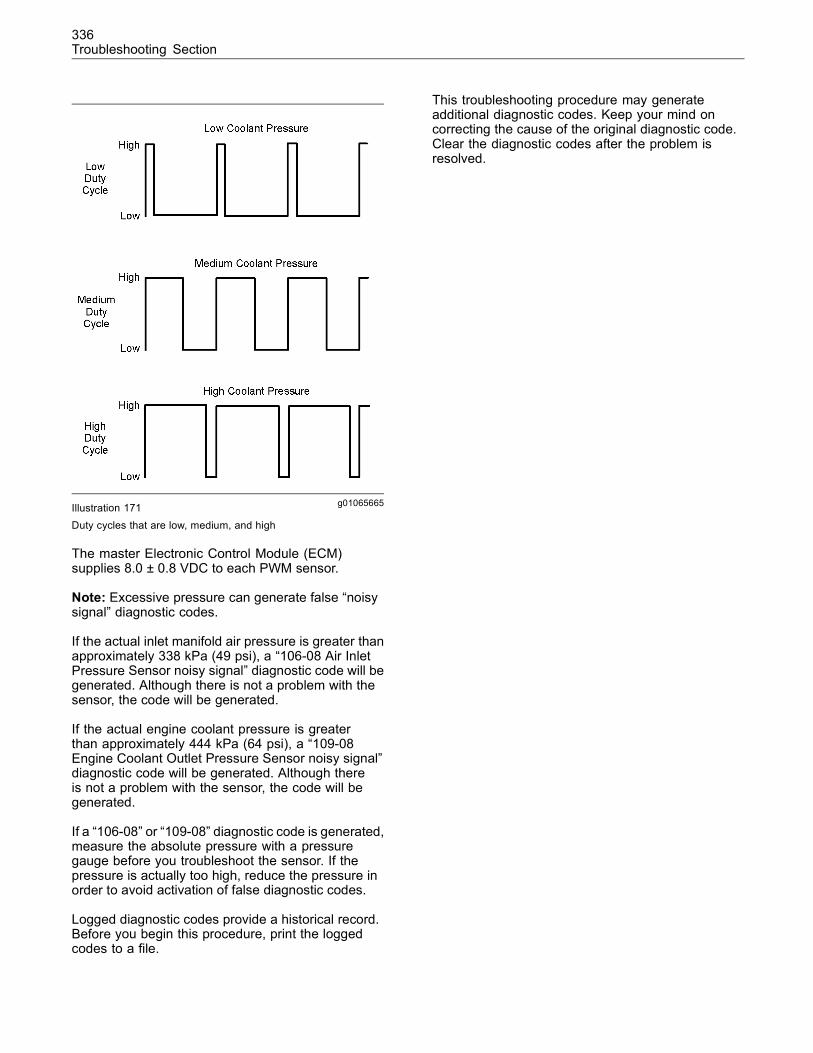
336Troubleshooting Section
g01065665Illustration 171
Duty cycles that are low, medium, and high
The master Electronic Control Module (ECM)supplies 8.0 ± 0.8 VDC to each PWM sensor.
Note: Excessive pressure can generate false “noisysignal” diagnostic codes.
If the actual inlet manifold air pressure is greater thanapproximately 338 kPa (49 psi), a “106-08 Air InletPressure Sensor noisy signal” diagnostic code will begenerated. Although there is not a problem with thesensor, the code will be generated.
If the actual engine coolant pressure is greaterthan approximately 444 kPa (64 psi), a “109-08Engine Coolant Outlet Pressure Sensor noisy signal”diagnostic code will be generated. Although thereis not a problem with the sensor, the code will begenerated.
If a “106-08” or “109-08” diagnostic code is generated,measure the absolute pressure with a pressuregauge before you troubleshoot the sensor. If thepressure is actually too high, reduce the pressure inorder to avoid activation of false diagnostic codes.
Logged diagnostic codes provide a historical record.Before you begin this procedure, print the loggedcodes to a file.
This troubleshooting procedure may generateadditional diagnostic codes. Keep your mind oncorrecting the cause of the original diagnostic code.Clear the diagnostic codes after the problem isresolved.
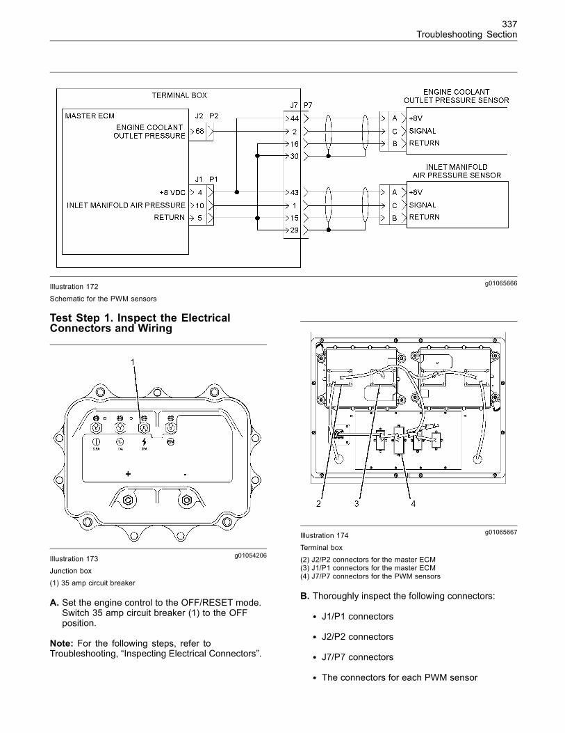
337Troubleshooting Section
g01065666Illustration 172
Schematic for the PWM sensors
Test Step 1. Inspect the ElectricalConnectors and Wiring
g01054206Illustration 173
Junction box
(1) 35 amp circuit breaker
A. Set the engine control to the OFF/RESET mode.Switch 35 amp circuit breaker (1) to the OFFposition.
Note: For the following steps, refer toTroubleshooting, “Inspecting Electrical Connectors”.
g01065667Illustration 174
Terminal box(2) J2/P2 connectors for the master ECM(3) J1/P1 connectors for the master ECM(4) J7/P7 connectors for the PWM sensors
B. Thoroughly inspect the following connectors:
• J1/P1 connectors
• J2/P2 connectors
• J7/P7 connectors
• The connectors for each PWM sensor
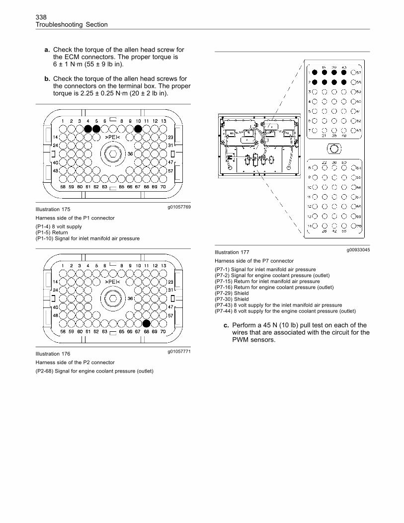
338Troubleshooting Section
a. Check the torque of the allen head screw forthe ECM connectors. The proper torque is6 ± 1 N·m (55 ± 9 lb in).
b. Check the torque of the allen head screws forthe connectors on the terminal box. The propertorque is 2.25 ± 0.25 N·m (20 ± 2 lb in).
g01057769Illustration 175
Harness side of the P1 connector(P1-4) 8 volt supply(P1-5) Return(P1-10) Signal for inlet manifold air pressure
g01057771Illustration 176Harness side of the P2 connector
(P2-68) Signal for engine coolant pressure (outlet)
g00933045Illustration 177
Harness side of the P7 connector(P7-1) Signal for inlet manifold air pressure(P7-2) Signal for engine coolant pressure (outlet)(P7-15) Return for inlet manifold air pressure(P7-16) Return for engine coolant pressure (outlet)(P7-29) Shield(P7-30) Shield(P7-43) 8 volt supply for the inlet manifold air pressure(P7-44) 8 volt supply for the engine coolant pressure (outlet)
c. Perform a 45 N (10 lb) pull test on each of thewires that are associated with the circuit for thePWM sensors.
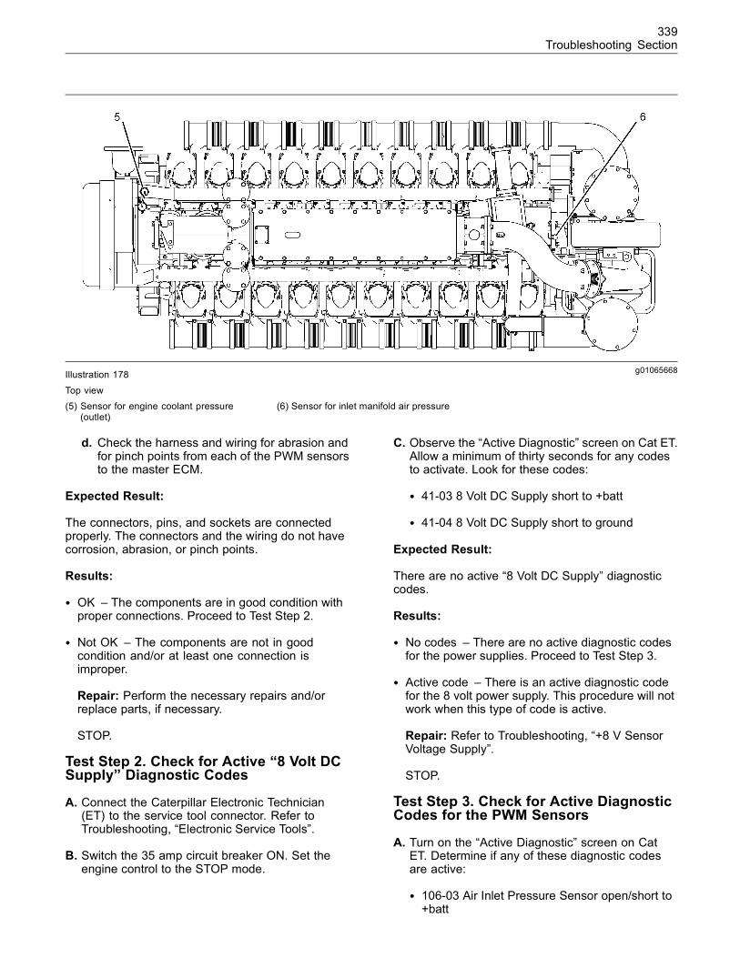
339Troubleshooting Section
g01065668Illustration 178
Top view(5) Sensor for engine coolant pressure
(outlet)(6) Sensor for inlet manifold air pressure
d. Check the harness and wiring for abrasion andfor pinch points from each of the PWM sensorsto the master ECM.
Expected Result:
The connectors, pins, and sockets are connectedproperly. The connectors and the wiring do not havecorrosion, abrasion, or pinch points.
Results:
• OK – The components are in good condition withproper connections. Proceed to Test Step 2.
• Not OK – The components are not in goodcondition and/or at least one connection isimproper.
Repair: Perform the necessary repairs and/orreplace parts, if necessary.
STOP.
Test Step 2. Check for Active “8 Volt DCSupply” Diagnostic Codes
A. Connect the Caterpillar Electronic Technician(ET) to the service tool connector. Refer toTroubleshooting, “Electronic Service Tools”.
B. Switch the 35 amp circuit breaker ON. Set theengine control to the STOP mode.
C. Observe the “Active Diagnostic” screen on Cat ET.Allow a minimum of thirty seconds for any codesto activate. Look for these codes:
• 41-03 8 Volt DC Supply short to +batt
• 41-04 8 Volt DC Supply short to ground
Expected Result:
There are no active “8 Volt DC Supply” diagnosticcodes.
Results:
• No codes – There are no active diagnostic codesfor the power supplies. Proceed to Test Step 3.
• Active code – There is an active diagnostic codefor the 8 volt power supply. This procedure will notwork when this type of code is active.
Repair: Refer to Troubleshooting, “+8 V SensorVoltage Supply”.
STOP.
Test Step 3. Check for Active DiagnosticCodes for the PWM Sensors
A. Turn on the “Active Diagnostic” screen on CatET. Determine if any of these diagnostic codesare active:
• 106-03 Air Inlet Pressure Sensor open/short to+batt
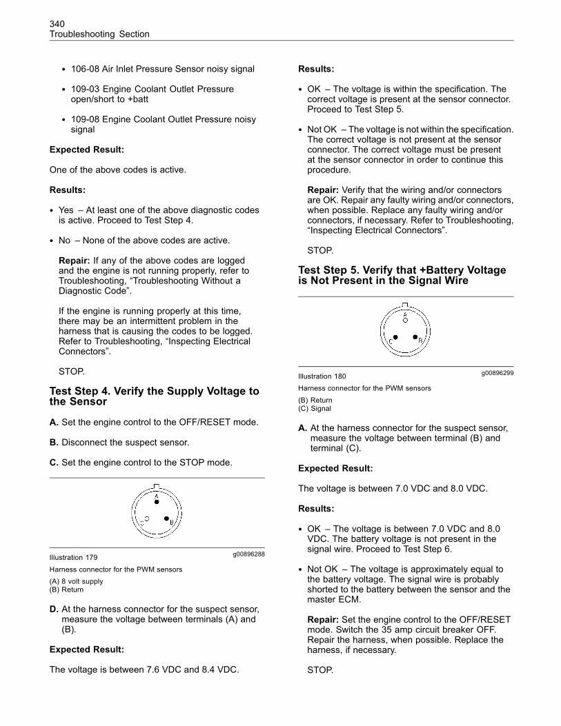
340Troubleshooting Section
• 106-08 Air Inlet Pressure Sensor noisy signal
• 109-03 Engine Coolant Outlet Pressureopen/short to +batt
• 109-08 Engine Coolant Outlet Pressure noisysignal
Expected Result:
One of the above codes is active.
Results:
• Yes – At least one of the above diagnostic codesis active. Proceed to Test Step 4.
• No – None of the above codes are active.
Repair: If any of the above codes are loggedand the engine is not running properly, refer toTroubleshooting, “Troubleshooting Without aDiagnostic Code”.
If the engine is running properly at this time,there may be an intermittent problem in theharness that is causing the codes to be logged.Refer to Troubleshooting, “Inspecting ElectricalConnectors”.
STOP.
Test Step 4. Verify the Supply Voltage tothe Sensor
A. Set the engine control to the OFF/RESET mode.
B. Disconnect the suspect sensor.
C. Set the engine control to the STOP mode.
g00896288Illustration 179
Harness connector for the PWM sensors(A) 8 volt supply(B) Return
D. At the harness connector for the suspect sensor,measure the voltage between terminals (A) and(B).
Expected Result:
The voltage is between 7.6 VDC and 8.4 VDC.
Results:
• OK – The voltage is within the specification. Thecorrect voltage is present at the sensor connector.Proceed to Test Step 5.
• Not OK – The voltage is not within the specification.The correct voltage is not present at the sensorconnector. The correct voltage must be presentat the sensor connector in order to continue thisprocedure.
Repair: Verify that the wiring and/or connectorsare OK. Repair any faulty wiring and/or connectors,when possible. Replace any faulty wiring and/orconnectors, if necessary. Refer to Troubleshooting,“Inspecting Electrical Connectors”.
STOP.
Test Step 5. Verify that +Battery Voltageis Not Present in the Signal Wire
g00896299Illustration 180Harness connector for the PWM sensors
(B) Return(C) Signal
A. At the harness connector for the suspect sensor,measure the voltage between terminal (B) andterminal (C).
Expected Result:
The voltage is between 7.0 VDC and 8.0 VDC.
Results:
• OK – The voltage is between 7.0 VDC and 8.0VDC. The battery voltage is not present in thesignal wire. Proceed to Test Step 6.
• Not OK – The voltage is approximately equal tothe battery voltage. The signal wire is probablyshorted to the battery between the sensor and themaster ECM.
Repair: Set the engine control to the OFF/RESETmode. Switch the 35 amp circuit breaker OFF.Repair the harness, when possible. Replace theharness, if necessary.
STOP.
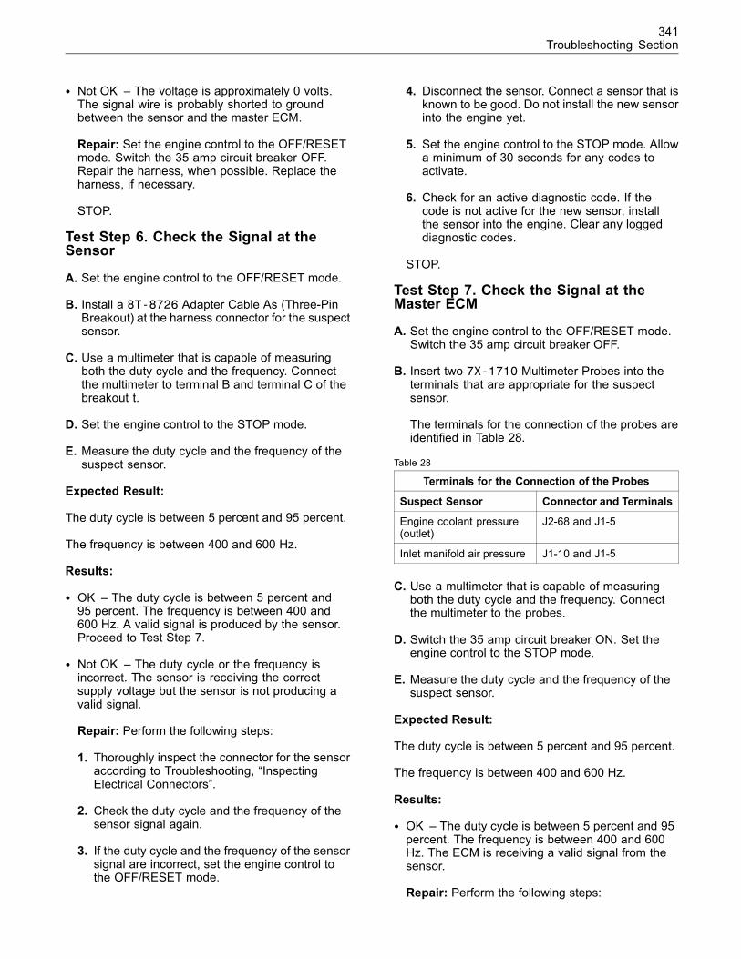
341Troubleshooting Section
• Not OK – The voltage is approximately 0 volts.The signal wire is probably shorted to groundbetween the sensor and the master ECM.
Repair: Set the engine control to the OFF/RESETmode. Switch the 35 amp circuit breaker OFF.Repair the harness, when possible. Replace theharness, if necessary.
STOP.
Test Step 6. Check the Signal at theSensor
A. Set the engine control to the OFF/RESET mode.
B. Install a 8T-8726 Adapter Cable As (Three-PinBreakout) at the harness connector for the suspectsensor.
C. Use a multimeter that is capable of measuringboth the duty cycle and the frequency. Connectthe multimeter to terminal B and terminal C of thebreakout t.
D. Set the engine control to the STOP mode.
E. Measure the duty cycle and the frequency of thesuspect sensor.
Expected Result:
The duty cycle is between 5 percent and 95 percent.
The frequency is between 400 and 600 Hz.
Results:
• OK – The duty cycle is between 5 percent and95 percent. The frequency is between 400 and600 Hz. A valid signal is produced by the sensor.Proceed to Test Step 7.
• Not OK – The duty cycle or the frequency isincorrect. The sensor is receiving the correctsupply voltage but the sensor is not producing avalid signal.
Repair: Perform the following steps:
1. Thoroughly inspect the connector for the sensoraccording to Troubleshooting, “InspectingElectrical Connectors”.
2. Check the duty cycle and the frequency of thesensor signal again.
3. If the duty cycle and the frequency of the sensorsignal are incorrect, set the engine control tothe OFF/RESET mode.
4. Disconnect the sensor. Connect a sensor that isknown to be good. Do not install the new sensorinto the engine yet.
5. Set the engine control to the STOP mode. Allowa minimum of 30 seconds for any codes toactivate.
6. Check for an active diagnostic code. If thecode is not active for the new sensor, installthe sensor into the engine. Clear any loggeddiagnostic codes.
STOP.
Test Step 7. Check the Signal at theMaster ECM
A. Set the engine control to the OFF/RESET mode.Switch the 35 amp circuit breaker OFF.
B. Insert two 7X-1710 Multimeter Probes into theterminals that are appropriate for the suspectsensor.
The terminals for the connection of the probes areidentified in Table 28.
Table 28
Terminals for the Connection of the Probes
Suspect Sensor Connector and Terminals
Engine coolant pressure(outlet)
J2-68 and J1-5
Inlet manifold air pressure J1-10 and J1-5
C. Use a multimeter that is capable of measuringboth the duty cycle and the frequency. Connectthe multimeter to the probes.
D. Switch the 35 amp circuit breaker ON. Set theengine control to the STOP mode.
E. Measure the duty cycle and the frequency of thesuspect sensor.
Expected Result:
The duty cycle is between 5 percent and 95 percent.
The frequency is between 400 and 600 Hz.
Results:
• OK – The duty cycle is between 5 percent and 95percent. The frequency is between 400 and 600Hz. The ECM is receiving a valid signal from thesensor.
Repair: Perform the following steps:
342Troubleshooting Section
1. Set the engine control to the OFF/RESETmode. Switch the 35 amp circuit breaker OFF.
2. Switch the 35 amp circuit breaker ON. Set theengine control to the STOP mode.
3. Check “Status Screen Group 2” on Cat ET. Lookfor a valid signal.
It is possible that the actual air inlet pressure isless than the pressure that can be measured bythe sensor during low idle operation (26.7 kPa(3.87 psi)). This causes the master ECM to setthe 106-03 diagnostic code although there is noshort circuit to the +Battery side. In this case,adjust the derivative gain and the fuel quality inorder to make the engine more stable at low idle.Refer to Troubleshooting, “System ConfigurationParameters”.
Otherwise, verify that the master ECM is receivingthe correct voltage. Refer to Troubleshooting,“Electrical Power Supply”.
If the condition is not resolved, temporarily installa new master ECM. Refer to Troubleshooting,“Replacing the ECM”.
If the problem is resolved with the new ECM,install the original ECM and verify that the problemreturns. If the new ECM operates correctly and theoriginal ECM does not operate correctly, replacethe original ECM. Refer to Troubleshooting,“Replacing the ECM”.
STOP.
• Not OK – The duty cycle or the frequency isincorrect. The sensor is producing a valid signalbut the signal does not reach the master ECM.There is a problem in the harness between thesensor and the master ECM.
Repair: Repair the harness, when possible.Replace the harness, if necessary.
STOP.
i02089593
Throttle ActuatorSMCS Code: 1716-038
System Operation Description:
The throttle actuator is an electronic actuator thatworks with the master Electronic Control Module(ECM) in order to ensure the correct throttle positionin all conditions of engine operation.
The master ECM and the throttle actuatorcommunicate via the CAN data link. The masterECM sends a command signal to the actuator. Theactuator sends the following information to the masterECM: actuator position, CCM heartbeat, softwareversion, and internal fault diagnosis.
If the master ECM cannot communicate with thethrottle actuator, the master ECM activates a 1440-09diagnostic code and the engine is shut down. A1440-09 diagnostic code is probably caused by aproblem with an electrical connector or a harness.The next likely cause is a problem with the actuator.The least likely cause is a problem with the masterECM.
Terminating resistors must be connected to eachend of the CAN data link. The terminating resistorsimprove the communication between the devices. Ifthere is an intermittent diagnostic code for any of thedevices that are connected to the CAN data link, besure to check the terminating resistor that is insidethe terminal box. Also check the jumper wire that isconnected between terminals J and K on the actuatorfor the bypass valve. Make repairs, when possible.Replace parts, if necessary.
Logged diagnostic codes provide a historical record.Before you begin this procedure, use the CaterpillarElectronic Technician (ET) to print the logged codesto a file.
This troubleshooting procedure may generateadditional diagnostic codes. Keep your mind oncorrecting the cause of the original diagnostic code.Clear the diagnostic codes after the problem isresolved.
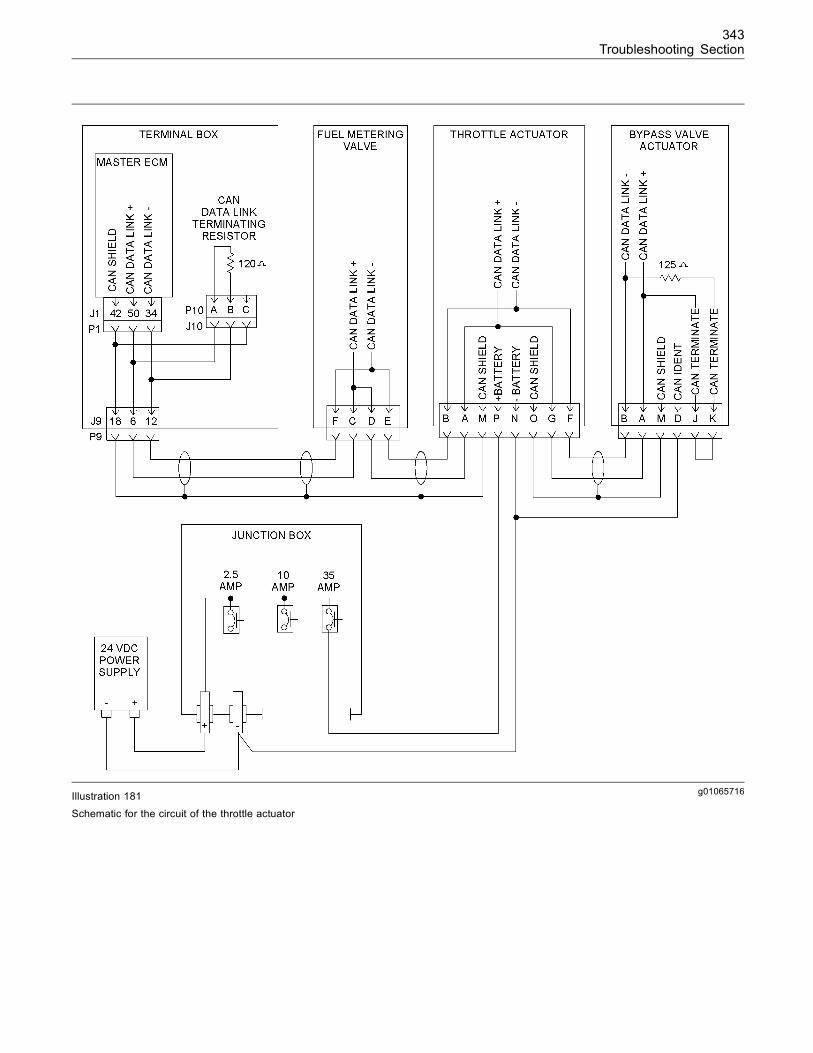
343Troubleshooting Section
g01065716Illustration 181
Schematic for the circuit of the throttle actuator
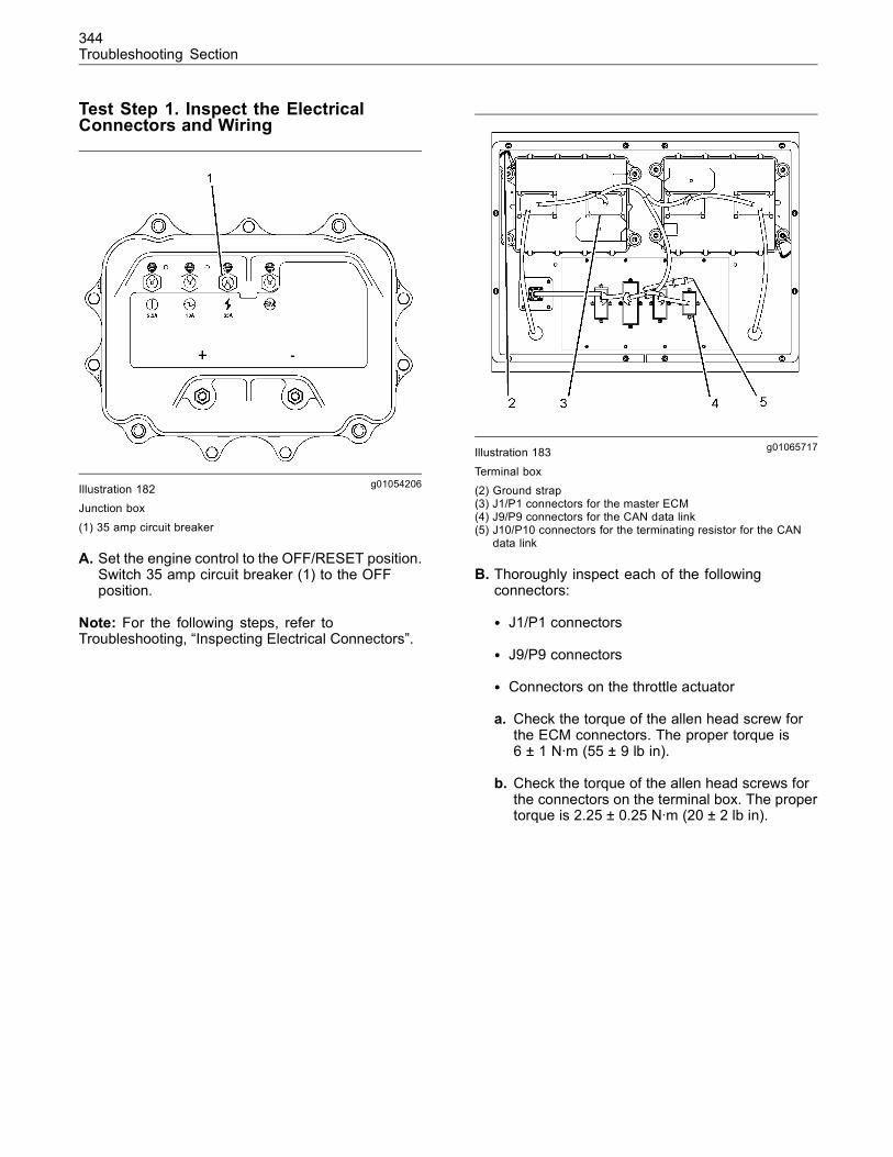
344Troubleshooting Section
Test Step 1. Inspect the ElectricalConnectors and Wiring
g01054206Illustration 182Junction box
(1) 35 amp circuit breaker
A. Set the engine control to the OFF/RESET position.Switch 35 amp circuit breaker (1) to the OFFposition.
Note: For the following steps, refer toTroubleshooting, “Inspecting Electrical Connectors”.
g01065717Illustration 183
Terminal box(2) Ground strap(3) J1/P1 connectors for the master ECM(4) J9/P9 connectors for the CAN data link(5) J10/P10 connectors for the terminating resistor for the CAN
data link
B. Thoroughly inspect each of the followingconnectors:
• J1/P1 connectors
• J9/P9 connectors
• Connectors on the throttle actuator
a. Check the torque of the allen head screw forthe ECM connectors. The proper torque is6 ± 1 N·m (55 ± 9 lb in).
b. Check the torque of the allen head screws forthe connectors on the terminal box. The propertorque is 2.25 ± 0.25 N·m (20 ± 2 lb in).
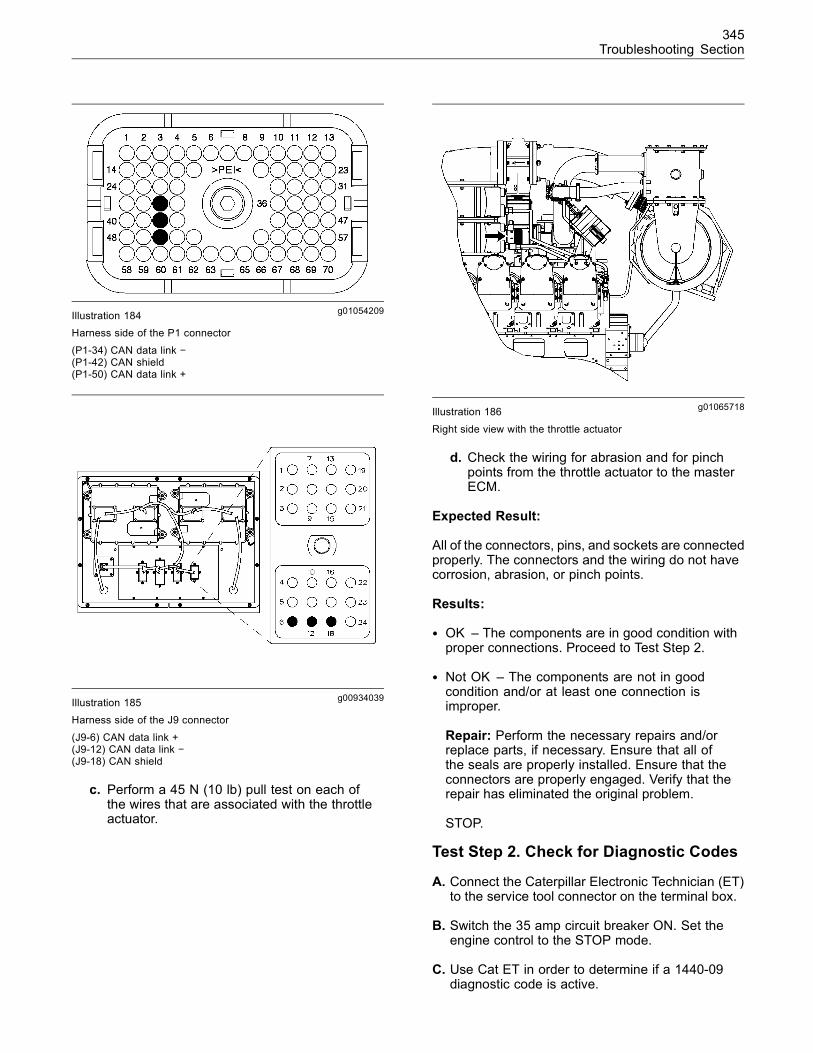
345Troubleshooting Section
g01054209Illustration 184Harness side of the P1 connector
(P1-34) CAN data link −(P1-42) CAN shield(P1-50) CAN data link +
g00934039Illustration 185Harness side of the J9 connector
(J9-6) CAN data link +(J9-12) CAN data link −(J9-18) CAN shield
c. Perform a 45 N (10 lb) pull test on each ofthe wires that are associated with the throttleactuator.
g01065718Illustration 186
Right side view with the throttle actuator
d. Check the wiring for abrasion and for pinchpoints from the throttle actuator to the masterECM.
Expected Result:
All of the connectors, pins, and sockets are connectedproperly. The connectors and the wiring do not havecorrosion, abrasion, or pinch points.
Results:
• OK – The components are in good condition withproper connections. Proceed to Test Step 2.
• Not OK – The components are not in goodcondition and/or at least one connection isimproper.
Repair: Perform the necessary repairs and/orreplace parts, if necessary. Ensure that all ofthe seals are properly installed. Ensure that theconnectors are properly engaged. Verify that therepair has eliminated the original problem.
STOP.
Test Step 2. Check for Diagnostic Codes
A. Connect the Caterpillar Electronic Technician (ET)to the service tool connector on the terminal box.
B. Switch the 35 amp circuit breaker ON. Set theengine control to the STOP mode.
C. Use Cat ET in order to determine if a 1440-09diagnostic code is active.
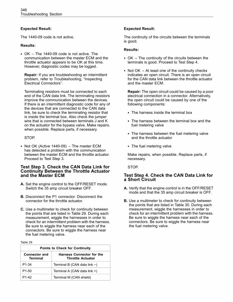
346Troubleshooting Section
Expected Result:
The 1440-09 code is not active.
Results:
• OK – The 1440-09 code is not active. Thecommunication between the master ECM and thethrottle actuator appears to be OK at this time.However, diagnostic codes may be logged.
Repair: If you are troubleshooting an intermittentproblem, refer to Troubleshooting, “InspectingElectrical Connectors”.
Terminating resistors must be connected to eachend of the CAN data link. The terminating resistorsimprove the communication between the devices.If there is an intermittent diagnostic code for any ofthe devices that are connected to the CAN datalink, be sure to check the terminating resistor thatis inside the terminal box. Also check the jumperwire that is connected between terminals J and Kon the actuator for the bypass valve. Make repairs,when possible. Replace parts, if necessary.
STOP.
• Not OK (Active 1440-09) – The master ECMhas detected a problem with the communicationbetween the master ECM and the throttle actuator.Proceed to Test Step 3.
Test Step 3. Check the CAN Data Link forContinuity Between the Throttle Actuatorand the Master ECM
A. Set the engine control to the OFF/RESET mode.Switch the 35 amp circuit breaker OFF.
B. Disconnect the P1 connector. Disconnect theconnector for the throttle actuator.
C. Use a multimeter to check for continuity betweenthe points that are listed in Table 29. During eachmeasurement, wiggle the harnesses in order tocheck for an intermittent problem with the harness.Be sure to wiggle the harness near each of theconnectors. Be sure to wiggle the harness nearthe fuel metering valve.
Table 29
Points to Check for Continuity
Connector andTerminal
Harness Connector for theThrottle Actuator
P1-34 Terminal B (CAN data link −)
P1-50 Terminal A (CAN data link +)
P1-42 Terminal M (CAN shield)
Expected Result:
The continuity of the circuits between the terminalsis good.
Results:
• OK – The continuity of the circuits between theterminals is good. Proceed to Test Step 4.
• Not OK – At least one of the continuity checksindicates an open circuit. There is an open circuitfor the CAN data link between the throttle actuatorand the master ECM.
Repair: The open circuit could be caused by a poorelectrical connection in a connector. Alternatively,the open circuit could be caused by one of thefollowing components:
• The harness inside the terminal box
• The harness between the terminal box and thefuel metering valve
• The harness between the fuel metering valveand the throttle actuator
• The fuel metering valve
Make repairs, when possible. Replace parts, ifnecessary.
STOP.
Test Step 4. Check the CAN Data Link fora Short Circuit
A. Verify that the engine control is in the OFF/RESETmode and that the 35 amp circuit breaker is OFF.
B. Use a multimeter to check for continuity betweenthe points that are listed in Table 30. During eachmeasurement, wiggle the harnesses in order tocheck for an intermittent problem with the harness.Be sure to wiggle the harness near each of theconnectors. Be sure to wiggle the harness nearthe fuel metering valve.
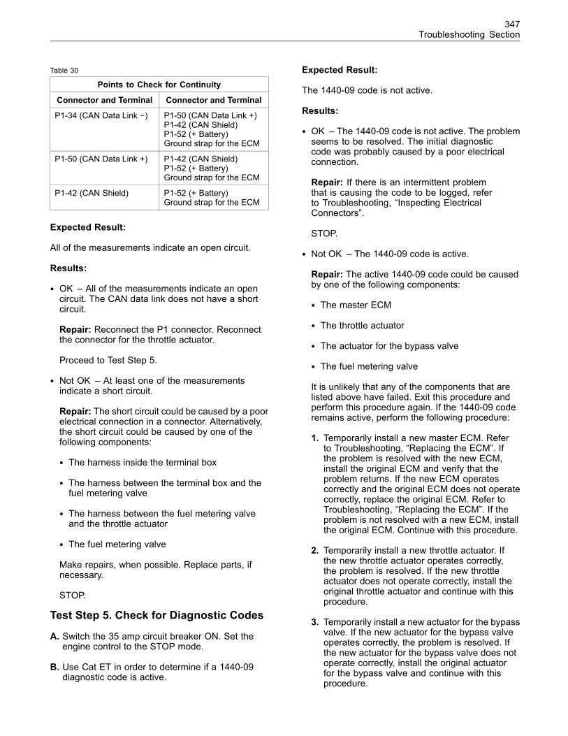
347Troubleshooting Section
Table 30
Points to Check for Continuity
Connector and Terminal Connector and Terminal
P1-34 (CAN Data Link −) P1-50 (CAN Data Link +)P1-42 (CAN Shield)P1-52 (+ Battery)Ground strap for the ECM
P1-50 (CAN Data Link +) P1-42 (CAN Shield)P1-52 (+ Battery)Ground strap for the ECM
P1-42 (CAN Shield) P1-52 (+ Battery)Ground strap for the ECM
Expected Result:
All of the measurements indicate an open circuit.
Results:
• OK – All of the measurements indicate an opencircuit. The CAN data link does not have a shortcircuit.
Repair: Reconnect the P1 connector. Reconnectthe connector for the throttle actuator.
Proceed to Test Step 5.
• Not OK – At least one of the measurementsindicate a short circuit.
Repair: The short circuit could be caused by a poorelectrical connection in a connector. Alternatively,the short circuit could be caused by one of thefollowing components:
• The harness inside the terminal box
• The harness between the terminal box and thefuel metering valve
• The harness between the fuel metering valveand the throttle actuator
• The fuel metering valve
Make repairs, when possible. Replace parts, ifnecessary.
STOP.
Test Step 5. Check for Diagnostic Codes
A. Switch the 35 amp circuit breaker ON. Set theengine control to the STOP mode.
B. Use Cat ET in order to determine if a 1440-09diagnostic code is active.
Expected Result:
The 1440-09 code is not active.
Results:
• OK – The 1440-09 code is not active. The problemseems to be resolved. The initial diagnosticcode was probably caused by a poor electricalconnection.
Repair: If there is an intermittent problemthat is causing the code to be logged, referto Troubleshooting, “Inspecting ElectricalConnectors”.
STOP.
• Not OK – The 1440-09 code is active.
Repair: The active 1440-09 code could be causedby one of the following components:
• The master ECM
• The throttle actuator
• The actuator for the bypass valve
• The fuel metering valve
It is unlikely that any of the components that arelisted above have failed. Exit this procedure andperform this procedure again. If the 1440-09 coderemains active, perform the following procedure:
1. Temporarily install a new master ECM. Referto Troubleshooting, “Replacing the ECM”. Ifthe problem is resolved with the new ECM,install the original ECM and verify that theproblem returns. If the new ECM operatescorrectly and the original ECM does not operatecorrectly, replace the original ECM. Refer toTroubleshooting, “Replacing the ECM”. If theproblem is not resolved with a new ECM, installthe original ECM. Continue with this procedure.
2. Temporarily install a new throttle actuator. Ifthe new throttle actuator operates correctly,the problem is resolved. If the new throttleactuator does not operate correctly, install theoriginal throttle actuator and continue with thisprocedure.
3. Temporarily install a new actuator for the bypassvalve. If the new actuator for the bypass valveoperates correctly, the problem is resolved. Ifthe new actuator for the bypass valve does notoperate correctly, install the original actuatorfor the bypass valve and continue with thisprocedure.

348Troubleshooting Section
4. Temporarily install a new fuel metering valve.If the new fuel metering valve operatescorrectly, the problem is resolved. If the newfuel metering valve does not operate correctly,install the original fuel metering valve. Referto Troubleshooting, “Inspecting ElectricalConnectors”.
STOP.
349Troubleshooting Section
Calibration Proceduresi02089646
Engine Speed/Timing Sensor -CalibrateSMCS Code: 1912-524
System Operation Description:
The master Electronic Control Module (ECM) hasthe ability to calibrate the mechanical differencesbetween the Top Center (TC) of the flywheel andthe TC of the timing gear on the left rear camshaftgear. A magnetic transducer signals the TC of theflywheel to the master ECM when the TC hole on theflywheel passes beneath the transducer. The enginespeed/timing sensor signals the TC of the timing gearto the master ECM. Any offset between the TC ofthe flywheel and the TC of the timing gear is storedinto memory. The master ECM communicates theinformation from the calibration to the slave ECM viathe CAT data link.
Calibration of the timing is required only after thefollowing circumstances:
• The master ECM has been replaced.
• The timing gear and/or the rear gear train havebeen adjusted.
• The timing gear and/or the rear gear train havebeen replaced.
Note: The “261-13 Engine Timing calibrationrequired” diagnostic code is generated only for amaster ECM that has never performed a timingcalibration.
The calibration procedure is initiated with theCaterpillar Electronic Technician (ET).
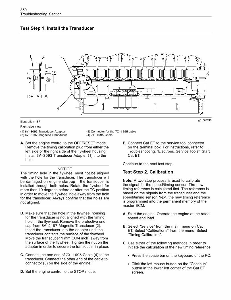
350Troubleshooting Section
Test Step 1. Install the Transducer
g01065745Illustration 187Right side view
(1) 6V-3093 Transducer Adapter(2) 6V-2197 Magnetic Transducer
(3) Connector for the 7X-1695 cable(4) 7X-1695 Cable
A. Set the engine control to the OFF/RESET mode.Remove the timing calibration plug from either theleft side or the right side of the flywheel housing.Install 6V-3093 Transducer Adapter (1) into thehole.
NOTICEThe timing hole in the flywheel must not be alignedwith the hole for the transducer. The transducer willbe damaged on engine start-up if the transducer isinstalled through both holes. Rotate the flywheel formore than 10 degrees before or after the TC positionin order to move the flywheel hole away from the holefor the transducer. Always confirm that the holes arenot aligned.
B. Make sure that the hole in the flywheel housingfor the transducer is not aligned with the timinghole in the flywheel. Remove the protective endcap from 6V-2197 Magnetic Transducer (2).Insert the transducer into the adapter until thetransducer contacts the surface of the flywheel.Move the transducer 1 mm (0.04 inch) away fromthe surface of the flywheel. Tighten the nut on theadapter in order to secure the transducer in place.
C. Connect the one end of 7X-1695 Cable (4) to thetransducer. Connect the other end of the cable toconnector (3) on the side of the engine.
D. Set the engine control to the STOP mode.
E. Connect Cat ET to the service tool connectoron the terminal box. For instructions, refer toTroubleshooting, “Electronic Service Tools”. StartCat ET.
Continue to the next test step.
Test Step 2. Calibration
Note: A two-step process is used to calibratethe signal for the speed/timing sensor. The newtiming reference is calculated first. The reference isbased on the signals from the transducer and thespeed/timing sensor. Next, the new timing referenceis programmed into the permanent memory of themaster ECM.
A. Start the engine. Operate the engine at the ratedspeed and load.
B. Select “Service” from the main menu on CatET. Select “Calibrations” from the menu. Select“Timing Calibration”.
C. Use either of the following methods in order toinitiate the calculation of the new timing reference:
• Press the space bar on the keyboard of the PC.
• Click the left mouse button on the “Continue”button in the lower left corner of the Cat ETscreen.
351Troubleshooting Section
Cat ET will indicate “Please wait...Calculating thenew Timing Reference”. After a few moments,Cat ET will display “The ECM has calculated theTiming Reference” and “Choose the Continuebutton to program the Timing Reference”.
D. Use either of the following methods in order toprogram the new timing reference:
• Press the space bar on the keyboard of the PC.
• Click the left mouse button on the “Continue”button in the lower left corner of the Cat ETscreen.
Expected Result:
After a few moments, Cat ET will display“CALIBRATION SUCCESSFUL”.
Results:
• OK – The timing calibration was successful.Disconnect the transducer and the cable. Removethe adapter and reinstall the timing calibration plug.Replace the protective cover on the transducer.STOP.
• Not OK – Cat ET displayed “COULD NOTCALIBRATE”. The calibration was unsuccessful.
Repair: If the calibration failed in the first step,verify that the engine rpm was stable during thecalibration (± 50 rpm). Verify that there are noactive diagnostic codes which can prevent thecalibration. Repeat the calibration procedure.
If the calibration is still unsuccessful, check theinstallation of the tools and the operation of thetools. Check the 7X-1695 Cable for continuity.Verify that the transducer is not bent, open,or shorted internally. Repeat the calibrationprocedure.
Excessive backlash in the gear train will causeinconsistent timing. Refer to Disassembly andAssembly for identifying and repairing a gear trainproblem.
STOP.
• Not OK – The calibration was completedsuccessfully. However, the “261-13 Engine Timingcalibration required” diagnostic code is still active.
Repair: Replace the master ECM according tothe instructions in Troubleshooting, “Replacing theECM”.
STOP.
i02089716
Generator Output PowerSensor - CalibrateSMCS Code: 5574-524-PWR
System Operation Description:
The master Electronic Control Module (ECM) mustreceive an accurate signal that indicates the poweroutput of the generator. When the generator isstopped, the signal must be less than 0.01 VDC. Theoffset voltage is the voltage level of the signal whenthe generator is stopped.
An offset voltage above 0.01 VDC can be reduced byadding resistance to the circuit.
The following steps describe the procedure for addingthe correct amount of resistance to the circuit in orderto reduce the offset voltage to an acceptable level.
Test Step 1. Identify the Configuration ofthe Wiring
A. Remove the electrical power from the engine.

352Troubleshooting Section
g01065858Illustration 188
Schematic for the wiring between the generator output power sensor and the ECM
B. Carefully inspect the wiring between the generatoroutput power sensor and the ECM. Refer toIllustration 188. Determine if a potentiometer hasbeen connected to the wiring.
Expected Result:
A potentiometer is connected to the wiring.
Results:
• Yes – A potentiometer is connected to the wiring.Proceed to Test Step 3.
• No – A potentiometer is not connected to thewiring. Proceed to Test Step 2.
Test Step 2. Install a Potentiometer
The potentiometer must have the followingcharacteristics:
• 5000 Ohms
• Linear taper
• 10 turns
The wattage rating of the potentiometer is notimportant. 122-9457 Potentiometer meets thesespecifications.
A. Connect the terminal for the wiper to an endterminal. Use a piece of 16 gauge wire in orderto make the connection.
B. Connect an ohmmeter to the end terminals of thepotentiometer. Measure the resistance betweenthe end terminals.
C. Adjust the potentiometer in order to create theminimum resistance across the terminals.
D. Refer to Illustration 188. Connect thepotentiometer to the wiring. Use 16 gauge wire inorder to make the connections. You may connectthe potentiometer to the positive terminal or to thenegative terminal of the generator output powersensor.
Expected Result:
The potentiometer is connected correctly.
Results:
• OK – The potentiometer is connected properly.Proceed to Test Step 4.
• Not OK – The potentiometer is not connectedproperly.
Repair:Make repairs to the installation, as needed.
STOP.
Test Step 3. Adjust the Potentiometer tothe Minimum Value
A. Disconnect one of the wires that is used toconnect the potentiometer to the circuit.
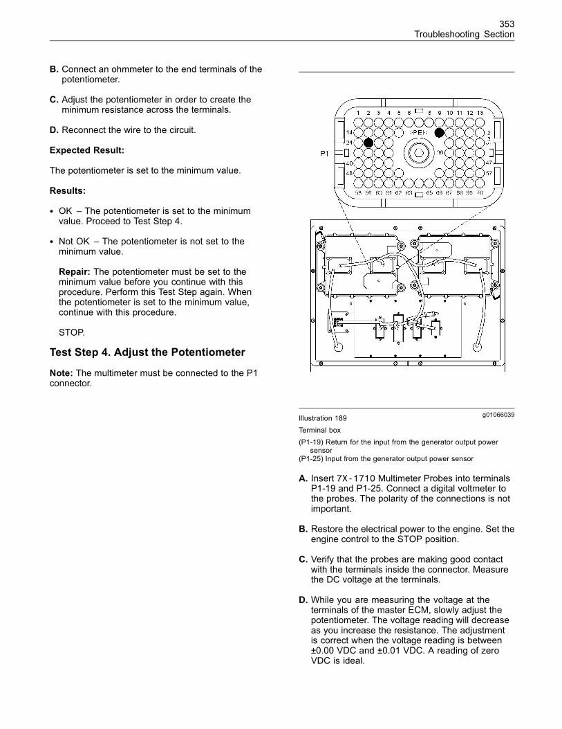
353Troubleshooting Section
B. Connect an ohmmeter to the end terminals of thepotentiometer.
C. Adjust the potentiometer in order to create theminimum resistance across the terminals.
D. Reconnect the wire to the circuit.
Expected Result:
The potentiometer is set to the minimum value.
Results:
• OK – The potentiometer is set to the minimumvalue. Proceed to Test Step 4.
• Not OK – The potentiometer is not set to theminimum value.
Repair: The potentiometer must be set to theminimum value before you continue with thisprocedure. Perform this Test Step again. Whenthe potentiometer is set to the minimum value,continue with this procedure.
STOP.
Test Step 4. Adjust the Potentiometer
Note: The multimeter must be connected to the P1connector.
g01066039Illustration 189Terminal box(P1-19) Return for the input from the generator output power
sensor(P1-25) Input from the generator output power sensor
A. Insert 7X-1710 Multimeter Probes into terminalsP1-19 and P1-25. Connect a digital voltmeter tothe probes. The polarity of the connections is notimportant.
B. Restore the electrical power to the engine. Set theengine control to the STOP position.
C. Verify that the probes are making good contactwith the terminals inside the connector. Measurethe DC voltage at the terminals.
D. While you are measuring the voltage at theterminals of the master ECM, slowly adjust thepotentiometer. The voltage reading will decreaseas you increase the resistance. The adjustmentis correct when the voltage reading is between±0.00 VDC and ±0.01 VDC. A reading of zeroVDC is ideal.
354Troubleshooting Section
Expected Result:
The voltage decreases as the potentiometer isadjusted. The final voltage is between ±0.0 VDC and±0.01 VDC.
Results:
• OK – The voltage is between ±0.0 VDC and±0.01 VDC. The calibration procedure has beencompleted successfully.
Repair: Adjust the “Power Monitoring” parameters.Refer to Systems Operation/Testing and Adjusting,“Electronic Control System Parameters”.
STOP.
• Not OK – The potentiometer cannot be adjustedin order to attain a DC voltage between ±0.0 VDCand ±0.01 VDC.
Repair: Replace the potentiometer and performthis entire procedure again.
STOP.
355Index Section
Index
Numerics
+5V Sensor Voltage Supply................................. 199+8V Sensor Voltage Supply................................. 206
A
Analog Sensor Signal .......................................... 214
C
Calibration Procedures ........................................ 349CAT Data Link ..................................................... 223Compressor Bypass ............................................ 229Customer Passwords ............................................ 27
D
Desired Speed Input (4 - 20 mA)......................... 235Detonation ............................................................. 36Probable Causes ............................................... 36Recommended Repairs ..................................... 37
Detonation Sensors ............................................. 239Diagnostic Codes .................................................. 65Active Diagnostic Codes .................................... 66Logged Diagnostic Codes.................................. 66
Diagnostic Functional Tests................................. 199Driven Equipment .................................................. 38Probable Causes ............................................... 38Recommended Repairs ..................................... 38
E
E004 Engine Overspeed Shutdown .................... 152E016 High Engine Coolant TemperatureShutdown........................................................... 152E017 High Engine Coolant TemperatureWarning ............................................................. 153E019 High Engine Oil Temperature Shutdown .... 153E020 High Engine Oil Temperature Warning....... 153E026 High Inlet Air Temperature Shutdown ........ 153E027 High Inlet Air Temperature Warning ........... 154E038 Low Engine Coolant TemperatureWarning ............................................................. 154E040 Low Engine Oil Pressure Shutdown........... 154E042 Low System Voltage Shutdown.................. 155E043 Low System Voltage Warning .................... 155E050 High System Voltage Warning ................... 155E053 Low Fuel Pressure Warning....................... 155E096 High Fuel Pressure .................................... 156E100 Low Engine Oil Pressure Warning ............. 156E127 Engine Oil Filter Diff Pressure LowWarning ............................................................. 156E128 Engine Oil Filter Diff Pressure LowShutdown........................................................... 156
E129 Engine Oil Filter Diff Pressure HighWarning ............................................................. 157E130 Engine Oil Filter Diff Pressure HighShutdown........................................................... 157E135 Low Jacket Water Pressure Shutdown ...... 157E223 High Gas Temperature............................... 158E224 High Jacket Water Inlet Pressure............... 158E225 Engine Overcrank ...................................... 158E226 Driven Equipment Not Ready..................... 158E229 Fuel Energy Content Setting Low .............. 159E230 Fuel Energy Content Setting High.............. 159E231 Fuel Quality Out of Range.......................... 159E243 High Left Turbo Turbine OutletTemperature....................................................... 159E244 High Right Turbo Turbine OutletTemperature....................................................... 160E245 High Right Turbo Turbine InletTemperature....................................................... 160E246 High Left Turbo Turbine Inlet Temperature.. 161E264 Emergency Stop Activated......................... 161E268 Unexpected Engine Shutdown................... 161E269 Customer Shutdown Requested ................ 161E270 Driven Equipment Shutdown Requested ... 162E337 High Engine Oil to Engine Coolant DiffTemp.................................................................. 162E401 Cylinder #1 Detonation............................... 163E402 Cylinder #2 Detonation............................... 163E403 Cylinder #3 Detonation............................... 163E404 Cylinder #4 Detonation............................... 163E405 Cylinder #5 Detonation............................... 164E406 Cylinder #6 Detonation............................... 164E407 Cylinder #7 Detonation............................... 164E408 Cylinder #8 Detonation............................... 164E409 Cylinder #9 Detonation............................... 165E410 Cylinder #10 Detonation............................. 165E411 Cylinder #11 Detonation ............................. 165E412 Cylinder #12 Detonation............................. 165E413 Cylinder #13 Detonation............................. 166E414 Cylinder #14 Detonation............................. 166E415 Cylinder #15 Detonation............................. 166E416 Cylinder #16 Detonation............................. 166E417 Cylinder #17 Detonation............................. 167E418 Cylinder #18 Detonation............................. 167E419 Cylinder #19 Detonation............................. 167E420 Cylinder #20 Detonation............................. 167E421 Cylinder #1 Detonation Shutdown.............. 168E422 Cylinder #2 Detonation Shutdown.............. 168E423 Cylinder #3 Detonation Shutdown.............. 168E424 Cylinder #4 Detonation Shutdown.............. 168E425 Cylinder #5 Detonation Shutdown.............. 169E426 Cylinder #6 Detonation Shutdown.............. 169E427 Cylinder #7 Detonation Shutdown.............. 169E428 Cylinder #8 Detonation Shutdown.............. 169E429 Cylinder #9 Detonation Shutdown.............. 170E430 Cylinder #10 Detonation Shutdown............ 170E431 Cylinder #11 Detonation Shutdown............ 170E432 Cylinder #12 Detonation Shutdown............ 171E433 Cylinder #13 Detonation Shutdown............ 171E434 Cylinder #14 Detonation Shutdown............ 171E435 Cylinder #15 Detonation Shutdown............ 171
356Index Section
E436 Cylinder #16 Detonation Shutdown............ 172E437 Cylinder #17 Detonation Shutdown............ 172E438 Cylinder #18 Detonation Shutdown............ 172E439 Cylinder #19 Detonation Shutdown............ 173E440 Cylinder #20 Detonation Shutdown............ 173E801 Cylinder #1 High Exhaust Port Temp ......... 173E802 Cylinder #2 High Exhaust Port Temp ......... 173E803 Cylinder #3 High Exhaust Port Temp ......... 174E804 Cylinder #4 High Exhaust Port Temp ......... 174E805 Cylinder #5 High Exhaust Port Temp ......... 175E806 Cylinder #6 High Exhaust Port Temp ......... 175E807 Cylinder #7 High Exhaust Port Temp ......... 175E808 Cylinder #8 High Exhaust Port Temp ......... 176E809 Cylinder #9 High Exhaust Port Temp ......... 176E810 Cylinder #10 High Exhaust Port Temp ....... 177E811 Cylinder #11 High Exhaust Port Temp........ 177E812 Cylinder #12 High Exhaust Port Temp ....... 177E813 Cylinder #13 High Exhaust Port Temp ....... 178E814 Cylinder #14 High Exhaust Port Temp ....... 178E815 Cylinder #15 High Exhaust Port Temp ....... 179E816 Cylinder #16 High Exhaust Port Temp ....... 179E817 Cylinder #17 High Exhaust Port Temp ....... 179E818 Cylinder #18 High Exhaust Port Temp ....... 180E819 Cylinder #19 High Exhaust Port Temp ....... 180E820 Cylinder #20 High Exhaust Port Temp ....... 180E821 Cyl #1 Exhaust Port Temp Deviating High.. 181E822 Cyl #2 Exhaust Port Temp Deviating High.. 181E823 Cyl #3 Exhaust Port Temp Deviating High.. 182E824 Cyl #4 Exhaust Port Temp Deviating High.. 182E825 Cyl #5 Exhaust Port Temp Deviating High.. 183E826 Cyl #6 Exhaust Port Temp Deviating High.. 183E827 Cyl #7 Exhaust Port Temp Deviating High.. 183E828 Cyl #8 Exhaust Port Temp Deviating High.. 184E829 Cyl #9 Exhaust Port Temp Deviating High.. 184E830 Cyl #10 Exhaust Port Temp DeviatingHigh ................................................................... 185E831 Cyl #11 Exhaust Port Temp DeviatingHigh ................................................................... 185E832 Cyl #12 Exhaust Port Temp DeviatingHigh ................................................................... 185E833 Cyl #13 Exhaust Port Temp DeviatingHigh ................................................................... 186E834 Cyl #14 Exhaust Port Temp DeviatingHigh ................................................................... 186E835 Cyl #15 Exhaust Port Temp DeviatingHigh ................................................................... 187E836 Cyl #16 Exhaust Port Temp DeviatingHigh ................................................................... 187E837 Cyl #17 Exhaust Port Temp DeviatingHigh ................................................................... 187E838 Cyl #18 Exhaust Port Temp DeviatingHigh ................................................................... 188E839 Cyl #19 Exhaust Port Temp DeviatingHigh ................................................................... 188E840 Cyl #20 Exhaust Port Temp DeviatingHigh ................................................................... 189E841 Cyl #1 Exhaust Port Temp Deviating Low.. 189E842 Cyl #2 Exhaust Port Temp Deviating Low.. 189E843 Cyl #3 Exhaust Port Temp Deviating Low.. 190E844 Cyl #4 Exhaust Port Temp Deviating Low.. 190E845 Cyl #5 Exhaust Port Temp Deviating Low.. 191
E846 Cyl #6 Exhaust Port Temp Deviating Low.. 191E847 Cyl #7 Exhaust Port Temp Deviating Low.. 191E848 Cyl #8 Exhaust Port Temp Deviating Low.. 192E849 Cyl #9 Exhaust Port Temp Deviating Low.. 192E850 Cyl #10 Exhaust Port Temp DeviatingLow .................................................................... 193E851 Cyl #11 Exhaust Port Temp Deviating Low.. 193E852 Cyl #12 Exhaust Port Temp DeviatingLow .................................................................... 193E853 Cyl #13 Exhaust Port Temp DeviatingLow .................................................................... 194E854 Cyl #14 Exhaust Port Temp DeviatingLow .................................................................... 194E855 Cyl #15 Exhaust Port Temp DeviatingLow .................................................................... 195E856 Cyl #16 Exhaust Port Temp DeviatingLow .................................................................... 195E857 Cyl #17 Exhaust Port Temp DeviatingLow .................................................................... 195E858 Cyl #18 Exhaust Port Temp DeviatingLow .................................................................... 196E859 Cyl #19 Exhaust Port Temp DeviatingLow .................................................................... 196E860 Cyl #20 Exhaust Port Temp DeviatingLow .................................................................... 197E864 Low Gas Fuel Differential Pressure ........... 197E865 High Gas Fuel Differential Pressure........... 197E866 Low Gas Fuel Flow Rate............................ 197E867 Improper Gas Flow Control ValveResponse........................................................... 198E868 Gas Flow Control Valve Malfunction .......... 198ECM Output Circuit (Fuel Control)....................... 248ECM Output Circuit (Starting Motor).................... 257ECM Status Indicator Output............................... 269ECM Will Not Accept Factory Passwords.............. 38Probable Causes ............................................... 38Recommended Repairs ..................................... 38
Electrical Connectors and Functions..................... 16Harness Wire Identification ................................ 16Junction Box ...................................................... 18Terminal Box ...................................................... 16
Electrical Power Supply....................................... 275Electronic Service Tool Will Not Communicate withECM (The Caterpillar Electronic Technician (ET)Will Not Communicate With an Electronic ControlModule (ECM) and/or the Integrated TemperatureSensing Module (ITSM))...................................... 38Probable Causes ............................................... 38Recommended Repairs ..................................... 39
Electronic Service Tools ........................................ 18Caterpillar Electronic Technician (ET)................ 19
Electronic Troubleshooting .................................... 10Engine Coolant Temperature (High) ...................... 39Probable Causes ............................................... 39Recommended Repairs ..................................... 39
Engine Coolant Temperature (Low)....................... 41Probable Causes ............................................... 41Recommended Repairs ..................................... 41
Engine Cranks but Will Not Start ........................... 41Probable Causes ............................................... 41Recommended Repairs ..................................... 41
357Index Section
Engine Misfires, Runs Rough or Is Unstable......... 42Probable Causes ............................................... 42Recommended Repairs ..................................... 42
Engine Monitoring System..................................... 20Changing the Settings of the MonitoringSystem ............................................................. 21Default Settings of the Monitoring System......... 22Monitoring Parameters....................................... 21Programmable Parameters of the IntegratedTemperature Sensing Module .......................... 25
Engine Oil Filter Differential Pressure ................... 44Probable Causes ............................................... 44Recommended Repairs ..................................... 44
Engine Oil Pressure (Low)..................................... 44Probable Causes ............................................... 44Recommended Repairs ..................................... 44
Engine Oil Temperature (High) .............................. 45Probable Causes ............................................... 45Recommended Repairs ..................................... 45
Engine Overcrank.................................................. 46Probable Causes ............................................... 46Recommended Repairs ..................................... 46
Engine Overload.................................................... 47Probable Causes ............................................... 47Recommended Repairs ..................................... 47
Engine Overspeed................................................. 47Probable Causes ............................................... 47Recommended Repairs ..................................... 47
Engine Shutdown .................................................. 48Probable Causes ............................................... 48Recommended Repairs ..................................... 48
Engine Shutdown (Unexpected)............................ 48Probable Causes ............................................... 48Recommended Repair ....................................... 48
Engine Shutdown without a Diagnostic Code........ 50Probable Causes ............................................... 50Recommended Repairs ..................................... 50
Engine Speed/Timing Sensor.............................. 282Engine Speed/Timing Sensor - Calibrate ............ 349Engine Starts but Stalls Immediately..................... 51Probable Causes ............................................... 51Recommended Repairs ..................................... 51
Engine Timing Does Not Match ProgrammedTiming .................................................................. 51Probable Causes ............................................... 51Recommended Repairs ..................................... 51
Engine Will Not Crank ........................................... 52Probable Causes ............................................... 52Recommended Repairs ..................................... 52
Event Codes........................................................ 150Active Event Codes.......................................... 151Diagnostic Codes and Event Codes ................ 151Logged Event Codes ....................................... 152Operator Information........................................ 151Other Symptoms.............................................. 151Troubleshooting ............................................... 151
Exhaust Port Temperature (High) .......................... 53Probable Causes ............................................... 53Recommended Repairs ..................................... 53
Exhaust Port Temperature (Low)........................... 54Probable Causes ............................................... 54Recommended Repairs ..................................... 54
F
Factory Passwords................................................ 27Factory Passwords Worksheet.............................. 28Flash Programming ............................................... 29Flash Programming............................................ 29
Fuel Energy Content.............................................. 55Probable Causes ............................................... 55Recommended Repairs ..................................... 55
Fuel Metering Valve....................................... 55, 289Probable Causes ............................................... 55Recommended Repairs ..................................... 55
Fuel Pressure ........................................................ 55Probable Causes ............................................... 55Recommended Repairs ..................................... 55
G
Gas Fuel Differential Pressure (High).................... 55Probable Causes ............................................... 55Recommended Repairs ..................................... 56
Gas Fuel Differential Pressure (Low) .................... 56Probable Causes ............................................... 56Recommended repairs....................................... 56
Gas Fuel Flow Rate (Low)..................................... 56Probable Causes ............................................... 56Recommended Repairs ..................................... 57
Gas Temperature (High) ........................................ 57Probable Causes ............................................... 57Recommended Repairs ..................................... 57
Generator Output Power Readings Do NotMatch................................................................... 58Probable Causes ............................................... 58Recommended Repairs ..................................... 58
Generator Output Power Sensor ......................... 298Generator Output Power Sensor - Calibrate ....... 351
I
Ignition Transformers Primary Circuit .................. 305Ignition Transformers Secondary Circuit and SparkPlugs.................................................................. 316Important Safety Information ................................... 2Inlet Air Temperature (High) .................................. 59Probable Causes ............................................... 59Recommended Repairs ..................................... 59
Inspecting Electrical Connectors ......................... 322Integrated Temperature Sensing Module(ITSM)................................................................ 327Intermittent Engine Shutdown ............................... 60Probable Causes ............................................... 60Recommended Repairs ..................................... 60
J
Jacket Water Inlet Pressure (High)........................ 60Probable Causes ............................................... 60Recommended Repairs ..................................... 61
358Index Section
Jacket Water Pressure (Low) ................................ 61Probable Causes ............................................... 61Recommended Repairs ..................................... 61
Jacket Water to Engine Oil Differential Temperature(Low).................................................................... 61Probable Causes ............................................... 61Recommended Repairs ..................................... 62
L
Location of Components........................................ 12Actuators............................................................ 12Fuel Metering Valve ........................................... 12Integrated Temperature Sensing Module........... 15Sensors.............................................................. 12Thermocouples .................................................. 14
M
MID 033 - CID 0041 - FMI 03 8 Volt DC Supply shortto +batt................................................................. 66MID 033 - CID 0041 - FMI 04 8 Volt DC Supply shortto ground.............................................................. 67MID 033 - CID 0168 - FMI 02 System Voltageintermittent/erratic ................................................ 67MID 033 - CID 0301 - FMI 05 Ignition TransformerPrimary #1 open circuit ........................................ 67MID 033 - CID 0301 - FMI 06 Ignition TransformerPrimary #1 short .................................................. 68MID 033 - CID 0303 - FMI 05 Ignition TransformerPrimary #3 open circuit ........................................ 68MID 033 - CID 0303 - FMI 06 Ignition TransformerPrimary #3 short .................................................. 68MID 033 - CID 0305 - FMI 05 Ignition TransformerPrimary #5 open circuit ........................................ 69MID 033 - CID 0305 - FMI 06 Ignition TransformerPrimary #5 short .................................................. 69MID 033 - CID 0307 - FMI 05 Ignition TransformerPrimary #7 open circuit ........................................ 69MID 033 - CID 0307 - FMI 06 Ignition TransformerPrimary #7 short .................................................. 70MID 033 - CID 0309 - FMI 05 Ignition TransformerPrimary #9 open circuit ........................................ 70MID 033 - CID 0309 - FMI 06 Ignition TransformerPrimary #9 short .................................................. 71MID 033 - CID 0311 - FMI 05 Ignition TransformerPrimary #11 open circuit ...................................... 71MID 033 - CID 0311 - FMI 06 Ignition TransformerPrimary #11 short................................................. 71MID 033 - CID 0313 - FMI 05 Ignition TransformerPrimary #13 open circuit ...................................... 72MID 033 - CID 0313 - FMI 06 Ignition TransformerPrimary #13 short ................................................ 72MID 033 - CID 0315 - FMI 05 Ignition TransformerPrimary #15 open circuit ...................................... 72MID 033 - CID 0315 - FMI 06 Ignition TransformerPrimary #15 short ................................................ 73MID 033 - CID 0320 - FMI 03 Speed/Timing Sensorshort to +batt........................................................ 73
MID 033 - CID 0320 - FMI 08 Engine Speed/Timingsignal abnormal ................................................... 74MID 033 - CID 0401 - FMI 05 Ignition TransformerSecondary #1 open circuit ................................... 74MID 033 - CID 0401 - FMI 06 Ignition TransformerSecondary #1 short to ground ............................. 74MID 033 - CID 0403 - FMI 05 Ignition TransformerSecondary #3 open circuit ................................... 75MID 033 - CID 0403 - FMI 06 Ignition TransformerSecondary #3 short to ground ............................. 75MID 033 - CID 0405 - FMI 05 Ignition TransformerSecondary #5 open circuit ................................... 75MID 033 - CID 0405 - FMI 06 Ignition TransformerSecondary #5 short to ground ............................. 76MID 033 - CID 0407 - FMI 05 Ignition TransformerSecondary #7 open circuit ................................... 76MID 033 - CID 0407 - FMI 06 Ignition TransformerSecondary #7 short to ground ............................. 77MID 033 - CID 0409 - FMI 05 Ignition TransformerSecondary #9 open circuit ................................... 77MID 033 - CID 0409 - FMI 06 Ignition TransformerSecondary #9 short to ground ............................. 77MID 033 - CID 0411 - FMI 05 Ignition TransformerSecondary #11 open circuit ................................. 78MID 033 - CID 0411 - FMI 06 Ignition TransformerSecondary #11 short to ground............................ 78MID 033 - CID 0413 - FMI 05 Ignition TransformerSecondary #13 open circuit ................................. 79MID 033 - CID 0413 - FMI 06 Ignition TransformerSecondary #13 short to ground ........................... 79MID 033 - CID 0415 - FMI 05 Ignition TransformerSecondary #15 open circuit ................................. 79MID 033 - CID 0415 - FMI 06 Ignition TransformerSecondary #15 short to ground ........................... 80MID 033 - CID 0590 - FMI 09 Unable to communicatewith Engine ECM ................................................. 80MID 033 - CID 1501 - FMI 03 Cylinder #1 DetonationSensor open/short to +batt .................................. 81MID 033 - CID 1501 - FMI 04 Cylinder #1 DetonationSensor short to ground ........................................ 81MID 033 - CID 1505 - FMI 03 Cylinder #5 DetonationSensor open/short to +batt .................................. 81MID 033 - CID 1505 - FMI 04 Cylinder #5 DetonationSensor short to ground ........................................ 82MID 033 - CID 1509 - FMI 03 Cylinder #9 DetonationSensor open/short to +batt .................................. 82MID 033 - CID 1509 - FMI 04 Cylinder #9 DetonationSensor short to ground ........................................ 82MID 033 - CID 1513 - FMI 03 Cylinder #13 DetonationSensor open/short to +batt .................................. 83MID 033 - CID 1513 - FMI 04 Cylinder #13 DetonationSensor short to ground ........................................ 83MID 033 - CID 1517 - FMI 03 Cylinder #17 DetonationSensor open/short to +batt .................................. 83MID 033 - CID 1517 - FMI 04 Cylinder #17 DetonationSensor short to ground ........................................ 84MID 033 - CID 1748 - FMI 05 Ignition TransformerSecondary #17 open circuit ................................. 84MID 033 - CID 1748 - FMI 06 Ignition TransformerSecondary #17 short to ground ........................... 84
359Index Section
MID 033 - CID 1750 - FMI 05 Ignition TransformerSecondary #19 open circuit ................................. 85MID 033 - CID 1750 - FMI 06 Ignition TransformerSecondary #19 short to ground ........................... 85MID 033 - CID 1752 - FMI 05 Ignition TransformerPrimary #17 open circuit ...................................... 85MID 033 - CID 1752 - FMI 06 Ignition TransformerPrimary #17 short to ground ................................ 86MID 033 - CID 1754 - FMI 05 Ignition TransformerPrimary #19 open circuit ...................................... 86MID 033 - CID 1754 - FMI 06 Ignition TransformerPrimary #19 short to ground ................................ 87MID 036 - CID 0017 - FMI 05 Fuel Shutoff Valve opencircuit ................................................................... 87MID 036 - CID 0017 - FMI 06 Fuel Shutoff Valve shortto ground.............................................................. 87MID 036 - CID 0017 - FMI 12 Fuel Shutoff Valvemalfunction .......................................................... 88MID 036 - CID 0041 - FMI 03 8 Volt DC Supply shortto +batt................................................................. 88MID 036 - CID 0041 - FMI 04 8 Volt DC Supply shortto ground.............................................................. 88MID 036 - CID 0100 - FMI 03 Engine Oil Pressureopen/short to +batt............................................... 89MID 036 - CID 0100 - FMI 04 Engine Oil Pressureshort to ground..................................................... 89MID 036 - CID 0106 - FMI 03 Air Inlet PressureSensor short to +batt ........................................... 90MID 036 - CID 0106 - FMI 08 Air Inlet PressureSensor noisy signal.............................................. 90MID 036 - CID 0109 - FMI 03 Coolant Outlet Pressureopen/short to +batt............................................... 90MID 036 - CID 0109 - FMI 08 Engine Coolant OutletPressure Sensor noisy signal .............................. 91MID 036 - CID 0110 - FMI 03 Engine CoolantTemperature open/short to +batt ......................... 91MID 036 - CID 0110 - FMI 04 Engine CoolantTemperature short to ground ............................... 91MID 036 - CID 0145 - FMI 03 12 Volt DC PowerSupply short to +batt............................................ 92MID 036 - CID 0145 - FMI 04 12 Volt DC PowerSupply short to ground......................................... 92MID 036 - CID 0168 - FMI 02 System Voltageintermittent/erratic ................................................ 92MID 036 - CID 0172 - FMI 03 Intake Manifold AirTemp open/short to +batt..................................... 93MID 036 - CID 0172 - FMI 04 Intake Manifold AirTemp short to ground........................................... 93MID 036 - CID 0175 - FMI 03 Engine Oil Temperatureopen/short to +batt............................................... 93MID 036 - CID 0175 - FMI 04 Engine Oil Temperatureshort to ground..................................................... 94MID 036 - CID 0261 - FMI 13 Engine Timingcalibration required .............................................. 94MID 036 - CID 0262 - FMI 03 5 Volt Sensor DCPower Supply short to +batt ................................ 95MID 036 - CID 0262 - FMI 04 5 Volt Sensor DCPower Supply short to ground ............................. 95MID 036 - CID 0302 - FMI 05 Ignition TransformerPrimary #2 open circuit ........................................ 96MID 036 - CID 0302 - FMI 06 Ignition TransformerPrimary #2 short .................................................. 96
MID 036 - CID 0304 - FMI 05 Ignition TransformerPrimary #4 open circuit ........................................ 96MID 036 - CID 0304 - FMI 06 Ignition TransformerPrimary #4 short .................................................. 97MID 036 - CID 0306 - FMI 05 Ignition TransformerPrimary #6 open circuit ........................................ 97MID 036 - CID 0306 - FMI 06 Ignition TransformerPrimary #6 short .................................................. 97MID 036 - CID 0308 - FMI 05 Ignition TransformerPrimary #8 open circuit ........................................ 98MID 036 - CID 0308 - FMI 06 Ignition TransformerPrimary #8 short .................................................. 98MID 036 - CID 0310 - FMI 05 Ignition TransformerPrimary #10 open circuit ...................................... 98MID 036 - CID 0310 - FMI 06 Ignition TransformerPrimary #10 short ................................................ 99MID 036 - CID 0312 - FMI 05 Ignition TransformerPrimary #12 open circuit ...................................... 99MID 036 - CID 0312 - FMI 06 Ignition TransformerPrimary #12 short .............................................. 100MID 036 - CID 0314 - FMI 05 Ignition TransformerPrimary #14 open circuit .................................... 100MID 036 - CID 0314 - FMI 06 Ignition TransformerPrimary #14 short .............................................. 100MID 036 - CID 0316 - FMI 05 Ignition TransformerPrimary #16 open circuit .................................... 101MID 036 - CID 0316 - FMI 06 Ignition TransformerPrimary #16 short .............................................. 101MID 036 - CID 0320 - FMI 03 Speed/Timing Sensorshort to +batt...................................................... 101MID 036 - CID 0320 - FMI 08 Engine Speed/Timingsignal abnormal ................................................. 102MID 036 - CID 0323 - FMI 03 Shutdown Lamp shortto +batt............................................................... 102MID 036 - CID 0324 - FMI 03 Warning Lamp short to+batt................................................................... 102MID 036 - CID 0336 - FMI 02 Incorrect ECS Switchinputs ................................................................. 103MID 036 - CID 0402 - FMI 05 Ignition TransformerSecondary #2 open circuit ................................. 103MID 036 - CID 0402 - FMI 06 Ignition TransformerSecondary #2 short to ground ........................... 103MID 036 - CID 0404 - FMI 05 Ignition TransformerSecondary #4 open circuit ................................. 104MID 036 - CID 0404 - FMI 06 Ignition TransformerSecondary #4 short to ground ........................... 104MID 036 - CID 0406 - FMI 05 Ignition TransformerSecondary #6 open circuit ................................. 105MID 036 - CID 0406 - FMI 06 Ignition TransformerSecondary #6 short to ground ........................... 105MID 036 - CID 0408 - FMI 05 Ignition TransformerSecondary #8 open circuit ................................. 105MID 036 - CID 0408 - FMI 06 Ignition TransformerSecondary #8 short to ground ........................... 106MID 036 - CID 0410 - FMI 05 Ignition TransformerSecondary #10 open circuit ............................... 106MID 036 - CID 0410 - FMI 06 Ignition TransformerSecondary #10 short to ground ......................... 107MID 036 - CID 0412 - FMI 05 Ignition TransformerSecondary #12 open circuit ............................... 107MID 036 - CID 0412 - FMI 06 Ignition TransformerSecondary #12 short to ground ......................... 107
360Index Section
MID 036 - CID 0414 - FMI 05 Ignition TransformerSecondary #14 open circuit ............................... 108MID 036 - CID 0414 - FMI 06 Ignition TransformerSecondary #14 short to ground ......................... 108MID 036 - CID 0416 - FMI 05 Ignition TransformerSecondary #16 open circuit ............................... 108MID 036 - CID 0416 - FMI 06 Ignition TransformerSecondary #16 short to ground ......................... 109MID 036 - CID 0443 - FMI 03 Crank Terminate Relayshort to +batt...................................................... 109MID 036 - CID 0444 - FMI 05 Start Relay opencircuit .................................................................. 110MID 036 - CID 0444 - FMI 06 Start Relay short toground................................................................. 110MID 036 - CID 0445 - FMI 03 Run Relay short to+batt.................................................................... 110MID 036 - CID 0524 - FMI 03 Desired Engine SpeedSensor short to +batt .......................................... 111MID 036 - CID 0524 - FMI 04 Desired Engine SpeedSensor short to ground ....................................... 111MID 036 - CID 0542 - FMI 03 Unfiltered Engine OilPressure open/short to +batt .............................. 111MID 036 - CID 0542 - FMI 04 Unfiltered Engine OilPressure short to ground .................................... 112MID 036 - CID 1042 - FMI 09 Unable to communicatewith ITSM............................................................ 112MID 036 - CID 1440 - FMI 09 Unable to communicatewith Throttle Actuator Drv ................................... 113MID 036 - CID 1446 - FMI 05 Fuel Metering Moduleopen circuit ......................................................... 113MID 036 - CID 1446 - FMI 09 Unable to communicatewith Fuel Metering Module.................................. 113MID 036 - CID 1446 - FMI 12 Fuel Metering Modulemalfunction ......................................................... 114MID 036 - CID 1446 - FMI 13 Fuel Metering Modulecalibration required ............................................. 114MID 036 - CID 1447 - FMI 12 Fuel Metering SensorModule malfunction............................................. 114MID 036 - CID 1502 - FMI 03 Cylinder #2 DetonationSensor open/short to +batt ................................. 114MID 036 - CID 1502 - FMI 04 Cylinder #2 DetonationSensor short to ground ....................................... 115MID 036 - CID 1506 - FMI 03 Cylinder #6 DetonationSensor open/short to +batt ................................. 115MID 036 - CID 1506 - FMI 04 Cylinder #6 DetonationSensor short to ground ....................................... 115MID 036 - CID 1510 - FMI 03 Cylinder #10 DetonationSensor open/short to +batt ................................. 116MID 036 - CID 1510 - FMI 04 Cylinder #10 DetonationSensor short to ground ....................................... 116MID 036 - CID 1514 - FMI 03 Cylinder #14 DetonationSensor open/short to +batt ................................. 116MID 036 - CID 1514 - FMI 04 Cylinder #14 DetonationSensor short to ground ....................................... 117MID 036 - CID 1518 - FMI 03 Cylinder #18 DetonationSensor open/short to +batt ................................. 117MID 036 - CID 1518 - FMI 04 Cylinder #18 DetonationSensor short to ground ....................................... 117MID 036 - CID 1636 - FMI 09 Loss of Communicationwith Engine #2 (Slave)........................................ 118
MID 036 - CID 1719 - FMI 03 Generator OutputPower Sensor open/short to +batt ...................... 118MID 036 - CID 1719 - FMI 04 Generator OutputPower Sensor short to ground............................ 118MID 036 - CID 1719 - FMI 12 Generator OutputPower Sensor malfunction.................................. 119MID 036 - CID 1720 - FMI 09 TurbochargerCompressor Bypass Valve Actuator notcommunicating on link ........................................ 119MID 036 - CID 1749 - FMI 05 Ignition TransformerSecondary #18 open circuit ................................ 119MID 036 - CID 1749 - FMI 06 Ignition TransformerSecondary #18 short to ground ......................... 120MID 036 - CID 1751 - FMI 05 Ignition TransformerSecondary #20 open circuit ............................... 120MID 036 - CID 1751 - FMI 06 Ignition TransformerSecondary #20 short to ground ......................... 120MID 036 - CID 1753 - FMI 05 Ignition TransformerPrimary #18 open circuit .................................... 121MID 036 - CID 1753 - FMI 06 Ignition TransformerPrimary #18 short to ground .............................. 121MID 036 - CID 1755 - FMI 05 Ignition TransformerPrimary #20 open circuit .................................... 121MID 036 - CID 1755 - FMI 06 Ignition TransformerPrimary #20 short to ground .............................. 122MID 111 - CID 0591 - FMI 12 EEPROM checksumfault or ECM not programmed ........................... 122MID 111 - CID 1489 - FMI 03 Left Turbo Turbine OutTemp Sens short to +batt................................... 122MID 111 - CID 1489 - FMI 04 Left Turbo Turbine OutTemp Sens short to ground................................ 123MID 111 - CID 1489 - FMI 05 Left Turbo Turbine OutTemp Sens open circuit ..................................... 123MID 111 - CID 1490 - FMI 03 Rt Turbo Turbine OutTemp Sens short to +batt................................... 123MID 111 - CID 1490 - FMI 04 Rt Turbo Turbine OutTemp Sens short to ground................................ 124MID 111 - CID 1490 - FMI 05 Rt Turbo Turbine OutTemp Sens open circuit ..................................... 124MID 111 - CID 1491 - FMI 03 Rt Turbo Turbine InTemp Sens short to +batt................................... 124MID 111 - CID 1491 - FMI 04 Rt Turbo Turbine InTemp Sens short to ground................................ 125MID 111 - CID 1491 - FMI 05 Rt Turbo Turbine InTemp Sens open circuit ..................................... 125MID 111 - CID 1492 - FMI 03 Left Turbo Turbine InTemp Sens short to +batt................................... 125MID 111 - CID 1492 - FMI 04 Left Turbo Turbine InTemp Sens short to ground................................ 126MID 111 - CID 1492 - FMI 05 Left Turbo Turbine InTemp Sens open circuit ..................................... 126MID 111 - CID 1531 - FMI 03 Cyl #1 Exhaust PortTemp Sensor short to +batt ............................... 126MID 111 - CID 1531 - FMI 04 Cyl #1 Exhaust PortTemp Sensor short to ground ............................ 127MID 111 - CID 1531 - FMI 05 Cyl #1 Exhaust PortTemp Sensor open circuit .................................. 127MID 111 - CID 1532 - FMI 03 Cyl #2 Exhaust PortTemp Sensor short to +batt ............................... 127MID 111 - CID 1532 - FMI 04 Cyl #2 Exhaust PortTemp Sensor short to ground ............................ 128
361Index Section
MID 111 - CID 1532 - FMI 05 Cyl #2 Exhaust PortTemp Sensor open circuit .................................. 128MID 111 - CID 1533 - FMI 03 Cyl #3 Exhaust PortTemp Sensor short to +batt ............................... 129MID 111 - CID 1533 - FMI 04 Cyl #3 Exhaust PortTemp Sensor short to ground ............................ 129MID 111 - CID 1533 - FMI 05 Cyl #3 Exhaust PortTemp Sensor open circuit .................................. 129MID 111 - CID 1534 - FMI 03 Cyl #4 Exhaust PortTemp Sensor short to +batt ............................... 130MID 111 - CID 1534 - FMI 04 Cyl #4 Exhaust PortTemp Sensor short to ground ............................ 130MID 111 - CID 1534 - FMI 05 Cyl #4 Exhaust PortTemp Sensor open circuit .................................. 130MID 111 - CID 1535 - FMI 03 Cyl #5 Exhaust PortTemp Sensor short to +batt ............................... 131MID 111 - CID 1535 - FMI 04 Cyl #5 Exhaust PortTemp Sensor short to ground ............................ 131MID 111 - CID 1535 - FMI 05 Cyl #5 Exhaust PortTemp Sensor open circuit .................................. 132MID 111 - CID 1536 - FMI 03 Cyl #6 Exhaust PortTemp Sensor short to +batt ............................... 132MID 111 - CID 1536 - FMI 04 Cyl #6 Exhaust PortTemp Sensor short to ground ............................ 132MID 111 - CID 1536 - FMI 05 Cyl #6 Exhaust PortTemp Sensor open circuit .................................. 133MID 111 - CID 1537 - FMI 03 Cyl #7 Exhaust PortTemp Sensor short to +batt ............................... 133MID 111 - CID 1537 - FMI 04 Cyl #7 Exhaust PortTemp Sensor short to ground ............................ 133MID 111 - CID 1537 - FMI 05 Cyl #7 Exhaust PortTemp Sensor open circuit .................................. 134MID 111 - CID 1538 - FMI 03 Cyl #8 Exhaust PortTemp Sensor short to +batt ............................... 134MID 111 - CID 1538 - FMI 04 Cyl #8 Exhaust PortTemp Sensor short to ground ............................ 135MID 111 - CID 1538 - FMI 05 Cyl #8 Exhaust PortTemp Sensor open circuit .................................. 135MID 111 - CID 1539 - FMI 03 Cyl #9 Exhaust PortTemp Sensor short to +batt ............................... 135MID 111 - CID 1539 - FMI 04 Cyl #9 Exhaust PortTemp Sensor short to ground ............................ 136MID 111 - CID 1539 - FMI 05 Cyl #9 Exhaust PortTemp Sensor open circuit .................................. 136MID 111 - CID 1540 - FMI 03 Cyl #10 Exhaust PortTemp Sensor short to +batt ............................... 136MID 111 - CID 1540 - FMI 04 Cyl #10 Exhaust PortTemp Sensor short to ground ............................ 137MID 111 - CID 1540 - FMI 05 Cyl #10 Exhaust PortTemp Sensor open circuit .................................. 137MID 111 - CID 1541 - FMI 03 Cyl #11 Exhaust PortTemp Sensor short to +batt ............................... 138MID 111 - CID 1541 - FMI 04 Cyl #11 Exhaust PortTemp Sensor short to ground ............................ 138MID 111 - CID 1541 - FMI 05 Cyl #11 Exhaust PortTemp Sensor open circuit .................................. 138MID 111 - CID 1542 - FMI 03 Cyl #12 Exhaust PortTemp Sensor short to +batt ............................... 139MID 111 - CID 1542 - FMI 04 Cyl #12 Exhaust PortTemp Sensor short to ground ............................ 139MID 111 - CID 1542 - FMI 05 Cyl #12 Exhaust PortTemp Sensor open circuit .................................. 139
MID 111 - CID 1543 - FMI 03 Cyl #13 Exhaust PortTemp Sensor short to +batt ............................... 140MID 111 - CID 1543 - FMI 04 Cyl #13 Exhaust PortTemp Sensor short to ground ............................ 140MID 111 - CID 1543 - FMI 05 Cyl #13 Exhaust PortTemp Sensor open circuit .................................. 141MID 111 - CID 1544 - FMI 03 Cyl #14 Exhaust PortTemp Sensor short to +batt ............................... 141MID 111 - CID 1544 - FMI 04 Cyl #14 Exhaust PortTemp Sensor short to ground ............................ 141MID 111 - CID 1544 - FMI 05 Cyl #14 Exhaust PortTemp Sensor open circuit .................................. 142MID 111 - CID 1545 - FMI 03 Cyl #15 Exhaust PortTemp Sensor short to +batt ............................... 142MID 111 - CID 1545 - FMI 04 Cyl #15 Exhaust PortTemp Sensor short to ground ............................ 142MID 111 - CID 1545 - FMI 05 Cyl #15 Exhaust PortTemp Sensor open circuit .................................. 143MID 111 - CID 1546 - FMI 03 Cyl #16 Exhaust PortTemp Sensor short to +batt ............................... 143MID 111 - CID 1546 - FMI 04 Cyl #16 Exhaust PortTemp Sensor short to ground ............................ 144MID 111 - CID 1546 - FMI 05 Cyl #16 Exhaust PortTemp Sensor open circuit .................................. 144MID 111 - CID 1547 - FMI 03 Cyl #17 Exhaust PortTemp Sensor short to +batt ............................... 144MID 111 - CID 1547 - FMI 04 Cyl #17 Exhaust PortTemp Sensor short to ground ............................ 145MID 111 - CID 1547 - FMI 05 Cyl #17 Exhaust PortTemp Sensor open circuit .................................. 145MID 111 - CID 1548 - FMI 03 Cyl #18 Exhaust PortTemp Sensor short to +batt ............................... 145MID 111 - CID 1548 - FMI 04 Cyl #18 Exhaust PortTemp Sensor short to ground ............................ 146MID 111 - CID 1548 - FMI 05 Cyl #18 Exhaust PortTemp Sensor open circuit .................................. 146MID 111 - CID 1549 - FMI 03 Cyl #19 Exhaust PortTemp Sensor short to +batt ............................... 147MID 111 - CID 1549 - FMI 04 Cyl #19 Exhaust PortTemp Sensor short to ground ............................ 147MID 111 - CID 1549 - FMI 05 Cyl #19 Exhaust PortTemp Sensor open circuit .................................. 147MID 111 - CID 1550 - FMI 03 Cyl #20 Exhaust PortTemp Sensor short to +batt ............................... 148MID 111 - CID 1550 - FMI 04 Cyl #20 Exhaust PortTemp Sensor short to ground ............................ 148MID 111 - CID 1550 - FMI 05 Cyl #20 Exhaust PortTemp Sensor open circuit .................................. 148
P
Programming Parameters ..................................... 27PWM Sensor ....................................................... 335
R
Replacing the ECM................................................ 30Replacing the ITSM............................................... 32
362Index Section
S
Self-Diagnostics...................................................... 11Symptoms.............................................................. 36Diagnostic Codes and Event Codes .................. 36Operator Information.......................................... 36Other Symptoms................................................ 36
System Configuration Parameters......................... 29System Overview................................................... 10Air/Fuel Ratio Control......................................... 10Engine Monitoring and Protection....................... 11Engine Speed Governing................................... 10Ignition Control.................................................... 11Introduction ........................................................ 10Start/Stop Sequencing ....................................... 10
System Voltage...................................................... 62Probable Causes ............................................... 62Recommended Repairs ..................................... 62
T
Table of Contents..................................................... 3Throttle Actuator .................................................. 342Troubleshooting Data Sheet.................................. 34Report the Service Information .......................... 35
Troubleshooting Section........................................ 10Troubleshooting with a Diagnostic Code ............... 65Troubleshooting with an Event Code................... 150Troubleshooting without a Diagnostic Code .......... 36Turbocharger Turbine Temperature (High) ............ 62Probable Causes ............................................... 62Recommended Repairs ..................................... 62
Turbocharger Turbine Temperature (Low)............. 63Probable Causes ............................................... 63Recommended Repairs ..................................... 63

363Index Section

©2004 CaterpillarAll Rights Reserved Printed in U.S.A.