G3-PLC (CENELEC Band) Data Concentrator Reference … · It includes advanced hardware and ......
12
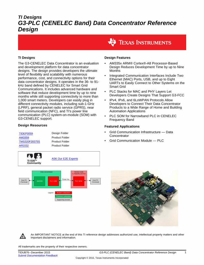
Data concentrator AM3359 PLC SOM Host PC (Terminal) Service node ½ TMDSPLCKITV4 PLC SOM Host PC (Terminal) Power line Legend: Modem subsystem Processor subsystem Supporting function TI Designs G3-PLC (CENELEC Band) Data Concentrator Reference Design TI Designs Design Features The G3-CENELEC Data Concentrator is an evaluation • AM335x ARM® Cortex®-A8 Processor-Based and development platform for data concentrator Design Reduces Development Time by up to Nine designs. The design provides developers the ultimate Months level of flexibility and scalability with numerous • Integrated Communication Interfaces Include Two performance, cost, and connectivity options for their Ethernet (MAC) Ports, USB, and up to Eight data concentrator designs. It operates in the 36- to 91- UARTs to Easily Connect to Other Systems on the kHz band defined by CENELEC for Smart Grid Smart Grid Communications. It includes advanced hardware and • PLC Stacks for MAC and PHY Layers Let software that reduce development time by up to nine Developers Create Designs That Support G3-FCC months while still supporting connectivity to more than • IPv4, IPv6, and 6LoWPAN Protocols Allow 1,000 smart meters. Developers can easily plug in Developers to Connect Their Data Concentrator different connectivity modules, including sub-1-GHz Products to a Wide Range of Home and Building (LPRF), general packet radio service (GPRS), near Automation Applications field communication (NFC), and TI's power line communication (PLC) system-on-module (SOM) with • PLC SOM for Narrowband PLC in CENELEC G3-CENELEC support. Frequency Band Design Resources Featured Applications • Grid Communication Infrastructure — Data Design Folder TIDEP0059 Concentrator AM3359 Product Folder • Grid Communication Module — PLC TMS320F28375S Product Folder AFE032 Product Folder ASK Our E2E Experts An IMPORTANT NOTICE at the end of this TI reference design addresses authorized use, intellectual property matters and other important disclaimers and information. All trademarks are the property of their respective owners. 1 TIDUB76 – December 2015 G3-PLC (CENELEC Band) Data Concentrator Reference Design Submit Documentation Feedback Copyright © 2015, Texas Instruments Incorporated
-
Upload
phungkhuong -
Category
Documents
-
view
223 -
download
0
Transcript of G3-PLC (CENELEC Band) Data Concentrator Reference … · It includes advanced hardware and ......
Data concentrator
AM3359 PLC SOMHost PC
(Terminal)
Service node½ TMDSPLCKITV4
PLC SOMHost PC
(Terminal)
Power line
Legend: Modem subsystem
Processor subsystem
Supporting function
TI DesignsG3-PLC (CENELEC Band) Data Concentrator ReferenceDesign
TI Designs Design FeaturesThe G3-CENELEC Data Concentrator is an evaluation • AM335x ARM® Cortex®-A8 Processor-Basedand development platform for data concentrator Design Reduces Development Time by up to Ninedesigns. The design provides developers the ultimate Monthslevel of flexibility and scalability with numerous • Integrated Communication Interfaces Include Twoperformance, cost, and connectivity options for their Ethernet (MAC) Ports, USB, and up to Eightdata concentrator designs. It operates in the 36- to 91- UARTs to Easily Connect to Other Systems on thekHz band defined by CENELEC for Smart Grid Smart GridCommunications. It includes advanced hardware and
• PLC Stacks for MAC and PHY Layers Letsoftware that reduce development time by up to nineDevelopers Create Designs That Support G3-FCCmonths while still supporting connectivity to more than
• IPv4, IPv6, and 6LoWPAN Protocols Allow1,000 smart meters. Developers can easily plug inDevelopers to Connect Their Data Concentratordifferent connectivity modules, including sub-1-GHzProducts to a Wide Range of Home and Building(LPRF), general packet radio service (GPRS), nearAutomation Applicationsfield communication (NFC), and TI's power line
communication (PLC) system-on-module (SOM) with • PLC SOM for Narrowband PLC in CENELECG3-CENELEC support. Frequency Band
Design Resources Featured Applications• Grid Communication Infrastructure — DataDesign FolderTIDEP0059
ConcentratorAM3359 Product Folder• Grid Communication Module — PLCTMS320F28375S Product Folder
AFE032 Product Folder
ASK Our E2E Experts
An IMPORTANT NOTICE at the end of this TI reference design addresses authorized use, intellectual property matters and otherimportant disclaimers and information.
All trademarks are the property of their respective owners.
1TIDUB76–December 2015 G3-PLC (CENELEC Band) Data Concentrator Reference DesignSubmit Documentation Feedback
Copyright © 2015, Texas Instruments Incorporated
System Description www.ti.com
1 System DescriptionThis TI Design is an evaluation and development platform for data concentrator designs based on theAM335x ARM Cortex-A8 microprocessor family of devices. The board can interface with multiple nodes(electricity meter) though PLC, low-power RF, or serially using RS-485. All of the board design informationis freely available and can be used as the starting point for an AM335x-based data concentrator product.For more details of hardware, see the Smart Data Concentrator EVM (TMDSDC3359) Hardware Manual[1].
Data concentrators play a key role in advanced metering infrastructure (AMI) networks as they are thepoint of interaction between the utility’s central operations and individual end points. The data concentratornodes securely aggregate data from a network of meters over the power line and send it to utility servers.
Data concentrator software architecture separates the real-time functions into the TMS320F28375S MCUwhile keeping the upper levels of the stack on the AM335x host MPU running Linux.
2 G3-PLC (CENELEC Band) Data Concentrator Reference Design TIDUB76–December 2015Submit Documentation Feedback
Copyright © 2015, Texas Instruments Incorporated
www.ti.com Block Diagram
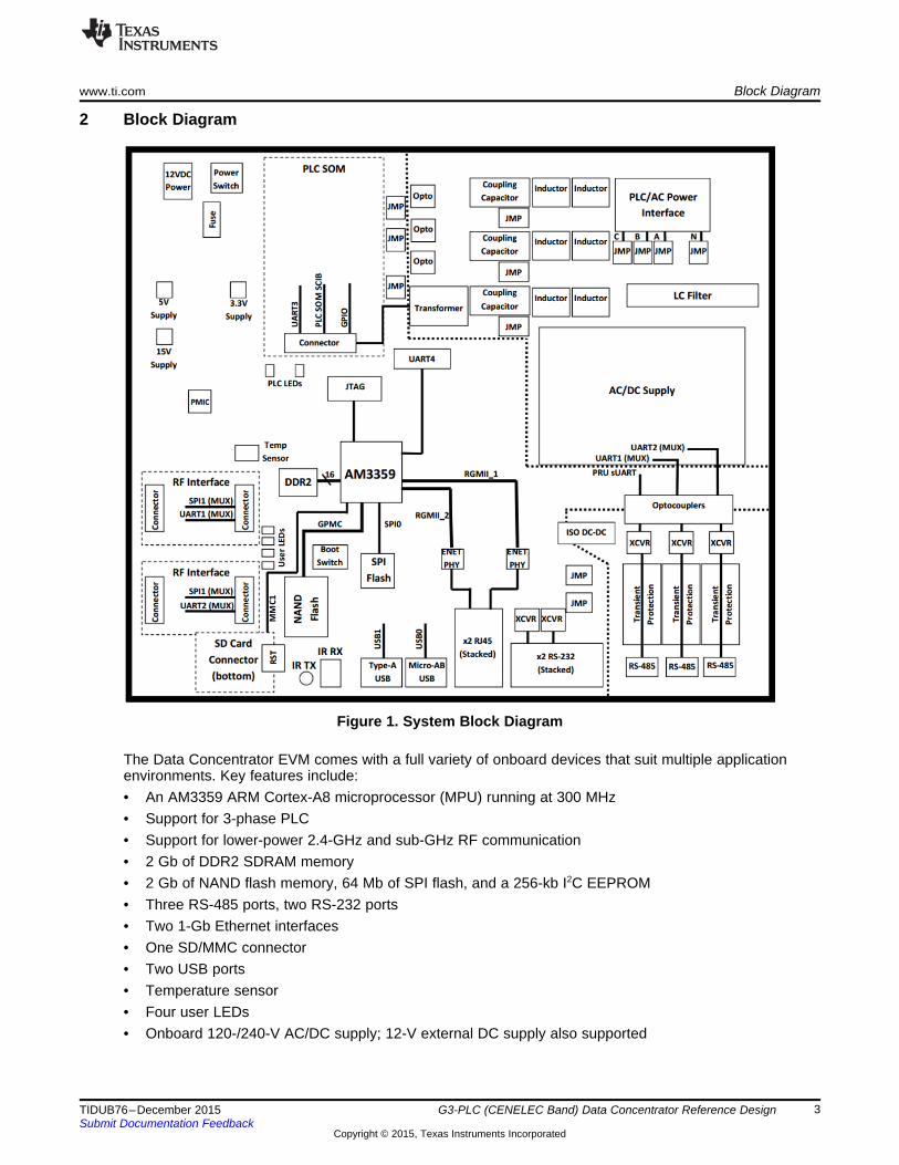
2 Block Diagram
Figure 1. System Block Diagram
The Data Concentrator EVM comes with a full variety of onboard devices that suit multiple applicationenvironments. Key features include:• An AM3359 ARM Cortex-A8 microprocessor (MPU) running at 300 MHz• Support for 3-phase PLC• Support for lower-power 2.4-GHz and sub-GHz RF communication• 2 Gb of DDR2 SDRAM memory• 2 Gb of NAND flash memory, 64 Mb of SPI flash, and a 256-kb I2C EEPROM• Three RS-485 ports, two RS-232 ports• Two 1-Gb Ethernet interfaces• One SD/MMC connector• Two USB ports• Temperature sensor• Four user LEDs• Onboard 120-/240-V AC/DC supply; 12-V external DC supply also supported
3TIDUB76–December 2015 G3-PLC (CENELEC Band) Data Concentrator Reference DesignSubmit Documentation Feedback
Copyright © 2015, Texas Instruments Incorporated
System Design Theory www.ti.com
3 System Design TheoryThe Data Concentrator EVM consists of one main PCB assembly housing the AM3359 Cortex-A8processor, DDR2 memory, NAND flash, and other peripherals. The AM3359 processor interfaces to theonboard peripherals through its integrated device interfaces. The processor's DDR 16-bit bus connectsdirectly to the DDR2 memory, while the GPMC bus is connected to the NAND flash.
With the addition of a PLC SOM, the EVM can communicate with other devices using PLC on a single- orthree-phase system. All three phases are capacitively coupled into a single input, which is fed to the PLCSOM connector (P2). The AM3359 processor communicates with the PLC SOM using a UART interface.The PLC section is electrically isolated from the rest of the board.
The EVM supports two low-power RF wireless daughter cards for 2.4-GHz and sub-1-GHzcommunication. The AM3359 processor can communicate with the RF daughtercards using either a UARTor SPI.
The EVM supports two RS-232 ports and three RS-485 ports. One RS-232 ports is reserved for Linuxkernel debugging, while the second RS-232 port can be used other user-defined purposes. Both RS-232ports are connected to UART interfaces on the AM3359 processor. Two RS-485 ports are connected toUART interfaces; the third port requires a programmable real-time unit (PRU) software UART. All RS-485ports are electrically isolated from the rest of the board.
The two USB ports on the processor are connected to a microUSB AB connector and a standard Aconnector to connect to peripheral and USB OTG devices. Additionally, the EVM includes an SD card,which can be used for boot file and application storage.
The EVM includes four user LEDs to provide visual feedback. Two additional LEDs are reserved for PLCSOM use. The user LEDs connect directly to the AM3359 processor for ease of use. The board can bepowered through either a 12-V DC external supply or directly from a 120-/240-V AC power source.Onboard switching regulators and power management IC (PMIC) provide the necessary voltage rails topower the processor, memory, and onboard peripherals. The processor is held in reset until all voltagerails are within operating specifications.
Texas Instruments’ Code Composer Studio™ (CCS) can debug code running on the EVM. CCScommunicates with the board through an external JTAG emulator. There is no onboard emulation on theEVM.
4 G3-PLC (CENELEC Band) Data Concentrator Reference Design TIDUB76–December 2015Submit Documentation Feedback
Copyright © 2015, Texas Instruments Incorporated
www.ti.com Test Setup
4 Test SetupRequired hardware:• One Data Concentrator EVM (see http://www.ti.com/tool/TIDEP0006)• Two PLC SOM modules (see http://www.ti.com/tool/TIDM-SOMPLC-FCC), one for the Data
Concentrator EVM and one for the PLC motherboard with AC power line coupling.
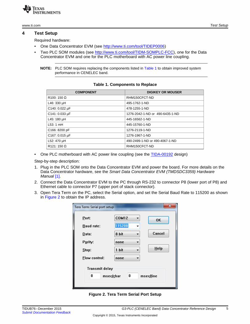
NOTE: PLC SOM requires replacing the components listed in Table 1 to obtain improved systemperformance in CENELEC band.
Table 1. Components to Replace
COMPONENT DIGIKEY OR MOUSERR100: 150 Ω RHM150CFCT-NDL46: 330 µH 495-1762-1-NDC140: 0.022 µF 478-1255-1-NDC141: 0.033 µF 1276-2042-1-ND or 490-6435-1-NDL45: 180 µH 445-16562-1-NDL53: 1 mH 445-15760-1-NDC166: 8200 pF 1276-2119-1-NDC167: 0.015 µF 1276-1967-1-NDL52: 470 µH 490-2499-1-ND or 490-4067-1-NDR121: 150 Ω RHM150CFCT-ND
• One PLC motherboard with AC power line coupling (see the TIDA-00192 design)
Step-by-step description:1. Plug in the PLC SOM onto the Data Concentrator EVM and power the board. For more details on the
Data Concentrator hardware, see the Smart Data Concentrator EVM (TMDSDC3359) HardwareManual [1].
2. Connect the Data Concentrator EVM to the PC through RS-232 to connector P8 (lower port of P8) andEthernet cable to connector P7 (upper port of stack connector).
3. Open Tera Term on the PC, select the Serial option, and set the Serial Baud Rate to 115200 as shownin Figure 2 to obtain the IP address.
Figure 2. Tera Term Serial Port Setup
5TIDUB76–December 2015 G3-PLC (CENELEC Band) Data Concentrator Reference DesignSubmit Documentation Feedback
Copyright © 2015, Texas Instruments Incorporated
Test Setup www.ti.com
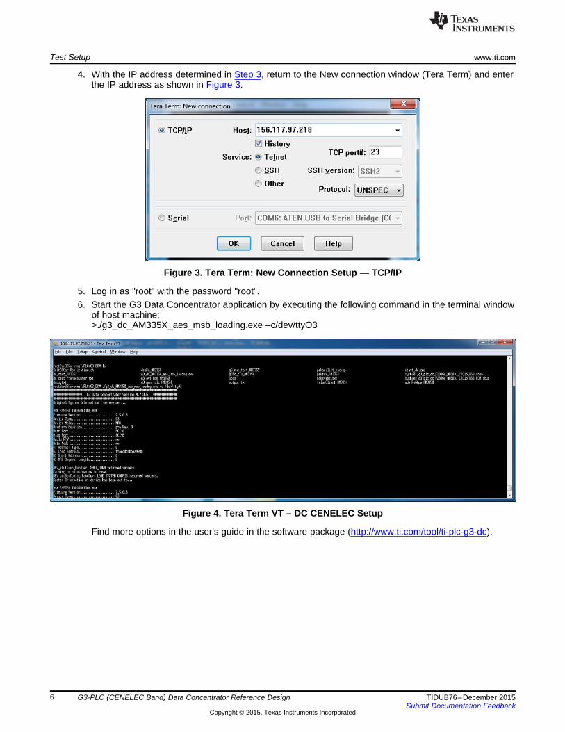
4. With the IP address determined in Step 3, return to the New connection window (Tera Term) and enterthe IP address as shown in Figure 3.
Figure 3. Tera Term: New Connection Setup — TCP/IP
5. Log in as "root" with the password "root".6. Start the G3 Data Concentrator application by executing the following command in the terminal window
of host machine:>./g3_dc_AM335X_aes_msb_loading.exe –c/dev/ttyO3
Figure 4. Tera Term VT – DC CENELEC Setup
Find more options in the user's guide in the software package (http://www.ti.com/tool/ti-plc-g3-dc).
6 G3-PLC (CENELEC Band) Data Concentrator Reference Design TIDUB76–December 2015Submit Documentation Feedback
Copyright © 2015, Texas Instruments Incorporated
www.ti.com Test Setup
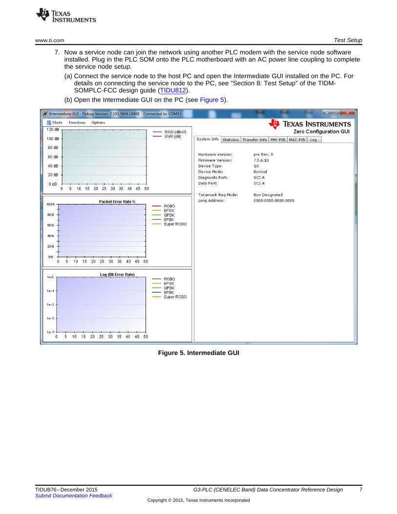
7. Now a service node can join the network using another PLC modem with the service node softwareinstalled. Plug in the PLC SOM onto the PLC motherboard with an AC power line coupling to completethe service node setup.(a) Connect the service node to the host PC and open the Intermediate GUI installed on the PC. For
details on connecting the service node to the PC, see "Section 8: Test Setup" of the TIDM-SOMPLC-FCC design guide (TIDU812).
(b) Open the Intermediate GUI on the PC (see Figure 5).
Figure 5. Intermediate GUI
7TIDUB76–December 2015 G3-PLC (CENELEC Band) Data Concentrator Reference DesignSubmit Documentation Feedback
Copyright © 2015, Texas Instruments Incorporated

Test Setup www.ti.com
(c) Select Options → PHY Parameters and ensure CENELEC band is selected.
Figure 6. G3 PHY Parameters Configuration
8 G3-PLC (CENELEC Band) Data Concentrator Reference Design TIDUB76–December 2015Submit Documentation Feedback
Copyright © 2015, Texas Instruments Incorporated
www.ti.com Test Setup
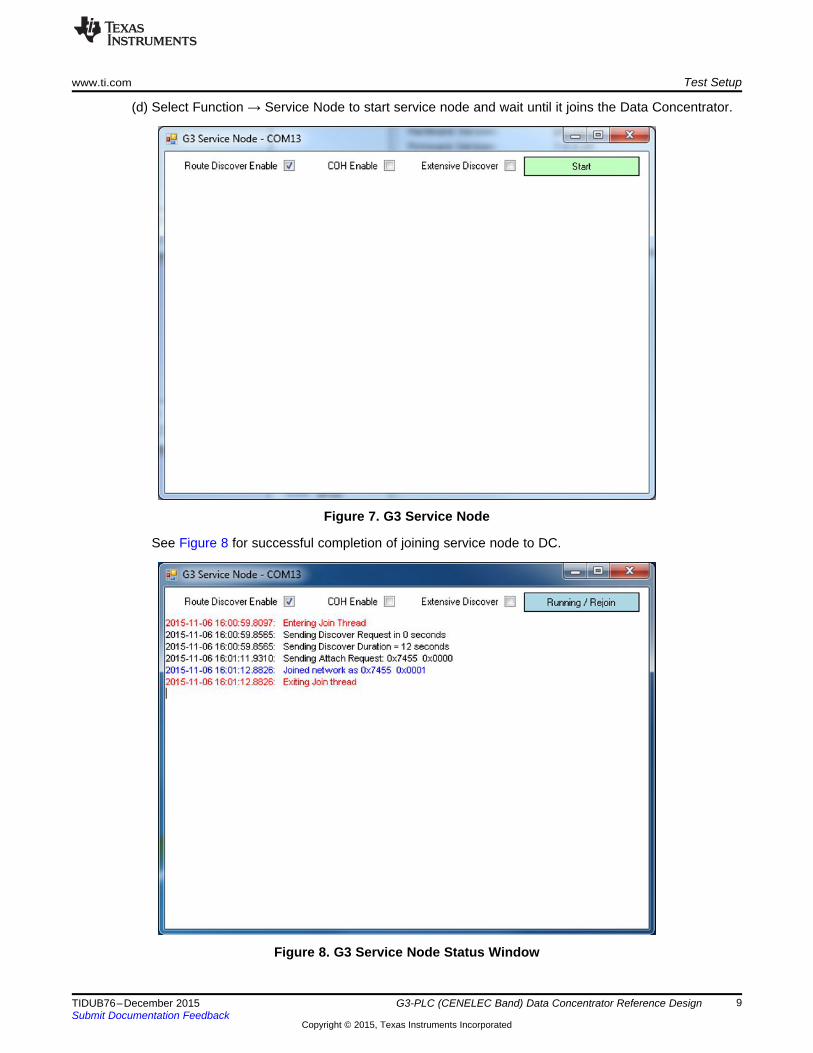
(d) Select Function → Service Node to start service node and wait until it joins the Data Concentrator.
Figure 7. G3 Service Node
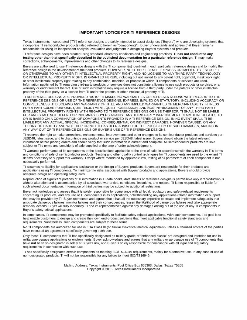
See Figure 8 for successful completion of joining service node to DC.
Figure 8. G3 Service Node Status Window
9TIDUB76–December 2015 G3-PLC (CENELEC Band) Data Concentrator Reference DesignSubmit Documentation Feedback
Copyright © 2015, Texas Instruments Incorporated

Test Data www.ti.com
8. To transfer data: Once the service node has joined, trigger a simple data transfer by using theapplication "udpIPv6App_AM335X > ./udpIPv6App_AM335x –l 100 –s 0x1". The packet length is 100and short address is 0x1.
Find more options in the user’s guide in the software package (http://www.ti.com/tool/ti-plc-g3-dc).
5 Test DataOnce the service node has joined over the network, the user can trigger a simple data transfer over thenetwork by using the application "udpIPv6App_AM335X > ./udpIPv6App_AM335x –l 100 –s 0x1".
With data transfer initiated, the round trip time to send data from the Data Concentrator to the servicenode is displayed in milliseconds as shown in Figure 9.
Figure 9. Test Data
10 G3-PLC (CENELEC Band) Data Concentrator Reference Design TIDUB76–December 2015Submit Documentation Feedback
Copyright © 2015, Texas Instruments Incorporated

www.ti.com Design Files
6 Design Files
6.1 SchematicsTo download the schematics. see the design files at TIDEP0059.
6.2 Bill of MaterialsTo download the bill of materials (BOM), see the design files at TIDEP0059.
6.3 Layout PrintsTo download the layout prints, see the design files at TIDEP0059.
6.4 Gerber FilesTo download the Gerber files, see the design files at TIDEP0059.
6.5 Assembly DrawingsTo download the assembly drawings, see the design files at TIDEP0059.
7 Software FilesTo download the software files, see the design files at TIDEP0059.
8 References
1. Texas Instruments, Smart Data Concentrator EVM (TMDSDC3359) Hardware Manual,TMDSDC3359 Wiki(http://processors.wiki.ti.com/index.php/Smart_Data_Concentrator_EVM_(TMDSDC3359)_Hardware_Manual)
9 About the AuthorNAVEEN KALA is a system applications engineer at Texas Instruments, where he is responsible forproviding technical support and training on Smart Grid solutions and driving solutions for SmartGrid/Metering, and working on defining future requirements in roadmap. He received the M.Eng. degree inelectrical and computer engineering from the University of Iowa.
11TIDUB76–December 2015 G3-PLC (CENELEC Band) Data Concentrator Reference DesignSubmit Documentation Feedback
Copyright © 2015, Texas Instruments Incorporated
IMPORTANT NOTICE FOR TI REFERENCE DESIGNS
Texas Instruments Incorporated ("TI") reference designs are solely intended to assist designers (“Buyers”) who are developing systems thatincorporate TI semiconductor products (also referred to herein as “components”). Buyer understands and agrees that Buyer remainsresponsible for using its independent analysis, evaluation and judgment in designing Buyer’s systems and products.TI reference designs have been created using standard laboratory conditions and engineering practices. TI has not conducted anytesting other than that specifically described in the published documentation for a particular reference design. TI may makecorrections, enhancements, improvements and other changes to its reference designs.Buyers are authorized to use TI reference designs with the TI component(s) identified in each particular reference design and to modify thereference design in the development of their end products. HOWEVER, NO OTHER LICENSE, EXPRESS OR IMPLIED, BY ESTOPPELOR OTHERWISE TO ANY OTHER TI INTELLECTUAL PROPERTY RIGHT, AND NO LICENSE TO ANY THIRD PARTY TECHNOLOGYOR INTELLECTUAL PROPERTY RIGHT, IS GRANTED HEREIN, including but not limited to any patent right, copyright, mask work right,or other intellectual property right relating to any combination, machine, or process in which TI components or services are used.Information published by TI regarding third-party products or services does not constitute a license to use such products or services, or awarranty or endorsement thereof. Use of such information may require a license from a third party under the patents or other intellectualproperty of the third party, or a license from TI under the patents or other intellectual property of TI.TI REFERENCE DESIGNS ARE PROVIDED "AS IS". TI MAKES NO WARRANTIES OR REPRESENTATIONS WITH REGARD TO THEREFERENCE DESIGNS OR USE OF THE REFERENCE DESIGNS, EXPRESS, IMPLIED OR STATUTORY, INCLUDING ACCURACY ORCOMPLETENESS. TI DISCLAIMS ANY WARRANTY OF TITLE AND ANY IMPLIED WARRANTIES OF MERCHANTABILITY, FITNESSFOR A PARTICULAR PURPOSE, QUIET ENJOYMENT, QUIET POSSESSION, AND NON-INFRINGEMENT OF ANY THIRD PARTYINTELLECTUAL PROPERTY RIGHTS WITH REGARD TO TI REFERENCE DESIGNS OR USE THEREOF. TI SHALL NOT BE LIABLEFOR AND SHALL NOT DEFEND OR INDEMNIFY BUYERS AGAINST ANY THIRD PARTY INFRINGEMENT CLAIM THAT RELATES TOOR IS BASED ON A COMBINATION OF COMPONENTS PROVIDED IN A TI REFERENCE DESIGN. IN NO EVENT SHALL TI BELIABLE FOR ANY ACTUAL, SPECIAL, INCIDENTAL, CONSEQUENTIAL OR INDIRECT DAMAGES, HOWEVER CAUSED, ON ANYTHEORY OF LIABILITY AND WHETHER OR NOT TI HAS BEEN ADVISED OF THE POSSIBILITY OF SUCH DAMAGES, ARISING INANY WAY OUT OF TI REFERENCE DESIGNS OR BUYER’S USE OF TI REFERENCE DESIGNS.TI reserves the right to make corrections, enhancements, improvements and other changes to its semiconductor products and services perJESD46, latest issue, and to discontinue any product or service per JESD48, latest issue. Buyers should obtain the latest relevantinformation before placing orders and should verify that such information is current and complete. All semiconductor products are soldsubject to TI’s terms and conditions of sale supplied at the time of order acknowledgment.TI warrants performance of its components to the specifications applicable at the time of sale, in accordance with the warranty in TI’s termsand conditions of sale of semiconductor products. Testing and other quality control techniques for TI components are used to the extent TIdeems necessary to support this warranty. Except where mandated by applicable law, testing of all parameters of each component is notnecessarily performed.TI assumes no liability for applications assistance or the design of Buyers’ products. Buyers are responsible for their products andapplications using TI components. To minimize the risks associated with Buyers’ products and applications, Buyers should provideadequate design and operating safeguards.Reproduction of significant portions of TI information in TI data books, data sheets or reference designs is permissible only if reproduction iswithout alteration and is accompanied by all associated warranties, conditions, limitations, and notices. TI is not responsible or liable forsuch altered documentation. Information of third parties may be subject to additional restrictions.Buyer acknowledges and agrees that it is solely responsible for compliance with all legal, regulatory and safety-related requirementsconcerning its products, and any use of TI components in its applications, notwithstanding any applications-related information or supportthat may be provided by TI. Buyer represents and agrees that it has all the necessary expertise to create and implement safeguards thatanticipate dangerous failures, monitor failures and their consequences, lessen the likelihood of dangerous failures and take appropriateremedial actions. Buyer will fully indemnify TI and its representatives against any damages arising out of the use of any TI components inBuyer’s safety-critical applications.In some cases, TI components may be promoted specifically to facilitate safety-related applications. With such components, TI’s goal is tohelp enable customers to design and create their own end-product solutions that meet applicable functional safety standards andrequirements. Nonetheless, such components are subject to these terms.No TI components are authorized for use in FDA Class III (or similar life-critical medical equipment) unless authorized officers of the partieshave executed an agreement specifically governing such use.Only those TI components that TI has specifically designated as military grade or “enhanced plastic” are designed and intended for use inmilitary/aerospace applications or environments. Buyer acknowledges and agrees that any military or aerospace use of TI components thathave not been so designated is solely at Buyer's risk, and Buyer is solely responsible for compliance with all legal and regulatoryrequirements in connection with such use.TI has specifically designated certain components as meeting ISO/TS16949 requirements, mainly for automotive use. In any case of use ofnon-designated products, TI will not be responsible for any failure to meet ISO/TS16949.IMPORTANT NOTICE
Mailing Address: Texas Instruments, Post Office Box 655303, Dallas, Texas 75265Copyright © 2015, Texas Instruments Incorporated