G0CWA Mk2 RTL SDR RADIO SEPTEMBER...
15
G0CWA Mk2 RTL SDR RADIO SEPTEMBER 2012 For use with RTL2832U-based DVB-T USB dongle with the Elonics E4000 tuner Hi, welcome to my latest project my improved version of my SDR radio. This is based on my original design but has taken into account problems mentioned to me (with the original design) in particular, some people have had sensitivity issues. This seems to have been due in the main to the relays. I used the two sets of contacts to control one of the building blocks and inter contact set capacitance was killing the signal. I didn’t notice any major problems myself, although I did lose a bit of signal due to this effect. The problem has been overcome by using separate relays for the input and output signals on all the modules. Internal version
Transcript of G0CWA Mk2 RTL SDR RADIO SEPTEMBER...
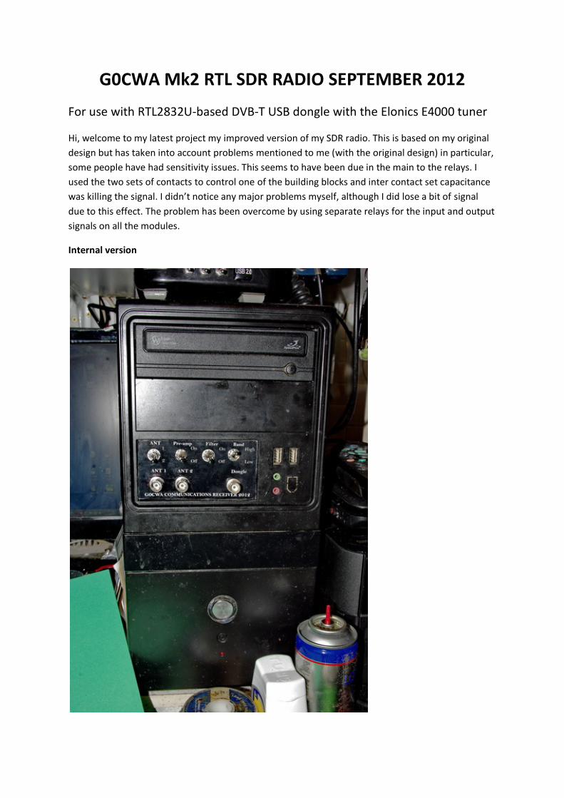
G0CWA Mk2 RTL SDR RADIO SEPTEMBER 2012
For use with RTL2832U-based DVB-T USB dongle with the Elonics E4000 tuner
Hi, welcome to my latest project my improved version of my SDR radio. This is based on my original design but has taken into account problems mentioned to me (with the original design) in particular, some people have had sensitivity issues. This seems to have been due in the main to the relays. I used the two sets of contacts to control one of the building blocks and inter contact set capacitance was killing the signal. I didn’t notice any major problems myself, although I did lose a bit of signal due to this effect. The problem has been overcome by using separate relays for the input and output signals on all the modules.
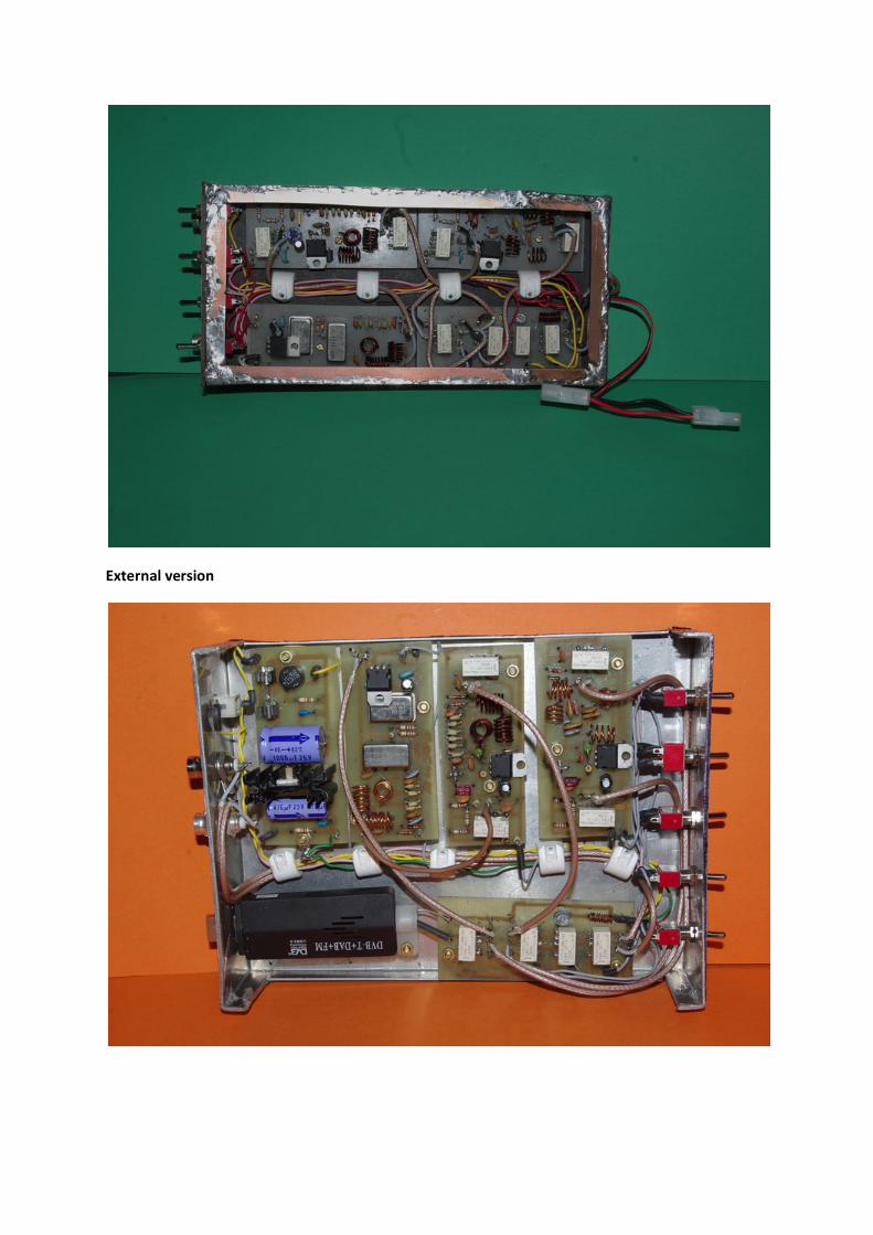
Internal version
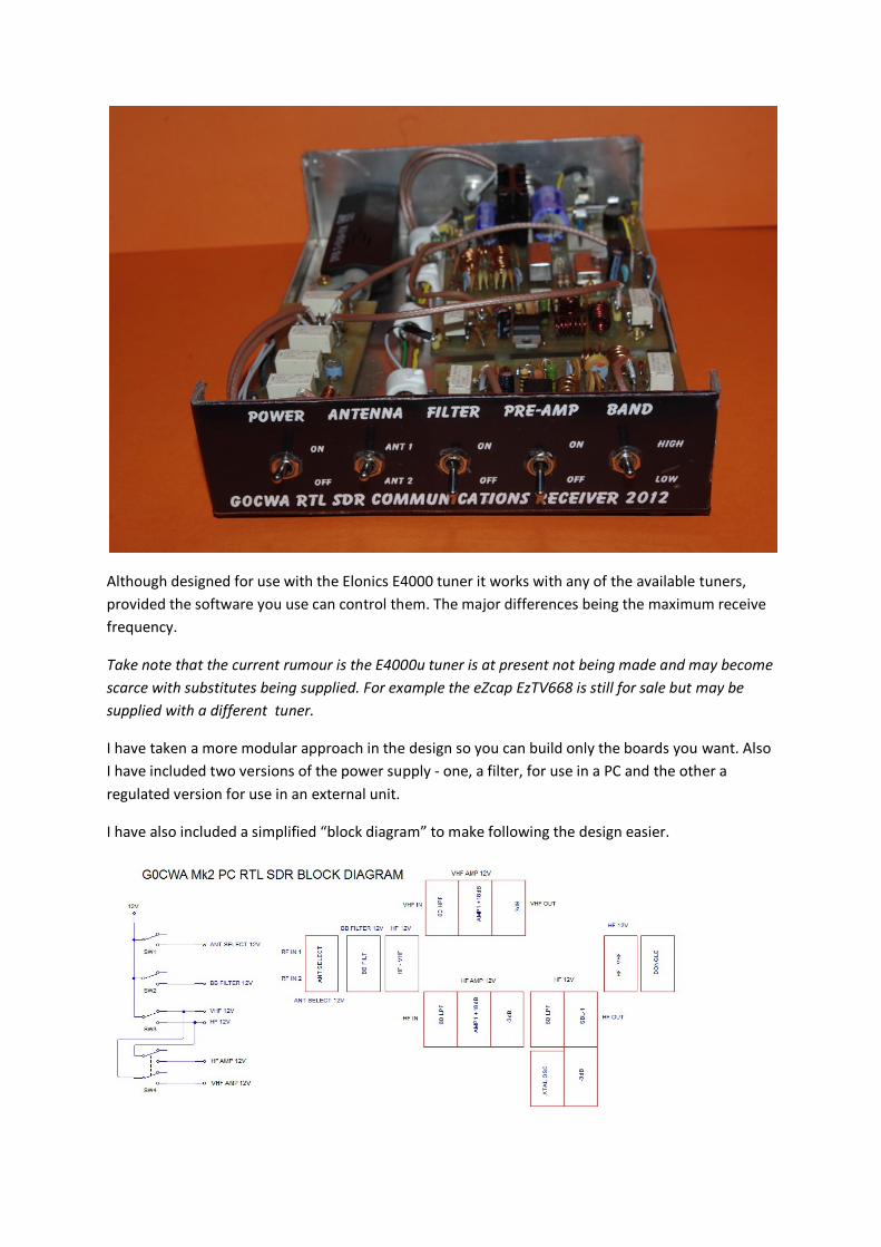
External version
Although designed for use with the Elonics E4000 tuner it works with any of the available tuners, provided the software you use can control them. The major differences being the maximum receive frequency.
Take note that the current rumour is the E4000u tuner is at present not being made and may become scarce with substitutes being supplied. For example the eZcap EzTV668 is still for sale but may be supplied with a different tuner.
I have taken a more modular approach in the design so you can build only the boards you want. Also I have included two versions of the power supply - one, a filter, for use in a PC and the other a regulated version for use in an external unit.
I have also included a simplified “block diagram” to make following the design easier.
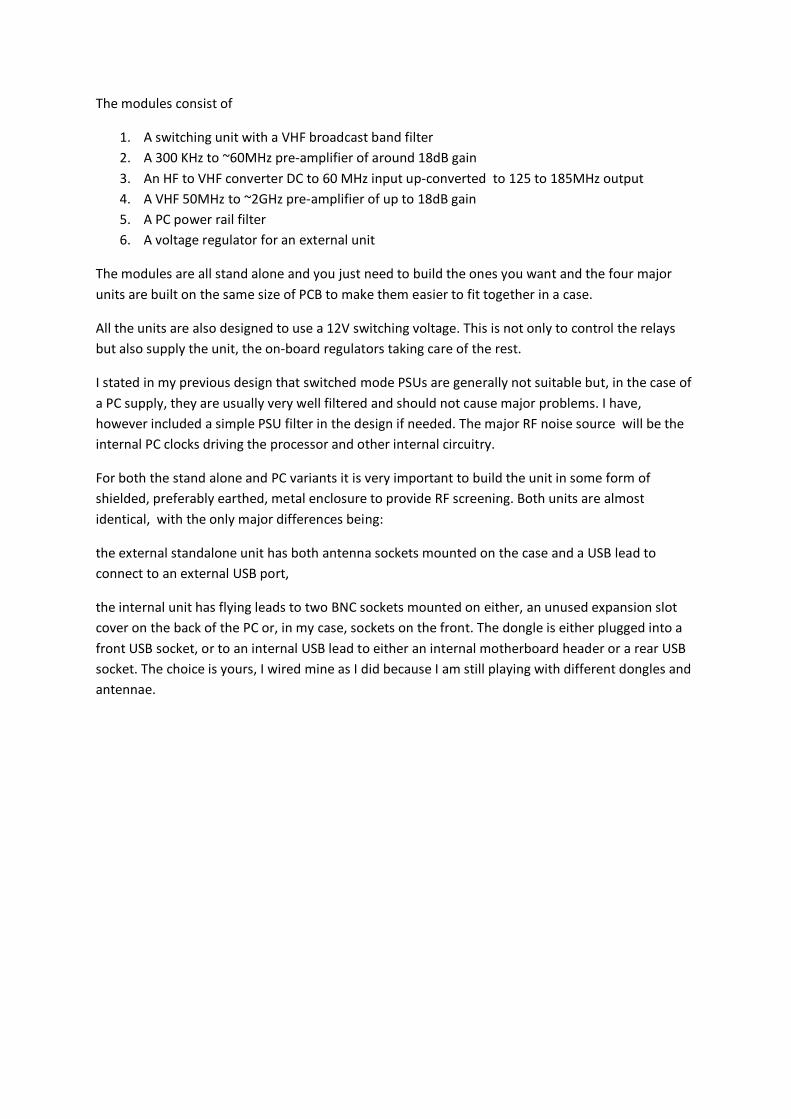
The modules consist of
1. A switching unit with a VHF broadcast band filter 2. A 300 KHz to ~60MHz pre-amplifier of around 18dB gain 3. An HF to VHF converter DC to 60 MHz input up-converted to 125 to 185MHz output 4. A VHF 50MHz to ~2GHz pre-amplifier of up to 18dB gain 5. A PC power rail filter 6. A voltage regulator for an external unit
The modules are all stand alone and you just need to build the ones you want and the four major units are built on the same size of PCB to make them easier to fit together in a case.
All the units are also designed to use a 12V switching voltage. This is not only to control the relays but also supply the unit, the on-board regulators taking care of the rest.
I stated in my previous design that switched mode PSUs are generally not suitable but, in the case of a PC supply, they are usually very well filtered and should not cause major problems. I have, however included a simple PSU filter in the design if needed. The major RF noise source will be the internal PC clocks driving the processor and other internal circuitry.
For both the stand alone and PC variants it is very important to build the unit in some form of shielded, preferably earthed, metal enclosure to provide RF screening. Both units are almost identical, with the only major differences being:
the external standalone unit has both antenna sockets mounted on the case and a USB lead to connect to an external USB port,
the internal unit has flying leads to two BNC sockets mounted on either, an unused expansion slot cover on the back of the PC or, in my case, sockets on the front. The dongle is either plugged into a front USB socket, or to an internal USB lead to either an internal motherboard header or a rear USB socket. The choice is yours, I wired mine as I did because I am still playing with different dongles and antennae.
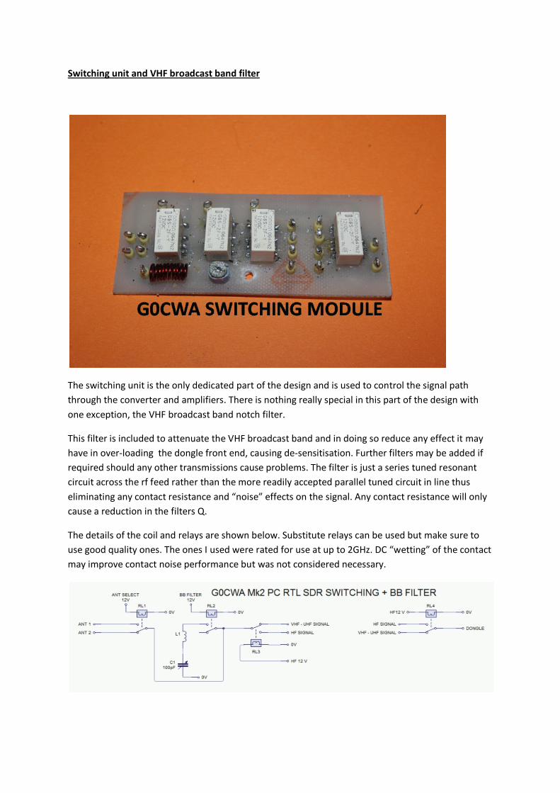
Switching unit and VHF broadcast band filter
The switching unit is the only dedicated part of the design and is used to control the signal path through the converter and amplifiers. There is nothing really special in this part of the design with one exception, the VHF broadcast band notch filter.
This filter is included to attenuate the VHF broadcast band and in doing so reduce any effect it may have in over-loading the dongle front end, causing de-sensitisation. Further filters may be added if required should any other transmissions cause problems. The filter is just a series tuned resonant circuit across the rf feed rather than the more readily accepted parallel tuned circuit in line thus eliminating any contact resistance and “noise” effects on the signal. Any contact resistance will only cause a reduction in the filters Q.
The details of the coil and relays are shown below. Substitute relays can be used but make sure to use good quality ones. The ones I used were rated for use at up to 2GHz. DC “wetting” of the contact may improve contact noise performance but was not considered necessary.
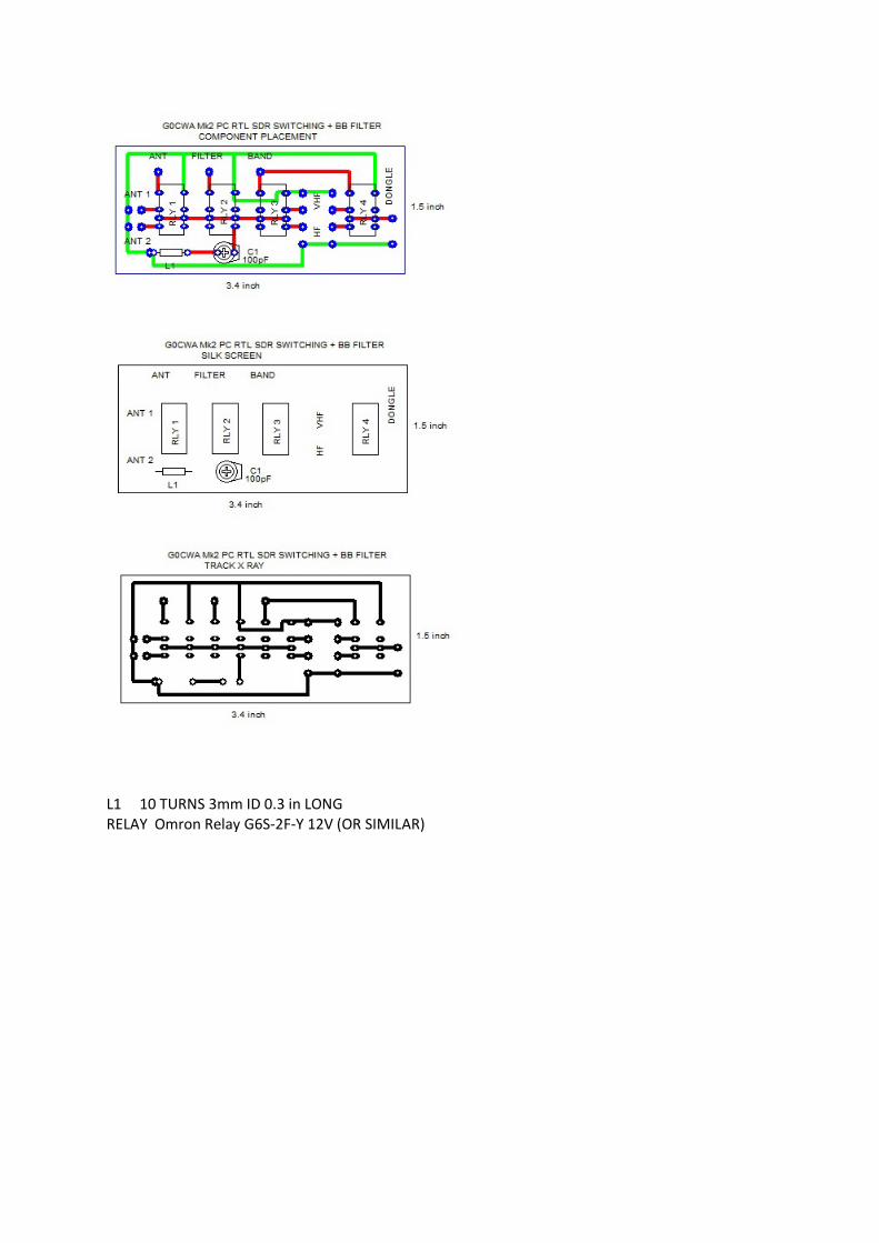
L1 10 TURNS 3mm ID 0.3 in LONG RELAY Omron Relay G6S-2F-Y 12V (OR SIMILAR)
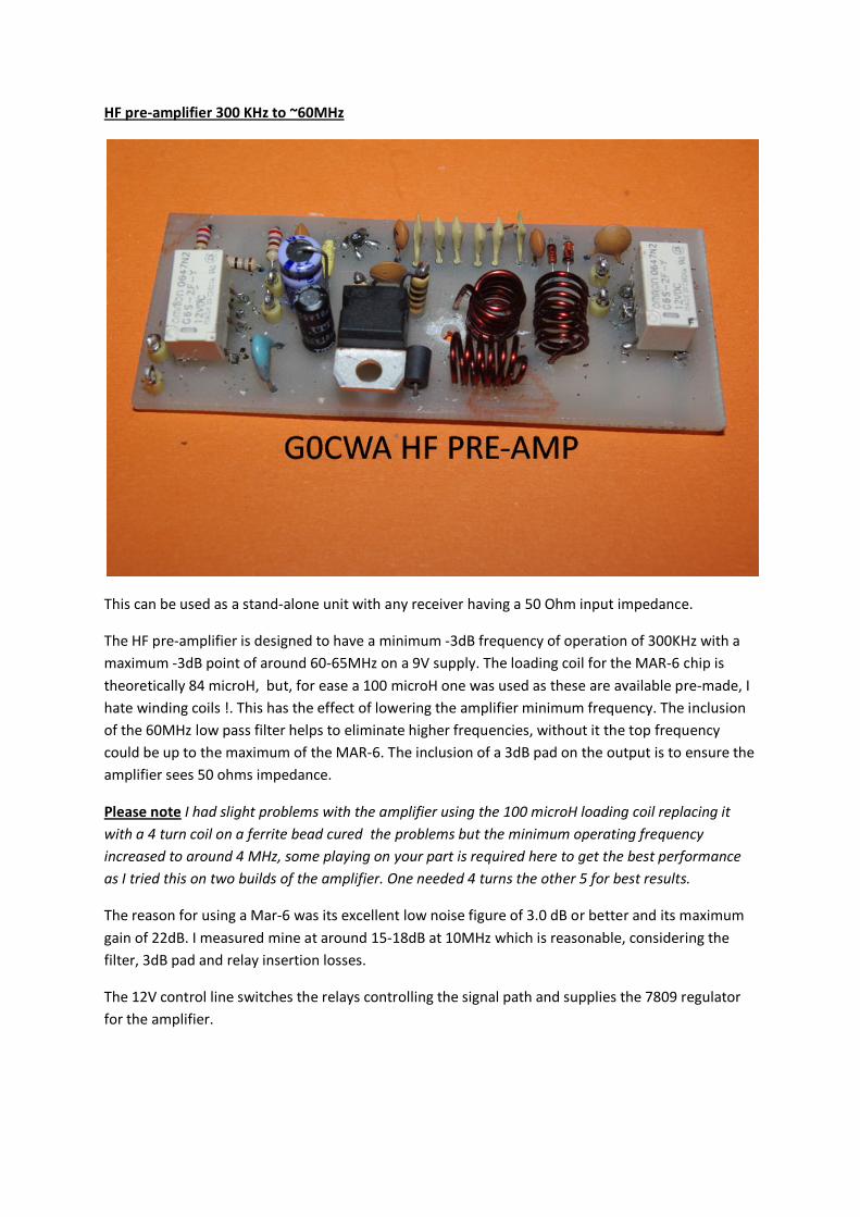
HF pre-amplifier 300 KHz to ~60MHz
This can be used as a stand-alone unit with any receiver having a 50 Ohm input impedance.
The HF pre-amplifier is designed to have a minimum -3dB frequency of operation of 300KHz with a maximum -3dB point of around 60-65MHz on a 9V supply. The loading coil for the MAR-6 chip is theoretically 84 microH, but, for ease a 100 microH one was used as these are available pre-made, I hate winding coils !. This has the effect of lowering the amplifier minimum frequency. The inclusion of the 60MHz low pass filter helps to eliminate higher frequencies, without it the top frequency could be up to the maximum of the MAR-6. The inclusion of a 3dB pad on the output is to ensure the amplifier sees 50 ohms impedance.
Please note I had slight problems with the amplifier using the 100 microH loading coil replacing it with a 4 turn coil on a ferrite bead cured the problems but the minimum operating frequency increased to around 4 MHz, some playing on your part is required here to get the best performance as I tried this on two builds of the amplifier. One needed 4 turns the other 5 for best results.
The reason for using a Mar-6 was its excellent low noise figure of 3.0 dB or better and its maximum gain of 22dB. I measured mine at around 15-18dB at 10MHz which is reasonable, considering the filter, 3dB pad and relay insertion losses.
The 12V control line switches the relays controlling the signal path and supplies the 7809 regulator for the amplifier.
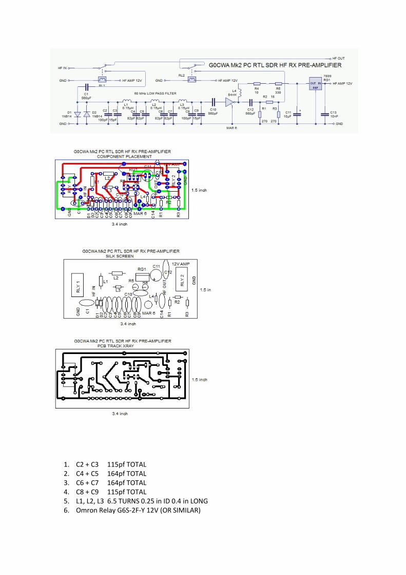
1. C2 + C3 115pf TOTAL 2. C4 + C5 164pf TOTAL 3. C6 + C7 164pf TOTAL 4. C8 + C9 115pf TOTAL 5. L1, L2, L3 6.5 TURNS 0.25 in ID 0.4 in LONG 6. Omron Relay G6S-2F-Y 12V (OR SIMILAR)
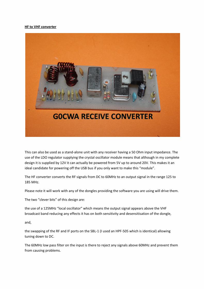
HF to VHF converter
This can also be used as a stand-alone unit with any receiver having a 50 Ohm input impedance. The use of the LDO regulator supplying the crystal oscillator module means that although in my complete design it is supplied by 12V it can actually be powered from 5V up to around 20V. This makes it an ideal candidate for powering off the USB bus if you only want to make this “module”.
The HF converter converts the RF signals from DC to 60MHz to an output signal in the range 125 to 185 MHz.
Please note it will work with any of the dongles providing the software you are using will drive them.
The two “clever bits” of this design are:
the use of a 125MHz “local oscillator” which means the output signal appears above the VHF broadcast band reducing any effects it has on both sensitivity and desensitisation of the dongle,
and,
the swapping of the RF and IF ports on the SBL-1 (I used an HPF-505 which is identical) allowing tuning down to DC.
The 60MHz low pass filter on the input is there to reject any signals above 60MHz and prevent them from causing problems.
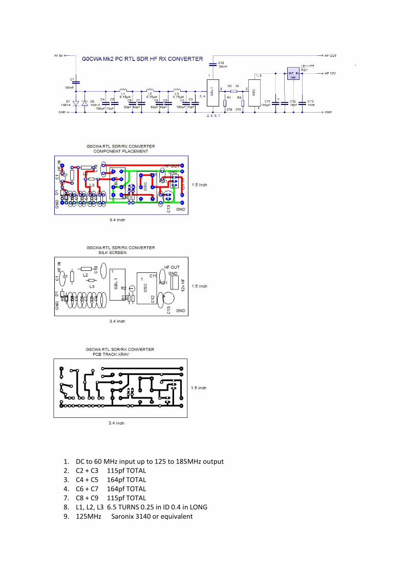
1. DC to 60 MHz input up to 125 to 185MHz output 2. C2 + C3 115pf TOTAL 3. C4 + C5 164pf TOTAL 4. C6 + C7 164pf TOTAL 7. C8 + C9 115pf TOTAL 8. L1, L2, L3 6.5 TURNS 0.25 in ID 0.4 in LONG 9. 125MHz Saronix 3140 or equivalent
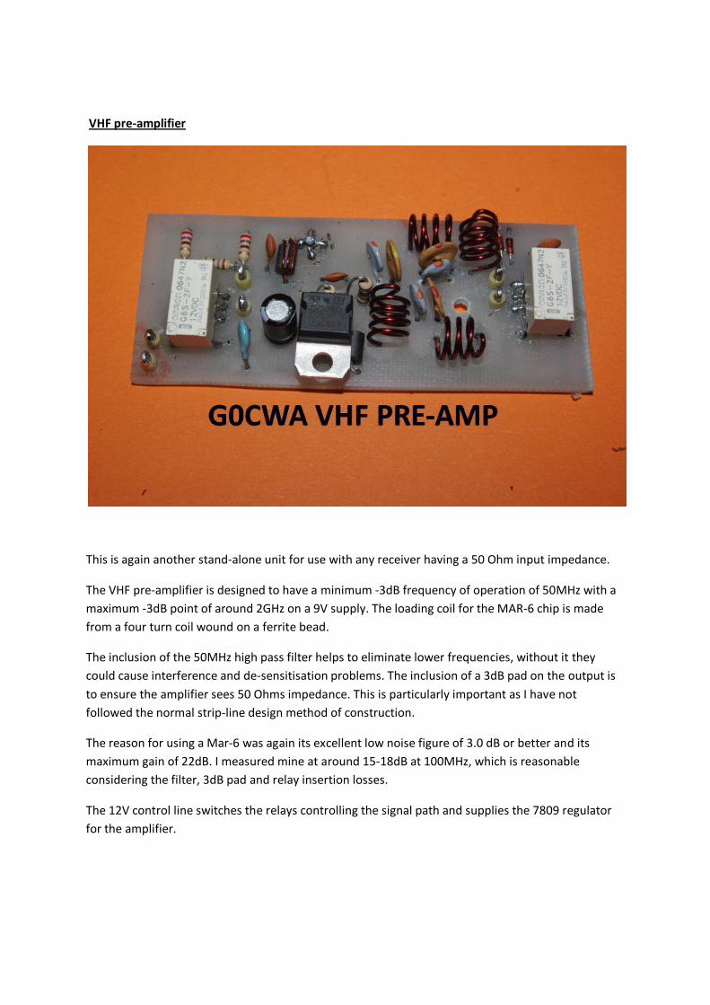
VHF pre-amplifier
This is again another stand-alone unit for use with any receiver having a 50 Ohm input impedance.
The VHF pre-amplifier is designed to have a minimum -3dB frequency of operation of 50MHz with a maximum -3dB point of around 2GHz on a 9V supply. The loading coil for the MAR-6 chip is made from a four turn coil wound on a ferrite bead.
The inclusion of the 50MHz high pass filter helps to eliminate lower frequencies, without it they could cause interference and de-sensitisation problems. The inclusion of a 3dB pad on the output is to ensure the amplifier sees 50 Ohms impedance. This is particularly important as I have not followed the normal strip-line design method of construction.
The reason for using a Mar-6 was again its excellent low noise figure of 3.0 dB or better and its maximum gain of 22dB. I measured mine at around 15-18dB at 100MHz, which is reasonable considering the filter, 3dB pad and relay insertion losses.
The 12V control line switches the relays controlling the signal path and supplies the 7809 regulator for the amplifier.
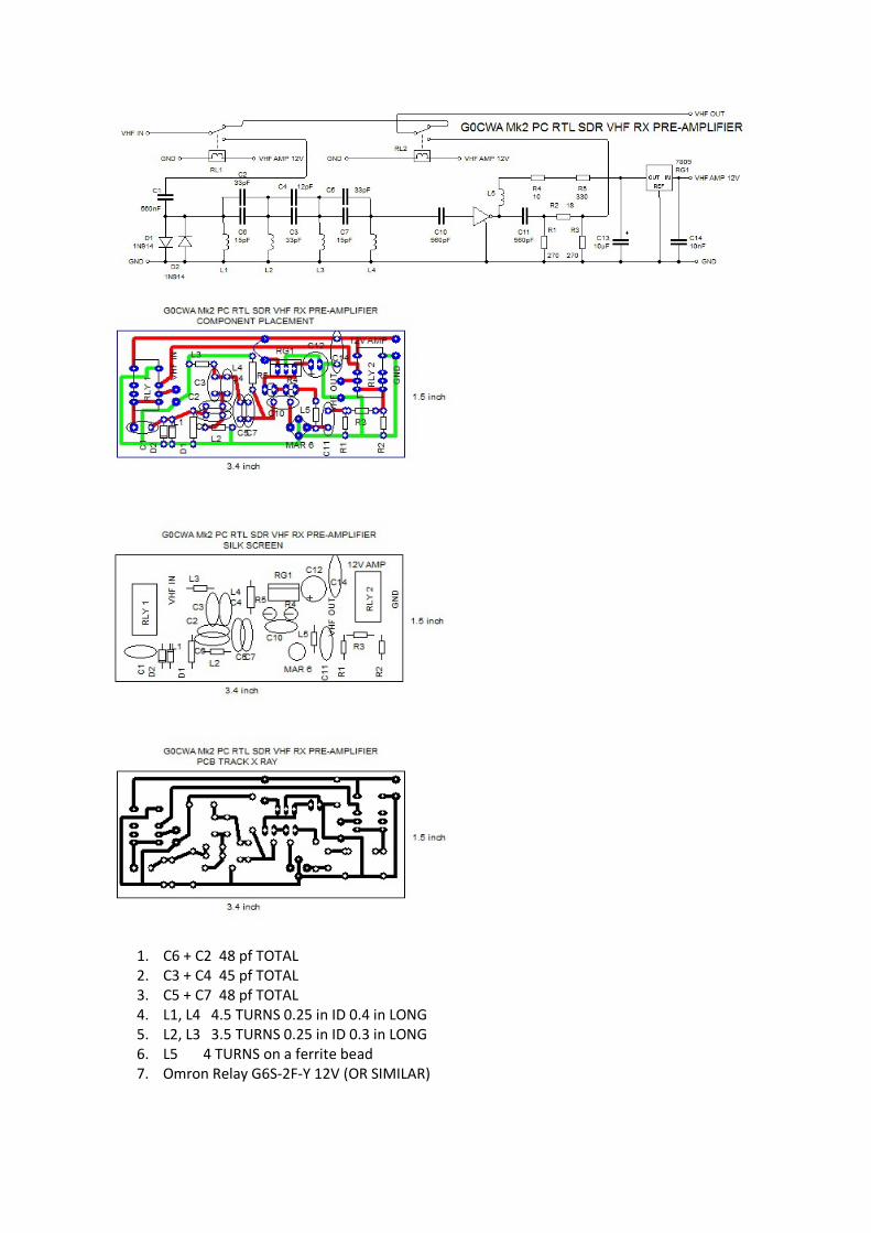
1. C6 + C2 48 pf TOTAL 2. C3 + C4 45 pf TOTAL 3. C5 + C7 48 pf TOTAL 4. L1, L4 4.5 TURNS 0.25 in ID 0.4 in LONG 5. L2, L3 3.5 TURNS 0.25 in ID 0.3 in LONG 6. L5 4 TURNS on a ferrite bead 7. Omron Relay G6S-2F-Y 12V (OR SIMILAR)
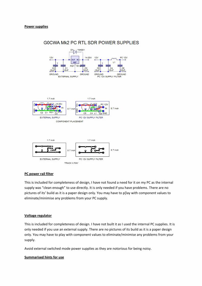
Power supplies
PC power rail filter
This is included for completeness of design, I have not found a need for it on my PC as the internal supply was “clean enough” to use directly. It is only needed if you have problems. There are no pictures of its’ build as it is a paper design only. You may have to p[lay with component values to eliminate/minimise any problems from your PC supply.
Voltage regulator
This is included for completeness of design. I have not built it as I used the internal PC supplies. It is only needed if you use an external supply. There are no pictures of its build as it is a paper design only. You may have to play with component values to eliminate/minimise any problems from your supply.
Avoid external switched mode power supplies as they are notorious for being noisy.
Summarised hints for use
The use of the complete system is relatively straightforward and only the broadest of advice is given as a lot will depend on your antennae and other variables to do with your system.
I found my complete system and dongle gave the most sensitivity with the dongle gain set to manual and at a minimum level when using the pre-amplifiers. Turn the dongle gain up slowly till desensitisation starts to occur then back off the gain a little bit. This is the most sensitive setting. In most cases this is more sensitive than the dongle alone.
If possible turn off the receiver AGC. This again increases the overall sensitivity. From the performance of my dongle the AGC appears to be audio generated but I could be wrong on this point.
Try to use an appropriate antenna on the system with an ATU. This again will give a better signal. I use a long-wire up to around 20MHz and a disk-cone above. This is not ideal as resonant antennas are by far the best particularly as you go up in frequency.
Useful Links
http://hackaday.com/2012/03/20/software-defined-radio-from-a-usb-tv-capture-card/
An article by Brian Benchoff , I first came across this very cheap communications receiver idea on the QRZ forum in a posting by Sue AF6LJ.
http://forums.qrz.com/showthread.php?339016-For-The-SDR-Fans
Please note double check the dongle is compatible. A brief list is at the link below
http://sdr.osmocom.org/trac/wiki/rtl-sdr
The list of software available includes HDSDR, WINRAD and my personal favourite, SDR Sharp
http://sdrsharp.com/
The site takes a little bit of exploring to find everything but is well worth the effort as at present I have not found any problems and the people running the site and writing the software seem to be very approachable for help and advice. Just make sure you download the latest version.
See my posting on the radio board for further details at:
http://theradioboard.com/rb/viewtopic.php?t=4139
The idea of a receive converter was, I believe, first broached by George (M1GEO) / and Chris (G8OCV) on
http://www.george-smart.co.uk/wiki/FunCube_Upconverter
Mar amplifer design document
http://www.avagotech.com/docs/5967-5924E
Filter design programme

http://www.aade.com/
Any comments will be gratefully received and as usual I can be contacted by e-mail at [email protected] or via the Radio Board and QRZ forums as G0CWA. I cannot guarantee to see your questions if posted elsewhere REMEMBER TO CHECK THE PCB TRACK LAYOUTS AND MIRROR THEM IF NEEDED. I HAVE PRESENTED THEM AS “X-RAY” VIEWS OF THE FINAL BOARD !!!! A SIMPLE WAY TO MOUNT ANY SURFACE MOUNT COMPONENTS ON A SINGLE SIDED PCB IS TO SOLDER A VERO PIN THROUGH THE BOARD. THE PIN HEAD MAKES A SMALL PAD TO SOLDER COMPONENTS TO ON THE COMPONENT SIDE. All the best for now and happy building de G0CWA (Nick) PLEASE NOTE if you downloaded this document from anywhere but http://makearadio.com or http://makearadio.com/visitors/nick-sdr2.php I can not guarantee you will have the latest version, Please inform Dave if it was downloaded from another site. Daves site is the ONLY ONE I HAVE AUTHORISED to distribute/display my projects and documents. However links to the projects are permitted with Daves permission.