G Model ARTICLE IN PRESS - University of California,...
5
Please cite this article in press as: S. Banetta, et al., Manufacturing of small-scale mock-ups and of a semi-prototype of the ITER Normal Heat Flux First Wall, Fusion Eng. Des. (2014), http://dx.doi.org/10.1016/j.fusengdes.2014.04.020 ARTICLE IN PRESS G Model FUSION-7454; No. of Pages 5 Fusion Engineering and Design xxx (2014) xxx–xxx Contents lists available at ScienceDirect Fusion Engineering and Design jo ur nal home p age: www.elsevier.com/locate/fusengdes Manufacturing of small-scale mock-ups and of a semi-prototype of the ITER Normal Heat Flux First Wall S. Banetta a,∗ , F. Zacchia a , P. Lorenzetto a , I. Bobin-Vastra b , B. Boireau b , A. Cottin b , R. Mitteau c , R. Eaton c , R. Raffray c a Fusion for Energy, 2 Carrer Josep Pla, 08019 Barcelona, Spain b AREVA NP, 30 bd de l’Industrie, 71205 Le Creusot, France c ITER Organization, Route de Vinon sur Verdon, 13115 Saint Paul Lez Durance, France a r t i c l e i n f o Article history: Received 13 September 2013 Received in revised form 4 April 2014 Accepted 9 April 2014 Available online xxx Keywords: ITER First Wall Manufacturing Hot Isostatic Pressing a b s t r a c t This paper describes the manufacturing development and fabrication of reduced scale ITER First Wall (FW) mock-ups of the Normal Heat Flux (NHF) design, including a “semi-prototype” with a dimension of 305 mm × 660 mm, corresponding to about 1/6 of a full-scale panel. The activity was carried out in the framework of the pre-qualification of the European Domestic Agency (EU-DA or F4E) for the supply of the European share of the ITER First Wall. The hardware consists of three Upgraded (2 MW/m 2 ) Normal Heat Flux (U-NHF) small-scale mock-ups, bearing 3 beryllium tiles each, and of one Semi-Prototype, representing six full-scale fingers and bearing a total of 84 beryllium tiles. The manufacturing process makes extensive use of Hot Isostatic Pressing, which was developed over more than a decade during ITER Engineering Design Activity phase. The main manufacturing steps for the semi-prototype are described, with special reference to the lessons learned and the implications impacting the future fabrication of the full-scale prototype and the series which consists of 218 panels plus spares. In addition, a “tile-size” mock-up was manufactured in order to assess the performance of larger tiles. The use of larger tiles would be highly beneficial since it would allow a significant reduction of the panel assembly time. © 2014 Elsevier B.V. All rights reserved. 1. Introduction The Blanket modules consist of a water-cooled austenitic 316L(N)-IG Stainless Steel (SS) Shield Block on which a separable First Wall (FW) panel is mechanically attached. The FW panels have typical dimensions of 1 m × 1.5 m. They consist of a bi-metallic sup- port structure made from 15–25 mm thick CuCrZr alloy bonded to a 40–50 mm thick 316L(N) SS backing plate on which are joined 10 mm thick Beryllium tiles, see Fig. 1. The First Wall panel plasma surface is composed of fingers (see Fig. 2), and each of these fin- gers is cooled by pressurized water at 4 MPa, with 100 ◦ C inlet and 140 ◦ C outlet. Depending on the region of the machine where they are pos- itioned, the panels shall be able to sustain 2 different levels of heat flux, namely the Normal Heat Flux (NHF) that can vary up to about 2 MW/m 2 and the Enhanced Heat Flux (EHF) that varies above that ∗ Corresponding author. Tel.: +34 933201162. E-mail address: [email protected] (S. Banetta). value and up to 4.7 MW/m 2 . The FW panels shall also undergo a maximum neutron wall load of 0.8 MW/m 2 . The foreseen life of a FW panel in ITER is of 15,000 cycles. The ITER Organization (IO) and F4E have jointly brought forward the design of these panels, see [1] and [2]. The European Union Domestic Agency for ITER, Fusion for Energy (F4E), has undertaken a program with primary objective to demonstrate its capability to provide FW components of accept- able quality and that these components are capable of successfully passing the formal test program including heat flux tests. To this purpose, a contract has been awarded in 2010 to AREVA NP to manufacture Small Scale Mock-ups (SSMK’s) and semi- prototypes. Overall, three Upgraded (2 MW/m 2 ) Normal Heat Flux (U-NHF) small-scale mock-ups have been completed and two semi- prototypes (SPs) are being manufactured. The FW panels are classified as non-Safety Important Com- ponent (non-SIC) and shall be manufactured as Quality class 1 components, for investment protection reasons. As In-Vessel com- ponents, they shall follow the requirements of the Structural Design Criteria for ITER In-Vessel Components [3]. In order to be qualified, http://dx.doi.org/10.1016/j.fusengdes.2014.04.020 0920-3796/© 2014 Elsevier B.V. All rights reserved.
Transcript of G Model ARTICLE IN PRESS - University of California,...
F
Mt
SRa
b
c
a
ARRAA
KIMH
1
3Ftpa1sg1
ifl2
h0
ARTICLE IN PRESSG ModelUSION-7454; No. of Pages 5
Fusion Engineering and Design xxx (2014) xxx–xxx
Contents lists available at ScienceDirect
Fusion Engineering and Design
jo ur nal home p age: www.elsev ier .com/ locate / fusengdes
anufacturing of small-scale mock-ups and of a semi-prototype ofhe ITER Normal Heat Flux First Wall
. Banettaa,∗, F. Zacchiaa, P. Lorenzettoa, I. Bobin-Vastrab, B. Boireaub, A. Cottinb,. Mitteauc, R. Eatonc, R. Raffrayc
Fusion for Energy, 2 Carrer Josep Pla, 08019 Barcelona, SpainAREVA NP, 30 bd de l’Industrie, 71205 Le Creusot, FranceITER Organization, Route de Vinon sur Verdon, 13115 Saint Paul Lez Durance, France
r t i c l e i n f o
rticle history:eceived 13 September 2013eceived in revised form 4 April 2014ccepted 9 April 2014vailable online xxx
eywords:TER First Wall
anufacturingot Isostatic Pressing
a b s t r a c t
This paper describes the manufacturing development and fabrication of reduced scale ITER First Wall(FW) mock-ups of the Normal Heat Flux (NHF) design, including a “semi-prototype” with a dimension of305 mm × 660 mm, corresponding to about 1/6 of a full-scale panel. The activity was carried out in theframework of the pre-qualification of the European Domestic Agency (EU-DA or F4E) for the supply ofthe European share of the ITER First Wall. The hardware consists of three Upgraded (2 MW/m2) NormalHeat Flux (U-NHF) small-scale mock-ups, bearing 3 beryllium tiles each, and of one Semi-Prototype,representing six full-scale fingers and bearing a total of 84 beryllium tiles.
The manufacturing process makes extensive use of Hot Isostatic Pressing, which was developed overmore than a decade during ITER Engineering Design Activity phase. The main manufacturing steps forthe semi-prototype are described, with special reference to the lessons learned and the implications
impacting the future fabrication of the full-scale prototype and the series which consists of 218 panelsplus spares.In addition, a “tile-size” mock-up was manufactured in order to assess the performance of larger tiles.The use of larger tiles would be highly beneficial since it would allow a significant reduction of the panelassembly time.
© 2014 Elsevier B.V. All rights reserved.
. Introduction
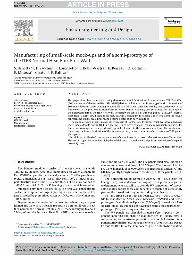
The Blanket modules consist of a water-cooled austenitic16L(N)-IG Stainless Steel (SS) Shield Block on which a separableirst Wall (FW) panel is mechanically attached. The FW panels haveypical dimensions of 1 m × 1.5 m. They consist of a bi-metallic sup-ort structure made from 15–25 mm thick CuCrZr alloy bonded to
40–50 mm thick 316L(N) SS backing plate on which are joined0 mm thick Beryllium tiles, see Fig. 1. The First Wall panel plasmaurface is composed of fingers (see Fig. 2), and each of these fin-ers is cooled by pressurized water at 4 MPa, with 100 ◦C inlet and40 ◦C outlet.
Depending on the region of the machine where they are pos-
Please cite this article in press as: S. Banetta, et al., Manufacturing of sHeat Flux First Wall, Fusion Eng. Des. (2014), http://dx.doi.org/10.101
tioned, the panels shall be able to sustain 2 different levels of heatux, namely the Normal Heat Flux (NHF) that can vary up to about
MW/m2 and the Enhanced Heat Flux (EHF) that varies above that
∗ Corresponding author. Tel.: +34 933201162.E-mail address: [email protected] (S. Banetta).
ttp://dx.doi.org/10.1016/j.fusengdes.2014.04.020920-3796/© 2014 Elsevier B.V. All rights reserved.
value and up to 4.7 MW/m2. The FW panels shall also undergo amaximum neutron wall load of 0.8 MW/m2. The foreseen life of aFW panel in ITER is of 15,000 cycles. The ITER Organization (IO) andF4E have jointly brought forward the design of these panels, see [1]and [2].
The European Union Domestic Agency for ITER, Fusion forEnergy (F4E), has undertaken a program with primary objectiveto demonstrate its capability to provide FW components of accept-able quality and that these components are capable of successfullypassing the formal test program including heat flux tests.
To this purpose, a contract has been awarded in 2010 to AREVANP to manufacture Small Scale Mock-ups (SSMK’s) and semi-prototypes. Overall, three Upgraded (2 MW/m2) Normal Heat Flux(U-NHF) small-scale mock-ups have been completed and two semi-prototypes (SPs) are being manufactured.
The FW panels are classified as non-Safety Important Com-
mall-scale mock-ups and of a semi-prototype of the ITER Normal6/j.fusengdes.2014.04.020
ponent (non-SIC) and shall be manufactured as Quality class 1components, for investment protection reasons. As In-Vessel com-ponents, they shall follow the requirements of the Structural DesignCriteria for ITER In-Vessel Components [3]. In order to be qualified,
ARTICLE IN PRESSG ModelFUSION-7454; No. of Pages 5
2 S. Banetta et al. / Fusion Engineering and Design xxx (2014) xxx–xxx
tpu
2
2
pimt
f
o
••••
2
dssuietuwt
Fig. 1. Rear view of an NHF FW panel.
hese components shall also undergo a High Heat Flux test cam-aign (outside the scope of this paper) to test their performancender thermal fatigue.
. Manufacturing development
.1. Design Development Mock-Up (DDMU)
Several manufacturing steps of the established fabrication routeresented new challenges, due to the increase of scale when mov-
ng from the SSMK’s to the SP. For this reason, it was decided toanufacture a dedicated mock-up featuring the main aspects of
he SPs.The DDMU is composed of two fingers corresponding to 2 dif-
erent designs, for 1 and 2 MW/m2 respectively.The critical steps specifically tested during the manufacturing
f the DDMU are the following:
overall shaping of the SS and CuCrZr parts,bending of the stainless steel and CuCrZr body of the fingers,design and manufacturing of the water boxes,assembly in preparation for the Hot Isostatic Pressing (HIP) cycles.
.2. Cutting of the fingers
This is the most critical and significant new activity testeduring the manufacturing development phase. The manufacturingequences identified so far foresee the assembly of the FW paneltarting from SS and CuCrZr plates. The fingers are cut after the HIPsed to join the CuC1 foils and the Be tiles to the assembly result-
ng from the previous HIP cycle (SS/CuCrZr). For the sake of costffectiveness the DDMU was not completed with the Be armor, but
Please cite this article in press as: S. Banetta, et al., Manufacturing of sHeat Flux First Wall, Fusion Eng. Des. (2014), http://dx.doi.org/10.101
his had no impact on the representativeness of this specific man-facturing step. The cutting operation was performed in two steps,ith an Electro Discharge Machining (EDM) applied from the tip of
he fingers followed by a mechanical sawing.
Fig. 2. Exploded view of a NHF finger.
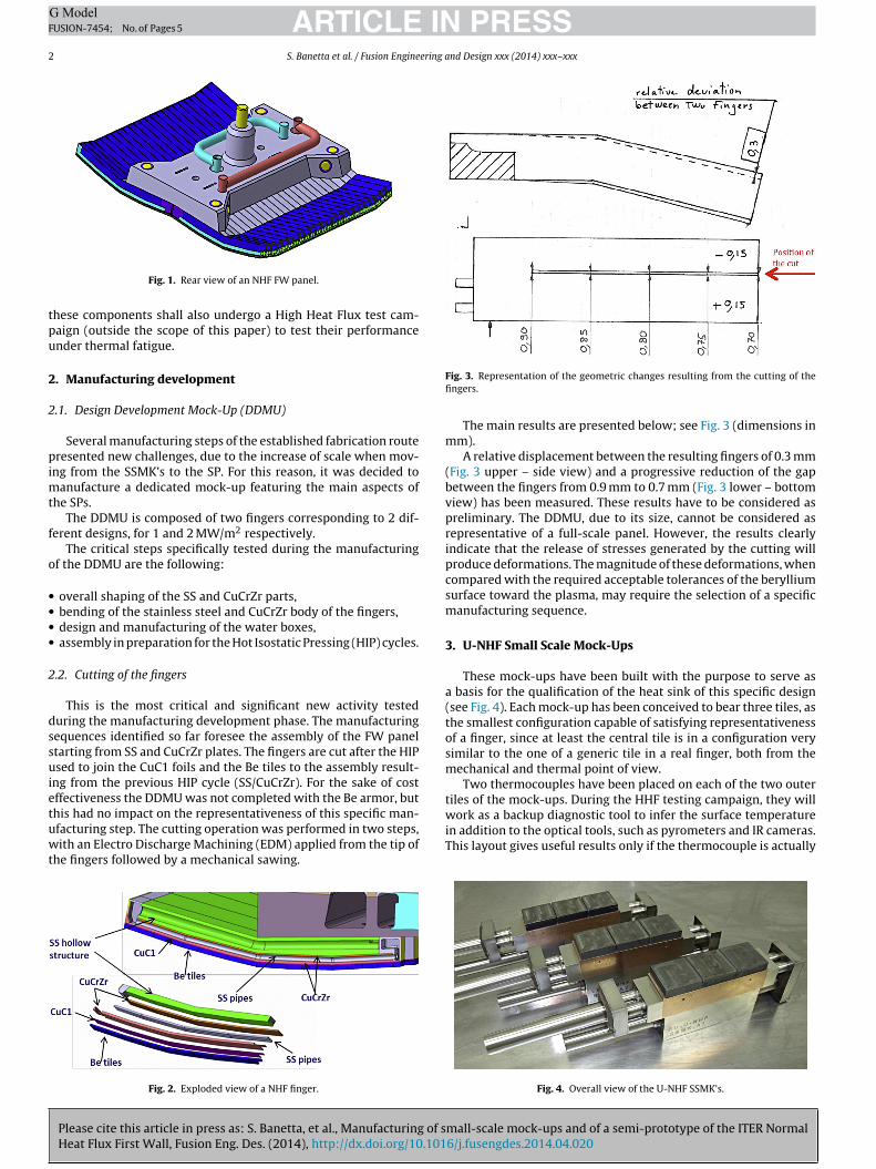
Fig. 3. Representation of the geometric changes resulting from the cutting of thefingers.
The main results are presented below; see Fig. 3 (dimensions inmm).
A relative displacement between the resulting fingers of 0.3 mm(Fig. 3 upper – side view) and a progressive reduction of the gapbetween the fingers from 0.9 mm to 0.7 mm (Fig. 3 lower – bottomview) has been measured. These results have to be considered aspreliminary. The DDMU, due to its size, cannot be considered asrepresentative of a full-scale panel. However, the results clearlyindicate that the release of stresses generated by the cutting willproduce deformations. The magnitude of these deformations, whencompared with the required acceptable tolerances of the berylliumsurface toward the plasma, may require the selection of a specificmanufacturing sequence.
3. U-NHF Small Scale Mock-Ups
These mock-ups have been built with the purpose to serve asa basis for the qualification of the heat sink of this specific design(see Fig. 4). Each mock-up has been conceived to bear three tiles, asthe smallest configuration capable of satisfying representativenessof a finger, since at least the central tile is in a configuration verysimilar to the one of a generic tile in a real finger, both from themechanical and thermal point of view.
Two thermocouples have been placed on each of the two outertiles of the mock-ups. During the HHF testing campaign, they will
mall-scale mock-ups and of a semi-prototype of the ITER Normal6/j.fusengdes.2014.04.020
work as a backup diagnostic tool to infer the surface temperaturein addition to the optical tools, such as pyrometers and IR cameras.This layout gives useful results only if the thermocouple is actually
Fig. 4. Overall view of the U-NHF SSMK’s.

ARTICLE IN PRESSG ModelFUSION-7454; No. of Pages 5
S. Banetta et al. / Fusion Engineering and Design xxx (2014) xxx–xxx 3
pttwF
srt
4
4
bit
nam
•
••
•
•
t
Fig. 7. SS body of the semi-prototype.
evacuation pipe (see Fig. 9). The HIP cycle has been performed at1040 ◦C and 140 MPa, with a hold time of 2 h. The parameters usedduring the HIP cycles are the result of previous R&D activities (somedetails are provided in [4] and [5]). In general, after each HIP cycle,
Fig. 5. Configuration of the thermocouples holes.
laced in contact with the Be tile (i.e. to avoid the uncertainty inhe resistance of contact at the CuCrZr/CuC1/Be interface). Due tohe configuration of the heat sink, it was only possible to drill holeith a 45◦ angle with respect to the surface of the Be, as shown in
ig. 5.These SSMK’s followed exactly the same manufacturing
equence conceived for the semiprototypes and can be consideredepresentative from both the materials properties (mechanical,hermal mainly) and geometrical configuration point of view.
. Semiprototypes
.1. Overview
The semiprototype is composed of 6 full-scale fingers connectedy a SS base serving also as manifold for the distribution of the cool-
ng water, see Fig. 6. It represents the intermediate step betweenhe smaller mock-ups built so far and the full-scale FW panel.
The increase in size implied some new challenges, the most sig-ificant and important of them being the cutting of the fingers,lready described in Section 2.2. Other key new elements of theanufacturing are as follows:
presence of a “faceting” (i.e. the surface of the Be and conse-quently of the CuCrZr is not planar),the length of the fingers now representative of a full-scale panel,the increased complexity of the assembly of the Be tiles (bothfor their overall number 84, and the required precision to becompatible with the cutting of the fingers),the implementation of waterboxes as new concept for the waterflow configurationincreased complexity in the three foreseen assembly operationsin preparation for the HIP cycles.
Please cite this article in press as: S. Banetta, et al., Manufacturing of sHeat Flux First Wall, Fusion Eng. Des. (2014), http://dx.doi.org/10.101
The most interesting manufacturing steps are described in Sec-ions 4.2–4.4.
Fig. 6. Overall view of the semi-prototype (6 fingers).
Fig. 8. Section of the volume filled with SS powder highlighted in yellow. (For inter-pretation of the references to color in this figure legend, the reader is referred to theweb version of the article.)
4.2. Assembly in preparation of SS/SS HIP cycle
The main body of the semiprototype, to be made out of stain-less steel (SS), presents a complex shape (see Fig. 7), the preferredapproach was then to have the various SS parts joined by a prelimi-nary HIP cycle to reduce the machining time and reduce the wastedraw material.
In correspondence of the area shown by the arrow in Fig. 7, andwhich section is shown in Fig. 8, it was needed to couple two rel-atively extended surfaces including a few welded covers, causingthe surface on one side to be not flat enough. The use of SS powder,with a typical dimension of the grains in the range 50–350 �m, atthe interface between the two surfaces to be HIPed, precluded thepresence of void volumes between the two surfaces to be coupled.
A canister was prepared in advance and welded to the body ofthe semiprototype with some spacers to leave open the volumeto be filled with the powder. The powder was inserted througha dedicated slot and then closed with a welded cover bearing an
mall-scale mock-ups and of a semi-prototype of the ITER Normal6/j.fusengdes.2014.04.020
Fig. 9. Filling of the gap with SS powder.
ARTICLE IN PRESSG ModelFUSION-7454; No. of Pages 5
4 S. Banetta et al. / Fusion Engineering and Design xxx (2014) xxx–xxx
tw
4
iacipbpemw
tcdacaviu
4
j
F
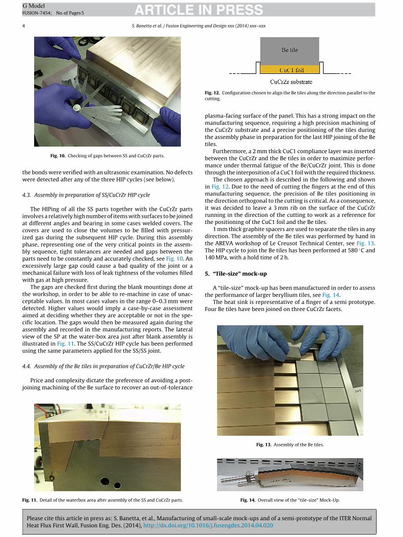
the performance of larger beryllium tiles, see Fig. 14.The heat sink is representative of a finger of a semi prototype.
Four Be tiles have been joined on three CuCrZr facets.
Fig. 10. Checking of gaps between SS and CuCrZr parts.
he bonds were verified with an ultrasonic examination. No defectsere detected after any of the three HIP cycles (see below).
.3. Assembly in preparation of SS/CuCrZr HIP cycle
The HIPing of all the SS parts together with the CuCrZr partsnvolves a relatively high number of items with surfaces to be joinedt different angles and bearing in some cases welded covers. Theovers are used to close the volumes to be filled with pressur-zed gas during the subsequent HIP cycle. During this assemblyhase, representing one of the very critical points in the assem-ly sequence, tight tolerances are needed and gaps between thearts need to be constantly and accurately checked, see Fig. 10. Anxcessively large gap could cause a bad quality of the joint or aechanical failure with loss of leak tightness of the volumes filledith gas at high pressure.
The gaps are checked first during the blank mountings done athe workshop, in order to be able to re-machine in case of unac-eptable values. In most cases values in the range 0–0.3 mm wereetected. Higher values would imply a case-by-case assessmentimed at deciding whether they are acceptable or not in the spe-ific location. The gaps would then be measured again during thessembly and recorded in the manufacturing reports. The lateraliew of the SP at the water-box area just after blank assembly isllustrated in Fig. 11. The SS/CuCrZr HIP cycle has been performedsing the same parameters applied for the SS/SS joint.
.4. Assembly of the Be tiles in preparation of CuCrZr/Be HIP cycle
Please cite this article in press as: S. Banetta, et al., Manufacturing of sHeat Flux First Wall, Fusion Eng. Des. (2014), http://dx.doi.org/10.101
Price and complexity dictate the preference of avoiding a post-oining machining of the Be surface to recover an out-of-tolerance
ig. 11. Detail of the waterbox area after assembly of the SS and CuCrZr parts.
Fig. 12. Configuration chosen to align the Be tiles along the direction parallel to thecutting.
plasma-facing surface of the panel. This has a strong impact on themanufacturing sequence, requiring a high precision machining ofthe CuCrZr substrate and a precise positioning of the tiles duringthe assembly phase in preparation for the last HIP joining of the Betiles.
Furthermore, a 2 mm thick CuC1 compliance layer was insertedbetween the CuCrZr and the Be tiles in order to maximize perfor-mance under thermal fatigue of the Be/CuCrZr joint. This is donethrough the interposition of a CuC1 foil with the required thickness.
The chosen approach is described in the following and shownin Fig. 12. Due to the need of cutting the fingers at the end of thismanufacturing sequence, the precision of Be tiles positioning inthe direction orthogonal to the cutting is critical. As a consequence,it was decided to leave a 3 mm rib on the surface of the CuCrZrrunning in the direction of the cutting to work as a reference forthe positioning of the CuC1 foil and the Be tiles.
1 mm thick graphite spacers are used to separate the tiles in anydirection. The assembly of the Be tiles was performed by hand inthe AREVA workshop of Le Creusot Technical Center, see Fig. 13.The HIP cycle to join the Be tiles has been performed at 580 ◦C and140 MPa, with a hold time of 2 h.
5. “Tile-size” mock-up
A “tile-size” mock-up has been manufactured in order to assess
mall-scale mock-ups and of a semi-prototype of the ITER Normal6/j.fusengdes.2014.04.020
Fig. 13. Assembly of the Be tiles.
Fig. 14. Overall view of the “tile-size” Mock-Up.
ING ModelF
ering a
r(
H
ep
6
ict
tFautmii
t3
ff
[
[
[
ARTICLEUSION-7454; No. of Pages 5
S. Banetta et al. / Fusion Engine
The tiles of this mock-up have a length of 141.8 and 94.2 mm,espectively 4 and 2.5 times longer than the standard length36 mm).
Four thermocouples holes have been placed to be used duringHF testing campaign.
As for U-NHF Small Scale Mock-Ups, the “tile-size” followedxactly the same manufacturing sequence conceived for the semirototype.
. Conclusions
In the framework of the ITER task agreement C16TD156FE, stat-ng the tasks to be performed by F4E for the Pre-qualification on FWomponents, a contract was placed to the French company AREVAo manufacture mock-ups representative of the NHF FW panels.
The objective of the activity is to demonstrate European Domes-ic Agency’s ability to produce mock-ups representative of the NHFW plasma-facing side. These components shall be able to pass thecceptance criteria set by the ITER organization, in relation to man-facturing, quality and performance under thermal fatigue. In ordero achieve the afore-mentioned goal, a full programme, including
anufacturing development, fabrication of 3 SSMK’s and 2 SP’s wasmplemented by F4E with the support of the European industry ands now close to completion.
The key technologies that were set-up or scaled for this fabrica-ion programme are related machining, welding and joining of the
Please cite this article in press as: S. Banetta, et al., Manufacturing of sHeat Flux First Wall, Fusion Eng. Des. (2014), http://dx.doi.org/10.101
different FW materials by HIPping.As of today, the three SSMK’s have been completed, passing the
actory acceptance tests, while only 1 of them passed the thermalatigue tests (15,000 cycles at 2 MW/m2). Investigations to identify
[
[
PRESSnd Design xxx (2014) xxx–xxx 5
the causes leading to the detachment of some Be tiles of two ofthe SSMK’s are ongoing. The first SP is in its final manufacturingsequence, devoted to cutting the fingers. It is planned to be testedunder high-heat-flux in the first quarter of 2014.
Based on these preliminary results, ITER IO and F4E have signedin October 2013 a new agreement for the fabrication and testingof a full-scale prototype for the NHF FW panels. From the man-ufacturing point of view, this next step is the direct continuationof the presented pre-qualification programme. The primary objec-tives will be to extend the SP technologies to the dimensions of afull panel, to set-up the manufacturing technologies for the sup-porting beam and to start preparing the industrialization plan forthe Series fabrication of the 218 NHF FW panels.
Disclaimer
The views and opinions expressed herein do not necessarilyreflect those of the ITER Organization.
References
1] R. Raffray, B. Calcagno, P. Chappuis, Zhang Fu, A. Furmanek, Chen Jiming, et al.,The ITER blanket system design challenge, Nucl. Fusion 54 (2014) 033004.
2] G. Dellopoulos, M. Jimenez, T. Cicero, S. Banetta, B. Bellin, F. Zacchia, et al.,Progress in the design of Normal Heat Flux (NHF) First Wall panels, in: Presentedat 11th International Symposium on Fusion Nuclear Technology, 2013.
3] Various Authors, ITER Organization, “Structural Design Criteria for ITER In-VesselComponents (SDC-IC)”, 2012, private communication.
mall-scale mock-ups and of a semi-prototype of the ITER Normal6/j.fusengdes.2014.04.020
4] P. Lorenzetto, A. Peacock, I. Bobin-Vastra, L. Briottet, P. Bucci, G. Dell’Orco, et al.,EU R&D on the ITER first wall, Fusion Eng. Des. 81 (2006) 355–360.
5] P. Lorenzetto, B. Boireau, C. Boudot, Ph. Bucci, P.E. Frayssines, A. Furmanek, et al.,Status of the EU R&D programme on the blanket-shield modules for ITER, FusionEng. Des. 83 (2008) 1015–1019.