G L SWIR C Goldeye G/CL - 1stVision Inc. filter / protection glass ... This equipment has been...
136
GIGE VISION & CAMERA LINK SWIR CAMERAS Goldeye G/CL Technical manual V3.0.0 Allied Vision Technologies GmbH // Taschenweg 2a, D-07646 Stadtroda/Germany 2016-Feb-29
Transcript of G L SWIR C Goldeye G/CL - 1stVision Inc. filter / protection glass ... This equipment has been...

GIGE VISION & CAMERA LINK SWIR CAMERAS
Goldeye G/CL
Technical manualV3.0.0
Allied Vision Technologies GmbH // Taschenweg 2a, D-07646 Stadtroda/Germany
2016-Feb-29

Table of contents
Goldeye G/CL Technical Manual V3.0.0

Table of contents
Table of contents
Goldeye G/CL overviewGoldeye G/CL key features. . . . . . . . . . . . . . . . . . . . . . . . . . . . . . . . . . . . . . . . . . . . . . . . . . . . . . . . . . . . . . . . 2Models and modular options. . . . . . . . . . . . . . . . . . . . . . . . . . . . . . . . . . . . . . . . . . . . . . . . . . . . . . . . . . . . . . 2Advanced features . . . . . . . . . . . . . . . . . . . . . . . . . . . . . . . . . . . . . . . . . . . . . . . . . . . . . . . . . . . . . . . . . . . . . . 3
Important informationGeneral safety notices . . . . . . . . . . . . . . . . . . . . . . . . . . . . . . . . . . . . . . . . . . . . . . . . . . . . . . . . . . . . . . . . . . . 6European Economic Area (EEA) requirements. . . . . . . . . . . . . . . . . . . . . . . . . . . . . . . . . . . . . . . . . . . . . . . . 7
CE conformity . . . . . . . . . . . . . . . . . . . . . . . . . . . . . . . . . . . . . . . . . . . . . . . . . . . . . . . . . . . . . . . . . . . . . . . 7WEEE compliance. . . . . . . . . . . . . . . . . . . . . . . . . . . . . . . . . . . . . . . . . . . . . . . . . . . . . . . . . . . . . . . . . . . . 7
FCC ‐ Class B Device . . . . . . . . . . . . . . . . . . . . . . . . . . . . . . . . . . . . . . . . . . . . . . . . . . . . . . . . . . . . . . . . . . . . . 8Legal notice. . . . . . . . . . . . . . . . . . . . . . . . . . . . . . . . . . . . . . . . . . . . . . . . . . . . . . . . . . . . . . . . . . . . . . . . . 8
Other legal notices . . . . . . . . . . . . . . . . . . . . . . . . . . . . . . . . . . . . . . . . . . . . . . . . . . . . . . . . . . . . . . . . . . . . . . 9Appliance classification . . . . . . . . . . . . . . . . . . . . . . . . . . . . . . . . . . . . . . . . . . . . . . . . . . . . . . . . . . . . . . . 9Target group . . . . . . . . . . . . . . . . . . . . . . . . . . . . . . . . . . . . . . . . . . . . . . . . . . . . . . . . . . . . . . . . . . . . . . . . 9Intended use. . . . . . . . . . . . . . . . . . . . . . . . . . . . . . . . . . . . . . . . . . . . . . . . . . . . . . . . . . . . . . . . . . . . . . . . 9Trademarks . . . . . . . . . . . . . . . . . . . . . . . . . . . . . . . . . . . . . . . . . . . . . . . . . . . . . . . . . . . . . . . . . . . . . . . . . 9Warranty . . . . . . . . . . . . . . . . . . . . . . . . . . . . . . . . . . . . . . . . . . . . . . . . . . . . . . . . . . . . . . . . . . . . . . . . . . 10Copyright. . . . . . . . . . . . . . . . . . . . . . . . . . . . . . . . . . . . . . . . . . . . . . . . . . . . . . . . . . . . . . . . . . . . . . . . . . 10
Document history and conventionsDocument history . . . . . . . . . . . . . . . . . . . . . . . . . . . . . . . . . . . . . . . . . . . . . . . . . . . . . . . . . . . . . . . . . . . . . . 12Conventions used in this manual. . . . . . . . . . . . . . . . . . . . . . . . . . . . . . . . . . . . . . . . . . . . . . . . . . . . . . . . . . 13
Symbols and notes . . . . . . . . . . . . . . . . . . . . . . . . . . . . . . . . . . . . . . . . . . . . . . . . . . . . . . . . . . . . . . . . . . 13
Customer assistanceAdditional documentation . . . . . . . . . . . . . . . . . . . . . . . . . . . . . . . . . . . . . . . . . . . . . . . . . . . . . . . . . . . . . . . . . . 16
Support . . . . . . . . . . . . . . . . . . . . . . . . . . . . . . . . . . . . . . . . . . . . . . . . . . . . . . . . . . . . . . . . . . . . . . . . . . . . . . 17Contact addresses:. . . . . . . . . . . . . . . . . . . . . . . . . . . . . . . . . . . . . . . . . . . . . . . . . . . . . . . . . . . . . . . . . . 18
SpecificationsCamera specifications. . . . . . . . . . . . . . . . . . . . . . . . . . . . . . . . . . . . . . . . . . . . . . . . . . . . . . . . . . . . . . . . . . . 20
Goldeye G‐008 SWIR . . . . . . . . . . . . . . . . . . . . . . . . . . . . . . . . . . . . . . . . . . . . . . . . . . . . . . . . . . . . . . . . 20Goldeye G‐032 SWIR . . . . . . . . . . . . . . . . . . . . . . . . . . . . . . . . . . . . . . . . . . . . . . . . . . . . . . . . . . . . . . . . 24Goldeye G‐032 SWIR Cool . . . . . . . . . . . . . . . . . . . . . . . . . . . . . . . . . . . . . . . . . . . . . . . . . . . . . . . . . . . . 27Goldeye G‐033 SWIR . . . . . . . . . . . . . . . . . . . . . . . . . . . . . . . . . . . . . . . . . . . . . . . . . . . . . . . . . . . . . . . . 31Goldeye CL‐008 SWIR . . . . . . . . . . . . . . . . . . . . . . . . . . . . . . . . . . . . . . . . . . . . . . . . . . . . . . . . . . . . . . . 35Goldeye CL‐032 SWIR . . . . . . . . . . . . . . . . . . . . . . . . . . . . . . . . . . . . . . . . . . . . . . . . . . . . . . . . . . . . . . . 39Goldeye CL‐033 SWIR . . . . . . . . . . . . . . . . . . . . . . . . . . . . . . . . . . . . . . . . . . . . . . . . . . . . . . . . . . . . . . . 43
Camera dimensions . . . . . . . . . . . . . . . . . . . . . . . . . . . . . . . . . . . . . . . . . . . . . . . . . . . . . . . . . . . . . . . . . . . . 47Mounting the camera . . . . . . . . . . . . . . . . . . . . . . . . . . . . . . . . . . . . . . . . . . . . . . . . . . . . . . . . . . . . . . . 47
Sensor position accuracy . . . . . . . . . . . . . . . . . . . . . . . . . . . . . . . . . . . . . . . . . . . . . . . . . . . . . . . . . . . . . . . . 57Method of positioning . . . . . . . . . . . . . . . . . . . . . . . . . . . . . . . . . . . . . . . . . . . . . . . . . . . . . . . . . . . . . . . 57Reference points . . . . . . . . . . . . . . . . . . . . . . . . . . . . . . . . . . . . . . . . . . . . . . . . . . . . . . . . . . . . . . . . . . . 57
ivGoldeye G/CL Technical Manual V3.0.0

Table of contents
Accuracy . . . . . . . . . . . . . . . . . . . . . . . . . . . . . . . . . . . . . . . . . . . . . . . . . . . . . . . . . . . . . . . . . . . . . . . . . . 57X/Y ‐ tolerances. . . . . . . . . . . . . . . . . . . . . . . . . . . . . . . . . . . . . . . . . . . . . . . . . . . . . . . . . . . . . . . . . . . . . 57
AccessoriesAdapters and connectors . . . . . . . . . . . . . . . . . . . . . . . . . . . . . . . . . . . . . . . . . . . . . . . . . . . . . . . . . . . . . . . . 59
Ethernet adapters . . . . . . . . . . . . . . . . . . . . . . . . . . . . . . . . . . . . . . . . . . . . . . . . . . . . . . . . . . . . . . . . . . 59Camera Link cables. . . . . . . . . . . . . . . . . . . . . . . . . . . . . . . . . . . . . . . . . . . . . . . . . . . . . . . . . . . . . . . . . . 59Power adapters for Goldeye standard models . . . . . . . . . . . . . . . . . . . . . . . . . . . . . . . . . . . . . . . . . . . 60Power adapters for Goldeye Cool models . . . . . . . . . . . . . . . . . . . . . . . . . . . . . . . . . . . . . . . . . . . . . . . 60Hirose 12‐pin I/O connectors . . . . . . . . . . . . . . . . . . . . . . . . . . . . . . . . . . . . . . . . . . . . . . . . . . . . . . . . . 60Hirose 4‐pin power connectors. . . . . . . . . . . . . . . . . . . . . . . . . . . . . . . . . . . . . . . . . . . . . . . . . . . . . . . . 61
Mount adapters and filters . . . . . . . . . . . . . . . . . . . . . . . . . . . . . . . . . . . . . . . . . . . . . . . . . . . . . . . . . . . . . . 61Bandpass filters 1450 nm (water filters) . . . . . . . . . . . . . . . . . . . . . . . . . . . . . . . . . . . . . . . . . . . . . . . . 62
Other accessories . . . . . . . . . . . . . . . . . . . . . . . . . . . . . . . . . . . . . . . . . . . . . . . . . . . . . . . . . . . . . . . . . . . . . . 62Heat sink set for Goldeye standard models . . . . . . . . . . . . . . . . . . . . . . . . . . . . . . . . . . . . . . . . . . . . . . 62
Filters and MountsChanging the lens adapter. . . . . . . . . . . . . . . . . . . . . . . . . . . . . . . . . . . . . . . . . . . . . . . . . . . . . . . . . . . . 64Specifications of the C‐Mount adapter . . . . . . . . . . . . . . . . . . . . . . . . . . . . . . . . . . . . . . . . . . . . . . . . . 65Changing the filter in the C‐Mount adapter . . . . . . . . . . . . . . . . . . . . . . . . . . . . . . . . . . . . . . . . . . . . . 65
F‐Mount . . . . . . . . . . . . . . . . . . . . . . . . . . . . . . . . . . . . . . . . . . . . . . . . . . . . . . . . . . . . . . . . . . . . . . . . . . . . . . 67Specifications of the F‐Mount adapter. . . . . . . . . . . . . . . . . . . . . . . . . . . . . . . . . . . . . . . . . . . . . . . . . . 68Changing the filter in the F‐Mount adapter. . . . . . . . . . . . . . . . . . . . . . . . . . . . . . . . . . . . . . . . . . . . . . 68
M42‐Mount . . . . . . . . . . . . . . . . . . . . . . . . . . . . . . . . . . . . . . . . . . . . . . . . . . . . . . . . . . . . . . . . . . . . . . . . . . . 70Specifications of the M42‐Mount adapter. . . . . . . . . . . . . . . . . . . . . . . . . . . . . . . . . . . . . . . . . . . . . . . 70Changing the filter in the M42‐Mount adapter. . . . . . . . . . . . . . . . . . . . . . . . . . . . . . . . . . . . . . . . . . . 71Bandpass filter . . . . . . . . . . . . . . . . . . . . . . . . . . . . . . . . . . . . . . . . . . . . . . . . . . . . . . . . . . . . . . . . . . . . . 73
Camera interfacesPower supply . . . . . . . . . . . . . . . . . . . . . . . . . . . . . . . . . . . . . . . . . . . . . . . . . . . . . . . . . . . . . . . . . . . . . . . . . . . . . 77
Goldeye G only: Power supply via Gigabit Ethernet . . . . . . . . . . . . . . . . . . . . . . . . . . . . . . . . . . . . . . . 77Power supply via Hirose connector . . . . . . . . . . . . . . . . . . . . . . . . . . . . . . . . . . . . . . . . . . . . . . . . . . . . 78Quick overview: Power adapters and connectors. . . . . . . . . . . . . . . . . . . . . . . . . . . . . . . . . . . . . . . . . 78
Gigabit Ethernet . . . . . . . . . . . . . . . . . . . . . . . . . . . . . . . . . . . . . . . . . . . . . . . . . . . . . . . . . . . . . . . . . . . . . . . . . . 80Gigabit Ethernet port . . . . . . . . . . . . . . . . . . . . . . . . . . . . . . . . . . . . . . . . . . . . . . . . . . . . . . . . . . . . . . . . . . . 80
The back panel . . . . . . . . . . . . . . . . . . . . . . . . . . . . . . . . . . . . . . . . . . . . . . . . . . . . . . . . . . . . . . . . . . . . . 80GigE status LEDs . . . . . . . . . . . . . . . . . . . . . . . . . . . . . . . . . . . . . . . . . . . . . . . . . . . . . . . . . . . . . . . . . . . . 81Quick overview: Ethernet adapter . . . . . . . . . . . . . . . . . . . . . . . . . . . . . . . . . . . . . . . . . . . . . . . . . . . . . 82
Camera Link . . . . . . . . . . . . . . . . . . . . . . . . . . . . . . . . . . . . . . . . . . . . . . . . . . . . . . . . . . . . . . . . . . . . . . . . . . . . . . 83Camera Link port. . . . . . . . . . . . . . . . . . . . . . . . . . . . . . . . . . . . . . . . . . . . . . . . . . . . . . . . . . . . . . . . . . . . . . . 83
The back panel . . . . . . . . . . . . . . . . . . . . . . . . . . . . . . . . . . . . . . . . . . . . . . . . . . . . . . . . . . . . . . . . . . . . . 83Camera Link Status LED . . . . . . . . . . . . . . . . . . . . . . . . . . . . . . . . . . . . . . . . . . . . . . . . . . . . . . . . . . . . . . 84
Frame grabber requirements . . . . . . . . . . . . . . . . . . . . . . . . . . . . . . . . . . . . . . . . . . . . . . . . . . . . . . . . . . . . 84I/O connectors and pin assignment. . . . . . . . . . . . . . . . . . . . . . . . . . . . . . . . . . . . . . . . . . . . . . . . . . . . . . . . . . . 86
Connectors . . . . . . . . . . . . . . . . . . . . . . . . . . . . . . . . . . . . . . . . . . . . . . . . . . . . . . . . . . . . . . . . . . . . . . . . 86I/O types . . . . . . . . . . . . . . . . . . . . . . . . . . . . . . . . . . . . . . . . . . . . . . . . . . . . . . . . . . . . . . . . . . . . . . . . . . 86Pin assignment . . . . . . . . . . . . . . . . . . . . . . . . . . . . . . . . . . . . . . . . . . . . . . . . . . . . . . . . . . . . . . . . . . . . . 87
vGoldeye G/CL Technical Manual V3.0.0
Table of contents
I/O definition . . . . . . . . . . . . . . . . . . . . . . . . . . . . . . . . . . . . . . . . . . . . . . . . . . . . . . . . . . . . . . . . . . . . . . . . . . 88External GND and external power (pin 1, pin 2) . . . . . . . . . . . . . . . . . . . . . . . . . . . . . . . . . . . . . . . . . . 88
Input signals . . . . . . . . . . . . . . . . . . . . . . . . . . . . . . . . . . . . . . . . . . . . . . . . . . . . . . . . . . . . . . . . . . . . . . . . . . 89Isolated input block diagram. . . . . . . . . . . . . . . . . . . . . . . . . . . . . . . . . . . . . . . . . . . . . . . . . . . . . . . . . . 90
Output signals . . . . . . . . . . . . . . . . . . . . . . . . . . . . . . . . . . . . . . . . . . . . . . . . . . . . . . . . . . . . . . . . . . . . . . . . . 90Isolated output block diagram . . . . . . . . . . . . . . . . . . . . . . . . . . . . . . . . . . . . . . . . . . . . . . . . . . . . . . . . 92Control signals . . . . . . . . . . . . . . . . . . . . . . . . . . . . . . . . . . . . . . . . . . . . . . . . . . . . . . . . . . . . . . . . . . . . . 94Trigger timing diagram. . . . . . . . . . . . . . . . . . . . . . . . . . . . . . . . . . . . . . . . . . . . . . . . . . . . . . . . . . . . . . . 96Notes on triggering . . . . . . . . . . . . . . . . . . . . . . . . . . . . . . . . . . . . . . . . . . . . . . . . . . . . . . . . . . . . . . . . . 96
Data processing pathImage processing chain. . . . . . . . . . . . . . . . . . . . . . . . . . . . . . . . . . . . . . . . . . . . . . . . . . . . . . . . . . . . . . . . . . . .100Image corrections for SWIR sensors . . . . . . . . . . . . . . . . . . . . . . . . . . . . . . . . . . . . . . . . . . . . . . . . . . . . . . . . . 103
Determination and storage of correction data . . . . . . . . . . . . . . . . . . . . . . . . . . . . . . . . . . . . . . . . . . 103Non‐uniformity correction (NUC) . . . . . . . . . . . . . . . . . . . . . . . . . . . . . . . . . . . . . . . . . . . . . . . . . . . . . . . .103Background correction (BC) . . . . . . . . . . . . . . . . . . . . . . . . . . . . . . . . . . . . . . . . . . . . . . . . . . . . . . . . . . . . .105Defect pixel correction (DPC). . . . . . . . . . . . . . . . . . . . . . . . . . . . . . . . . . . . . . . . . . . . . . . . . . . . . . . . . . . . 106Other image processing features . . . . . . . . . . . . . . . . . . . . . . . . . . . . . . . . . . . . . . . . . . . . . . . . . . . . . . . .107
Look‐up table (LUT) . . . . . . . . . . . . . . . . . . . . . . . . . . . . . . . . . . . . . . . . . . . . . . . . . . . . . . . . . . . . . . . .107Binning . . . . . . . . . . . . . . . . . . . . . . . . . . . . . . . . . . . . . . . . . . . . . . . . . . . . . . . . . . . . . . . . . . . . . . . . . . 107
Frame memory . . . . . . . . . . . . . . . . . . . . . . . . . . . . . . . . . . . . . . . . . . . . . . . . . . . . . . . . . . . . . . . . . . . . . . .108Available Goldeye camera controls. . . . . . . . . . . . . . . . . . . . . . . . . . . . . . . . . . . . . . . . . . . . . . . . . . . . . . . 108
Temperature controlTemperature control of the sensor. . . . . . . . . . . . . . . . . . . . . . . . . . . . . . . . . . . . . . . . . . . . . . . . . . . . . . . 110Neutralization of the temperature influence . . . . . . . . . . . . . . . . . . . . . . . . . . . . . . . . . . . . . . . . . . . . . . . 111
TEC setpoints and cooling power . . . . . . . . . . . . . . . . . . . . . . . . . . . . . . . . . . . . . . . . . . . . . . . . . . . . . 112Switching temperature setpoints . . . . . . . . . . . . . . . . . . . . . . . . . . . . . . . . . . . . . . . . . . . . . . . . . . . . .112Temperature setpoint settling time . . . . . . . . . . . . . . . . . . . . . . . . . . . . . . . . . . . . . . . . . . . . . . . . . . . 113Examples . . . . . . . . . . . . . . . . . . . . . . . . . . . . . . . . . . . . . . . . . . . . . . . . . . . . . . . . . . . . . . . . . . . . . . . . .113
Operational statuses. . . . . . . . . . . . . . . . . . . . . . . . . . . . . . . . . . . . . . . . . . . . . . . . . . . . . . . . . . . . . . . . . . . 114Features for temperature management. . . . . . . . . . . . . . . . . . . . . . . . . . . . . . . . . . . . . . . . . . . . . . . . . . . 115
Firmware updateFirmware loader application . . . . . . . . . . . . . . . . . . . . . . . . . . . . . . . . . . . . . . . . . . . . . . . . . . . . . . . . .118How to obtain the latest firmware version . . . . . . . . . . . . . . . . . . . . . . . . . . . . . . . . . . . . . . . . . . . . . 118
Camera cleaningAvoiding the necessity of camera cleaning . . . . . . . . . . . . . . . . . . . . . . . . . . . . . . . . . . . . . . . . . . . . . . . .120Identifying contaminations . . . . . . . . . . . . . . . . . . . . . . . . . . . . . . . . . . . . . . . . . . . . . . . . . . . . . . . . . . . . . 121Where is the contamination? — Locating contaminations. . . . . . . . . . . . . . . . . . . . . . . . . . . . . . . . . . . . 122Removing filter / protection glass . . . . . . . . . . . . . . . . . . . . . . . . . . . . . . . . . . . . . . . . . . . . . . . . . . . . . . .122Cleaning instructions . . . . . . . . . . . . . . . . . . . . . . . . . . . . . . . . . . . . . . . . . . . . . . . . . . . . . . . . . . . . . . . . . .123Use of compressed air . . . . . . . . . . . . . . . . . . . . . . . . . . . . . . . . . . . . . . . . . . . . . . . . . . . . . . . . . . . . . . . . . 125
Index
viGoldeye G/CL Technical Manual V3.0.0
Goldeye G/CL overview
Goldeye G/CL Technical Manual V3.0.0
This chapter includes:
• An overview of the Goldeye G and CL models
• An overview of all Goldeye modular options
• A listing of the Goldeye advanced features

Goldeye G/CL overview
Goldeye G/CL key features
Models and modular options
Models Key features
G‐008 SWIR
CL‐008 SWIR
InGaAs FPA 320 x 256
344 fps
FPA cooling: TEC1, Min. ΔT = 20K
G‐032 SWIR
CL‐032 SWIR
InGaAs FPA 636 x 508
100 fps
FPA cooling: TEC1, Min. ΔT = 30K
G‐033 SWIR
CL‐033 SWIR
InGaAs FPA 640 x 512
301 fps
FPA cooling: TEC1, Min. ΔT= 25K
G‐032 SWIR Cool InGaAs FPA 636 x 508
100 fps
FPA cooling: TEC2, Min. ΔT = 60K
Table 1: Goldeye camera models and key features
Model Mount adapterAllied Vision order no.
Goldeye CL‐008 SWIR TEC1 C‐Mount
F‐Mount
M42‐Mount
4168080
4168081
4168083
Goldeye G‐008 SWIR TEC1 C‐Mount
F‐Mount
M42‐Mount
4068080
4068081
4068083
Goldeye CL‐032 SWIR TEC1 C‐Mount
F‐Mount
M42‐Mount
4168000
4168001
4168003
Goldeye G‐032 SWIR TEC1 C‐Mount
F‐Mount
M42‐Mount
4068000
4068001
4068003
Table 2: Goldeye camera family
2Goldeye G/CL Technical Manual V3.0.0

Goldeye G/CL overview
Advanced features
• Standard compliant interfaces:
‐ Goldeye G cameras with Gigabit Ethernet interface are compliant with GigE Vision v1.2 standard and support Power‐over‐Ethernet (PoE/PoE+, IEEE802.3af/at)
‐ Goldeye G cameras have GenICam standard compliant feature control, fea‐ture naming in accordance with the SFNC V2.1.1 (Standard Feature Naming Convention)
‐ Goldeye CL cameras are compliant to the Camera Link V2.0 standard and support in addition the GenICam Control Protocoll (GenCP V1.1)
‐ Goldeye CL cameras have GenICam standard compliant feature control, feature naming in accordance with the SFNC V2.2.0.
• Support of various cutting‐edge InGaAs sensors (FPAs) from a variety of manu‐facturers
• Multi‐channel readout to enable maximum sensor frame rates
• Temperature‐stabilized thermoelectric cooling (TEC) of the FPA to ensure con‐sistently good image quality
• Compact and lightweight housing
• Rugged industrial design for machine vision applications (flexible mounting options, lockable connectors, etc.)
• Comprehensive I/O control options for external triggering, lighting and device control
Goldeye G‐032 SWIR Cool TEC2 C‐Mount
F‐Mount
M42‐Mount
4068520
4068521
4068523
Goldeye CL‐033 SWIR TEC1 C‐Mount
F‐Mount
M42‐Mount
4168030
4168031
4168033
Goldeye G‐033 SWIR TEC1 C‐Mount
F‐Mount
M42‐Mount
4068030
4068031
4068033
Listing of camera controls available online
A complete listing of camera controls, including control definitions, can be down‐loaded from the Allied Vision Knowledge web page:
http://www.alliedvision.com/en/support/technical‐documentation/goldeye‐g‐doc‐umentation.html
Model Mount adapterAllied Vision order no.
Table 2: Goldeye camera family (continued)
i
3Goldeye G/CL Technical Manual V3.0.0

Goldeye G/CL overview
• Extended feature set, e.g.:
‐ Built‐in image correction data sets for non‐uniformity correction and defect pixel correction.
‐ ROI control including frame rate increase
‐ Various auto feature control options
‐ Firmware upload via data‐interface
Support for Allied Vision software solutions: VIMBA SDK, Acquire Control etc.
4Goldeye G/CL Technical Manual V3.0.0

Important information
Goldeye G/CL Technical Manual V3.0.0
§
This chapter includes:• Information about the legal requirements and restrictions for all Allied Vision cameras, based on current and relevant legislation
• Particular emphasis has been given to legislation of the European Economic Area, EEA (CE, RoHS, WEEE) as well as legislation of the United States of America (FCC)

Important information
General safety notices
Please read this manual carefully.
Before using the camera, please ensure you read the safety instructions and ESD warnings as well as all relevant information on the Allied Vision Knowledge Base web page:
http://www.alliedvision.com/en/support/technical‐papers‐knowledge‐base.html.
Inaccurate data or damage to the equipment caused by disregard of this manual are not subject to warranty.
Warning:Observe safety when using electrical connections.
For connections to any power outlet, only use connectors that fit, and/or adapters with a grounding lead.
Use sufficient grounding to minimize the risk of damage.
Caution:Burns to the skin possible if camera housing is hot
The camera housing may heat up during operation. Touching the camera with bare hands may lead to injuries.
Wear protective gloves when touching a heated‐up camera during operation. Also, use proper heat dissipation methods to keep the camera as cool as possible.
Caution:Avoid electrostatic discharge.
Electrostatic sensitive device.
To prevent equipment damage, use proper grounding techniques.
6Goldeye G/CL Technical Manual V3.0.0

Important information
European Economic Area (EEA) requirements
CE conformity
WEEE compliance
Allied Vision declares under its sole responsibility that all cameras of the Goldeye family are in conformity with the following standard(s) or other normative docu‐ment(s):
• CE (2004/108/EC)
• RoHS (2011/65/EU)
This product must be disposed of in compliance with the directive 2012/19/EU on waste electrical and electronic equipment (WEEE).
7Goldeye G/CL Technical Manual V3.0.0

Important information
FCC ‐ Class B Device
Legal notice
For customers in the U.S.A.
You are cautioned that any changes or modifications not expressly approved in this manual could void your authority to operate this equipment. The shielded interface cable referenced in this manual must be used with this equipment in order to comply with the limits for a computing device pursuant to Subpart B of Part 15 of FCC Rules.
For customers in Canada
This apparatus complies with the Class B limits for radio noise emissions set out in the Radio Interference Regulations.
Pour utilisateurs au Canada
Cet appareil est conforme aux normes classe B pour bruits radioélectriques, spécifiées dans le Règlement sur le brouillage radioélectrique.
Life support applications
These products are not designed for use in life support appliances, devices, or systems where malfunction of these products can reasonably be expected to result in personal injury. Allied Vision customers using or selling these products for use in
This equipment has been tested and found to comply with the limits for a Class B digital device, pursuant to Part 15 of the FCC Rules. These limits are designed to pro‐vide reasonable protection against harmful interference when the equipment is operated in a residential environment. This equipment generates, uses, and can radiate radio frequency energy and, if not installed and used in accordance with the instruction manual, may cause harmful interference to radio communications. However, there is no guarantee that interferences not occur in a particular installa‐tion. If the equipment does cause harmful interference to radio or television recep‐tion, the user is encouraged to try to correct the interference by one or more of the following measures:
• Reorient or relocate the receiving antenna.
• Increase the distance between the equipment and the receiver.
• Use a different line outlet for the receiver.
• Consult a radio or TV technician for help.
8Goldeye G/CL Technical Manual V3.0.0

Important information
such applications do so at their own risk and agree to fully indemnify Allied Vision for any damages resulting from such improper use or sale.
Other legal notices
Appliance classification
The camera family described in this manual is intended for commercial use only, for shortwave infrared light, without audio recording, without internal video storage facility.
Target group
This technical manual is a guide to detailed technical information and handling instructions; therefore, it is intended for trained machine vision specialists only.
Intended use
• The Goldeye camera family is designated for commercial use only.
• Liability covers only the camera and the software created by Allied Vision. This manual includes references to software and accessories that have been tested by Allied Vision and fulfill Allied Vision‘s high quality requirements. However, Allied Vision is not liable for any damage caused by third‐party software and/or third‐party accessories.
• Liability can be granted only if the user adheres to the handling instructions and safety advices in the Allied Vision camera documentation literature.
• For any questions concerning camera operation that are not covered by this technical manual, contact Allied Vision support or your Allied Vision distributor.
• For all repair or maintenance work, please contact your Allied Vision distribu‐tor.
• Prior to opening the camera, written consent of the manufacturer must be obtained. Tampering with the camera terminates the warranty immediately.
Trademarks
Unless stated otherwise, all trademarks appearing in this document of Allied Vision are brands protected by law.
Warranty
The information provided by Allied Vision is supplied without any guarantees or warranty whatsoever, be it specific or implicit. Also, excluded are all implicit
9Goldeye G/CL Technical Manual V3.0.0

Important information
warranties concerning the negotiability, the suitability for specific applications or the non‐violation of laws and patents. Even if we assume that the information supplied to us is accurate, errors and inaccuracy may still occur.
Copyright
All texts, pictures and graphics are protected by copyright and other laws protecting intellectual property. It is not permitted to copy or modify them for trade use or transfer, nor may they be used on websites.
Allied Vision Technologies GmbH 02/2016
All rights reserved.Managing Director: Mr. Frank GrubeTax ID: DE 184383113
Headquarters:
Taschenweg 2aD‐07646 Stadtroda, GermanyTel.: +49 (0)36428 6770Fax: +49 (0)36428 677‐28e‐mail: [email protected]
10Goldeye G/CL Technical Manual V3.0.0

Document history and conventions
Goldeye G/CL Technical Manual V3.0.0
This chapter includes
• Overview of the manual (short description of each chapter), the document history
• Conventions used in this manual (styles and sym‐bols)
• References to further information about Allied Vision GigE and Camera Link cameras, available Allied Vision software (incl. documentation), and where to obtain it

Document history and conventions
This Goldeye Technical Manual describes in depth the technical specifications and operating principle of the Goldeye camera family (Allied Vision order numbers 4068xxx and 4168xxx), including feature overview, dimensions, I/O definition, pixel formats, image processing and IR‐specific data processing, basic and advanced parameters, and settings as well as bandwidth and frame rate related subjects.
Document history
Version / date
V 3.0.0 / 2016‐Feb‐29 Introduction of Goldeye CL‐008, CL‐032, CL‐033.
V 2.0.0 / 2015‐Aug‐24 Complete implementation of new corporate layout.
Introduction of Goldeye G‐008.
Introduction of Look‐up table and Binning into the firmware.
V 1.3.0 / 2015‐Mar‐20 Introduction of Goldeye G‐033.
Extended the description of image corrections.
V 1.2.0 / 2014‐Nov‐07 Updated to new brand name and new brand logo.
V 1.1.0 / 2014‐Oct‐24 Introduction of automatic non‐uniformity correction.
Introduced the new Chapter Resolution and ROI.
Introduction of Goldeye G‐032 SWIR Cool in multiple chapters.
Added small updates to Chapter Safety and legislation on page 7.
V 1.0.0 / 2014‐Jul‐11 First release of the document.
Table 3: Document history
12Goldeye G/CL Technical Manual V3.0.0
Document history and conventions
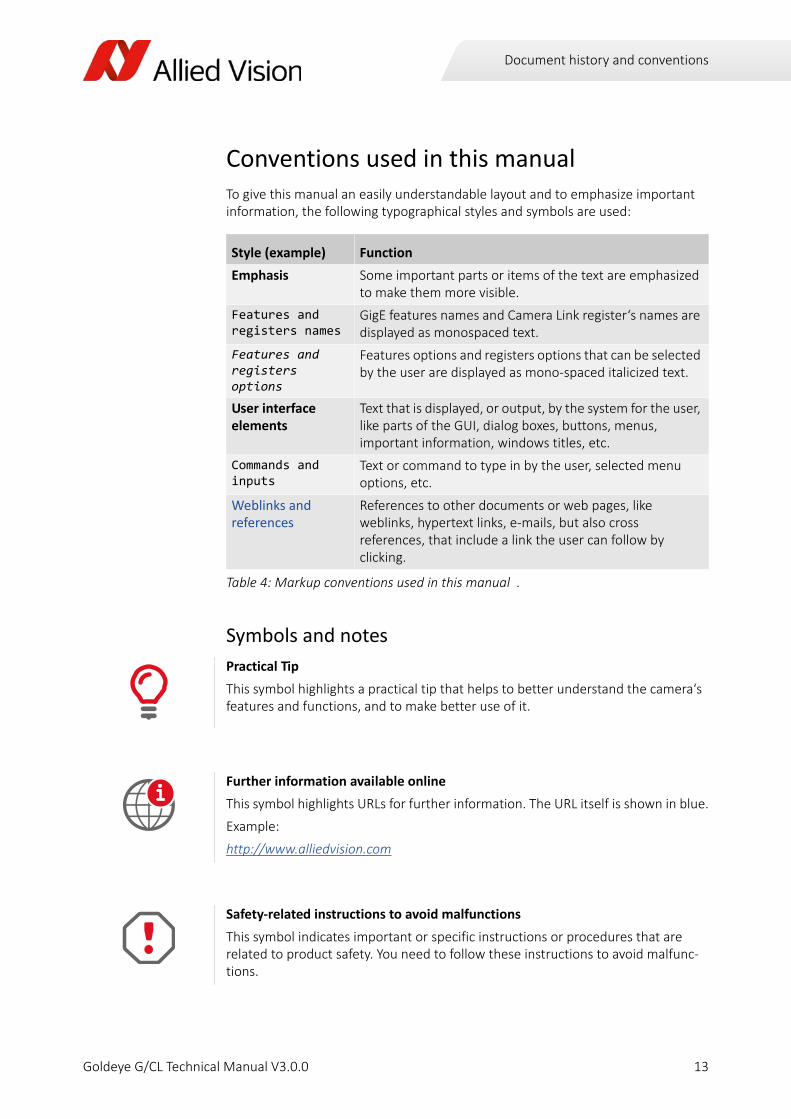
Conventions used in this manualTo give this manual an easily understandable layout and to emphasize important information, the following typographical styles and symbols are used:
Symbols and notes
Style (example) Function
Emphasis Some important parts or items of the text are emphasized to make them more visible.
Features and registers names
GigE features names and Camera Link register‘s names are displayed as monospaced text.
Features and registers options
Features options and registers options that can be selected by the user are displayed as mono‐spaced italicized text.
User interface elements
Text that is displayed, or output, by the system for the user, like parts of the GUI, dialog boxes, buttons, menus, important information, windows titles, etc.
Commands and inputs
Text or command to type in by the user, selected menu options, etc.
Weblinks and references
References to other documents or web pages, like weblinks, hypertext links, e‐mails, but also cross references, that include a link the user can follow by clicking.
Table 4: Markup conventions used in this manual .
Practical Tip
This symbol highlights a practical tip that helps to better understand the camera‘s features and functions, and to make better use of it.
Further information available online
This symbol highlights URLs for further information. The URL itself is shown in blue.
Example:
http://www.alliedvision.com
Safety‐related instructions to avoid malfunctions
This symbol indicates important or specific instructions or procedures that are related to product safety. You need to follow these instructions to avoid malfunc‐tions.
i
13Goldeye G/CL Technical Manual V3.0.0

Document history and conventions
Possible damage
This symbol is used to address important information to avoid physical or material damage; however, is not related to bodily injury.
14Goldeye G/CL Technical Manual V3.0.0
Customer assistance
Goldeye G/CL Technical Manual V3.0.0
@
This chapter includes:• References to additional Allied Vision documenta‐tion
• Contact data for technical information and support
• Commercial information

Customer assistance
Additional documentationGoldeye G/CL Features Reference GigE camera and driver features:
For detailed information on camera controls, read the Allied Vision Goldeye G/CL Features Reference document, which is available on the Allied Vision Technical Papers and Knowledge Base web page. It describes the standard and advanced cam‐era controls for GigE Vision and Camera Link SWIR cameras as seen from the Vimba Viewer or GenICam compliant 3rd‐party software solutions.
http://www.alliedvision.com/en/support/technical‐papers‐knowledge‐base.html
GigE Installation Manual:
The GigE Installation Manual describes the hardware installation procedures for Allied Vision GigE cameras. Additionally, it includes safety instructions, pin assign‐ments on I/O connectors, and GigE port connectors.
The document is available on the Allied Vision Technical Papers and Knowledge Base web page:
http://www.alliedvision.com/en/support/technical‐papers‐knowledge‐base.html
Camera Link Installation Guide:
The Camera Link Installation Guide describes the hardware installation procedures for Allied Vision Camera Link cameras. Additionally, it includes safety instructions, pin assignments on I/O connectors, and CL port connectors.
The document is available on the Allied Vision Technical Papers and Knowledge Base web page:
http://www.alliedvision.com/en/support/technical‐papers‐knowledge‐base.html
Software download:
The VIMBA SDK and Acquire Control software packages applicable to Goldeye G/CL cameras can be downloaded from the Allied Vision software website (including doc‐umentation and release notes):
http://www.alliedvision.com/en/support/software‐downloads.html
i
16Goldeye G/CL Technical Manual V3.0.0

Customer assistance
Support
Technical information and support:
To obtain further technical information and request technical support, use the link on the Allied Vision website below:
http://www.alliedvision.com/en/contact.html
If you are a registered customer you may also contact Allied Vision support via e‐mail:
i
17Goldeye G/CL Technical Manual V3.0.0

Customer assistance
Contact addresses:
EMEA
Allied Vision Technologies GmbH
Taschenweg 2a, 07646 Stadtroda, Germany
Tel: +49 36428‐677‐0
Fax: +49 36428‐677‐28
e‐mail: [email protected]
The Americas
Allied Vision Technologies Inc.
38 Washington Street, Newburyport, MA 01950, USA
Tel: +1 978‐225‐2030
Fax: +1 978‐225‐2029
e‐mail: [email protected]
Asia‐Pacific
Allied Vision Technologies Asia Pte. Ltd.
82 Playfair Road, #07‐02 D’Lithium, Singapore 368001
Tel: +65 6634‐9027
Fax: +65 6634‐9029
e‐mail: [email protected]
Mainland China
Allied Vision Technologies (Shanghai) Co., Ltd.
2‐2109 Hongwell International Plaza
1602# ZhongShanXi Road, Shanghai 200235, China
Tel: +86 (21) 64861133
Fax: +86 (21) 54233670
e‐mail: [email protected]
18Goldeye G/CL Technical Manual V3.0.0

Specifications
Goldeye G/CL Technical Manual V3.0.0
This chapter includes:
• Technical specifications, advanced features, and measured spectral sensitivity diagrams for each Goldeye G and CL camera type
• Information about sensor position accuracy of Goldeye SWIR cameras
• Frame rates that result when changing the resolution from smallest to maximum window size, listing of frame rates achievable with common video formats, and an explanation of frame rates calculation
• CAD drawings and dimensions of standard housing models including available lens mounts.

Specifications
Camera specifications
Goldeye G‐008 SWIR
Imaging / Performance
Parameter Values
Sensor InGaAs, progressive scan, electronic full frame shutter
Sensor type Focal plane array (FPA)
Spectral range 900 nm – 1700 nm
Resolution 320 (H) x 256 (V)
Cell size 30 μm x 30 μm
Effective chip size 9.6 mm x 7.68 mm
Dark current 280 keˉ/s (@ +25 °C FPA temperature)
Temporal dark noise (Gain0) 420 eˉ
Temporal dark noise (Gain1) 170 eˉ
Saturation capacity (Gain0) 2.5 Meˉ
Saturation capacity (Gain1) 170 keˉ
Dynamic range (Gain0) 75 dB
Dynamic range (Gain1) 60 dB
Pixel operability >99.5 %
Max. frame rate @ full res. 344 fps
Exposure time * 6 µs to 200 ms
Cooling Single‐stage thermoelectric cooling (TEC1)
Analog gain levels Gain0, Gain1
A/D converter 14 bit
On‐board FIFO 256 MiB, 1524 frames at full resolution
* The maximum exposure value is for Gain0 and sensor temperature of +25°C. Even longer exposures can be set, but the image quality may deteriorate.
Table 5: Goldeye G‐008 SWIR ‐ Sensor technical data
20Goldeye G/CL Technical Manual V3.0.0

Specifications
Output
General purpose inputs/outputs
Mechanics
Operating conditions
Parameter Values
Digital interface GigE Vision (based on IEEE 802.3 1000BASE‐T)
Bit depth 8 ‐ 14 bit
Pixel formats Mono8, Mono12, Mono12Packed, Mono14
Table 6: Goldeye G‐008 SWIR ‐ Output technical data
Parameter Values
Opto‐coupled I/Os 1 input, 2 outputs
RS‐232 115 200 Baud, 8N1 (adjustable)
LVTTL I/Os 1 input, 1 output
Table 7: Goldeye G‐008 SWIR ‐ General purpose inputs/outputs
Parameter Values
Body dimensions (L x W x H)w/o lens adapter
78 mm x 55 mm x 55 mm
Lens mount C‐Mount /F‐Mount /M42‐Mount available
Mass, body only, w/o adapter 320 g
Mass, w/ C‐Mount adapter 340 g
Mass, w/ F‐Mount adapter 390 g
Mass, w/ M42‐Mount adapter 360 g
Table 8: Goldeye G‐008 SWIR ‐ Mechanics specifications
Parameter Values
Case temperature ‐20 °C to +55 °C
Storage temperature ‐20 °C to +70 °C
Sensor cooling temperature, setpoints **
+20 °C, +25 °C, +35 °C, +50 °C, or user‐configurable
Table 9: Goldeye G‐008 SWIR ‐ Operating conditions
21Goldeye G/CL Technical Manual V3.0.0

Specifications
Spectral sensitivity
Temperature monitoring Available for both camera and sensor
Relative humidity 10 % to 95 %, non‐condensing
Power requirements (DC) 10.8 V to 30.0 V or via PoE
Max. power consumption <12.95 W (@ PoE), 10.8 W (@ 12 V DC)
Typical power consumption without cooling
6.5 W (@ PoE), 5 W (@ 12 V DC)
Regulations CE, FCC part 15 class B
Mechanical tests Random vibration (IEC 60068‐2‐64)Shock (IEC 60068‐2‐27)
** The first temperature setpoint may be set lower than +20 °C. However if the sensor temperature is lower than the ambient temperature, especially in humid environments, condensation may occur.
Figure 1: Spectral sensitivity Goldeye G‐008 SWIR
Parameter Values
Table 9: Goldeye G‐008 SWIR ‐ Operating conditions (continued)
22Goldeye G/CL Technical Manual V3.0.0
Specifications
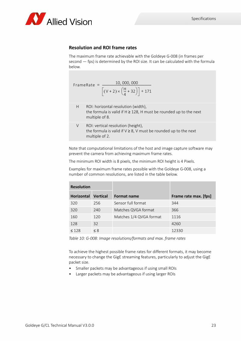
Resolution and ROI frame rates
The maximum frame rate achievable with the Goldeye G‐008 (in frames per second — fps) is determined by the ROI size. It can be calculated with the formula below.
Note that computational limitations of the host and image capture software may prevent the camera from achieving maximum frame rates.
The minimum ROI width is 8 pixels, the minimum ROI height is 4 Pixels.
Examples for maximum frame rates possible with the Goldeye G‐008, using a number of common resolutions, are listed in the table below.
To achieve the highest possible frame rates for different formats, it may become necessary to change the GigE streaming features, particularly to adjust the GigE packet size.
• Smaller packets may be advantageous if using small ROIs
• Larger packets may be advantageous if using larger ROIs
H ROI: horizontal resolution (width), the formula is valid if H ≥ 128, H must be rounded up to the next multiple of 8.
V ROI: vertical resolution (height), the formula is valid if V ≥ 8, V must be rounded up to the next multiple of 2.
Resolution
Format name Frame rate max. [fps]Horizontal Vertical
320 256 Sensor full format 344
320 240 Matches QVGA format 366
160 120 Matches 1/4 QVGA format 1116
128 32 4260
≤ 128 ≤ 8 12330
Table 10: G‐008: Image resolutions/formats and max. frame rates
FrameRate 10 000 000, ,
V 2+ H4‐‐‐‐ 32+ 171+
‐‐‐‐‐‐‐‐‐‐‐‐‐‐‐‐‐‐‐‐‐‐‐‐‐‐‐‐‐‐‐‐‐‐‐‐‐‐‐‐‐‐‐‐‐‐‐‐‐‐‐‐‐‐‐‐‐‐‐‐‐‐‐‐‐‐‐‐‐‐‐‐=
23Goldeye G/CL Technical Manual V3.0.0

Specifications
Goldeye G‐032 SWIR
Imaging / Performance
Parameter Values
Sensor InGaAs, progressive scan, electronic full frame shutter
Sensor type Focal plane array (FPA)
Spectral range 900 nm – 1700 nm
Resolution 636 (H) x 508 (V)
Cell size 25 μm x 25 μm
Effective chip size 15.9 mm x 12.7 mm
Dark current 380 keˉ/s (@ +20 °C FPA temperature)
Temporal dark noise (Gain0) 400 eˉ
Temporal dark noise (Gain1) 170 eˉ
Saturation capacity (Gain0) 1.9 Meˉ
Saturation capacity (Gain1) 39 keˉ
Dynamic range (Gain0) 73 dB
Dynamic range (Gain1) 47 dB
Pixel operability >99.5 %
Exposure time * 6 µs to 200 ms
Max. frame rate @ full res. 100 fps
Cooling Single‐stage thermoelectric cooling (TEC1)
Analog gain levels Gain0, Gain1
A/D converter 14 bit
On‐board FIFO 256 MiB, 397 frames at full resolution
* The maximum exposure value is for Gain0 and sensor temperature of +20°C. Even longer exposures can be set, but the image quality may deteriorate.
Table 11: Goldeye G‐032 SWIR ‐ Sensor technical data
24Goldeye G/CL Technical Manual V3.0.0

Specifications
Output
General purpose inputs/outputs
Mechanics
Operating conditions
Parameter Values
Digital interface GigE Vision (based on IEEE 802.3 1000BASE‐T)
Bit depth 8 ‐ 14 bit
Pixel formats Mono8, Mono12, Mono12Packed, Mono14
Table 12: Goldeye G‐032 SWIR ‐ Output technical data
Parameter Values
Opto‐coupled I/Os 1 input, 2 outputs
RS‐232 115 200 Baud, 8N1 (adjustable)
LVTTL I/Os 1 input, 1 output
Table 13: Goldeye G‐032 SWIR ‐ General purpose inputs/outputs
Parameter Values
Body dimensions (L x W x H)w/o lens adapter
78 mm x 55 mm x 55 mm
Lens mount C‐Mount /F‐Mount /M42‐Mount available
Mass, body only, w/o adapter 350 g
Mass, w/ C‐Mount adapter 370 g
Mass, w/ F‐Mount adapter 420 g
Mass, w/ M42‐Mount adapter 390 g
Table 14: Goldeye G‐032 SWIR ‐ Mechanics specifications
Parameter Values
Case temperature ‐20 °C to +55 °C
Storage temperature ‐20 °C to +70 °C
Sensor cooling temperature, setpoints
+5 °C, +20 °C, +35 °C, +50 °C, or user‐configurable
Table 15: Goldeye G‐032 SWIR ‐ Operating conditions
25Goldeye G/CL Technical Manual V3.0.0

Specifications
Temperature monitoring Available for both camera and sensor
Relative humidity 10 % to 95 %, non‐condensing
Power requirements (DC) 10.8 V to 30.0 V or via PoE
Max. power consumption <12.95 W (@ PoE), 10.8 W (@ 12 V DC)
Typical power consumption without cooling
6.5 W (@ PoE), 5 W (@ 12 V DC)
Regulations CE, FCC part 15 class B
Mechanical tests Random vibration (IEC 60068‐2‐64)Shock (IEC 60068‐2‐27)
Parameter Values
Table 15: Goldeye G‐032 SWIR ‐ Operating conditions (continued)
26Goldeye G/CL Technical Manual V3.0.0

Specifications
Goldeye G‐032 SWIR Cool
Imaging / Performance
Parameter Values
Sensor InGaAs, progressive scan, electronic full frame shutter
Sensor type Focal plane array (FPA)
Spectral range 900 nm – 1700 nm
Resolution 636 (H) x 508 (V)
Cell size 25 μm x 25 μm
Effective chip size 15.9 mm x 12.7 mm
Dark current 30 keˉ/s (@ ‐20 °C FPA temperature)
Temporal dark noise (Gain0) 400 eˉ
Temporal dark noise (Gain1) 170 eˉ
Saturation capacity (Gain0) 1.9 Meˉ
Saturation capacity (Gain1) 39 keˉ
Dynamic range (Gain0) 73 dB
Dynamic range (Gain1) 47 dB
Pixel operability >99.5 %
Exposure time * 6 µs to 1250 ms
Max. frame rate @ full res. 100 fps
Cooling Dual‐stage thermoelectric cooling (TEC2)
Analog gain levels Gain0, Gain1
A/D converter 14 bit
On‐board FIFO 256 MiB, 397 frames at full resolution
* The maximum exposure value is for Gain0 and sensor temperature of ‐20°C. Even longer exposures can be set, but the image quality may deteriorate.
Table 16: Goldeye G‐032 SWIR Cool ‐ Sensor technical data
27Goldeye G/CL Technical Manual V3.0.0

Specifications
Output
General purpose inputs/outputs
Mechanics
Operating conditions
Parameter Values
Digital interface GigE Vision (based on IEEE 802.3 1000BASE‐T)
Bit depth 8 ‐ 14 bit
Pixel formats Mono8, Mono12, Mono12Packed, Mono14
Table 17: Goldeye G‐032 SWIR Cool ‐ Output technical data
Parameter Values
Opto‐coupled I/Os 1 input, 2 outputs
RS‐232 115 200 Baud, 8N1 (adjustable)
LVTTL I/Os 1 input, 1 output
Table 18: Goldeye G‐032 SWIR Cool ‐ General purpose inputs/outputs
Parameter Values
Body dimensions (L x W x H)w/o lens adapter
90 mm x 80 mm x 80 mm
Lens mount C‐Mount /F‐Mount /M42‐Mount available
Mass, body only, w/o adapter 790 g
Mass, w/ C‐Mount adapter 810 g
Mass, w/ F‐Mount adapter 860 g
Mass, w/ M42‐Mount adapter 830 g
Table 19: Goldeye G‐032 SWIR Cool ‐ Mechanics specifications
Parameter Values
Case temperature ‐20 °C to +55 °C
Storage temperature ‐20 °C to +70 °C
Sensor cooling temperature, setpoints
‐20 °C, ‐5 °C, +10 °C, or user‐configurable
Table 20: Goldeye G‐032 SWIR Cool ‐ Operating conditions
28Goldeye G/CL Technical Manual V3.0.0
Specifications
Spectral sensitivity
Temperature monitoring Available for both camera and sensor
Relative humidity 10 % to 95 %, non‐condensing
Power requirements (DC) 10.8 V to 30.0 V or via PoE+
Max. power consumption 22 W (@ PoE+), 19 W (@ 12 V DC)
Typical power consumption without cooling
8 W (@ PoE+), 6 W (@ 12 V DC)
Regulations CE, FCC part 15 class B
Mechanical tests Random vibration (IEC 60068‐2‐64)Shock (IEC 60068‐2‐27)
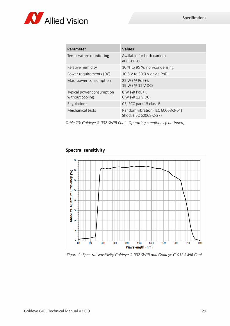
Figure 2: Spectral sensitivity Goldeye G‐032 SWIR and Goldeye G‐032 SWIR Cool
Parameter Values
Table 20: Goldeye G‐032 SWIR Cool ‐ Operating conditions (continued)
29Goldeye G/CL Technical Manual V3.0.0

Specifications
Resolution and ROI frame rates
The maximum frame rate achievable with the Goldeye G‐032 and G‐032 Cool (in frames per second — fps) is determined by the ROI size. It can be calculated with the formula below.
Note that computational limitations of the host and image capture software may prevent the camera from achieving maximum frame rates.
The minimum ROI width is 8 pixels, the minimum ROI height is 4 Pixels.
Examples for maximum frame rates possible with the Goldeye G‐032, using a number of common resolutions, are listed in the table below.
To achieve the highest possible frame rates for different formats, it may become necessary to change the GigE streaming features, particularly to adjust the GigE packet size.
• Smaller packets may be advantageous if using small ROIs
• Larger packets may be advantageous if using larger ROIs
H ROI: horizontal resolution (width), the formula is valid if H ≥ 128, H must be rounded up to the next multiple of 16.
V ROI: vertical resolution (height), the formula is valid if V ≥ 8, V must be rounded up to the next multiple of 4.
Resolution
Format name Frame rate max. [fps]Horizontal Vertical
636 508 Sensor full format 100
636 480 Approx. matches VGA format 107
320 240 Matches QVGA format 364
160 120 Matches 1/4 QVGA format 1103
≤ 128 ≤ 8 In all resolutions smaller than this the frame rate stays the same.
11123
Table 21: G‐032: Image resolutions/formats and resulting maximum frame rates
FrameRate 10 000 000, ,
V 4+ H4‐‐‐‐ 32+ 131+
‐‐‐‐‐‐‐‐‐‐‐‐‐‐‐‐‐‐‐‐‐‐‐‐‐‐‐‐‐‐‐‐‐‐‐‐‐‐‐‐‐‐‐‐‐‐‐‐‐‐‐‐‐‐‐‐‐‐‐‐‐‐‐‐‐‐‐‐‐‐‐=
30Goldeye G/CL Technical Manual V3.0.0
Specifications
Goldeye G‐033 SWIR
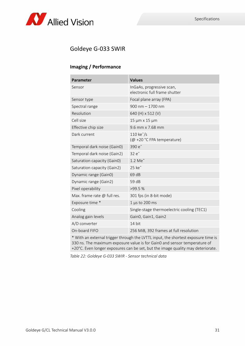
Imaging / Performance
Parameter Values
Sensor InGaAs, progressive scan, electronic full frame shutter
Sensor type Focal plane array (FPA)
Spectral range 900 nm – 1700 nm
Resolution 640 (H) x 512 (V)
Cell size 15 μm x 15 μm
Effective chip size 9.6 mm x 7.68 mm
Dark current 110 keˉ/s (@ +20 °C FPA temperature)
Temporal dark noise (Gain0) 390 eˉ
Temporal dark noise (Gain2) 32 eˉ
Saturation capacity (Gain0) 1.2 Meˉ
Saturation capacity (Gain2) 25 keˉ
Dynamic range (Gain0) 69 dB
Dynamic range (Gain2) 59 dB
Pixel operability >99.5 %
Max. frame rate @ full res. 301 fps (in 8‐bit mode)
Exposure time * 1 µs to 200 ms
Cooling Single‐stage thermoelectric cooling (TEC1)
Analog gain levels Gain0, Gain1, Gain2
A/D converter 14 bit
On‐board FIFO 256 MiB, 392 frames at full resolution
* With an external trigger through the LVTTL input, the shortest exposure time is 330 ns. The maximum exposure value is for Gain0 and sensor temperature of +20°C. Even longer exposures can be set, but the image quality may deteriorate.
Table 22: Goldeye G‐033 SWIR ‐ Sensor technical data
31Goldeye G/CL Technical Manual V3.0.0

Specifications
Output
General purpose inputs/outputs
Mechanics
Operating conditions
Parameter Values
Digital interface GigE Vision (based on IEEE 802.3 1000BASE‐T)
Bit depth 8 ‐ 14 bit
Pixel formats Mono8, Mono12, Mono12Packed, Mono14
Table 23: Goldeye G‐033 SWIR ‐ Output technical data
Parameter Values
Opto‐coupled I/Os 1 input, 2 outputs
RS‐232 115 200 Baud, 8N1 (adjustable)
LVTTL I/Os 1 input, 1 output
Table 24: Goldeye G‐033 SWIR ‐ General purpose inputs/outputs
Parameter Values
Body dimensions (L x W x H)w/o lens adapter
78 mm x 55 mm x 55 mm
Lens mount C‐Mount /F‐Mount /M42‐Mount available
Mass, body only, w/o adapter 350 g
Mass, w/ C‐Mount adapter 370 g
Mass, w/ F‐Mount adapter 430 g
Mass, w/ M42‐Mount adapter 390 g
Table 25: Goldeye G‐033 SWIR ‐ Mechanics specifications
Parameter Values
Case temperature ‐20 °C to +55 °C
Storage temperature ‐20 °C to +70 °C
Sensor cooling temperature, setpoints
+5 °C, +20 °C +35 °C, +50 °C, or user‐configurable
Table 26: Goldeye G‐033 SWIR ‐ Operating conditions
32Goldeye G/CL Technical Manual V3.0.0

Specifications
Spectral sensitivity
Temperature monitoring Available for both camera and sensor
Relative humidity 10 % to 95 %, non‐condensing
Power requirements (DC) 10.8 V to 30.0 V or via PoE
Max. power consumption <12.95 W (@ PoE), 10.8 W (@ 12 V DC)
Typical power consumption without cooling
8 W (@ PoE), 6.3W (@ 12 V DC)
Regulations CE, FCC part 15 class B
Mechanical tests Random vibration (IEC 60068‐2‐64)Shock (IEC 60068‐2‐27)
Figure 3: Spectral sensitivity Goldeye G‐033 SWIR
Parameter Values
Table 26: Goldeye G‐033 SWIR ‐ Operating conditions (continued)
33Goldeye G/CL Technical Manual V3.0.0

Specifications
Resolution and ROI frame rate
The maximum frame rate achievable with the Goldeye G‐033 (in frames per second — fps) is determined by the ROI size. It can be calculated with the formula below.
Note that computational limitations of the host and image capture software may prevent the camera from achieving maximum frame rates.
The minimum ROI width is 8 pixels, the minimum ROI height is 4 Pixels.
Examples for maximum frame rates possible with the Goldeye G‐033, using a number of common resolutions, are listed in the table below.
To achieve the highest possible frame rates for different formats, it may become necessary to change the GigE streaming features, particularly to adjust the GigE packet size.
• Smaller packets may be advantageous if using small ROIs
• Larger packets may be advantageous if using larger ROIs
H ROI: horizontal resolution (width), the formula is valid if H ≥ 32, H must be rounded up to the next multiple of 32.
V ROI: vertical resolution (height), the formula is valid if V ≥ 4, V must be rounded up to the next multiple of 4.
Resolution
Format name Frame rate max. [fps]Horizontal Vertical
640 512 Sensor full format 301 (8‐bit mode)
640 480 Matches VGA format 321 (8‐bit mode)
320 240 Matches QVGA format 968 (8‐bit mode)
160 120 Matches 1/4 QVGA format 2556 (8‐bit or 12‐bit)
≤ 128 ≤ 24 >11500 (8‐bit mode)
Table 27: G‐033: Image resolutions/formats and max. frame rates
FrameRate 18 000 000, ,
V 1+ H8‐‐‐‐ 36+ 265+
‐‐‐‐‐‐‐‐‐‐‐‐‐‐‐‐‐‐‐‐‐‐‐‐‐‐‐‐‐‐‐‐‐‐‐‐‐‐‐‐‐‐‐‐‐‐‐‐‐‐‐‐‐‐‐‐‐‐‐‐‐‐‐‐‐‐‐‐‐‐‐=
34Goldeye G/CL Technical Manual V3.0.0

Specifications
Goldeye CL‐008 SWIR
Imaging / Performance
Parameter Values
Sensor InGaAs, progressive scan, electronic full frame shutter
Sensor type Focal plane array (FPA)
Spectral range 900 nm – 1700 nm
Resolution 320 (H) x 256 (V)
Cell size 30 μm x 30 μm
Effective chip size 9.6 mm x 7.68 mm
Dark current 280 keˉ/s (@ +25 °C FPA temperature)
Temporal dark noise (Gain0) 420 eˉ
Temporal dark noise (Gain1) 170 eˉ
Saturation capacity (Gain0) 2.5 Meˉ
Saturation capacity (Gain1) 170 keˉ
Dynamic range (Gain0) 75 dB
Dynamic range (Gain1) 60 dB
Pixel operability >99.5 %
Max. frame rate @ full res. 344 fps
Exposure time * 6 µs to 200 ms
Cooling Single‐stage thermoelectric cooling (TEC1)
Analog gain levels Gain0, Gain1
A/D converter 14 bit
On‐board FIFO 256 MiB, 1524 frames at full resolution
* The maximum exposure value is for Gain0 and sensor temperature of +25°C. Even longer exposures can be set, but the image quality may deteriorate.
Table 28: Goldeye CL‐008 SWIR ‐ Sensor technical data
35Goldeye G/CL Technical Manual V3.0.0

Specifications
Output
General purpose inputs/outputs
Mechanics
Operating conditions
Parameter Values
Digital interface Camera Link Base, up to 2 taps, 40 MHz, SDR26 connector, Serial Control Channel
Bit depth 8 ‐ 14 bit
Pixel formats Tap Geometry 1X 1Y: Mono8, Mono12, Mono14 Tap Geometry 1X2 1Y: Mono8, Mono12
Table 29: Goldeye CL‐008 SWIR ‐ Output technical data
Parameter Values
Opto‐coupled I/Os 1 input, 2 outputs
RS‐232 115 200 Baud, 8N1 (adjustable)
LVTTL I/Os 1 input, 1 output
LVDS Inputs CC1 ‐ CC4
Table 30: Goldeye CL‐008 SWIR ‐ General purpose inputs/outputs
Parameter Values
Body dimensions (L x W x H)w/o lens adapter
78 mm x 55 mm x 55 mm
Lens mount C‐Mount /F‐Mount /M42‐Mount available
Mass, body only, w/o adapter 300 g
Mass, w/ C‐Mount adapter 320 g
Mass, w/ F‐Mount adapter 370 g
Mass, w/ M42‐Mount adapter 340 g
Table 31: Goldeye CL‐008 SWIR ‐ Mechanics specifications
Parameter Values
Case temperature ‐20 °C to +55 °C
Storage temperature ‐20 °C to +70 °C
Table 32: Goldeye CL‐008 SWIR ‐ Operating conditions
36Goldeye G/CL Technical Manual V3.0.0

Specifications
Spectral sensitivity
Sensor cooling temperature, setpoints **
+20 °C, +25 °C, +35 °C, +50 °C, or user‐configurable
Temperature monitoring Available for both camera and sensor
Relative humidity 10 % to 95 %, non‐condensing
Power requirements (DC) 10.8 V to 30.0 V
Max. power consumption 10 W (@ 12 V DC)
Typical power consumption without cooling
4.5 W (@ 12 V DC)
Regulations CE, FCC part 15 class B
Mechanical tests Random vibration (IEC 60068‐2‐64)Shock (IEC 60068‐2‐27)
** The first temperature setpoint may be set lower than +20 °C. However if the sensor temperature is lower than the ambient temperature, especially in humid environments, condensation may occur.
Figure 4: Spectral sensitivity Goldeye CL‐008 SWIR
Parameter Values
Table 32: Goldeye CL‐008 SWIR ‐ Operating conditions (continued)
37Goldeye G/CL Technical Manual V3.0.0

Specifications
Resolution and ROI frame rates
The maximum frame rate achievable with the Goldeye CL‐008 (in frames per second — fps) is determined by the ROI size. It can be calculated with the formula below.
Note that computational limitations of the host and image capture software may prevent the camera from achieving maximum frame rates.
The minimum ROI width is 8 pixels, the minimum ROI height is 4 Pixels.
Examples for maximum frame rates possible with the Goldeye CL‐008, using a number of common resolutions, are listed in the table below.
H ROI: horizontal resolution (width), the formula is valid if H ≥ 128, H must be rounded up to the next multiple of 8.
V ROI: vertical resolution (height), the formula is valid if V ≥ 8, V must be rounded up to the next multiple of 2.
Resolution
Format name Frame rate max. [fps]Horizontal Vertical
320 256 Sensor full format 344
320 240 Matches QVGA format 366
160 120 Matches 1/4 QVGA format 1116
128 32 4260
≤ 128 ≤ 8 12330
Table 33: CL‐008: Image resolutions/formats and max. frame rates
FrameRate 10 000 000, ,
V 2+ H4‐‐‐‐ 32+ 171+
‐‐‐‐‐‐‐‐‐‐‐‐‐‐‐‐‐‐‐‐‐‐‐‐‐‐‐‐‐‐‐‐‐‐‐‐‐‐‐‐‐‐‐‐‐‐‐‐‐‐‐‐‐‐‐‐‐‐‐‐‐‐‐‐‐‐‐‐‐‐‐‐=
38Goldeye G/CL Technical Manual V3.0.0
Specifications
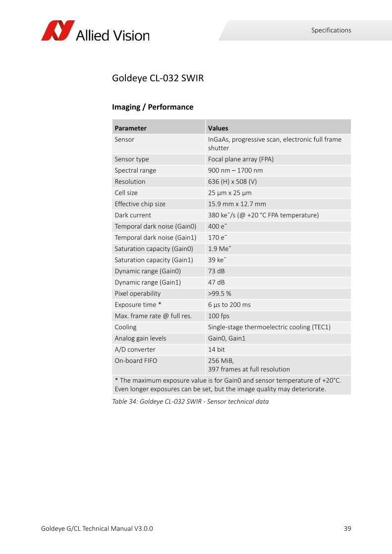
Goldeye CL‐032 SWIR
Imaging / Performance
Parameter Values
Sensor InGaAs, progressive scan, electronic full frame shutter
Sensor type Focal plane array (FPA)
Spectral range 900 nm – 1700 nm
Resolution 636 (H) x 508 (V)
Cell size 25 μm x 25 μm
Effective chip size 15.9 mm x 12.7 mm
Dark current 380 keˉ/s (@ +20 °C FPA temperature)
Temporal dark noise (Gain0) 400 eˉ
Temporal dark noise (Gain1) 170 eˉ
Saturation capacity (Gain0) 1.9 Meˉ
Saturation capacity (Gain1) 39 keˉ
Dynamic range (Gain0) 73 dB
Dynamic range (Gain1) 47 dB
Pixel operability >99.5 %
Exposure time * 6 µs to 200 ms
Max. frame rate @ full res. 100 fps
Cooling Single‐stage thermoelectric cooling (TEC1)
Analog gain levels Gain0, Gain1
A/D converter 14 bit
On‐board FIFO 256 MiB, 397 frames at full resolution
* The maximum exposure value is for Gain0 and sensor temperature of +20°C. Even longer exposures can be set, but the image quality may deteriorate.
Table 34: Goldeye CL‐032 SWIR ‐ Sensor technical data
39Goldeye G/CL Technical Manual V3.0.0

Specifications
Output
General purpose inputs/outputs
Mechanics
Operating conditions
Parameter Values
Digital interface Camera Link Base, up to 2 taps, 40 MHz, SDR26 connector, Serial Control Channel
Bit depth 8 ‐ 14 bit
Pixel formats Tap Geometry 1X 1Y: Mono8, Mono12, Mono14 Tap Geometry 1X2 1Y: Mono8, Mono12
Table 35: Goldeye CL‐32 SWIR ‐ Output technical data
Parameter Values
Opto‐coupled I/Os 1 input, 2 outputs
RS‐232 115 200 Baud, 8N1 (adjustable)
LVTTL I/Os 1 input, 1 output
LVDS Inputs CC1 ‐ CC4
Table 36: Goldeye CL‐032 SWIR ‐ General purpose inputs/outputs
Parameter Values
Body dimensions (L x W x H)w/o lens adapter
78 mm x 55 mm x 55 mm
Lens mount C‐Mount /F‐Mount /M42‐Mount available
Mass, body only, w/o adapter 320 g
Mass, w/ C‐Mount adapter 340 g
Mass, w/ F‐Mount adapter 400 g
Mass, w/ M42‐Mount adapter 360 g
Table 37: Goldeye CL‐032 SWIR ‐ Mechanics specifications
Parameter Values
Case temperature ‐20 °C to +55 °C
Storage temperature ‐20 °C to +70 °C
Table 38: Goldeye CL‐032 SWIR ‐ Operating conditions
40Goldeye G/CL Technical Manual V3.0.0
Specifications
Spectral sensitivity
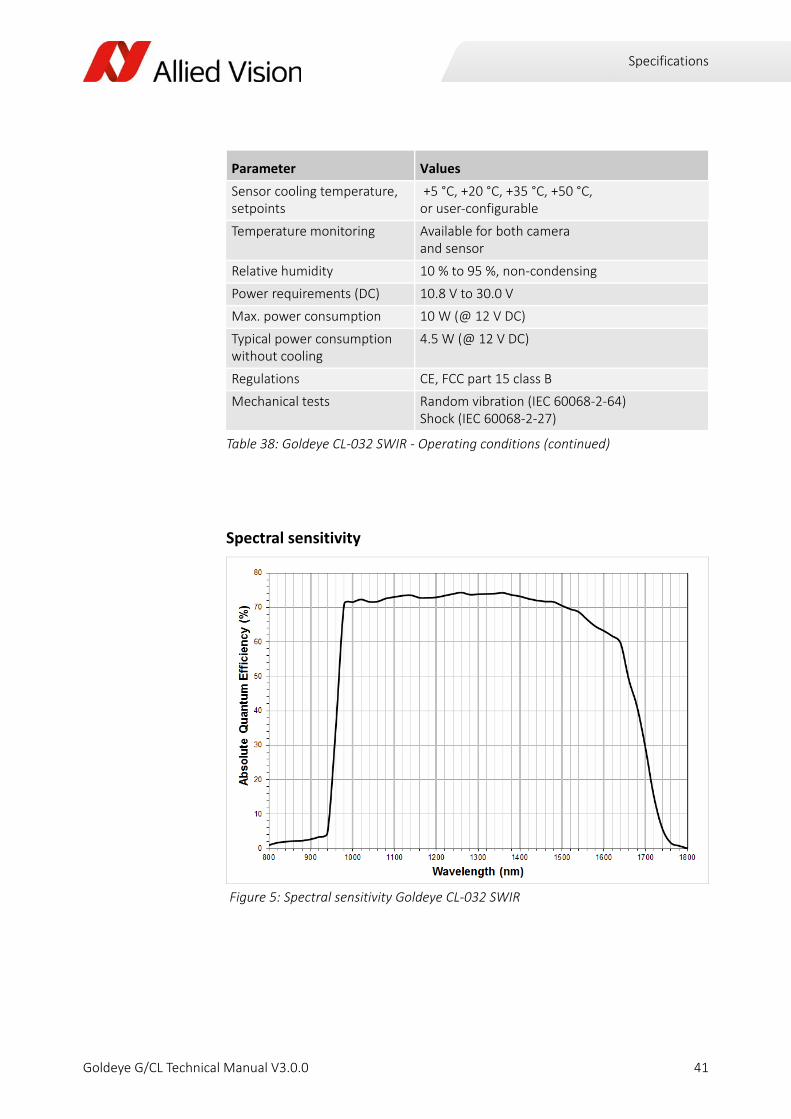
Sensor cooling temperature, setpoints
+5 °C, +20 °C, +35 °C, +50 °C, or user‐configurable
Temperature monitoring Available for both camera and sensor
Relative humidity 10 % to 95 %, non‐condensing
Power requirements (DC) 10.8 V to 30.0 V
Max. power consumption 10 W (@ 12 V DC)
Typical power consumptionwithout cooling
4.5 W (@ 12 V DC)
Regulations CE, FCC part 15 class B
Mechanical tests Random vibration (IEC 60068‐2‐64)Shock (IEC 60068‐2‐27)
Figure 5: Spectral sensitivity Goldeye CL‐032 SWIR
Parameter Values
Table 38: Goldeye CL‐032 SWIR ‐ Operating conditions (continued)
41Goldeye G/CL Technical Manual V3.0.0
Specifications
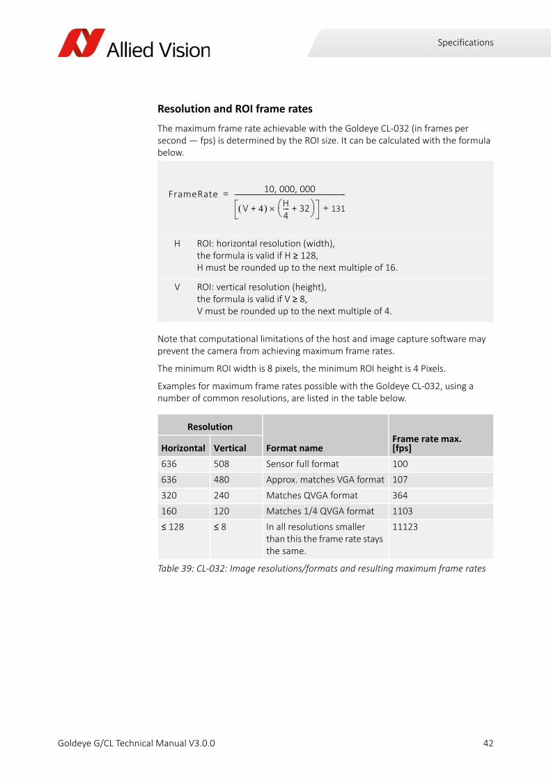
Resolution and ROI frame rates
The maximum frame rate achievable with the Goldeye CL‐032 (in frames per second — fps) is determined by the ROI size. It can be calculated with the formula below.
Note that computational limitations of the host and image capture software may prevent the camera from achieving maximum frame rates.
The minimum ROI width is 8 pixels, the minimum ROI height is 4 Pixels.
Examples for maximum frame rates possible with the Goldeye CL‐032, using a number of common resolutions, are listed in the table below.
H ROI: horizontal resolution (width), the formula is valid if H ≥ 128, H must be rounded up to the next multiple of 16.
V ROI: vertical resolution (height), the formula is valid if V ≥ 8, V must be rounded up to the next multiple of 4.
Resolution
Format nameFrame rate max.[fps]Horizontal Vertical
636 508 Sensor full format 100
636 480 Approx. matches VGA format 107
320 240 Matches QVGA format 364
160 120 Matches 1/4 QVGA format 1103
≤ 128 ≤ 8 In all resolutions smaller than this the frame rate stays the same.
11123
Table 39: CL‐032: Image resolutions/formats and resulting maximum frame rates
FrameRate 10 000 000, ,
V 4+ H4‐‐‐‐ 32+ 131+
‐‐‐‐‐‐‐‐‐‐‐‐‐‐‐‐‐‐‐‐‐‐‐‐‐‐‐‐‐‐‐‐‐‐‐‐‐‐‐‐‐‐‐‐‐‐‐‐‐‐‐‐‐‐‐‐‐‐‐‐‐‐‐‐‐‐‐‐‐‐‐=
42Goldeye G/CL Technical Manual V3.0.0

Specifications
Goldeye CL‐033 SWIR
Imaging / Performance
Parameter Values
Sensor InGaAs, progressive scan, electronic full frame shutter
Sensor type Focal plane array (FPA)
Spectral range 900 nm – 1700 nm
Resolution 640 (H) x 512 (V)
Cell size 15 μm x 15 μm
Effective chip size 9.6 mm x 7.68 mm
Dark current 110 keˉ/s (@ +20 °C FPA temperature)
Temporal dark noise (Gain0) 390 eˉ
Temporal dark noise (Gain2) 32 eˉ
Saturation capacity (Gain0) 1.2 Meˉ
Saturation capacity (Gain2) 25 keˉ
Dynamic range (Gain0) 69 dB
Dynamic range (Gain2) 59 dB
Pixel operability >99.5 %
Max. frame rate at full resolution
301 fps (in 8‐bit mode)
Exposure time * 1 µs to 200 ms
Cooling Single‐stage thermoelectric cooling (TEC1)
Analog gain levels Gain0, Gain1, Gain2
A/D converter 14 bit
On‐board FIFO 256 MiB, 392 frames at full resolution
* With an external trigger through the LVTTL input, the shortest exposure time is 330 ns. The maximum exposure value is for Gain0 and sensor temperature of +20°C. Even longer exposures can be set, but the image quality may deteriorate.
Table 40: Goldeye CL‐033 SWIR ‐ Sensor technical data
43Goldeye G/CL Technical Manual V3.0.0
Specifications
Output
General purpose inputs/outputs
Mechanics
Operating conditions
Parameter Values
Digital interface Camera Link Base, up to 2 taps, 85 MHz, SDR26 connector, Serial Control Channel
Bit depth 8 ‐ 14 bit
Pixel formats Tap Geometry 1X 1Y: Mono8, Mono12, Mono14 Tap Geometry 1X2 1Y: Mono8, Mono12
Table 41: Goldeye CL‐033 SWIR ‐ Output technical data
Parameter Values
Opto‐coupled I/Os 1 input, 2 outputs
RS‐232 115 200 Baud, 8N1 (adjustable)
LVTTL I/Os 1 input, 1 output
LVDS Inputs CC1 ‐ CC4
Table 42: Goldeye CL‐033 SWIR ‐ General purpose inputs/outputs
Parameter Values
Body dimensions (L x W x H)w/o lens adapter
78 mm x 55 mm x 55 mm
Lens mount C‐Mount /F‐Mount /M42‐Mount available
Mass, body only, w/o adapter 330 g
Mass, w/ C‐Mount adapter 350 g
Mass, w/ F‐Mount adapter 400 g
Mass, w/ M42‐Mount adapter 370 g
Table 43: Goldeye CL‐033 SWIR ‐ Mechanics specifications
Parameter Values
Case temperature ‐20 °C to +55 °C
Storage temperature ‐20 °C to +70 °C
Table 44: Goldeye CL‐033 SWIR ‐ Operating conditions
44Goldeye G/CL Technical Manual V3.0.0
Specifications
Spectral sensitivity
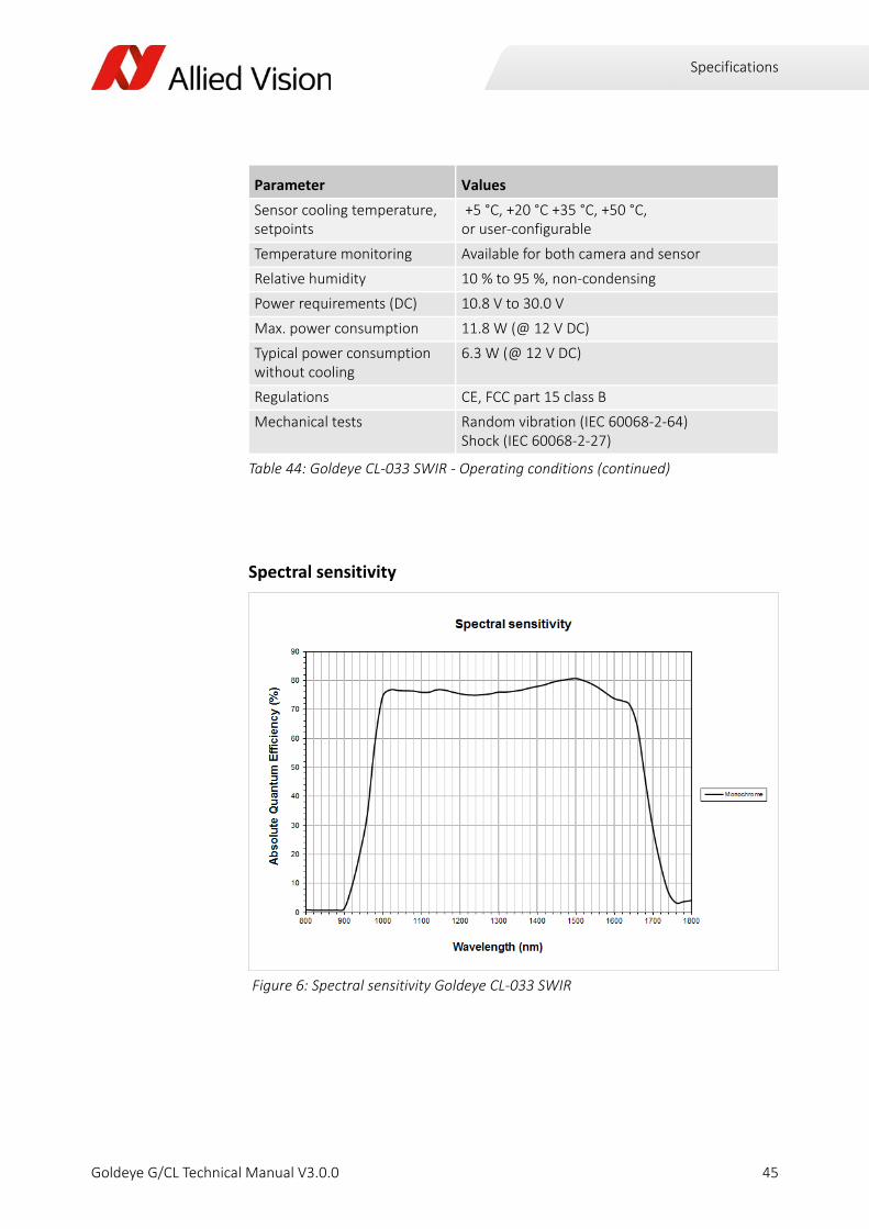
Sensor cooling temperature, setpoints
+5 °C, +20 °C +35 °C, +50 °C, or user‐configurable
Temperature monitoring Available for both camera and sensor
Relative humidity 10 % to 95 %, non‐condensing
Power requirements (DC) 10.8 V to 30.0 V
Max. power consumption 11.8 W (@ 12 V DC)
Typical power consumption without cooling
6.3 W (@ 12 V DC)
Regulations CE, FCC part 15 class B
Mechanical tests Random vibration (IEC 60068‐2‐64)Shock (IEC 60068‐2‐27)
Figure 6: Spectral sensitivity Goldeye CL‐033 SWIR
Parameter Values
Table 44: Goldeye CL‐033 SWIR ‐ Operating conditions (continued)
45Goldeye G/CL Technical Manual V3.0.0

Specifications
Resolution and ROI frame rate
The maximum frame rate achievable with the Goldeye CL‐033 (in frames per second — fps) is determined by the ROI size. It can be calculated with the formula below.
Note that computational limitations of the host and image capture software may prevent the camera from achieving maximum frame rates.
The minimum ROI width is 8 pixels, the minimum ROI height is 4 Pixels.
Examples for maximum frame rates possible with the Goldeye CL‐033, using a number of common resolutions, are listed in the table below.
H ROI: horizontal resolution (width), the formula is valid if H ≥ 32, H must be rounded up to the next multiple of 32.
V ROI: vertical resolution (height), the formula is valid if V ≥ 4, V must be rounded up to the next multiple of 4.
Resolution
Format name Frame rate max. [fps]Horizontal Vertical
640 512 Sensor full format 301 (DeviceTapGeometry = Geometry_2X_1Y)
640 480 Matches VGA format 321 (DeviceTapGeometry = Geometry_2X_1Y)
320 240 Matches QVGA format 968 (DeviceTapGeometry = Geometry_2X_1Y)
160 120 Matches 1/4 QVGA format 2556
≤ 128 ≤ 24 >11500
Table 45: CL‐033: Image resolutions/formats and max. frame rates
FrameRate 18 000 000, ,
V 1+ H8‐‐‐‐ 36+ 265+
‐‐‐‐‐‐‐‐‐‐‐‐‐‐‐‐‐‐‐‐‐‐‐‐‐‐‐‐‐‐‐‐‐‐‐‐‐‐‐‐‐‐‐‐‐‐‐‐‐‐‐‐‐‐‐‐‐‐‐‐‐‐‐‐‐‐‐‐‐‐‐=
46Goldeye G/CL Technical Manual V3.0.0
Specifications
Camera dimensions
Mounting the camera
You can attach the camera to a base in two ways:
1. To attach the camera to any horizontal or vertical base, four mounting threads M4 x 6 mm are located on each side of the camera, except for the back side.
‐ Refer to the drawings below for the exact distances between the mounting threads.
‐ To avoid damaging the camera housing, we recommend to use bolts with an effective length of 4 to 6 mm and apply a maximum torque of 2.0 Nm to each bolt.
2. To attach the camera to the common mounting plate of tripods used in pho‐tography, a 1/4 ‐ 20 UNC mounting thread is located on the camera bottom.
Caution:Ensure the camera does not disengage from base.
The camera can disengage from its base and fall down if not properly attached.
Attach the camera either with four metal bolts with an effective length of not less than 4 mm and apply a torque of 2.0 Nm to each bolt, or use the UNC thread and a mechanical safe guard.
47Goldeye G/CL Technical Manual V3.0.0

Specifications
Camera dimensions
Goldeye CL‐008 SWIR C‐Mount,Goldeye CL‐032 SWIR C‐Mount,Goldeye CL‐033 SWIR C‐Mount
Figure 7: Dimensions of the Goldeye CL with C‐Mount lens adapter
93.2
91.7
78
86.9
M4 - 6 (4x)
31
14.8
19.1
29.
5
9.6 9.6
M4 - 6 (4x)
36
36
55
55
C-Mount
M4 - 6 (4x)
1/4-20 UNC - 8
4.5 - 1.5
68 6
36
13 9
M4 - 6 (4x)
43
.9
48Goldeye G/CL Technical Manual V3.0.0

Specifications
Camera dimensions
Goldeye CL‐008 SWIR F‐Mount,Goldeye CL‐032 SWIR F‐Mount,Goldeye CL‐033 SWIR F‐Mount
Figure 8: Dimensions of the Goldeye CL with F‐Mount lens adapter
122.1
120.7
78
115.8
M4 - 6 (4x)
31
14.8
19.1
29.
5
9.6 9.6
M4 - 6 (4x)
1/4-20 UNC - 8
4.5 - 1.5
68 6
36
13 9
M4 - 6 (4x)
60
43
.9
36
36
55
55
M4 - 6 (4x)
49Goldeye G/CL Technical Manual V3.0.0

Specifications
Camera dimensions
Goldeye CL‐008 SWIR M42‐Mount,Goldeye CL‐032 SWIR M42‐Mount,Goldeye CL‐033 SWIR M42‐Mount
Figure 9: Dimensions of the Goldeye CL with M42‐Mount lens adapter
121.1
119.7
78
114.8
M4 - 6 (4x)
31
14.8
19.1
29.
5
9.6 9.6
M4 - 6 (4x)
36
36
55
55
M42-Mount
M4 - 6 (4x)
1/4-20 UNC - 8
4.5 - 1.5
68 6
36
13 9
M4 - 6 (4x)
43
.9
50Goldeye G/CL Technical Manual V3.0.0

Specifications
Camera dimensions
Goldeye G‐008 SWIR C‐Mount,Goldeye G‐032 SWIR C‐Mount,Goldeye G‐033 SWIR C‐Mount
Figure 10: Dimensions of the standard Goldeye G with C‐Mount lens adapter
7886.993.2
M4 - 6 (4x)
55
55
36
36
M4 - 6 (4x)C-Mount
14.8
1010
33.2
31
18
10 10
M2 - 5 (4x)
36
68 6
9
1/4-20 UNC - 8
M4 - 6 (4x)13Ø 4.5 - 1.5
M4 - 6 (4x)
Ø43
.9
51Goldeye G/CL Technical Manual V3.0.0

Specifications
Camera dimensions
Goldeye G‐008 SWIR F‐Mount,Goldeye G‐032 SWIR F‐Mount,Goldeye G‐033 SWIR F‐Mount
Figure 11: Dimensions of the standard Goldeye G with F‐Mount lens adapter
78115.8122.1
M4 - 6 (4x)
14.8
1010
33.2
31
18
10 10
M2 - 5 (4x)
36
68 6
9
1/4-20 UNC - 8
M4 - 6 (4x)13Ø 4.5 - 1.5
F-Mount
M4 - 6 (4x)
Ø60
Ø43
.9
M4 - 6 (4x)
5536
55 36
52Goldeye G/CL Technical Manual V3.0.0
Specifications
Camera dimensions
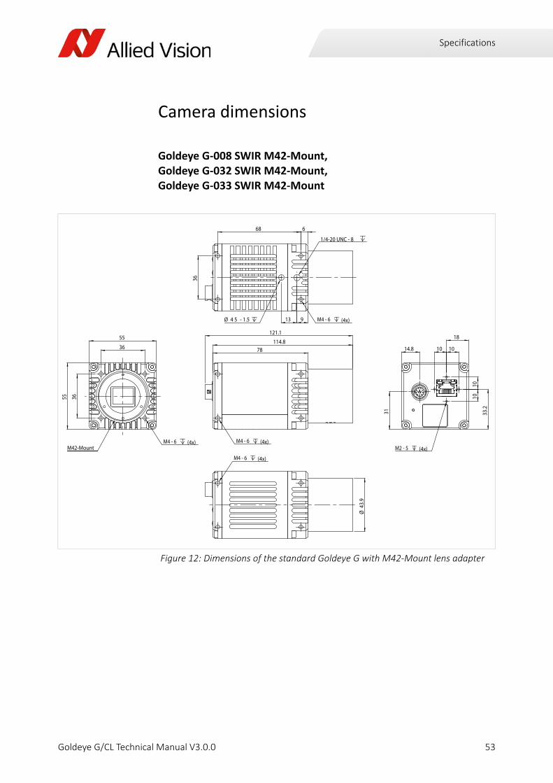
Goldeye G‐008 SWIR M42‐Mount,Goldeye G‐032 SWIR M42‐Mount,Goldeye G‐033 SWIR M42‐Mount
Figure 12: Dimensions of the standard Goldeye G with M42‐Mount lens adapter
M4 - 6 (4x)
78114.8
121.1
M4 - 6 (4x)
36
36
55
55
M42-Mount M2 - 5 (4x)
14.8
18
10 10
33.2
1010
31
M4 - 6 (4x)
1/4-20 UNC - 8
913
668
36
Ø 4 5 - 1.5
M4 - 6 (4x)
Ø43
.9
53Goldeye G/CL Technical Manual V3.0.0

Specifications
Camera dimensions
Goldeye G‐032 SWIR Cool C‐Mount
Figure 13: Dimensions Goldeye G‐032 Cool with C‐Mount lens adapter
90
M4 - 6 (4x)
50
99.5105.8
80 4.3
1313
M4 - 6 (4x)
Ø 4.5 - 1.5
501/4-20 UNC - 8
80
80
50
50
M4 - 6 (4x)M42-Mount
27.3
43.5
18
30.5
45.7
1010
10 10
M2 - 5 (4x)
M4 - 6 (4x)
50
Ø43
.9
54Goldeye G/CL Technical Manual V3.0.0

Specifications
Camera dimensions
Goldeye G‐032 SWIR Cool F‐Mount
Figure 14: Dimensions Goldeye G‐032 Cool with F‐Mount lens adapter
90
M4 - 6 (4x)
50
128.4134.7
80 4.3
1313M4 - 6 (4x)
Ø 4.5 - 1.5
501/4-20 UNC - 8
80
80
50
50
M4 - 6 (4x)
F-Mount
27.3
43.5
18
30.5
45.7
1010
10 10
M2 - 5 (4x)
M4 - 6 (4x)
50
Ø43
,9
Ø60
55Goldeye G/CL Technical Manual V3.0.0
Specifications
Camera dimensions
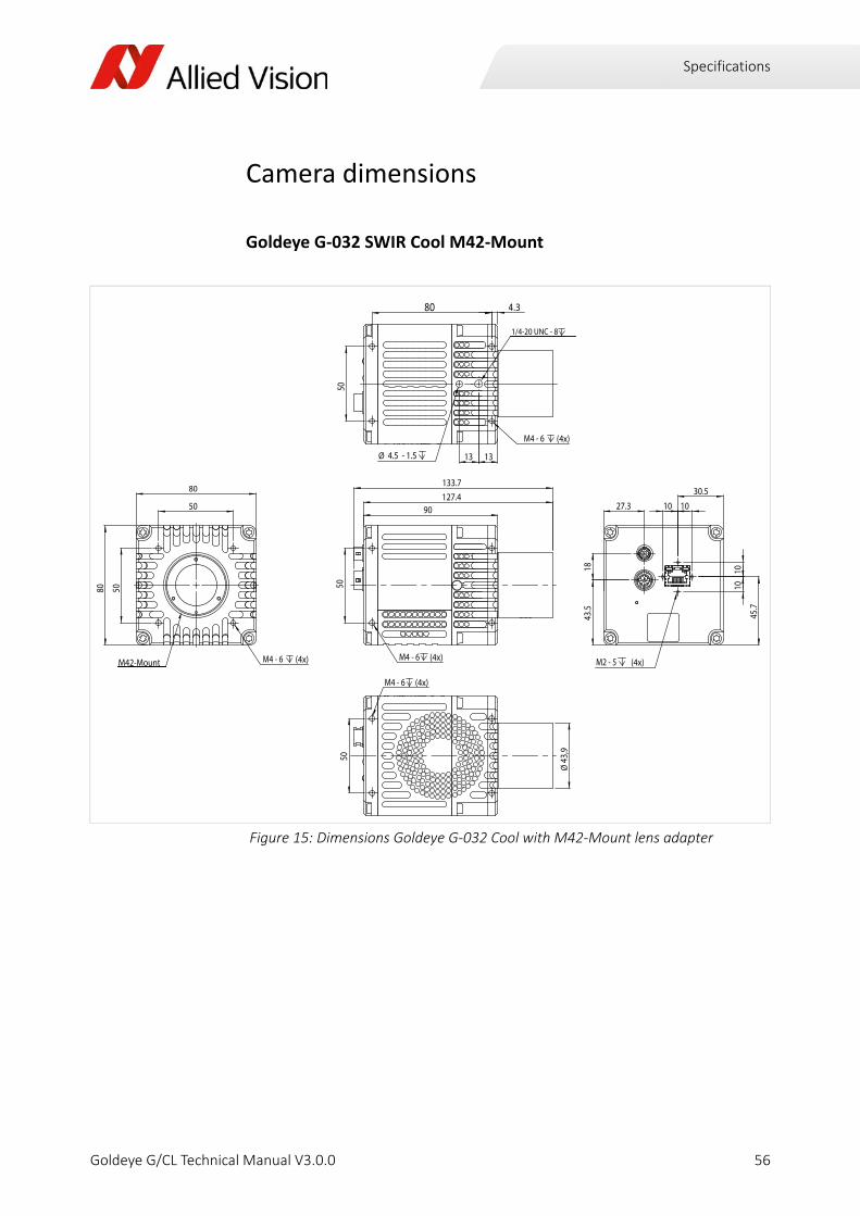
Goldeye G‐032 SWIR Cool M42‐Mount
Figure 15: Dimensions Goldeye G‐032 Cool with M42‐Mount lens adapter
90
M4 - 6 (4x)
50
127.4133.7
80 4.3
1313
M4 - 6 (4x)
Ø 4.5 - 1.5
501/4-20 UNC - 8
80
80
50
50
M4 - 6 (4x)M42-Mount
27.3
43.5
18
30.5
45.7
1010
10 10
M2 - 5 (4x)
M4 - 6 (4x)
50
Ø43
,9
56Goldeye G/CL Technical Manual V3.0.0

Specifications
Sensor position accuracy
Method of positioning
Optical alignment of the photo sensitive sensor area into the camera front module (lens mount front flange).
Reference points
Sensor: center of the pixel area (photo sensitive cells) = intersection of the lines a and b.
Camera: Center of the camera front flange (outer case edges) = intersection of lines A and B.
Accuracy
The accuracy requirements outlined in the table below must be observed for all positioning tasks.
X/Y ‐ tolerances
x/y ‐ tolerances between the C‐Mount hole and the pixel area may be higher.
Figure 16: Sensor position accuracy
Sensor shift x / y ± 150 µm
Optical back focal length z + 0 µm to ‐ 200 µm
Sensor rotation α ± 0.5 o
57Goldeye G/CL Technical Manual V3.0.0
Accessories
Goldeye G/CL Technical Manual V3.0.0
This chapter includes details about accessories available for Goldeye cameras.
• Ethernet adapters
• Power adapters
• Hirose connectors
• Other accessories
Accessories
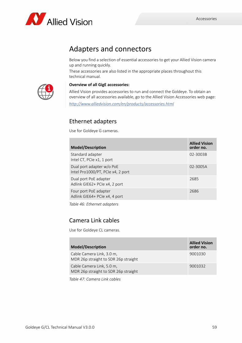
Adapters and connectorsBelow you find a selection of essential accessories to get your Allied Vision camera up and running quickly.
These accessories are also listed in the appropriate places throughout this technical manual.
Ethernet adapters
Use for Goldeye G cameras.
Camera Link cables
Use for Goldeye CL cameras.
Overview of all GigE accessories:
Allied Vision provides accessories to run and connect the Goldeye. To obtain an overview of all accessories available, go to the Allied Vision Accessories web page:
http://www.alliedvision.com/en/products/accessories.html
Model/DescriptionAllied Vision order no.
Standard adapterIntel CT, PCIe x1, 1 port
02‐3003B
Dual port adapter w/o PoEIntel Pro1000/PT, PCIe x4, 2 port
02‐3005A
Dual port PoE adapterAdlink GIE62+ PCIe x4, 2 port
2685
Four port PoE adapterAdlink GIE64+ PCIe x4, 4 port
2686
Table 46: Ethernet adapters
Model/DescriptionAllied Vision order no.
Cable Camera Link, 3.0 m, MDR 26p straight to SDR 26p straight
9001030
Cable Camera Link, 5.0 m, MDR 26p straight to SDR 26p straight
9001032
Table 47: Camera Link cables
i
59Goldeye G/CL Technical Manual V3.0.0
Accessories
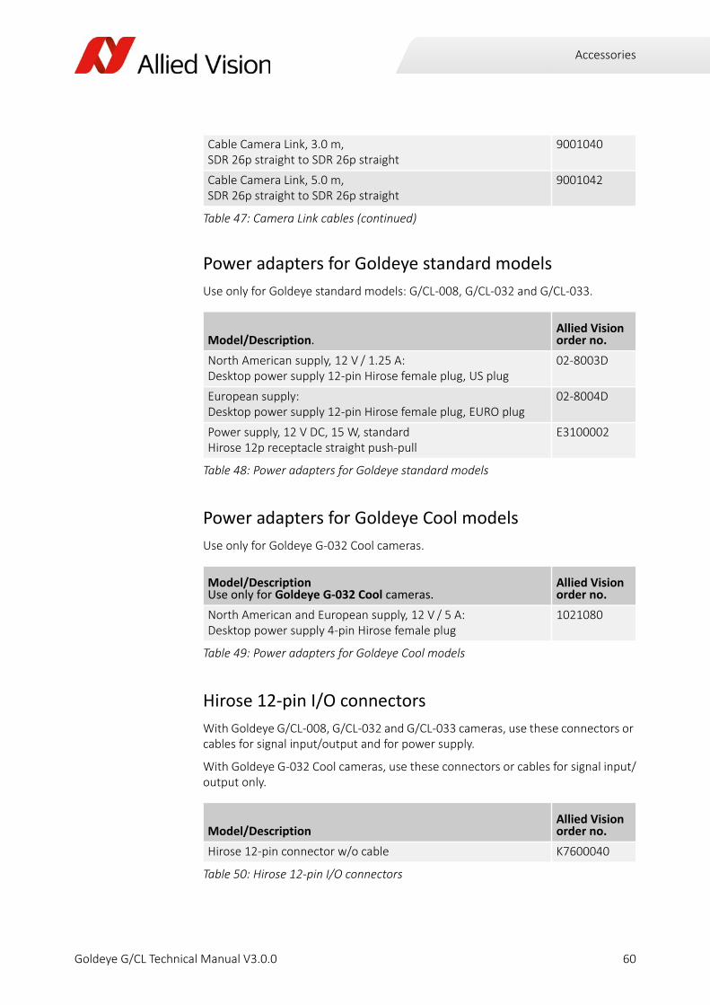
Power adapters for Goldeye standard models
Use only for Goldeye standard models: G/CL‐008, G/CL‐032 and G/CL‐033.
Power adapters for Goldeye Cool models
Use only for Goldeye G‐032 Cool cameras.
Hirose 12‐pin I/O connectors
With Goldeye G/CL‐008, G/CL‐032 and G/CL‐033 cameras, use these connectors or cables for signal input/output and for power supply.
With Goldeye G‐032 Cool cameras, use these connectors or cables for signal input/output only.
Cable Camera Link, 3.0 m, SDR 26p straight to SDR 26p straight
9001040
Cable Camera Link, 5.0 m, SDR 26p straight to SDR 26p straight
9001042
Model/Description.Allied Vision order no.
North American supply, 12 V / 1.25 A:Desktop power supply 12‐pin Hirose female plug, US plug
02‐8003D
European supply:Desktop power supply 12‐pin Hirose female plug, EURO plug
02‐8004D
Power supply, 12 V DC, 15 W, standardHirose 12p receptacle straight push‐pull
E3100002
Table 48: Power adapters for Goldeye standard models
Model/DescriptionUse only for Goldeye G‐032 Cool cameras.
Allied Vision order no.
North American and European supply, 12 V / 5 A:Desktop power supply 4‐pin Hirose female plug
1021080
Table 49: Power adapters for Goldeye Cool models
Model/DescriptionAllied Vision order no.
Hirose 12‐pin connector w/o cable K7600040
Table 50: Hirose 12‐pin I/O connectors
Table 47: Camera Link cables (continued)
60Goldeye G/CL Technical Manual V3.0.0

Accessories
Hirose 4‐pin power connectors
Use only for power supply of Goldeye G‐032 Cool cameras.
Mount adapters and filtersSeparate lens adapters for various mounts are available for purchase from Allied Vision. These adapters fit into the M42‐Mount of the camera front flange.
For readily assembled mount adapters with special‐purpose filter glass see Table 53 below. .
I/O cable w/ Hirose 12‐pin connector, 2 m 2814
I/O cable w/ Hirose 12‐pin connector, 3 m 2815
I/O cable w/ Hirose 12‐pin connector, 5 m 2817
I/O cable w/ Hirose 12‐pin connector, 10 m 2818
Trigger cable In1 BNC LVTTL w/ Hirose 12‐pin connector, 2 m 1068908
Trigger cable In1 BNC LVTTL w/ Hirose 12‐pin connector, 5 m 1068909
Model/DescriptionAllied Vision order no.
Hirose 4‐pin connector w/o cable 02‐7001A
Power cable w/ Hirose 4‐pin connector, 2 m 1068904
Power cable w/ Hirose 4‐pin connector, 3 m 1068905
Power cable w/ Hirose 4‐pin connector, 5 m 1068906
Power cable w/ Hirose 4‐pin connector, 10 m 1068907
Table 51: Hirose 4‐pin power connectors
Model/DescriptionAllied Vision order no.
M42/C‐Mount adapter without filter glass 1068100
M42/F‐Mount adapter without filter glass 1068101
M42/M42‐Mount adapter without filter glass 1068103
Table 52: Mount adapters for Goldeye Cameras
Table 50: Hirose 12‐pin I/O connectors
61Goldeye G/CL Technical Manual V3.0.0
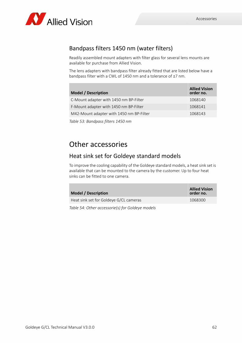
Accessories
Bandpass filters 1450 nm (water filters)
Readily assembled mount adapters with filter glass for several lens mounts are available for purchase from Allied Vision.
The lens adapters with bandpass filter already fitted that are listed below have a bandpass filter with a CWL of 1450 nm and a tolerance of ±7 nm.
Other accessories
Heat sink set for Goldeye standard models
To improve the cooling capability of the Goldeye standard models, a heat sink set is available that can be mounted to the camera by the customer. Up to four heat sinks can be fitted to one camera.
Model / DescriptionAllied Vision order no.
C‐Mount adapter with 1450 nm BP‐Filter 1068140
F‐Mount adapter with 1450 nm BP‐Filter 1068141
M42‐Mount adapter with 1450 nm BP‐Filter 1068143
Table 53: Bandpass filters 1450 nm
Model / DescriptionAllied Vision order no.
Heat sink set for Goldeye G/CL cameras 1068300
Table 54: Other accessorie(s) for Goldeye models
62Goldeye G/CL Technical Manual V3.0.0

Filters and Mounts
Goldeye G/CL Technical Manual V3.0.0
This chapter includes:
• Information about the lens mounts available for the Goldeye camera family
• Available filter options and how to change filters
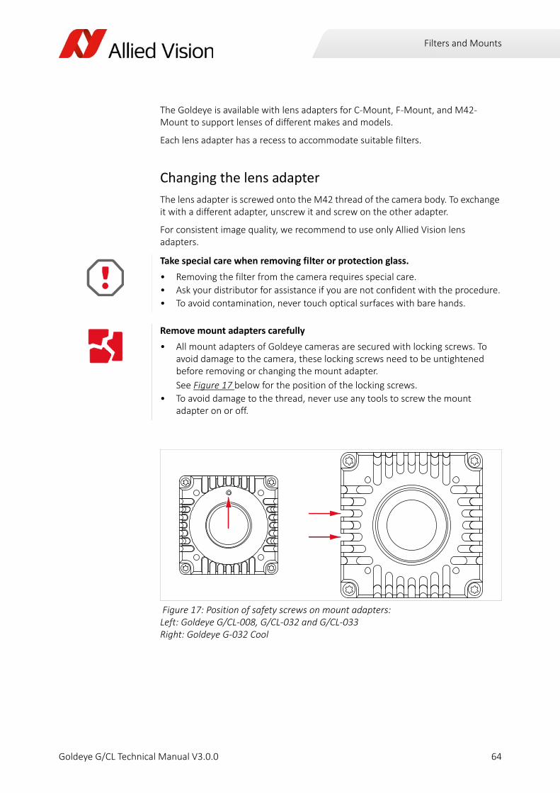
Filters and Mounts
The Goldeye is available with lens adapters for C‐Mount, F‐Mount, and M42‐Mount to support lenses of different makes and models.
Each lens adapter has a recess to accommodate suitable filters.
Changing the lens adapter
The lens adapter is screwed onto the M42 thread of the camera body. To exchange it with a different adapter, unscrew it and screw on the other adapter.
For consistent image quality, we recommend to use only Allied Vision lens adapters.
Take special care when removing filter or protection glass.
• Removing the filter from the camera requires special care.
• Ask your distributor for assistance if you are not confident with the procedure.
• To avoid contamination, never touch optical surfaces with bare hands.
Remove mount adapters carefully
• All mount adapters of Goldeye cameras are secured with locking screws. To avoid damage to the camera, these locking screws need to be untightened before removing or changing the mount adapter.
See Figure 17 below for the position of the locking screws.
• To avoid damage to the thread, never use any tools to screw the mount adapter on or off.
Figure 17: Position of safety screws on mount adapters: Left: Goldeye G/CL‐008, G/CL‐032 and G/CL‐033 Right: Goldeye G‐032 Cool
64Goldeye G/CL Technical Manual V3.0.0
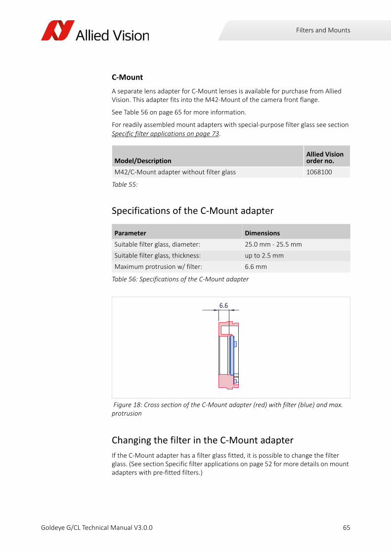
Filters and Mounts
C‐Mount
A separate lens adapter for C‐Mount lenses is available for purchase from Allied Vision. This adapter fits into the M42‐Mount of the camera front flange.
See Table 56 on page 65 for more information.
For readily assembled mount adapters with special‐purpose filter glass see section Specific filter applications on page 73.
Specifications of the C‐Mount adapter
Changing the filter in the C‐Mount adapter
If the C‐Mount adapter has a filter glass fitted, it is possible to change the filter glass. (See section Specific filter applications on page 52 for more details on mount adapters with pre‐fitted filters.)
Model/DescriptionAllied Vision order no.
M42/C‐Mount adapter without filter glass 1068100
Table 55:
Parameter Dimensions
Suitable filter glass, diameter: 25.0 mm ‐ 25.5 mm
Suitable filter glass, thickness: up to 2.5 mm
Maximum protrusion w/ filter: 6.6 mm
Table 56: Specifications of the C‐Mount adapter
Figure 18: Cross section of the C‐Mount adapter (red) with filter (blue) and max. protrusion
6.6
65Goldeye G/CL Technical Manual V3.0.0

Filters and Mounts
To change the filter of the C‐Mount lens adapter, follow the instructions outlined below.
Do not remove the adapter if a lens is mounted to the adapter. Ensure there is no lens mounted to the adapter.
Removing the adapter from the camera
1. Unscrew the adapter (1) from the camera.
‐ Loosen the locking screw (2, shown from back of adapter) on the outside of the mount adapter. See Figure 17 on page 64 for the position of the locking screws.
Use a 0.9 mm hex key for Goldeye G/CL‐008, G/CL‐032 and G/CL‐033.
Use a 1.3 mm hex key for Goldeye G‐032 Cool.
‐ To avoid penetration of foreign substances into the camera, ensure that the front flange is covered with a dust cap. See Avoiding the necessity of camera cleaning on page 118.
Removing the filter from the mount
2. On the back side of the mount, loosen the three cylinder bolts (5) of the filter fixing ring (4), using a Torx T6 tool.
3. Remove the fixing ring.
4. Remove the existing filter glass (3) from the adapter.
Installing a filter into the mount
5. Insert the new filter glass into the matching recess.
‐ See Figure 19 above (blue = filter, red = filter recess).
‐ See Table 56 above for dimensions of suitable filter glasses.
Figure 19: Changing the filter in the C‐Mount adapter
3
4
5
1
2
66Goldeye G/CL Technical Manual V3.0.0

Filters and Mounts
6. Reinsert the fixing ring into the adapter.
7. Fix the ring with the three cylinder bolts. Note there are three sets of threads to suit filter glasses of different thickness.
‐ Tighten the bolts with a max. torque of 0.25 Nm.
Attaching the mount to the camera
8. Screw the adapter into the camera.
9. Tighten the locking screw with a max. torque of 0.1 Nm.
F‐MountA separate lens adapter for F‐Mount lenses is available for purchase from Allied Vision. This adapter fits into the M42‐Mount of the camera front flange.
For readily assembled mount adapters with special‐purpose filter glass see section Specific filter applications on page 52.
(Observe for Goldeye G‐032 Cool only)
When used with the Goldeye G‐032 Cool, the mount adapter is secured by two lock‐ing screws on the side of the camera. The thread in the mount adapter needs to be closed with a thread plug to avoid light incidence.
To apply the thread plug to a C‐Mount adapter, follow the steps below.
• Push the thread plug through the locking thread, from front to back, until the end lines up with the adapters front plane.
• Cut off the excess length on the backside of the mount adapter with a sharp knife or scissors.
For more information refer to the instruction leaflet 10683004 Applying a tapered thread plug to a C‐Mount adapter.
Model/DescriptionAllied Vision order no.
M42/F‐Mount adapter without filter glass 1068101
67Goldeye G/CL Technical Manual V3.0.0

Filters and Mounts
Specifications of the F‐Mount adapter
Changing the filter in the F‐Mount adapter
If the F‐Mount adapter has a filter glass fitted, it is possible to change the filter glass. (See section Specific filter applications on page 52 for more details on mount adapters with pre‐fitted filters.)
To change the filter of the F‐Mount lens adapter, follow the instructions outlined below.
Parameter Dimensions
Suitable filter glass, diameter: 29.5 mm ‐ 30.1 mm
Suitable filter glass, thickness: 2.0 mm ‐ 2.5 mm
Maximum protrusion w/ filter: 35.1 mm
Table 57: Specifications of the F‐Mount adapter
Figure 20: Cross section of the F‐Mount adapter (red) with filter (blue) and max. protrusion
35,1
30,2Ø
40
68Goldeye G/CL Technical Manual V3.0.0

Filters and Mounts
Removing the adapter from the camera
1. Remove the lens that might be screwed into the F‐Mount adapter.
2. Unscrew the adapter (1) from the camera.
‐ Loosen the locking screw (2, shown from back of adapter) on the outside of the mount adapter. See Figure 17 on page 64 for the position of the locking screws.
Use a 0.9 mm hex key for Goldeye G/CL‐008, G/CL‐032 and G/CL‐033.
Use a 1.3 mm hex key for Goldeye G‐032 Cool.
‐ To avoid penetration of foreign substances into the camera, ensure that the front flange is covered with a dust cap. See Avoiding the necessity of camera cleaning on page 118.
Removing the filter from the mount
3. On the back side of the mount, loosen the three cylinder bolts (5) of the filter fixing ring (4), using a Torx T6 tool.
4. Remove the fixing ring.
5. Remove the existing filter glass (3) from the adapter.
Installing a filter into the mount
6. Insert the new filter glass into the matching recess.
‐ See Table 21 above (blue = filter, red = filter recess).
‐ See Table 57 above for dimensions of suitable filter glasses.
7. Insert the fixing ring into the adapter.
8. Fix the ring with the three cylinder bolts.
‐ Tighten the bolts with a max. torque of 0.25 Nm.
Figure 21: Changing the filter in the F‐Mount adapter
1
23
45
69Goldeye G/CL Technical Manual V3.0.0

Filters and Mounts
Attaching the mount to the camera
9. Screw the adapter into the camera again.
10. Tighten the locking screw with a max. torque of 0.1 Nm.
M42‐MountTo avoid scratching or other damages to filter glasses, always store away unused filter glasses carefully.
Specifications of the M42‐Mount adapter
Never use the camera without a mount adapter.
To avoid damaging the sensor or sensor board, never try to screw a lens directly into the M42‐Mount of the camera front flange. Always use the M42‐Mount adapter when working with M42‐lenses.
Parameter Dimensions
Suitable filter glass, diameter: 29.5 mm ‐ 30.1 mm
Suitable filter glass, thickness: 2.0 mm ‐ 2.5 mm
Maximum protrusion w/ filter: 34 mm / 35.8 mm
Table 58: Specifications of the M42‐Mount adapter
Figure 22: Cross section of the M42‐Mount adapter (red) with filter (blue) and max. protrusion
35,834
70Goldeye G/CL Technical Manual V3.0.0

Filters and Mounts
Changing the filter in the M42‐Mount adapter
If the M42‐Mount adapter has a filter glass fitted, it is possible to change the filter glass. (See section Specific filter applications on page 52 for more details on mount adapters with pre‐fitted filters.)
To change the filter of the M42‐Mount lens adapter, follow the instructions outlined below.
Removing the adapter from the camera
1. Remove the lens that might be screwed into the M42‐Mount adapter.
2. Unscrew the adapter (1) from the camera.
‐ Loosen the locking screw (2, shown from back of adapter) on the outside of the mount adapter. See Figure 17 on page 64 for the position of the locking screws.
Use a 0.9 mm hex key for Goldeye G/CL‐008, G/CL‐032 and G/CL‐033.
Use a 1.3 mm hex key for Goldeye G‐032 Cool.
‐ To avoid penetration of foreign substances into the camera, ensure that the front flange is covered with a dust cap. See Avoiding the necessity of camera cleaning on page 118.
Removing the filter from the mount
3. On the back side of the mount, loosen the three cylinder bolts (5) of the filter fixing ring (4), using a Torx T6 tool.
4. Remove the fixing ring.
5. Remove the existing filter glass (3) from the adapter.
Installing a filter into the mount
6. Insert the new filter glass into the matching recess.
Figure 23: Changing the filter in the M42‐Mount adapter
2
3
45
1
71Goldeye G/CL Technical Manual V3.0.0

Filters and Mounts
‐ See Figure 23 (blue = filter, red = filter recess).
‐ See Table 58 above for dimensions of suitable filter glasses.
7. Insert the fixing ring into the adapter.
8. Fix the ring with the three cylinder bolts.
‐ Tighten the bolts with a max. torque of 0.25 Nm.
Attaching the mount to the camera
9. Screw the adapter into the camera.
10. Tighten the locking screw with a max. torque of 0.1 Nm.
72Goldeye G/CL Technical Manual V3.0.0
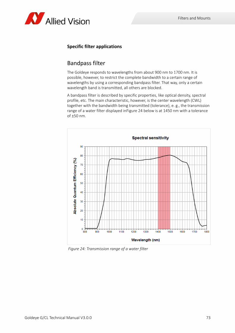
Filters and Mounts
Specific filter applications
Bandpass filter
The Goldeye responds to wavelengths from about 900 nm to 1700 nm. It is possible, however, to restrict the complete bandwidth to a certain range of wavelengths by using a corresponding bandpass filter. That way, only a certain wavelength band is transmitted, all others are blocked.
A bandpass filter is described by specific properties, like optical density, spectral profile, etc. The main characteristic, however, is the center wavelength (CWL) together with the bandwidth being transmitted (tolerance), e. g., the transmission range of a water filter displayed inFigure 24 below is at 1450 nm with a tolerance of ±50 nm.
Figure 24: Transmission range of a water filter
73Goldeye G/CL Technical Manual V3.0.0
Filters and Mounts
Bandpass filters 1450 nm (water filters)
Readily assembled mount adapters with filter glass for several lens mounts are available for purchase from Allied Vision.
The lens adapters with bandpass filter already fitted that are listed below have a bandpass filter with a CWL of 1450 nm and a tolerance of ±7 nm.
Avoid damage to filter glasses
To avoid scratching or other damages to filter glasses, always store away unused fil‐ter glasses carefully.
Model / DescriptionAllied Vision order no.
C‐Mount adapter with 1450 nm BP‐Filter 1068140
F‐Mount adapter with 1450 nm BP‐Filter 1068141
M42‐Mount adapter with 1450 nm BP‐Filter 1068143
Table 59: Bandpass Filters 1450 nm
74Goldeye G/CL Technical Manual V3.0.0

Camera interfaces
Goldeye G/CL Technical Manual V3.0.0
This chapter includes:
• A general description of the inputs and outputs of the cameras
‐ Gigabit Ethernet port
‐ Camera Link port
• I/O connector pin assignments
• Schematic input/output block diagrams
• A general description of trigger features and rules such as timing diagram and definitions.

Camera interfaces
Warning:Observe safety when using electrical connections.
For connections to any power outlet, only use connectors that fit, and/or adapters with a grounding lead.
Use sufficient grounding to minimize the risk of damage.
Overview of GigE anf Camera Link accessories
Allied Vision provides accessories to run and connect the Goldeye camera. To obtain an overview of all accessories available, go to the Allied Vision Accessories website:
http://www.alliedvision.com/en/support/technical‐documentation/accessories‐datasheets.html
i
76Goldeye G/CL Technical Manual V3.0.0

Camera interfaces
Power supplyThere is a distinctive difference in power supply options between different Goldeye camera models.
All Goldeye models do not work in reverse polarity.
Goldeye G only: Power supply via Gigabit Ethernet
You can supply Goldeye G models with power through the Gigabit Ethernet port by using any standard Power over Ethernet (PoE or PoE+) supported network connection.
The pin assignment of the RJ45/8P8C connector is according to the Ethernet Standard (IEEE 802.3 1000BASE‐T), which supports cable lengths of up to 100 m. All Goldeye G can obtain power from 802.3af/at compliant PSE devices (Power Sourcing Equipment): such as switches, injectors, or NICs.
If the Hirose connector provides a valid DC voltage to the camera, and the GigE connector is connected via PoE at the same time, the camera obtains power from the Hirose connector only.
Goldeye models Hirose PoE
G‐008, G‐032, G‐033
Through the Hirose I/O port, via Pin 1, External GND, and Pin 2, External Power.
Through the Gigabit Ethernet port by a PoE (802.3af/at) supported network card, switch, or injector.
G‐032 Cool Through the Hirose 4‐pin power port, not using Pin 2, External Power, of the HiroseI/O port.
Through the Gigabit Ethernet port by a PoE+ (802.3at) supported network card, switch, or injector.
CL‐008, CL‐032, CL‐033
Through the Hirose I/O port, via Pin 1, External GND, and Pin 2, External Power.
‐‐‐
Table 60: Differences in power supply between different Goldeye models.
Goldeye G models: Minimizing Power consumption
If the camera operates under higher temperature conditions, it should be consid‐ered to power the camera via the I/O connector instead of PoE, since PoE contrib‐utes to the heat build‐up inside the camera.
Refer to chapter Technical Data on page 22 for details on power consumption.
77Goldeye G/CL Technical Manual V3.0.0

Camera interfaces
Power supply via Hirose connector
Provide power to the Goldeye G/CL by the I/O port:
• either using a power adapter with Hirose 12‐pin connector,
• or using an I/O cable with Hirose 12‐pin connector in conjunction with a stan‐dard power supply adapter.
Provide power to a Goldeye G‐032 Cool by the power port:
• either using a power adapter with Hirose 4‐pin connector,
• or using a power cable with Hirose 4‐pin connector in conjunction with a stan‐dard power supply adapter.
• You cannot use the Hirose 12‐pin I/O connector to supply the Goldeye G‐032 Cool with power.
Quick overview: Power adapters and connectors
12‐pin Hirose connector
The cable side Hirose connector (without cable) and I/O cables with Hirose connector are available for purchase from Allied Vision.
Ensure an adequate power supply
In case the camera is provided with power via the I/O connector, always ensure that the voltage at the camera input lies within the designated requirement of 10.8 V to 30.0 V.
Model/Description Allied Vision order no.
Hirose 12‐pin connector w/o cable K7600040
I/O cable w/ Hirose 12‐pin connector, 2 m 2814
I/O cable w/ Hirose 12‐pin connector, 3 m 2815
I/O cable w/ Hirose 12‐pin connector, 5 m 2817
I/O cable w/ Hirose 12‐pin connector, 10 m 2818
Table 61: Available 12‐pin Hirose connectors and cables (excerpt only)
78Goldeye G/CL Technical Manual V3.0.0

Camera interfaces
Power adapter for Goldeye G/CL models
A 12 V power adapter with Hirose connector is available for purchase from Allied Vision.
Power adapter for Goldeye G Cool
A 12 V power adapter with Hirose connector is available for purchase from Allied Vision (for Goldeye G Cool only):
Model/Description Allied Vision order no.
North American supply, 12 V / 1.25 A:Desktop power supply 12‐pin Hirose female plug, US plug
02‐8003D
European supply:Desktop power supply 12‐pin Hirose female plug, EURO plug
02‐8004D
Power supply, 12 V DC, 15 W, standard E3100002
Table 62: Available 12 V power adapters (excerpt only).
Model/Description Allied Vision order no.
North American and European supply, 12 V / 5 A:Desktop power supply 4‐pin Hirose female plug
1021080
Table 63: Available power adapter for Goldeye G Cool
79Goldeye G/CL Technical Manual V3.0.0

Camera interfaces
Gigabit Ethernet Goldeye G cameras are equipped with a Gigabit Ethernet interface.
GigE GigE is the abbreviation for Gigabit Ethernet.
All Allied Vision Goldeye G cameras are GigE Vision compliant cameras with Gigabit Ethernet interface. Allied Vision Goldeye G cameras work with standard Gigabit Ethernet hardware and cables, and serve cable lengths up to 100 m.
GigE Vision The GigE Vision standard is an interface standard for digital machine vision cam‐eras, developed and maintained by the Automated Imaging Association (AIA). It is built on the Gigabit Ethernet communication protocol and widely supported in the industrial imaging industry.
GenICam GenICam is the command structure for the GigE Vision camera control. GenICam is administered by the European Machine Vision Association (EMVA).
GenICam establishes a common camera control interface so that third‐party soft‐ware can communicate with cameras from various manufacturers without customization. It is incorporated as part of the GigE Vision standard.
Gigabit Ethernet port The Gigabit Ethernet port conforms to the 1000BASE‐T standard for Gigabit Ethernet. We recommend using Cat 5e compatible cabling and connectors or better for best performance.
The back panel
Figure 25: Connection ports and LEDs of a Goldeye G‐008, G‐032, G‐033
TemperatureStatus LED
I/O Port:Camera power
External Sync IORS-232 TX/RX
GigE cable
GigE
GigE
80Goldeye G/CL Technical Manual V3.0.0

Camera interfaces
The Goldeye G has the following LEDs on its rear panel:
• Two LEDs at the RJ45/8P8C port showing the GigE connection status.
• One temperature status LED showing the sensor and camera temperature sta‐tus. See Temperature control of the sensor on page 110 for further explanation.
GigE status LEDs
Figure 26: Connection ports and LEDs of a Goldeye G‐032 Cool
Read more about temperature management
For detailed explanations on temperature status and temperature management of the Goldeye G/CL, refer to chapter Temperature control on page 109.
LED # LED color Status
LED 1 Ethernet activity
Amber (cont.or flashing)
LED 2 Camera is connected to power
Green (flash.)
LED 2 Camera is booted, link with the host is established
Green (cont.)
Table 64: Goldeye G: GigE status LEDs.
Gigabit Ethernet Port
GigE
GigE
Temperature
GigE cable
I/O Port:External Sync IO
Power port:Camera power
81Goldeye G/CL Technical Manual V3.0.0
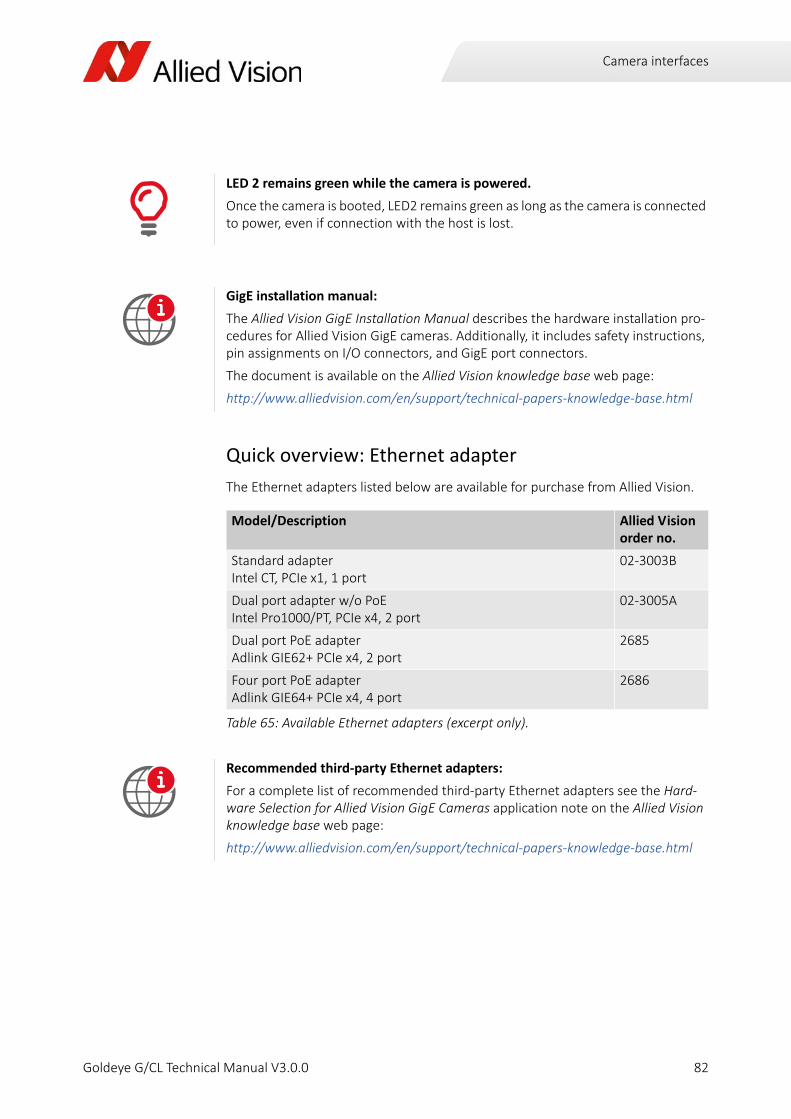
Camera interfaces
Quick overview: Ethernet adapter
The Ethernet adapters listed below are available for purchase from Allied Vision.
LED 2 remains green while the camera is powered.
Once the camera is booted, LED2 remains green as long as the camera is connected to power, even if connection with the host is lost.
GigE installation manual:
The Allied Vision GigE Installation Manual describes the hardware installation pro‐cedures for Allied Vision GigE cameras. Additionally, it includes safety instructions, pin assignments on I/O connectors, and GigE port connectors.
The document is available on the Allied Vision knowledge base web page:
http://www.alliedvision.com/en/support/technical‐papers‐knowledge‐base.html
Model/Description Allied Vision order no.
Standard adapterIntel CT, PCIe x1, 1 port
02‐3003B
Dual port adapter w/o PoEIntel Pro1000/PT, PCIe x4, 2 port
02‐3005A
Dual port PoE adapterAdlink GIE62+ PCIe x4, 2 port
2685
Four port PoE adapterAdlink GIE64+ PCIe x4, 4 port
2686
Table 65: Available Ethernet adapters (excerpt only).
Recommended third‐party Ethernet adapters:
For a complete list of recommended third‐party Ethernet adapters see the Hard‐ware Selection for Allied Vision GigE Cameras application note on the Allied Vision knowledge base web page:
http://www.alliedvision.com/en/support/technical‐papers‐knowledge‐base.html
i
i
82Goldeye G/CL Technical Manual V3.0.0
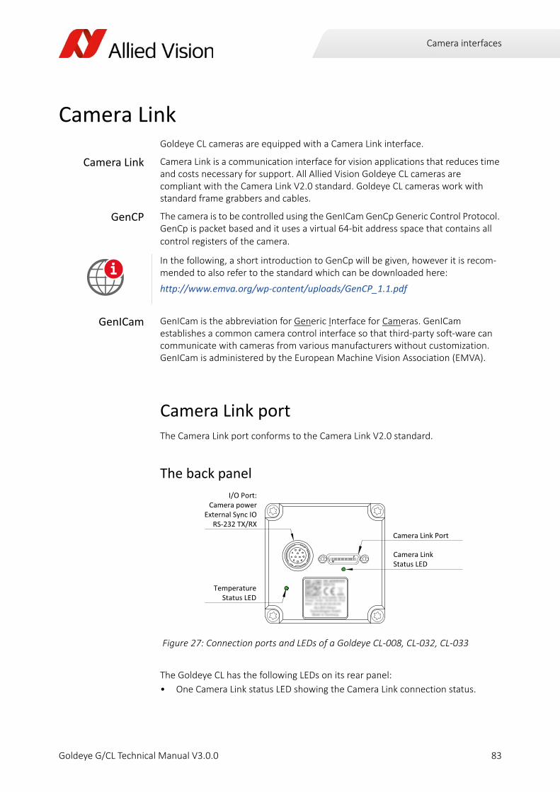
Camera interfaces
Camera LinkGoldeye CL cameras are equipped with a Camera Link interface.
Camera Link Camera Link is a communication interface for vision applications that reduces time and costs necessary for support. All Allied Vision Goldeye CL cameras are compliant with the Camera Link V2.0 standard. Goldeye CL cameras work with standard frame grabbers and cables.
GenCP The camera is to be controlled using the GenICam GenCp Generic Control Protocol. GenCp is packet based and it uses a virtual 64‐bit address space that contains all control registers of the camera.
GenICam GenICam is the abbreviation for Generic Interface for Cameras. GenICam establishes a common camera control interface so that third‐party soft‐ware can communicate with cameras from various manufacturers without customization. GenICam is administered by the European Machine Vision Association (EMVA).
Camera Link portThe Camera Link port conforms to the Camera Link V2.0 standard.
The back panel
The Goldeye CL has the following LEDs on its rear panel:
• One Camera Link status LED showing the Camera Link connection status.
In the following, a short introduction to GenCp will be given, however it is recom‐mended to also refer to the standard which can be downloaded here:
http://www.emva.org/wp‐content/uploads/GenCP_1.1.pdf
Figure 27: Connection ports and LEDs of a Goldeye CL‐008, CL‐032, CL‐033
i
TemperatureStatus LED
I/O Port:Camera power
External Sync IORS-232 TX/RX
Camera LinkStatus LED
Camera Link Port
83Goldeye G/CL Technical Manual V3.0.0

Camera interfaces
• One temperature status LED showing the sensor and camera temperature sta‐tus. See Temperature control of the sensor on page 110 for further explanation.
Camera Link Status LED
Frame grabber requirementsYou can use basically any Camera Link Base compatible frame grabber to operate Goldeye CL cameras. However, following general aspects should be considered for frame grabber selection:
• The frame grabber needs to support the individual pixel clock frequency of the camera (which may be up to 85 MHz, depending on the model).
• The frame grabber and the host system need to support the pixel data band‐width delivered by the camera.
Depending on model and operation mode, a Camera Link Base camera may be able to output up to approx. 170 million 12‐bit pixels per second. Assuming a worst‐case scenario of unpacked 16 bits per pixel transfer over the host bus, this results in 340 million bytes per second. This is approximately three times the bandwidth of a Gigabit Ethernet port.
• Host software design and system architecture usually affect frame grabber selection as well, for instance the number of cameras connected to the host, the different types of cameras connected, or the availability of a frame grabber specific GenICam transport layer.
Read more about temperature management
For detailed explanations on temperature status and temperature management of the Goldeye G/CL, refer to chapter Temperature control on page 109.
LED color and flashing pattern
StatusDescription
Booting
After powering up the camera, it indicates the boot phase with a periodic green‐red flashing.
A firmware update in progress is indicated the same way.
Green‐red (1 Hz periodic flashing)
Idle
A steady green light indicates that the camera is idle and ready.
Green (continuous)
Transmission
During transmission of image data the LED toggles between red and green. Traffic on the serial control channel is shown by additional irregular fast green‐red flashing. This may cause the LED to appear amber colored.
Green‐red (non‐periodic fast flashing)
84Goldeye G/CL Technical Manual V3.0.0

Camera interfaces
• A high baudrate support (> 115 200 baud) of the Camera Link serial port is rec‐ommended to improve responsivity of host software.
More information about frame grabbers:
For more information about compatibility of various frame grabber models and sys‐tem installation refer to the Goldeye CL Installation Guide, downloadable from the Allied Vision website:
http://www.alliedvision.com/en/support/technical‐papers‐knowledge‐base.html
Technical information and support:
To receive advice on suitable frame grabbers for your application, contact the Allied Vision support team.
i
85Goldeye G/CL Technical Manual V3.0.0

Camera interfaces
I/O connectors and pin assignment
Connectors
I/O types
Non‐isolated I/Os:
• One non‐isolated line‐in (3.3 V LVTTL, 5 V TTL tolerated, see Table 68 on page 87 )
• One non‐isolated line‐out (5 V TTL)
Opto‐isolated I/Os:
• One opto‐isolated line‐in
• Two opto‐isolated line‐out
• Maximum isolated power voltage is 30 V
• Line‐in voltages:
• Vin(low) = 0.0 V to 1.0 V
• Vin(high) = 3.0 V to 24.0 V
Caution:Avoid electrostatic discharge.
Electrostatic sensitive device.
To prevent equipment damage, use proper grounding techniques.
Avoid electromagnetic interferences.
For all power and interface connections use only shielded cables.
Camera Connectors Usage
Goldeye G‐008, CL‐008 Hirose 12‐pin External power and I/O
Goldeye G‐032, CL‐032 Hirose 12‐pin External power and I/O
Goldeye G‐032 Cool Hirose 12‐pin
Hirose 4‐pin
I/O
External power
Goldeye G‐033, CL‐033 Hirose 12‐pin External power and I/O
Table 66: Hirose connectors used with Goldeye cameras
86Goldeye G/CL Technical Manual V3.0.0

Camera interfaces
Quick overview: trigger cables with 12‐pin Hirose connector
The cable side Hirose connector (without cable) and I/O cables with Hirose connector are available for purchase from Allied Vision (excerpt only):
Pin assignment
Model/Description Allied Vision order no.
Trigger cable In1 BNC LVTTL w/ Hirose 12‐pin connector, 2 m 1068908
Trigger cable In1 BNC LVTTL w/ Hirose 12‐pin connector, 5 m 1068909
Table 67: Available trigger cables with Hirose 12‐pin connector
Pin Signal I/O Level Description
1 External GND
In/ Out
GND for RS‐232 and external power
Ext. ground for RS‐232, TTL I/Os (and ext. power)
2 External Power
In 10.8 V to 30.0 V DC Power supply
For Goldeye G‐032 Cool only: Pin 2 is not connected.
3 Video Type Auto Iris Out
Out ‐‐‐ Video iris
4 In 1 In Vin (low) 0.0 V to 0.8 V
Vin (high) 2.0 V to 5.0 V
Input 1non‐isolated (SyncIn1)
5 Out 3 Out Open emitter, max. 20 mA
Output 3 opto‐isolated (SyncOut3)
6 Out 1 Out TTL (5 V, max. 20 mA) Output 1 non‐isolated (SyncOut1)
7 Isolated In GND
In Common GND for opto‐isolated inputs
Camera common input ground (In GND)
8 RxD RS‐232 In RS‐232 Terminal receive data
9 TxD RS‐232 Out RS‐232 Terminal transmit data
10 Isolated Out Power
In Common supply voltage for outputs max. 30 V DC
External power input for digital outputs (Out VCC)
11 In 2 In Vin (low) 0.0 V to 1.0 V
Vin (high) 3.0 V to 24.0 V
Input 2opto‐isolated (SyncIn2)
12 Out 2 Out Open emitter,max. 20 mA
Output 2 opto‐isolated (SyncOut2)
Table 68: I/O connector pin assignment for all Goldeye cameras
2
654113
107
891
12
87Goldeye G/CL Technical Manual V3.0.0

Camera interfaces
I/O definitionExplanation of I/O Definitions
External GND and external power (pin 1, pin 2)
For G/CL‐008, G/CL‐032 and G/CL‐033: Use pin 1 and pin 2 to supply the camera with power.
For G‐032 Cool: Use the Hirose four‐pin connector to supply the camera with power.
For more information on power supply refer to section section Power Supply on page 57.
RxD RS‐232 and TxD RS‐232 (pin 8, pin 9)
These signals are RS‐232 compatible. These signals are not optically isolated. Connect RS‐232 ground to Camera GND to complete the RS‐232 circuit. Communication takes place at a bandwidth of 115,200 baud (customer adjustable).
Pin Signal I/O Level Description
1 External Power
In 10.8 V to 30.0 V DC External power
2 External Power
In 10.8 V to 30.0 V DC External power
3 External GND
In GND external power Ext. ground for ext. power
4 External GND
In GND external power Ext. ground for ext. power
Table 69: Goldeye G‐032 Cool power connector pin assignment
Observe the input voltage.
Exceeding the 30 V input voltage can permanently damage the camera.
More information on the RS‐232 interface:
For complete RS‐232 description and usage on GigE cameras, see the application note RS‐232 Port Explained on the Allied Vision Knowledge base web page:
http://www.alliedvision.com/en/support/technical‐papers‐knowledge‐base.html
12 3
4
i
88Goldeye G/CL Technical Manual V3.0.0

Camera interfaces
Isolated out power (pin 10)
The Isolated Out Power must be connected to a power source for isolated signals Out 2 and Out 3. The voltage requirement is 3 to 30 V DC. The current requirement for this supply is a function of the optical insulator collector current and the number of outputs used in the system. Isolated Out Power wiring should be physically close to Out 2 / Out 3 wiring to prevent parasitic coupling.
Input signalsInput signals allow the camera to be synchronized to an external event. The camera can be programmed to trigger on the rising edge, falling edge, both edges, or level of the signal. The camera can also be programmed to capture an image at some programmable delay time after the trigger event.
In 1 ‐ non‐isolated (pin 4)
In 1 is not electrically isolated and can be used when environmental noise is inconsequential, and a faster trigger response is required. To complete the trigger circuit, connect trigger ground to External GND.
In 2 ‐ opto‐isolated (pin 11)
In 2 is optically isolated and can be used in electrically noisy environments to prevent false trigger events. To complete the trigger circuit, connect trigger ground to Isolated In GND. Compared to the non‐isolated trigger, In 2 has a longer propagation time.
Trigger signal Input current
Required trigger signal: LVTTL (3.3 V), TTL (5 V) tolerated
Input current to be expected in TTL mode: 3 mA
Input current to be expected in LVTTL mode: 0.3 mA
Table 70: Input 1 ‐ trigger signal and input current
Trigger signal Input current
Trigger input voltage: Vin (low): 0.0 V to 1.0 V
Trigger input voltage: Vin (high): 3.0 V to 24.0 V
Input current to be expected: 5 mA
Table 71: Input 2 ‐ trigger signal and input current
89Goldeye G/CL Technical Manual V3.0.0

Camera interfaces
Isolated input block diagram
The inputs can be connected directly to the system for voltages up to 24 V DC. An external resistor is not necessary.
Goldeye G/CL isolated input delay and minimum pulse width
The minimum pulse width for all Goldeye G/CL cameras is:
Test conditions
The input signal was driven with 3.3 V (LVTTL) and no external additional series resistor was used.
Output signalsOutput signals can be assigned to a variety of internal camera signals via software. They can be configured to active high or active low. The internal camera signals are listed in Table 76, Goldeye G/CL output signals, on page 94 .
Figure 28: Goldeye G/CL isolated input block diagram
Figure 29: Goldeye G/CL minimum pulse width
Output signal Description
Exposing Indicates when camera is integrating light.
Trigger Ready Indicates when the camera is ready to accept a trigger signal.
Figure 30: Internal camera signals available in the Goldeye G/CL
InGND
External Internal
GPIn2
IF
0t
44 μs
6 μs 20 kHz
90Goldeye G/CL Technical Manual V3.0.0

Camera interfaces
Out 1 ‐ non‐isolated (pin 6)
The Out 1 signal is not electrically isolated and can be used when environmental electrical noise is inconsequential, and faster trigger response is required. Connect signal ground to External GND to complete the external circuit.
Out 2 (pin 12) and Out 3 (pin 5) ‐ opto‐isolated
Out 2 and Out 3 signals are optically isolated and require the user to provide a voltage level at Isolated Out Power.
An example of the functional circuit is indicated in Figure 31, „Goldeye G/CL isolated output block diagram,“ on page 92.
Trigger Input A relay of the trigger input signal used to “daisy chain” the trigger signal for multiple cameras.
Readout Valid when the camera is reading out data.
Imaging Valid when the camera is exposing or reading out.
Strobe Programmable pulse based on one of the above events.
GPO User programmable binary output.
Signal Output
Output signal TTL (5 V)
Maximum output current 20 mA
Table 72: Output 1 output signal and maximum current
Possible low output voltage
Output voltage may drop down to 3.5 V under full load.
Signal Output
Possible voltage source OutVCC Range 3 V to 30 V
Maximum output current per output 20 mA
Table 73: Output 2 / Output 3 voltage source and current per channel
Output signal Description
Figure 30: Internal camera signals available in the Goldeye G/CL (continued)
91Goldeye G/CL Technical Manual V3.0.0
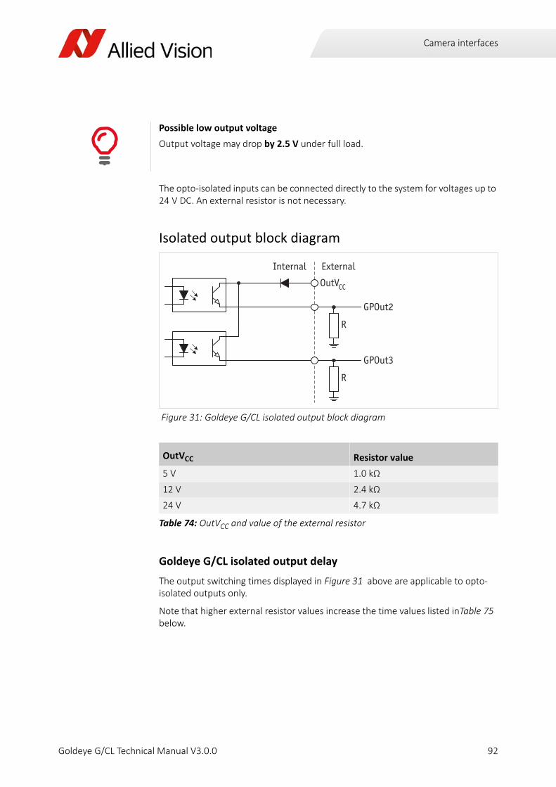
Camera interfaces
The opto‐isolated inputs can be connected directly to the system for voltages up to 24 V DC. An external resistor is not necessary.
Isolated output block diagram
Goldeye G/CL isolated output delay
The output switching times displayed in Figure 31 above are applicable to opto‐isolated outputs only.
Note that higher external resistor values increase the time values listed inTable 75 below.
Possible low output voltage
Output voltage may drop by 2.5 V under full load.
Figure 31: Goldeye G/CL isolated output block diagram
OutVCC Resistor value
5 V 1.0 kΩ
12 V 2.4 kΩ
24 V 4.7 kΩ
Table 74: OutVCC and value of the external resistor
ExternalInternal
OutV
GPOut2
GPOut3
R
R
CC
92Goldeye G/CL Technical Manual V3.0.0
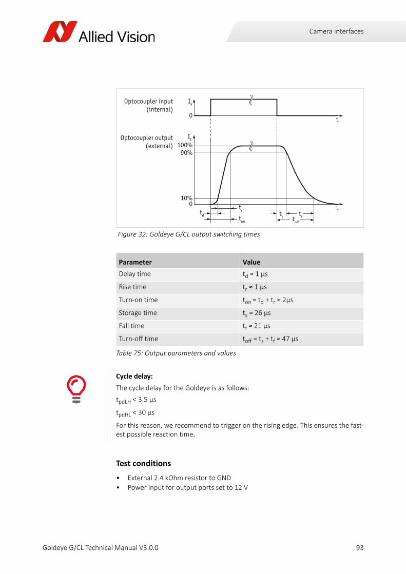
Camera interfaces
Test conditions
• External 2.4 kOhm resistor to GND
• Power input for output ports set to 12 V
Figure 32: Goldeye G/CL output switching times
Parameter Value
Delay time td ≈ 1 μs
Rise time tr ≈ 1 µs
Turn‐on time ton = td + tr ≈ 2µs
Storage time ts ≈ 26 µs
Fall time tf ≈ 21 µs
Turn‐off time toff = ts + tf ≈ 47 µs
Table 75: Output parameters and values
Cycle delay:
The cycle delay for the Goldeye is as follows:
tpdLH < 3.5 µs
tpdHL < 30 µs
For this reason, we recommend to trigger on the rising edge. This ensures the fast‐est possible reaction time.
IF
0
IC
100%90%
10%
t
t0
Optocoupler input(internal)
Optocoupler output(external)
td ton
trts tftoff
93Goldeye G/CL Technical Manual V3.0.0

Camera interfaces
Control signals
The inputs and outputs of the camera can be configured by software. The different modes are described below.
Inputs
Input / output pin control
Outputs
Output features are configured by software. Any signal can be placed on any output. .
More details on outputs and warnings:
For a general description of the outputs and warnings see the Allied Vision GigE Installation Manual in the Allied Vision Literature Download Center:
http://www.alliedvision.com/en/support/technical‐papers‐knowledge‐base.html
Figure 33: Goldeye G/CL input signal block diagram
More details on input and output signals:
All input and output signals running over the camera I/O connector are controlled by the I/O strobe commands. For more details see the Allied Vision Goldeye G/CL Features Reference in the Allied Vision Knowledge Base web page:
http://www.alliedvision.com/en/support/technical‐papers‐knowledge‐base.html
Signal Description
GPO Configured to be a general purpose output, control of which is assigned to SyncOutGpoLevels.
AcquisitionTriggerReady Active once the camera has been recognized by the host PC and is ready to start acquisition.
Table 76: Goldeye G/CL output signals
i
i
94Goldeye G/CL Technical Manual V3.0.0

Camera interfaces
FrameTriggerReady Active when the camera is in a state that accepts the next frame trigger.
FrameTrigger Active when an image has been initiated to start. This is a camera‐internal logic trigger, which is initiated by an external trigger or software trigger event.
Exposing Active for the duration of sensor exposure.
FrameReadout Active during frame readout, i.e., the transferring of image data from the CCD to camera memory.
Imaging High when the camera image sensor is either exposing and/or reading out data.
Acquiring Active during an acquisition stream.
SyncIn1 Active when there is an external trigger at SyncIn1.
SyncIn2 Active when there is an external trigger at SyncIn2.
Strobe1 The output signal is controlled according to Strobe1 settings.
Figure 34: Goldeye G/CL signals output block diagram
Signal Description
Table 76: Goldeye G/CL output signals (continued)
95Goldeye G/CL Technical Manual V3.0.0

Camera interfaces
Trigger timing diagram
The diagram below explains the trigger concept in general.
Notes on triggering
Trigger definitions
Figure 35: Goldeye G/CL trigger timing diagram
Trigger description for GigE cameras
For trigger descriptions on camera control basis see the Allied Vision GigE Camera and Driver Features document in the Allied Vision knowledge base web page:
http://www.alliedvision.com/en/support/technical‐papers‐knowledge‐base.html
Term Definition
User trigger Trigger signal applied by the user (hardware trigger, software trigger).
Logic trigger Trigger signal seen by the camera internal logic (not visible to the user).
Tpd Propagation delay between the User trigger and the Logic trigger.
Exposure High when the camera image sensor is integrating light.
Readout High when the camera image sensor is reading out data.
Trigger latency Time delay between the user trigger and the start of exposure.
Table 77: Goldeye G/CL trigger definitions
i
96Goldeye G/CL Technical Manual V3.0.0

Camera interfaces
Trigger rules
1. The end of exposure always triggers the next Readout.
2. The end of exposure must always end after the current Readout.
3. The start of exposure must always correspond with the Interline Time if Read‐out is true.
4. Exposure start delay is equal to the Readout time less the Registered Exposure Time.
Triggering during the Idle state
For applications requiring the shortest possible trigger latency and the smallest possible trigger jitter the User trigger signal should be applied when Imaging is false and Idle is true. In this case, trigger latency and trigger jitter can be up to 1 line time.
Triggering during the readout state
For applications requiring the fastest triggering cycle time during which the camera image sensor is exposing and reading out simultaneously, then the User trigger
Trigger jitter Error in the trigger latency time.
Trigger ready Indicates to the user that the camera is ready to accept the next trigger.
Registered exposure time
Exposure time value currently stored in the camera memory.
Exposure start delay Registered Exposure Time subtracted from the Readout time. Exposure start delay indicates when the next exposure cycle can begin such that the exposure end after the current Readout.
Interline time Time between sensor row readout cycles.
Imaging High when the camera image sensor is either exposing and/or reading out data.
Idle High if the camera image sensor is not exposing and/or reading out data.
Minimum user trigger pulse width
The user trigger pulse width should be at least three times the width of the trigger latency.
Term Definition
Table 77: Goldeye G/CL trigger definitions (continued)
97Goldeye G/CL Technical Manual V3.0.0

Camera interfaces
signal should be applied as soon as a valid trigger Ready is detected. In this case, trigger latency and trigger jitter can be up to 1 line time.
Triggering concept for GigE camera (advanced):
For a more detailed description of the trigger concept for advanced users and spe‐cial scenarios, see the application note Triggering Concept for Allied Vision GigE Cameras in the Allied Vision knowledge base web page:
http://www.alliedvision.com/en/support/technical‐papers‐knowledge‐base.html
i
98Goldeye G/CL Technical Manual V3.0.0

Data processing path
Goldeye G/CL Technical Manual V3.0.0
This chapter includes:
• Description of the data processing path of the Goldeye G/CL cameras in block diagrams
• Explanation of the IR‐specific image processing features of the Goldeye G/CL firmware
• Listing of all camera control features of the Goldeye G/CL

Data processing path
Image processing chainThe block diagrams below illustrate the data flow of image data within the camera. The features of the individual modules are described in more detail on the following pages.
Note that, depending on firmware version, not all of the modules and features shown below are available.
Figure 36: Goldeye G image processing chain
Analog Analog
14 bit
14 bit
14 bit
GigE
14 bit14 bit 14 bit
DPCDPC
++++++ +++
+ +
+++
+ +
+++++++++++++++++++++++++++++
++++++++++++++++++++++++++++
++++++++++++++
14 bit
14 bit 14 bit 14 bit
Camera Control
Camera Control
Correc on Data Pipeline
HiroseI/O
I / O
Sensor Analog Gain ADC
NUCBackground Corr.
+
-
Binning Horiz.
Binning Ver cal Digital Gain Gamma LUT
Frame MemoryGigE Interface
Correc on Data
Memory
100Goldeye G/CL Technical Manual V3.0.0

Data processing path
The Goldeye G/CL contains a chain of image processing modules, called the image processing chain. The first module (called Analog Gain) receives the source signal
Figure 37: Goldeye CL image processing chain
GigE features and Camera Link registers:
Find a complete description of features and registers in the Allied Vision Goldeye G/CL Features Reference document. It describes the standard and advanced camera controls for Allied Vision Goldeye G and CL cameras as seen from the Allied Vision Vimba Viewer.
To access the document, go to the Technical Documentation web page and click on the Goldeye camera:
http://www.alliedvision.com/en/support/technical‐documentation.html
Analog Analog
14 bit
14 bit
14 bit
Camera
Link
14 bit14 bit 14 bit
DPCDPC
++++++ +++
+ +
+++
+ +
+++++++++++++++++++++++++++++
++++++++++++++++++++++++++++
++++++++++++++
14 bit
14 bit 14 bit 14 bit
Camera Control
Camera Control
Correc on Data Pipeline
HiroseI/O
I / O
Sensor Analog Gain ADC
NUCBackground Corr.
+
-
Binning Horiz.
Binning Ver cal Digital Gain Gamma LUT
Frame MemoryCL Interface
Correc on Data
Memory
i
101Goldeye G/CL Technical Manual V3.0.0

Data processing path
from the sensor. Each of the subsequent modules receives the output data of the previous module as input.
The behavior of each module is configurable by software via specific features. That way, it is possible to set parameters or operation modes for each module.
Each module passes on the data to the succeeding module. The output of the last module is stored in the frame memory, which in turn passes it on to the GigE or Camera Link interface for output.
102Goldeye G/CL Technical Manual V3.0.0

Data processing path
Image corrections for SWIR sensorsThe corrections applied to the image are of special relevance within the Goldeye camera. They are applied by the following modules.
• Non‐uniformity correction (NUC)
• Background correction (BC)
• Defect pixel correction (DPC)
The corrections need special correction data that must be provided prior to operating the image processing chain.
Determination and storage of correction data
For each individual camera, specific correction data is determined during the manufacturing process. All necessary correction data is stored within the camera‘s non‐volatile flash memory ex works.
During camera start‐up, the available correction data is copied from the flash memory onto the correction data memory for real time access.
From the correction data memory, the correction data is transferred to the individual correction modules. The correction data transfer is synchronized with the transfer of image data from the sensor. A correction module may also write back to the correction data memory, depending on its functionality.
The IR specific image correction modules are described in detail below.
Non‐uniformity correction (NUC)Every pixel of an InGaAs sensor possesses its individual amount of dark signal (dark signal non‐uniformity, DSNU) and an individual sensitivity for light (photo response non‐uniformity, PRNU). Thus, while exposing, each sensor creates a specific, non‐uniform underlying pattern. This pattern can be compensated with help of the non‐uniformity correction.
To correct the non‐uniformity, correction values for gain and offset of each pixel are determined on the basis of multiple reference images, and applied to the actual image. Ideally, after correction no image structure is recognizable.
However, there are various conditions that influence the image quality:
• analog gain setting
• sensor temperature
• exposure time
These conditions need corresponding correction data for best correction quality. Thus, the camera contains a number of correction data sets for a range of conditions.
103Goldeye G/CL Technical Manual V3.0.0

Data processing path
Since each correction data set is applicable under certain conditions only, the relevant conditions are stored with the data set.
An automated data set selection feature keeps track of the conditions. If any of the parameters changes, the most suitable correction data set is selected automatically. No additional user interaction is necessary.
Set to Continuous, this function updates the data set selection for every frame.
Find detailed descriptions of the features controlling the NUC and the functionality associated with them in the Goldeye G/CL Features Reference.
More information on NUC features:
Table 78 below lists the features available to control the non‐uniformity correction.
Find detailed descriptions of the features controlling the NUC and the functionality associated with them in the Goldeye G/CL Features Reference.
http://www.alliedvision.com/en/support/technical‐papers‐knowledge‐base.html
Goldeye G versions Goldeye CL versions
NUCMode
NUCDatasetActive
NUCDatasetActiveDescription
NUCDatasetActiveExposureTime
NUCDatasetActiveGain
NUCDatasetActiveTemperature
NUCDatasetSelector
NUCDatasetActivate
NUCDatasetAuto
NUCDatasetDescription
NUCDatasetExposureTime
NUCDatasetGain
NUCDatasetTemperature
NUCDatasetNodeSelector
NUCDatasetNodeValue
RegNUCDatasetActive
NUCDatasetActiveDescription
RegNUCDatasetActiveExposureTime
RegNUCDatasetActiveGain
NUCDatasetActiveTemperature
RegNUCDatasetAuto
NUCDatasetDescription
RegNUCDatasetExposureTime
RegNUCDatasetGain
RegNUCDatasetNodeSelector
RegNUCDatasetNodeCount
RegNUCDatasetNodeValue
RegNUCDatasetSelector
FloatRegNUCDatasetTemperature
RecNUCMode
RegNUCInq
RegNUCDatasetCount
Table 78: Features for NUC management
i
104Goldeye G/CL Technical Manual V3.0.0

Data processing path
Background correction (BC)The background correction is used as an additional correction, based on actual operating conditions, to optimize the result of the NUC.
The correction data for the NUC is factory‐provided and based on specific conditions: exposure time, sensor temperature, and sensor gain setting. If the conditions during camera operation are different, non‐uniformity correction does not work at best performance.
To compensate for remaining non‐uniformity, the live image is corrected with a previously recorded dark image. This image is subtracted from the precorrected image to reduce the fixed pattern noise.
In order to adapt the BC to local conditions, customers acquire their own volatile correction image. It is also possible to shift the offset individually, if needed.
More information on BC features:
Table 79 below lists the features available to control the background correction.
Find detailed descriptions of the features controlling the BC and the functionality associated with them in the Goldeye G/CL Features Reference.
http://www.alliedvision.com/en/support/technical‐papers‐knowledge‐base.html
Goldeye G versions Goldeye CL versions
BCDatasetMeanValue
BCDatasetOffsetValue
BCDatasetROIHeight
BCDatasetROIOffsetX
BCDatasetROIOffsetY
BCDatasetROIWidth
BCDatasetIntegrationAbort
BCDatasetIntegrationMode
BCDatasetIntegrationStart
BCIntegrationFrameCount
BCMode
BCState
RegBCDatasetMeanValue
RegBCDatasetOffsetValue
RegBCIntegrationAbort
RegBCIntegrationStart
RegBCIntegrationFrameCount
RegBCIntegrationMode
RegBCMode
RecBCInq
RecBCDatasetCount
RegBCState
RegBCIntegrationValid
Table 79: Features for BC management
i
105Goldeye G/CL Technical Manual V3.0.0

Data processing path
Defect pixel correction (DPC)The pixels of InGaAs sensors may show abnormal behavior in one or more of the three characteristics:
• dark offset
• photo response
• dynamic noise
The result is an excessively reduced dynamic range. These pixels are counted as defect pixels.
The value of each defect pixel is replaced by an interpolated value from non‐defect neighboring pixels. This way, the image appears without disturbing bright or dark pixels.
More information on DPC features:
Table 80 below lists the features available to control the defect‐pixel correction.
Find detailed descriptions of the features controlling the DPC and the functionality associated with them in the Goldeye G/CL Features Reference.
http://www.alliedvision.com/en/support/technical‐papers‐knowledge‐base.html
Goldeye G versions Goldeye CL versions
DPCMode
DPCDatasetActive
DPCDatasetActiveDescription
DPCDatasetSelector
DPCDatasetActivate
DPCDatasetDescription
RegDPCDatasetActive
DPCDatasetActiveDescription
DPCDatasetDescription
DPCDatasetSelector
RegDPCMode
RecDPCInq
RegDPCDatasetCount
Table 80: Features for DPC management
i
106Goldeye G/CL Technical Manual V3.0.0

Data processing path
Other image processing features
Look‐up table (LUT)
The use of a look‐up table allows any mapping function in the form output = f(input) to be applied to the pixel values at runtime. The table is stored in the camera.
Find detailed descriptions of the features controlling the LUT and the functionality associated with them in the Goldeye G/CL Features Reference.
The Goldeye camera supports one luminance LUT in the image processing path.
It is possible to load different LUT dataset files into the LUT.
Find detailed descriptions of the features controlling the LUT and the functionality associated with them in the Goldeye G/CL Features Reference.
Binning
Binning is the summing of charge or gray value of adjacent pixels on a sensor, giving a lower resolution image, but at full region of interest. The image sensitivity is improved due to summed pixel charge / gray value.
In all Goldeye cameras, digital binning is applied after the Background Correction takes place. This approach allows to reduce the background level, using the Background Correction function, for higher binning value settings.
More information on LUT features:
Find detailed descriptions of the features controlling the LUT and the functionality associated with them in the Goldeye G/CL Features Reference.
http://www.alliedvision.com/en/support/technical‐papers‐knowledge‐base.html
More information on Binning features:
Table 81 below lists the features available to control the binning features.
Find detailed descriptions of the features controlling binning and the functionality associated with it in the Goldeye G/CL Features Reference.
http://www.alliedvision.com/en/support/technical‐papers‐knowledge‐base.html
Goldeye G versions Goldeye CL versions
BinningHorizontal
BinningHorizontalMode
BinningVertical
BinningVerticalMode
RegBinningXValue
RegBinningXMax
RegBinningYValue
RegBinningYMax
Table 81: Features for binning
i
i
107Goldeye G/CL Technical Manual V3.0.0

Data processing path
Frame memoryUsually, each image is captured and transmitted in consecutive steps. The image is taken, read out from the sensor, digitized and transmitted to the PC over the connection used, either Camera Link or Gigabit Ethernet.
Goldeye cameras are equipped with 256 MiB of RAM for buffering the frames before transmission. Table 82 below shows how many frames can be stored by each model.
Available Goldeye camera controlsAll Goldeye camera controls of the Goldeye are fully SFNC compliant. Table 55 below lists all features available with the Goldeye, and the associated category structure.
Number of frames in the frame memory
The number of frames (StreamHoldCapacity) depends on the resolution and pixel format. The listed number of frames is valid for full resolution and Mono14.
Model Memory size Pixel format / resolution
G/CL‐008 256 MiB memory: 1524 frames Mono14 / full resolution
G/CL‐032 256 MiB memory: 397 frames Mono14 / full resolution
G/CL‐033 256 MiB memory: 392 frames Mono14 / full resolution
Table 82: Image memory size (typical, see note above)
GigE and CL features reference:
For detailed information on camera controls, read the Allied Vision Goldeye G/CL Features Reference. It describes the standard and advanced camera controls as seen from the Allied Vision Vimba Viewer or GenICam compliant 3rd‐party software solutions.
The document is available on the Allied Vision knowledge base web page:
http://www.alliedvision.com/en/support/technical‐papers‐knowledge‐base.html
Use the Vimba SDK or the PvAPI SDK
To display the features of the Goldeye, Allied Vision recommends to use the Allied Vision Vimba Viewer. However, it is also possible to display the features with the PvAPI SDK.
i
108Goldeye G/CL Technical Manual V3.0.0

Temperature control
Goldeye G/CL Technical Manual V3.0.0
This chapter includes:
• Information about the principle and functionalities of temperature management and sensor cooling of the Goldeye G/CL.

Temperature control
During operation, power consumed and dissipated by the internal electronic components causes the interior and case of the camera to heat up.
An increase in sensor temperature has a negative impact on the image quality of the InGaAs sensor (FPA), for several reasons.
• The dark current of the FPA‘s photo diodes increases: as a rule of thumb, a temperature increase of 8 K doubles the dark current. The dark current pro‐duces additional offset and noise, especially at longer exposure times, which causes a decrease in image contrast.
• The spectral sensitivity may change: a difference in temperature may cause the sensitivity curve to drift or to become slightly narrower.
• Certain components of the InGaAs sensor are prone to temperature drift.
Therefore, to ensure a consistently optimum image quality, the influence of temperature change needs to be minimized. Two measures are taken to achieve this:
1. Temperature control of the sensor
2. Neutralization of the temperature influence
These measures are described in detail below.
Warm‐up period
After switching on the camera, the sensor temperature stabilizes and optimal image quality is reached within one minute.
The Stable temperature state is indicated by the green temperature status LED.
Temperature control of the sensorThe InGaAs sensor is affected by temperature in two ways:
1. Fluctuation of temperature:
If the temperature influence on the sensor remains constant, this ensures con‐stantly high image quality. To achieve this, the temperature of the sensor is sta‐bilized at one of several defined setpoints.
For the Goldeye, three or four setpoints are defined, depending on the camera model.
Caution:Burns to the skin possible if camera housing is hot.
The camera housing may heat up during operation. Touching the camera with bare hands may lead to injuries.
Wear protective gloves when touching a heated‐up camera during operation.
Also, use proper heat dissipation methods to keep the camera as cool as possible.
110Goldeye G/CL Technical Manual V3.0.0

Temperature control
2. If the absolute temperature of the sensor is reduced, this decreases the dark current, thus further increasing the dynamic range of the camera.
Temperature control of the sensor is accomplished in multiple ways:
• All Cameras of the Goldeye family are equipped with thermoelectric cooling (TEC) to keep the sensor at a stable temperature that is lower than the ambient temperature.
• The specially designed Goldeye housing dissipates the heat build‐up inside the camera and radiates the heat into the environment.
• In addition, Goldeye Cool cameras are equipped with a two‐stage thermoelec‐tric cooling (TEC2). This allows to operate the sensor at a very low tempera‐ture, thus keeping a higher image quality even with longer exposures.
• To actively dissipate the heat that builds up internally, Goldeye G Cool cameras are equipped with a fan.
Neutralization of the temperature influenceTo neutralize the temperature influence on the non‐uniformity, the TEC element keeps the sensor temperature at predefined setpoints. For each setpoint, a set of correction data is applied to the output signal. This correction data set is predetermined for each camera individually, and is uploaded into the camera after manufacturing.
Reduce power consumption of the camera
Reducing the camera‘s operating temperature can reduce its typical power con‐sumption significantly for any given temperature setpoint.
The TEC works more efficiently if the temperature difference between the cool side and the warm side of the TEC is decreased.
Goldeye G‐032 Cool: Do not cover the fan outlet
Always ensure that a free flow of air from the fan outlet on the camera top is possi‐ble.
Obstructing the air flow may result in an early and unnecessary shut‐down of the camera.
Use a heat sink to reduce camera temperature
To improve the cooling capability of the Goldeye standard models, a heat sink set can be mounted to the camera. Up to four heat sinks can be fitted to one camera.
The heat sink set for Goldeye G/CL Cameras is available from Allied Vision under the Allied Vision order number 1068300.
111Goldeye G/CL Technical Manual V3.0.0
Temperature control
TEC setpoints and cooling power
The cooling power and heat dissipation capability of the Goldeye is limited. Therefore, the temperature difference achievable by the TEC is limited as well. Table 84 below displays the maximum temperature difference, and the maximum power necessary to achieve that.
Switching temperature setpoints
The Goldeye temperature control allows to switch between setpoints automatically or manually. If set to Auto, it switches up or down to the next setpoint, based on the conditions inside the camera.
TEC setpoints
Model 1 2 3 4
CL‐008 +20 °C * +25 °C (Default) +35 °C +50 °C
CL‐032 +5 °C +20 °C (Default) +35 °C +50 °C
CL‐033 +5 °C +20 °C (Default) +35 °C +50 °C
G‐008 +20 °C * +25 °C (Default) +35 °C +50 °C
G‐032 +5 °C +20 °C (Default) +35 °C +50 °C
G‐032 Cool ‐20 °C (Default) ‐5 °C +10 °C (n/a)
G‐033 +5 °C +20 °C (Default) +35 °C +50 °C
* The first temperature setpoint may be set lower than +20 °C. However if the sensor temperature is lower than the ambient temperature, especially in humid environments, condensation may occur.
Table 83: Defined temperature setpoints for Goldeye cameras
ModelMax. power consumption
for coolingMin. ΔT
between housing and FPA
CL‐008 < 5.5 W 20 K
CL‐032 < 5.5 W 30 K
CL‐033 < 4 W 25 K
G‐008 < 5.5 W 20 K
G‐032 < 5.5 W 30 K
G‐032 Cool < 12 W 60 K
G‐033 < 4 W 25 K
Table 84: Cooling limits for Goldeye cameras
112Goldeye G/CL Technical Manual V3.0.0

Temperature control
• Switch to a higher setpoint:
If the Goldeye temperature control is no longer able to keep the sensor tem‐perature at the current setpoint, the camera switches up to the next higher setpoint. An appropriate set of non‐uniformity correction data is applied.
• Switch to the lower setpoint:
The camera switches down by one setpoint if the camera housing temperature allows to stabilize the sensor temperature at the lower point.
• Switch the sensor off:
If the internal camera temperature exceeds a preset alert limit, the camera‘s overheat protection circuit powers down the sensor board, however this includes the sensor cooling. An alert state is then indicated by red color of the temperature status LED.
To control and regulate the internal camera temperature, several temperature sensors are placed within the camera.
Temperature setpoint settling time
If the setpoint of the sensor temperature controller is changed, it takes approx. half a minute until the desired temperature is reached. During this period, the image quality may be reduced to some degree.
Examples
Below, you find some examples, showing how the TEC within the Goldeye cameras works.
Only the sensor board is switched off
If the internal temperature exceeds the Alert limit, only the sensor and the cooling is shut down.
The camera is not powered down.
You may bring back the camera to normal operation after it is cooled down suffi-ciently.
To do so, switch the power supply off and switch it on again.
Example for Goldeye G‐033 / CL‐033
For this example, we assume that during operation, the housing temperature of a Goldeye G/CL‐033 has leveled at approx. +48 °C.
Since the temperature difference achievable by the G/CL‐033 is 25 K, the setpoint at +20 °C cannot be reached.
Thus, the G/CL‐033 will switch to the lowest possible setpoint at +35 °C.
113Goldeye G/CL Technical Manual V3.0.0

Temperature control
Operational statuses
Example for Goldeye G‐032 Cool
For this example, we assume that during operation, the housing temperature of a Goldeye G‐032 Cool has leveled at approx. +35 °C.
Since the temperature difference achievable is 60 K, the lowest setpoint at ‐20 °C can still be reached.
Thus, the G‐032 Cool will switch to the lowest defined setpoint at ‐20 °C.
Use an efficient heat removal device
If the camera has switched to Alert status, it is also recommended to provide a more efficient heat sink for the camera housing before resuming operation.
However, additional heat dissipation arrangements are always advantageous.
LED color flashing pattern
StatusDescription
Off
The TEC is switched off.Off
Deviated
The sensor cooler is operating, the defined sensor temperature (setpoint) has not been reached or stabilized yet. This signal is no error signal.
Green‐red (flashing)
Stable
The temperature is stabilized at one setpoint, the camera operates optimally.
Green (continuous)
UpperLimit
The sensor cooler operates at its upper power limit. The cooler is not able to keep the set temperature; however, the critical temperature level has not been reached yet.
Under warm ambient temperatures, consider red flashing for an extended period of time as a warning signal: if the camera keeps working under unchanged conditions, an emergency shutdown is likely.
The image correction quality may also deteriorate during this stage.
Red (flashing)
Table 85: Temperature Status LED
114Goldeye G/CL Technical Manual V3.0.0

Temperature control
Features for temperature management
LowerLimit
The sensor cooler operates below its lower power limit.
Under cold ambient conditions, the cooler may not be required to keep the sensor temperature at the lowest setpoint.
The image correction quality may also deteriorate during this stage.
Red (flashing)
Alert
If the operating temperature of the camera is out of range, this may cause an emergency shutdown. An emergency shutdown is indicated by the LED continuously glowing red. In this case, the color of the LED does not change, even if the camera cools down again.
If the internal camera temperature exceeds the defined threshold temperature, the sensor and the critical electronics of the sensor board shut down to prevent overheating.
In this case, the camera can be restarted only manually by switching the power off and on again, which is possible only after the camera cooled down sufficiently.
Red (continuous)
More information on temperature and humidity features:
Table 80 below lists the features available to control temperature and humidity.
Find detailed descriptions of the features controlling the temperature and humidity correction and the functionality associated with them in the Goldeye G/CL Features Reference.
http://www.alliedvision.com/en/support/technical‐papers‐knowledge‐base.html
LED color flashing pattern
StatusDescription
Table 85: Temperature Status LED (continued)
i
115Goldeye G/CL Technical Manual V3.0.0

Temperature control
Goldeye G versions Goldeye CL versions
SensorTemperatureControlMode
SensorTemperatureSetpointMode
SensorTemperatureSetpointActive
SensorTemperatureSetpointSelector
SensorTemperatureSetpointActivate
SensorTemperatureSetpointValue
DeviceTemperatureSelector
DeviceTemperature
DeviceRelativeHumiditySelector
DeviceRelativeHumidity
SensorCoolingPower
SensorTemperatureControlState
RegRelativeHumidity[ ]
RegRelativeHumidityInq...
DeviceSerialNumber
RegTemperature[ ]
RegTemparatureInq...
RegSensorCoolingPower
RegSensorTemperatureControlMode
RegSensorTemperatureControlState
RegSensorTemperatureSetpointActivate
RegSensorTemperatureSetpointActive
RegSensorTemperatureSetpointMode
RegSensorTemperatureSetpointSelector
RegSensorTemperatureSetpointValue
Table 86: Features for temperature management
116Goldeye G/CL Technical Manual V3.0.0

Firmware update
Goldeye G/CL Technical Manual V3.0.0
This chapter explains the firmware update of Goldeye G/CL cameras.

Firmware update
Firmware loader application
Allied Vision provides an application for Goldeye cameras that loads firmware to the camera, using a simple interface. New feature introductions and product improvements motivate new firmware releases. All users are encouraged to use the newest firmware available and carry out a firmware update if necessary. Updating the firmware takes a few minutes time.
How to obtain the latest firmware version
Goldeye G only: More information on GigE firmware updates:
For detailed information on GigE firmware updates download the GigE Firmware Update AppNote from the Allied Vision knowledge base web page:
http://www.alliedvision.com/en/support/technical‐papers‐knowledge‐base.html
Goldeye CL only: flashing LED during firmware update
As long as a firmware update is in progress, the camera indicates this with a 1 Hz red‐green flashing.
Do not power off during the firmware update.
Ensure that you do never power off the camera during the firmware update until the firmware update is complete and the camera reboot has been completed.
Both firmware update and reboot is indicated by a 1 Hz green‐red flashing of the camera.
Not complying with this requirement might damage the camera and render it unus‐able.
Obtaining the latest firmware version
The firmware for Goldeye G/CL cameras is subject to export limitations. Thus, it is not available via public download.
To update the firmware of your Goldeye G/CL or Goldeye G Cool camera, turn to the Allied Vision support team.
http://www.alliedvision.com/en/support/contact‐support‐and‐repair.html
If you are a registered customer you may also contact Allied Vision support via e‐mail:
i
118Goldeye G/CL Technical Manual V3.0.0

Camera cleaning
Goldeye G/CL Technical Manual V3.0.0
This chapter includes instructions on camera cleaning.

Camera cleaning
Avoiding the necessity of camera cleaningThe best way to ensure the camera remains clean is to avoid penetration of foreign substances into the camera.
Warning:Flammable liquids.
The cleaning liquids appropriate for camera cleaning are highly flammable.
• Always ensure proper ventilation when working with these liquids. Avoid accumulation of dangerous fumes.
• Always observe the applicable accident prevention regulations.
• Always allow the camera to completely cool down to room temperature before attempting any cleaning. Unplug any camera connections.
Warning:Dangerous fumes.
Inhaling dangerous fumes may harm your health.
Always ensure proper ventilation when working with these liquids.
Pay attention to the safety instruction of the cleaning liquids.
Warranty precautions
To ensure your warranty remains in effect, observe the following points:
• Do not open the camera housing.
• Follow the cleaning instructions described in this chapter.
• Use only recommended cleaning material.
• When using compressed air, pay close attention to the directions given in this chapter.
Your warranty is void if any physical damage to the sensor/filter/protection glass or lenses is caused by improper cleaning attempts. This includes scratches on the sur‐face.
Use utmost care when cleaning optical components.
Clean optical surfaces only.
Never attempt to remove any solid or fluid substances that penetrated into the camera body.
Should that happen, always contact your distributor.
120Goldeye G/CL Technical Manual V3.0.0
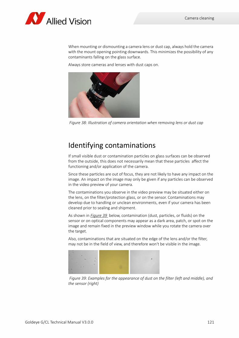
Camera cleaning
When mounting or dismounting a camera lens or dust cap, always hold the camera with the mount opening pointing downwards. This minimizes the possibility of any contaminants falling on the glass surface.
Always store cameras and lenses with dust caps on.
Identifying contaminationsIf small visible dust or contamination particles on glass surfaces can be observed from the outside, this does not necessarily mean that these particles affect the functioning and/or application of the camera.
Since these particles are out of focus, they are not likely to have any impact on the image. An impact on the image may only be given if any particles can be observed in the video preview of your camera.
The contaminations you observe in the video preview may be situated either on the lens, on the filter/protection glass, or on the sensor. Contaminations may develop due to handling or unclean environments, even if your camera has been cleaned prior to sealing and shipment.
As shown in Figure 39 below, contamination (dust, particles, or fluids) on the sensor or on optical components may appear as a dark area, patch, or spot on the image and remain fixed in the preview window while you rotate the camera over the target.
Also, contaminations that are situated on the edge of the lens and/or the filter, may not be in the field of view, and therefore won‘t be visible in the image.
Figure 38: Illustration of camera orientation when removing lens or dust cap
Figure 39: Examples for the appearance of dust on the filter (left and middle), and the sensor (right)
121Goldeye G/CL Technical Manual V3.0.0
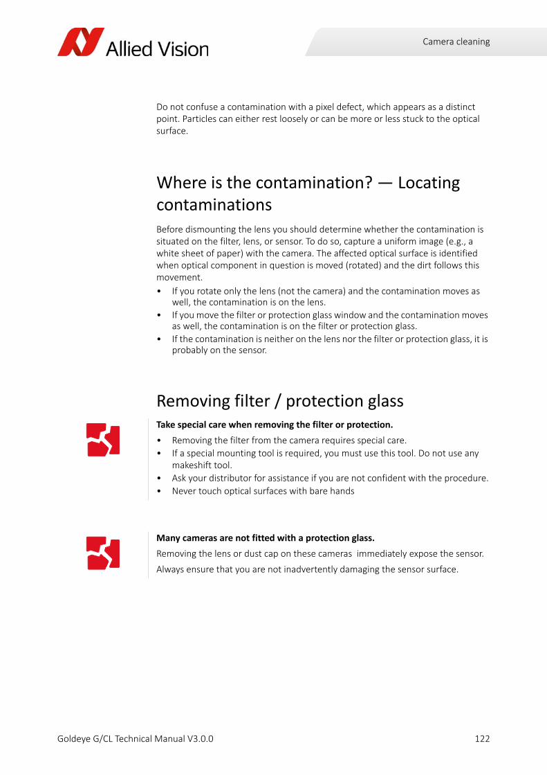
Camera cleaning
Do not confuse a contamination with a pixel defect, which appears as a distinct point. Particles can either rest loosely or can be more or less stuck to the optical surface.
Where is the contamination? — Locating contaminationsBefore dismounting the lens you should determine whether the contamination is situated on the filter, lens, or sensor. To do so, capture a uniform image (e.g., a white sheet of paper) with the camera. The affected optical surface is identified when optical component in question is moved (rotated) and the dirt follows this movement.
• If you rotate only the lens (not the camera) and the contamination moves as well, the contamination is on the lens.
• If you move the filter or protection glass window and the contamination moves as well, the contamination is on the filter or protection glass.
• If the contamination is neither on the lens nor the filter or protection glass, it is probably on the sensor.
Removing filter / protection glass Take special care when removing the filter or protection.
• Removing the filter from the camera requires special care.
• If a special mounting tool is required, you must use this tool. Do not use any makeshift tool.
• Ask your distributor for assistance if you are not confident with the procedure.
• Never touch optical surfaces with bare hands
Many cameras are not fitted with a protection glass.
Removing the lens or dust cap on these cameras immediately expose the sensor.
Always ensure that you are not inadvertently damaging the sensor surface.
122Goldeye G/CL Technical Manual V3.0.0

Camera cleaning
Cleaning instructions
Carry out all cleaning operations (on lenses, filter or protection glass, and sensor) in a clean dust‐free room. The optical components are very fragile, therefore you must not touch them with your fingers or any hard material.
1. Unplug the camera from any power supply before cleaning.
Figure 40: Camera mount without filter, directly exposing the sensor.
Use proper cleaning materials when cleaning glass surfaces.
• Never wipe lenses with dry swabs or tissue ‐ this may cause scratches.
• As a cleaning tool, use only lens cleaning tabs or a lens cleaning tissue wrapped around a small piece of plastic. The lens cleaning tissue must be chemically pure and free from silicones and other additives.
• Do not use metal tools.
• Do not use any disposable cotton cosmetic swabs; they may contain contami‐nants.
• Do not use cosmetic cotton.
• Do not use consumer eyeglass cleaning cloths pretreated with silicone.
• Do not use fibrous material that may get caught in small gaps.
• As cleaning liquid, use only optics cleaner (60% ethyl alcohol, 40% ether) or isopropyl alcohol.
Never use aggressive cleaners like benzine or spirits. Using cleaners like that may damage the surface.
123Goldeye G/CL Technical Manual V3.0.0
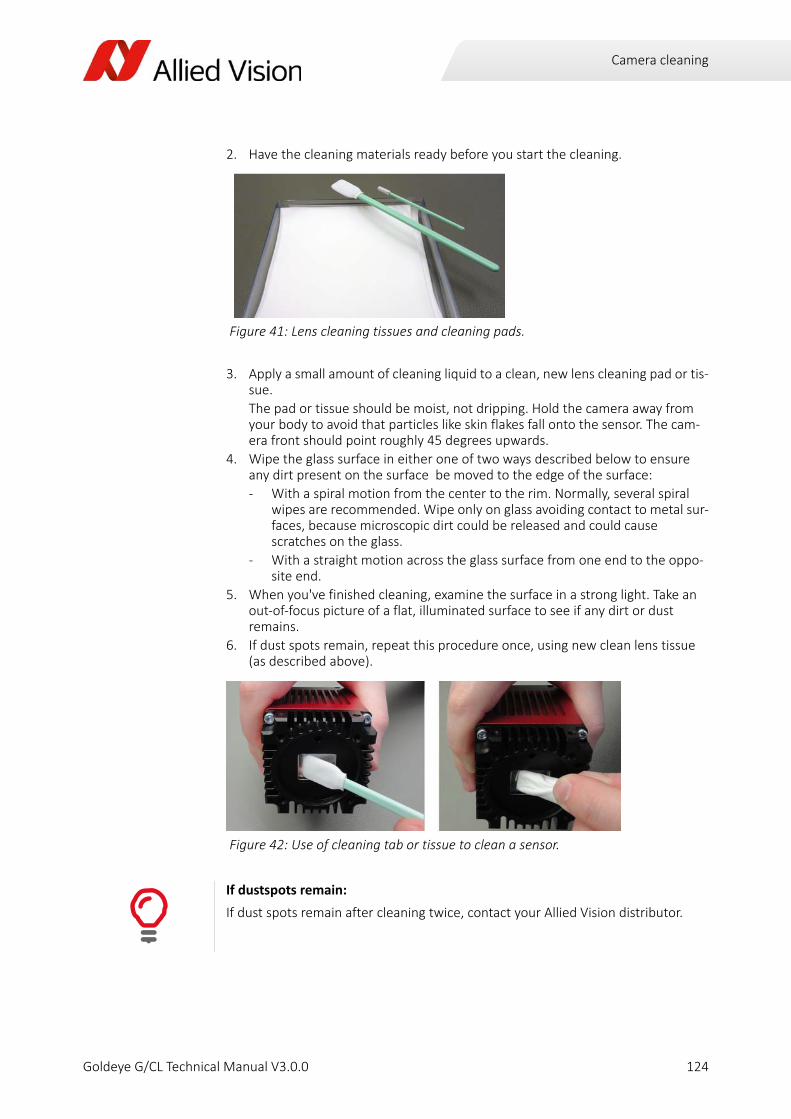
Camera cleaning
2. Have the cleaning materials ready before you start the cleaning.
3. Apply a small amount of cleaning liquid to a clean, new lens cleaning pad or tis‐sue.
The pad or tissue should be moist, not dripping. Hold the camera away from your body to avoid that particles like skin flakes fall onto the sensor. The cam‐era front should point roughly 45 degrees upwards.
4. Wipe the glass surface in either one of two ways described below to ensure any dirt present on the surface be moved to the edge of the surface:
‐ With a spiral motion from the center to the rim. Normally, several spiral wipes are recommended. Wipe only on glass avoiding contact to metal sur‐faces, because microscopic dirt could be released and could cause scratches on the glass.
‐ With a straight motion across the glass surface from one end to the oppo‐site end.
5. When you've finished cleaning, examine the surface in a strong light. Take an out‐of‐focus picture of a flat, illuminated surface to see if any dirt or dust remains.
6. If dust spots remain, repeat this procedure once, using new clean lens tissue (as described above).
Figure 41: Lens cleaning tissues and cleaning pads.
Figure 42: Use of cleaning tab or tissue to clean a sensor.
If dustspots remain:
If dust spots remain after cleaning twice, contact your Allied Vision distributor.
124Goldeye G/CL Technical Manual V3.0.0

Camera cleaning
Use of compressed air
Figure 43: How not to use compressed air
Dangers when using compressed air.
As a general precaution, you should never use compressed air to clean a camera.
If you want to use compressed air in spite of all warnings, consider the following:
• Use an air blower / compressed air only if you are familiar with cleaning a cam‐era with this instrument.
• Compressed air may blow dust into cameras and lenses.
• High pressure air may crack the sensor or glass you want to clean.
Therefore, keep the pressure at a moderate strength only:
‐ The pressure at the tube should be less than 1 bar (15 psi)
‐ Operating distance: 5–30 cm
• The pressurized air must be dust‐filtered and oil‐free.
• Use ionized air only to avoid any static charge.
• Also, using ionized air helps to remove any dirt stuck to the optical component because of static electricity.
125Goldeye G/CL Technical Manual V3.0.0

Index
Goldeye G/CL Technical Manual V3.0.0

Index
AAccessoriesBandpass filters . . . . . . . . . . . . . . . . . . . . . . . . . .62Camera Link adapters . . . . . . . . . . . . . . . . . . . . .59Ethernet adapters . . . . . . . . . . . . . . . . . . . . . . . .59Heat sink set . . . . . . . . . . . . . . . . . . . . . . . . . . . . .62Hirose 12‐pin . . . . . . . . . . . . . . . . . . . . . . . . . . . .60Hirose 4‐pin . . . . . . . . . . . . . . . . . . . . . . . . . . . . .61Mount adapters . . . . . . . . . . . . . . . . . . . . . . . . . .61Power adapters. . . . . . . . . . . . . . . . . . . . . . . . . . .60
Advanced Features . . . . . . . . . . . . . . . . . . . . . . . . . . 3Allied VisionAddresses and areas . . . . . . . . . . . . . . . . . . . . . .18Support . . . . . . . . . . . . . . . . . . . . . . . . . . . . . . . . .17
Appliance classification . . . . . . . . . . . . . . . . . . . . . . . 9Available camera controls . . . . . . . . . . . . . . . . . . .108
BBackground correction (BC) . . . . . . . . . . . . . . . . .105Bandpass filter . . . . . . . . . . . . . . . . . . . . . . . . . . . . .73Binning . . . . . . . . . . . . . . . . . . . . . . . . . . . . . . . . . .107Block diagramImage processing chain . . . . . . . . . . . . . . . . . . .100Input signal . . . . . . . . . . . . . . . . . . . . . . . . . . . . . .94Isolated input . . . . . . . . . . . . . . . . . . . . . . . . . . . .90Isolated output . . . . . . . . . . . . . . . . . . . . . . . . . . .92Signal output. . . . . . . . . . . . . . . . . . . . . . . . . . . . .95
CCamera cleaningCompressed air. . . . . . . . . . . . . . . . . . . . . . . . . .125Identifying contaminations . . . . . . . . . . . . . . . .121Locating contaminations . . . . . . . . . . . . . . . . . .122Necessity . . . . . . . . . . . . . . . . . . . . . . . . . . . . . . .120
Camera controls. . . . . . . . . . . . . . . . . . . . . . . . . . .108Camera Link . . . . . . . . . . . . . . . . . . . . . . . . . . . . . . .83CE conformity. . . . . . . . . . . . . . . . . . . . . . . . . . . . . . . 7CL‐008Data sheet imaging . . . . . . . . . . . . . . . . . . . . . . .35Data sheet output . . . . . . . . . . . . . . . . . . . . . . . .36General purpose inputs/outputs . . . . . . . . . . . .36Mechanics. . . . . . . . . . . . . . . . . . . . . . . . . . . . . . .36Operating conditions . . . . . . . . . . . . . . . . . . . . . .36Resolution and ROI. . . . . . . . . . . . . . . . . . . . . . . .38
Spectral sensitivity . . . . . . . . . . . . . . . . . . . . . . . . 37CL‐032Data sheet imaging . . . . . . . . . . . . . . . . . . . . . . . 39Data sheet output . . . . . . . . . . . . . . . . . . . . . . . . 40General purpose inputs/outputs . . . . . . . . . . . . 40Mechanics. . . . . . . . . . . . . . . . . . . . . . . . . . . . . . . 40Operating conditions . . . . . . . . . . . . . . . . . . . . . . 40Resolution and ROI . . . . . . . . . . . . . . . . . . . . . . . 42Spectral sensitivity . . . . . . . . . . . . . . . . . . . . . . . . 41
CL‐033Data sheet imaging . . . . . . . . . . . . . . . . . . . . . . . 43Data sheet output . . . . . . . . . . . . . . . . . . . . . . . . 44General purpose inputs/outputs . . . . . . . . . . . . 44Mechanics. . . . . . . . . . . . . . . . . . . . . . . . . . . . . . . 44Operating conditions . . . . . . . . . . . . . . . . . . . . . . 44Resolution and ROI . . . . . . . . . . . . . . . . . . . . . . . 46Spectral sensitivity . . . . . . . . . . . . . . . . . . . . . . . . 45
Cleaning instructions. . . . . . . . . . . . . . . . . . . . . . . 123C‐Mount adapterFilter change. . . . . . . . . . . . . . . . . . . . . . . . . . . . . 65Specifications . . . . . . . . . . . . . . . . . . . . . . . . . . . . 65
Control signals . . . . . . . . . . . . . . . . . . . . . . . . . . . . . 94Cooling limits . . . . . . . . . . . . . . . . . . . . . . . . . . . . .112Correction data . . . . . . . . . . . . . . . . . . . . . . . . . . .103Customer supportAdditional documentation . . . . . . . . . . . . . . . . . 16Contact addresses . . . . . . . . . . . . . . . . . . . . . . . . 18Technical information . . . . . . . . . . . . . . . . . . . . . 17
DData sheet imagingCL‐008 . . . . . . . . . . . . . . . . . . . . . . . . . . . . . . . . . . 35CL‐032 . . . . . . . . . . . . . . . . . . . . . . . . . . . . . . . . . . 39CL‐033 . . . . . . . . . . . . . . . . . . . . . . . . . . . . . . . . . . 43G‐008 . . . . . . . . . . . . . . . . . . . . . . . . . . . . . . . . . . 20G‐032 . . . . . . . . . . . . . . . . . . . . . . . . . . . . . . . . . . 24G‐032 Cool . . . . . . . . . . . . . . . . . . . . . . . . . . . . . . 27G‐033 . . . . . . . . . . . . . . . . . . . . . . . . . . . . . . . . . . 31
Data sheet outputCL‐008 . . . . . . . . . . . . . . . . . . . . . . . . . . . . . . . . . . 36CL‐032 . . . . . . . . . . . . . . . . . . . . . . . . . . . . . . . . . . 40CL‐033 . . . . . . . . . . . . . . . . . . . . . . . . . . . . . . . . . . 44G‐008 . . . . . . . . . . . . . . . . . . . . . . . . . . . . . . . . . . 21G‐032 . . . . . . . . . . . . . . . . . . . . . . . . . . . . . . . . . . 25G‐032 Cool . . . . . . . . . . . . . . . . . . . . . . . . . . . . . . 28G‐033 . . . . . . . . . . . . . . . . . . . . . . . . . . . . . . . . . . 32
Defect pixel correction (DPC) . . . . . . . . . . . . . . . .106DelayIsolated input . . . . . . . . . . . . . . . . . . . . . . . . . . . . 90
127Goldeye G/CL Technical Manual V 3.0.0

Index
Isolated output . . . . . . . . . . . . . . . . . . . . . . . . . . .92DimensionsGoldeye CL Standard ‐ C‐Mount . . . . . . . . . . . . .48Goldeye CL Standard ‐ F‐Mount . . . . . . . . . . . . .49Goldeye CL Standard ‐ M42‐Mount . . . . . . . . . .50Goldeye G Cool ‐ C‐Mount. . . . . . . . . . . . . . . . . .54Goldeye G Cool ‐ F‐Mount. . . . . . . . . . . . . . . . . .55Goldeye G Cool ‐ M42‐Mount. . . . . . . . . . . . . . .56Goldeye G standard ‐ C‐Mount . . . . . . . . . . . . . .51Goldeye G standard ‐ F‐Mount . . . . . . . . . . . . . .52Goldeye G Standard ‐ M42‐Mount . . . . . . . . . . .53
Document history . . . . . . . . . . . . . . . . . . . . . . . . . .12
EExposure. . . . . . . . . . . . . . . . . . . . . . . . . . . . . . . . . .96External GND . . . . . . . . . . . . . . . . . . . . . . . . . . . . . .88External power. . . . . . . . . . . . . . . . . . . . . . . . . . . . .88
FFCC ‐ Class B Device. . . . . . . . . . . . . . . . . . . . . . . . . . 8Filter change . . . . . . . . . . . . . . . . . . . . . . . 65, 68, 71F‐Mount adapterFilter change . . . . . . . . . . . . . . . . . . . . . . . . . . . . .68Specifications . . . . . . . . . . . . . . . . . . . . . . . . . . . .68
Frame memory . . . . . . . . . . . . . . . . . . . . . . . . . . .108
GG‐008Data sheet imaging . . . . . . . . . . . . . . . . . . . . . . .20Data sheet output . . . . . . . . . . . . . . . . . . . . . . . .21General purpose inputs/outputs . . . . . . . . . . . .21Mechanics. . . . . . . . . . . . . . . . . . . . . . . . . . . . . . .21Operating conditions . . . . . . . . . . . . . . . . . . . . . .21Resolution and ROI. . . . . . . . . . . . . . . . . . . . . . . .23Spectral sensitivity . . . . . . . . . . . . . . . . . . . . . . . .22
G‐032Data sheet imaging . . . . . . . . . . . . . . . . . . . . . . .24Data sheet output . . . . . . . . . . . . . . . . . . . . . . . .25General purpose inputs/outputs . . . . . . . . . . . .25Mechanics. . . . . . . . . . . . . . . . . . . . . . . . . . . . . . .25Operating conditions . . . . . . . . . . . . . . . . . . . . . .25
Resolution and ROI . . . . . . . . . . . . . . . . . . . . . . . 30Spectral sensitivity . . . . . . . . . . . . . . . . . . . . . . . . 29
G‐032 CoolData sheet imaging . . . . . . . . . . . . . . . . . . . . . . . 27Data sheet output . . . . . . . . . . . . . . . . . . . . . . . . 28General purpose inputs/outputs . . . . . . . . . . . . 28Mechanics. . . . . . . . . . . . . . . . . . . . . . . . . . . . . . . 28Operating conditions . . . . . . . . . . . . . . . . . . . . . . 28Resolution and ROI . . . . . . . . . . . . . . . . . . . . . . . 30Spectral sensitivity . . . . . . . . . . . . . . . . . . . . . . . . 29
G‐033Data sheet imaging . . . . . . . . . . . . . . . . . . . . . . . 31Data sheet output . . . . . . . . . . . . . . . . . . . . . . . . 32General purpose inputs/outputs . . . . . . . . . . . . 32Mechanics. . . . . . . . . . . . . . . . . . . . . . . . . . . . . . . 32Operating conditions . . . . . . . . . . . . . . . . . . . . . . 32Resolution and ROI . . . . . . . . . . . . . . . . . . . . . . . 34Spectral sensitivity . . . . . . . . . . . . . . . . . . . . . . . . 33
General purpose inputs/outputsCL‐008 . . . . . . . . . . . . . . . . . . . . . . . . . . . . . . . . . . 36CL‐032 . . . . . . . . . . . . . . . . . . . . . . . . . . . . . . . . . . 40CL‐033 . . . . . . . . . . . . . . . . . . . . . . . . . . . . . . . . . . 44G‐008 . . . . . . . . . . . . . . . . . . . . . . . . . . . . . . . . . . 21G‐032 . . . . . . . . . . . . . . . . . . . . . . . . . . . . . . . . . . 25G‐032 Cool . . . . . . . . . . . . . . . . . . . . . . . . . . . . . . 28G‐033 . . . . . . . . . . . . . . . . . . . . . . . . . . . . . . . . . . 32
GenICam. . . . . . . . . . . . . . . . . . . . . . . . . . . . . . .80, 83GenICam featuresBackground correction (BC) . . . . . . . . . . . . . . .105Binning . . . . . . . . . . . . . . . . . . . . . . . . . . . . . . . .107Correction data . . . . . . . . . . . . . . . . . . . . . . . . . 103Defect pixel correction (DPC) . . . . . . . . . . . . . . 106Look‐up table (LUT) . . . . . . . . . . . . . . . . . . . . . . 107Non‐uniformity correction (NUC) . . . . . . . . . . . 103
Gigabit Ethernet . . . . . . . . . . . . . . . . . . . . . . . . . . . 80GigE. . . . . . . . . . . . . . . . . . . . . . . . . . . . . . . . . . . . . . 80GigE Installation Manual. . . . . . . . . . . . . . . . . . . . . 82GigE status LEDs . . . . . . . . . . . . . . . . . . . . . . . . . . . 81
HHirose 12‐pin connectorPin assignment . . . . . . . . . . . . . . . . . . . . . . . . . . . 87
Hirose 4‐pin connectorPin assignment . . . . . . . . . . . . . . . . . . . . . . . . . . . 88
128Goldeye G/CL Technical Manual V 3.0.0

Index
II/O connectors . . . . . . . . . . . . . . . . . . . . . . . . . . . . .86Image corrections . . . . . . . . . . . . . . . . . . . . . . . . .103Frame memory . . . . . . . . . . . . . . . . . . . . . . . . . .108Non‐uniformity correction (NUC) . . . . . . . . . . .103
Image processing. . . . . . . . . . . . . . . . . . . . . . . . . .100Background correction (BC) . . . . . . . . . . . . . . .105Binning . . . . . . . . . . . . . . . . . . . . . . . . . . . . . . . .107Defect pixel correction (DPC) . . . . . . . . . . . . . .106Look‐up table (LUT) . . . . . . . . . . . . . . . . . . . . . .107
In 1 ‐ non‐isolated . . . . . . . . . . . . . . . . . . . . . . . . . .89In 2 ‐ opto‐isolated . . . . . . . . . . . . . . . . . . . . . . . . .89Isolated inputDelay . . . . . . . . . . . . . . . . . . . . . . . . . . . . . . . . . . .90
Isolated Out Power . . . . . . . . . . . . . . . . . . . . . . . . .89
KKey features . . . . . . . . . . . . . . . . . . . . . . . . . . . . . . . . 2
LLook‐up table (LUT) . . . . . . . . . . . . . . . . . . . . . . . .107
MM42‐Mount adapterFilter change . . . . . . . . . . . . . . . . . . . . . . . . . . . . .71Specifications . . . . . . . . . . . . . . . . . . . . . . . . . . . .70
MechanicsCL‐008 . . . . . . . . . . . . . . . . . . . . . . . . . . . . . . . . . .36CL‐032 . . . . . . . . . . . . . . . . . . . . . . . . . . . . . . . . . .40CL‐033 . . . . . . . . . . . . . . . . . . . . . . . . . . . . . . . . . .44G‐008. . . . . . . . . . . . . . . . . . . . . . . . . . . . . . . . . . .21G‐032. . . . . . . . . . . . . . . . . . . . . . . . . . . . . . . . . . .25G‐032 Cool . . . . . . . . . . . . . . . . . . . . . . . . . . . . . .28G‐033. . . . . . . . . . . . . . . . . . . . . . . . . . . . . . . . . . .32
Modular options . . . . . . . . . . . . . . . . . . . . . . . . . . . . 2
NNon‐uniformity correction (NUC) . . . . . . . . . . . . 103
OOperating conditionsCL‐008 . . . . . . . . . . . . . . . . . . . . . . . . . . . . . . . . . . 36CL‐032 . . . . . . . . . . . . . . . . . . . . . . . . . . . . . . . . . . 40CL‐033 . . . . . . . . . . . . . . . . . . . . . . . . . . . . . . . . . . 44G‐008 . . . . . . . . . . . . . . . . . . . . . . . . . . . . . . . . . . 21G‐032 . . . . . . . . . . . . . . . . . . . . . . . . . . . . . . . . . . 25G‐032 Cool . . . . . . . . . . . . . . . . . . . . . . . . . . . . . . 28G‐033 . . . . . . . . . . . . . . . . . . . . . . . . . . . . . . . . . . 32
Out 1 ‐ non‐isolated . . . . . . . . . . . . . . . . . . . . . . . . 91Out 2 ‐ opto‐isolated. . . . . . . . . . . . . . . . . . . . . . . . 91Out 3 ‐ opto‐isolated. . . . . . . . . . . . . . . . . . . . . . . . 91
PPin assignment . . . . . . . . . . . . . . . . . . . . . . . . . . . . 86External GND . . . . . . . . . . . . . . . . . . . . . . . . . . . . 88External power . . . . . . . . . . . . . . . . . . . . . . . . . . . 88Hirose 12‐pin connector . . . . . . . . . . . . . . . . . . . 87Hirose 4‐pin connector . . . . . . . . . . . . . . . . . . . . 88In 1 ‐ non‐isolated . . . . . . . . . . . . . . . . . . . . . . . . 89In 2 ‐ opto‐isolated. . . . . . . . . . . . . . . . . . . . . . . . 89Isolated Out Power . . . . . . . . . . . . . . . . . . . . . . . 89Out 1 ‐ non‐isolated. . . . . . . . . . . . . . . . . . . . . . . 91Out 2 ‐ opto‐isolated . . . . . . . . . . . . . . . . . . . . . . 91Out 3 ‐ opto‐isolated . . . . . . . . . . . . . . . . . . . . . . 91RxD . . . . . . . . . . . . . . . . . . . . . . . . . . . . . . . . . . . . 88TxD. . . . . . . . . . . . . . . . . . . . . . . . . . . . . . . . . . . . . 88
Pins 12‐pin HirosePin 1 . . . . . . . . . . . . . . . . . . . . . . . . . . . . . . . . . . . 88Pin 10 . . . . . . . . . . . . . . . . . . . . . . . . . . . . . . . . . . 89Pin 11 . . . . . . . . . . . . . . . . . . . . . . . . . . . . . . . . . . 89Pin 12 . . . . . . . . . . . . . . . . . . . . . . . . . . . . . . . . . . 91Pin 2 . . . . . . . . . . . . . . . . . . . . . . . . . . . . . . . . . . . 88Pin 4 . . . . . . . . . . . . . . . . . . . . . . . . . . . . . . . . . . . 89Pin 5 . . . . . . . . . . . . . . . . . . . . . . . . . . . . . . . . . . . 91Pin 6 . . . . . . . . . . . . . . . . . . . . . . . . . . . . . . . . . . . 91Pin 8 . . . . . . . . . . . . . . . . . . . . . . . . . . . . . . . . . . . 88Pin 9 . . . . . . . . . . . . . . . . . . . . . . . . . . . . . . . . . . . 88
Power Supply . . . . . . . . . . . . . . . . . . . . . . . . . . . . . . 77
129Goldeye G/CL Technical Manual V 3.0.0
Index
QQuick overviewEthernet adapter . . . . . . . . . . . . . . . . . . . . . . . . .82
RResolution and ROICL‐008 . . . . . . . . . . . . . . . . . . . . . . . . . . . . . . . . . .38CL‐032 . . . . . . . . . . . . . . . . . . . . . . . . . . . . . . . . . .42CL‐033 . . . . . . . . . . . . . . . . . . . . . . . . . . . . . . . . . .46G‐008. . . . . . . . . . . . . . . . . . . . . . . . . . . . . . . . . . .23G‐032. . . . . . . . . . . . . . . . . . . . . . . . . . . . . . . . . . .30G‐032 Cool . . . . . . . . . . . . . . . . . . . . . . . . . . . . . .30G‐033. . . . . . . . . . . . . . . . . . . . . . . . . . . . . . . . . . .34
RS‐232RxD . . . . . . . . . . . . . . . . . . . . . . . . . . . . . . . . . . . .88TxD. . . . . . . . . . . . . . . . . . . . . . . . . . . . . . . . . . . . .88
RxD . . . . . . . . . . . . . . . . . . . . . . . . . . . . . . . . . . . . . .88
SSensorposition accuracy . . . . . . . . . . . . . . . . . . . . . . . . .57
SpecificationsC‐Mount adapter . . . . . . . . . . . . . . . . . . . . . . . . .65F‐Mount adapter . . . . . . . . . . . . . . . . . . . . . . . . .68M42‐Mount adapter . . . . . . . . . . . . . . . . . . . . . .70
Spectral sensitivityCL‐008 . . . . . . . . . . . . . . . . . . . . . . . . . . . . . . . . . .37CL‐032 . . . . . . . . . . . . . . . . . . . . . . . . . . . . . . . . . .41CL‐033 . . . . . . . . . . . . . . . . . . . . . . . . . . . . . . . . . .45G‐008. . . . . . . . . . . . . . . . . . . . . . . . . . . . . . . . . . .22G‐032. . . . . . . . . . . . . . . . . . . . . . . . . . . . . . . . . . .29G‐032 Cool . . . . . . . . . . . . . . . . . . . . . . . . . . . . . .29G‐033. . . . . . . . . . . . . . . . . . . . . . . . . . . . . . . . . . .33
Status LEDsGigE . . . . . . . . . . . . . . . . . . . . . . . . . . . . . . . . . . . .81
Support. . . . . . . . . . . . . . . . . . . . . . . . . . . . . . . . . . .17Additional documentation. . . . . . . . . . . . . . . . . .16Contact addresses . . . . . . . . . . . . . . . . . . . . . . . .18Technical information . . . . . . . . . . . . . . . . . . . . .17
TTarget group. . . . . . . . . . . . . . . . . . . . . . . . . . . . . . . . 9TemperatureControl . . . . . . . . . . . . . . . . . . . . . . . . . . . . . . . .110Cooling limits . . . . . . . . . . . . . . . . . . . . . . . . . . .112Emergency shutdown . . . . . . . . . . . . . . . . . . . . 115Operational statuses . . . . . . . . . . . . . . . . . . . . . 114Setpoints . . . . . . . . . . . . . . . . . . . . . . . . . . . . . . . 112
TriggerNotes. . . . . . . . . . . . . . . . . . . . . . . . . . . . . . . . . . . 96Rules . . . . . . . . . . . . . . . . . . . . . . . . . . . . . . . . . . . 97Timing diagram. . . . . . . . . . . . . . . . . . . . . . . . . . . 96
TriggeringDuring the Idle state . . . . . . . . . . . . . . . . . . . . . . 97During the Readout state . . . . . . . . . . . . . . . . . . 97
TxD . . . . . . . . . . . . . . . . . . . . . . . . . . . . . . . . . . . . . . 88
WWarm‐up period . . . . . . . . . . . . . . . . . . . . . . . . . . 110WEEE compliance . . . . . . . . . . . . . . . . . . . . . . . . . . . 7
130Goldeye G/CL Technical Manual V 3.0.0


![Phosphine Chemistry - Sigma-Aldrich · Phosphine Chemistry Vol. 8, No. 4 ... NCH Cl H3C CH3 362565-1G 1 g 362565-5G 5 g ... [1079-66-9] C 12H 10ClP FW 220.63 P Cl C39601-25G 25 g](https://static.fdocuments.in/doc/165x107/5bb3be6309d3f2653c8c4372/phosphine-chemistry-sigma-aldrich-phosphine-chemistry-vol-8-no-4-nch.jpg)