55 B.C. L. R EV. (forthcoming May 2014) The Military-Environmental

UNIT – I (SNME)
PART – A
1) Write an expression of volumetric strain for a rectangular bar subjected to an axial load P. (Nov/Dec
2018)
= (1 2 )vl
el
2) What does the radius of mohr’s circle refer to? (May/June 2017)
The radius of mohr’s circle refers to the maximum shear stress.
3) Define principle plane (May /June 2016)
The plane which have no shear stress are known as principle planes.
4) Obtain the relation between E and K (May/June 2016) (Apr/May 2018)
2
2
2E 3K 1 3K 1 2
m
E Young 's modulus N / mm
K Bulk modulus N / mm
1poisson 's ratio
m
5) Differentiate elasticity and elastic limit (Nov/Dec 2015)
Elasticity
The body which regains its original position on the removal of the force that property is known as
Elasticity
Elastic limit
There is always a limiting values of load upto which the strain totally disappears on the removal of load
the stress corresponding to this load is known as Elastic limit
6) What is principle of super position? (Nov/Dec 2015)
In some cases, interior cross section of a body subjected to external axial forces. In such cases, the
forces are split up and their effects are considered on individual section. The total deformation is equal to the
algebraic sum of the deformation individual section. This principle of finding the resultant deformation is
known as principle of super position.
1 1 2 2 3 3P l P l P l .....l
AE
7) What do you mean by thermal stresses?(Apr/ May 2015) (Apr/ May 2019)
When the temperature varies, the bar will tends to expands or contracts, but the same is prevented by
external forces or by fixing the bar ends, the temperature stress will be produced in that bar.
AMSCE - 110
1

8) Draw the Mohr’s circle for the state of pure shear in a strained body and mark all salient points in it
(Apr/ May 2015)
9) Derive a relation for change in length of a bar hanging freely under its own weight (May / June 2017)
(Nov/ Dec 2014)
A bar of length - l (meter)
area – A (m2)
Fixed at one end ρ – kg/m3
Force acting down at CD= weight of bar CDEF = Aρy × 9.81
Force at CD A
A
y 9.81
A
29.81 y N / m
y stress is directly propotional to y
0
2 2
0
9.81 yStrain in length dy
E E
9.81 yElangation in dy dy
lE
9.81 yTotal elangation of bar(Sl) dy
lE
9.81 y y 9.81
lE 2 2E
τ
τ
τ
τ
0 σ2 = τ σ1 = τ
τmax = τ
ℓ
F E
dy
y D
B A
C
AMSCE - 110
1

10) Write the relationship between shear modulus & young’s modulus of elasticity (Nov/ Dec 2014)
1
E 2G 1 2G 1m
11) Define young’s modulus (Nov/ Dec 2016)
When a body is stressed within elastic limit, the ratio of stress is constant and that constant is known as
Young’s modulus.
12) What do you mean by principal planes and principal stress? (Nov/ Dec 2016) (Nov/ Dec 2017) (Apr/
May 2018) (Apr/ May 2019)
Principal plane:
The plane which have no shear stress are known as principal plane
Principal Stress:
The magnitude of normal stress, acting on a principal plane are known as principal stress
13) Define Bulk – modulus. (Nov/Dec 2017)
The ratio of direct stress to volumetric strain
K = Direct stress / Volumetric strain.
14) State Hooke’s law
It states when a material is loaded, within its elastics limit, the stress is directly proportional to the
strain.
15) Define strain energy
Whenever a body is strained, some amount of energy is absorbed in the body. The energy which is
absorbed in the body due to straining effect is known as strain energy.
16) Define Poisson’s ratio. (Nov/Dec 2018)
When a body is stressed, within it’s elastic limit, the ratio of lateral strain to the longitudinal strain is
constant for a given material. Poisson’s ratio
1
or Lateral strain / Longitudinalstrainm
17) What is compounds bar?
A composite bar composed of two or more different material joined together such that system is
elongated or compressed in a single unit.
18) Define strain
When a body is subjected to an external force, there is some change of dimension in the body.
Numerically the strain is equal to the ratio change in length to the original length of the body
Strain (e) = change in length / Original length L / L
AMSCE - 110
1

19) Define stress
When an external forces acts on a body, it undergoes deformation. At the same time the body resists
deformation. The magnitude of the resistance force is numerically equal to the applied force. This internal
resistance force per unit area is called stress. Stress σ = Force/Area, P/A Unit N/mm2.
20) Define shear stress and shear strain.
The two equal and opposite force act tangentially on any cross section plane of the body tending to
slide one part of the body over the other part. The stress induced is called shear stress and corresponding strain
is known as shear strain.
21) Define – Lateral strain.
The strain right to the direction of the applied load is called lateral strain.
22) Define – longitudinal strain
When a body is subjected to axis load P, the length of the body is increased. The axial deformation of
the length of the body is called longitudinal strain.
23) A rod of diameter 30 mm and length 400 mm was found to eligible 0.35 mm. When it was subjected to
a load of 65 KN. Compute the modulus of elasticity of material of this rod.
3
2
3 2
P P 65 10 400l E
AE A l30 0.35
4
E 105.09 10 N / mm
24) The Young’s modulus and the shear modulus of material are 120GPa and 45GPa respectively. What
is it Bulk modulus?
9 2 9 2
3 2 3 2
E 120 10 N / m G 45 10 N / m
120 10 N / mm 45 10 N / mm
33
3
3 3 3
3
3
3 2
9KGE
3K G
9K 45 10120 10
3K 45 10
120 10 3K 45 10 9K 45 10
3K 45 10 3.375 K
45 10 0.375 K
K 120 10 N / mm
AMSCE - 110
1

PART – B
1) A steel rod of 3cm diameter and 5m long is connected to two grips and the rod is maintained at a
temperature of 950C. Determine the stress and pull exerted when the temperature falls to 30
0C, if
(i) the ends do not yield and
(ii) the ends yield by 0.12cm. Take E=2x10⁵MN/m
2 and α=12x10
-6/0C (Apr/May 2019)
2 2
0
1
0
2
0
1 2
2
d=30mm
= 225 mm4
5000
T = 95 C
T = 30 C
T = T T 65 C
(i) when the ends do not yield
stress = = 156N/mm
Pull in the rod = stress x area = 156x225 = 110269.9 N
(ii) When the ends yield
A xd
L mm
TE
2
by 0.12cm ( =1.2mm)
( - )stress = 108N/mm
Pull in the rod = stress x area = 108x225 = 76340.7 N
TLxE
L
2) An elemental cube is subjected to tensile stresses of 30 N/mm2 and 10 N/mm
2 acting on two mutually
perpendicular planes and a shear stress of 10 N/mm2 on these planes. Draw the Mohr’s circle of stresses
and hence or otherwise determine the magnitude and directions of principal stresses and also the greatest
shear stress. (Apr/May 2019)
Major tensile stress (σ1) = 30N/mm2
Minor tensile stress (σ2) = 10 N/mm2
Shear stress (τ) = 10 N/mm2
Location of principle planes,
θ = Angle, which one of the principle planes makes with the stress of 10 N/mm2
1 2
1
2 2 10tan 2 1
30 10
2 tan 1 45 or 225
22 5' or 112 5'
Principle stress
Major principle stress =
2
21 2 1 2
2 2
AMSCE - 110
1

2
2
2
30 10 30 1010
2 2
20 14.14 34.14 N / mm
Minor principle stress =
2
21 2 1 2
2 2
2
2
2
30 10 30 1010
2 2
20 14.14 5.86 N / mm
3) A reinforced short concrete column 250mm x 250mm in section is reinforced with 8 steel bars. The
total area of steel bars is 2500 mm2. The column carries a load of 390kN. If the modulus of elasticity of
steel is 15 times that of concrete. Find the stresses in concrete and steel. (Nov/Dec 2018)
s c
2
s
2
2
c
E 15E
A 2500mm
Area of concrete column = 250x250 = 62500mm
A 62500 2500 60000 mm
P = 390000N
s c
s c
s
s c c
c
s c
i)
E E
E15
E
15 ...1
s s c c
c c
c
2
c
2
s
P A A
390000 15 2500 60000
390000 97500
4N / mm
60N / mm
4) The stresses at a point in a bar are 200 N/mm2 (tensile) and 100 N/mm
2 (compressive). Determine the
resultant stress in magnitude and direction on a plane inclined at 600 to the axis of major stress. Also
determine the maximum shear stress in the material at the point. (Nov/Dec 2018)
Major Principal stress, σ1=200 N/mm2
Minor Principal stress, σ2= - 100 N/mm2
Angle inclined with major principal stress = 600
Angle inclined with minor principal stress = 900 - 60
0 = 30
0
AMSCE - 110
1
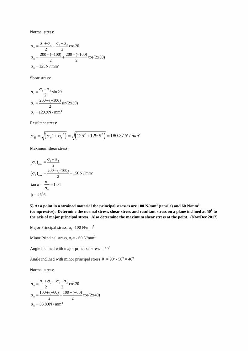
Normal stress:
1 2 1 2
n
n
2
n
cos 22 2
200 ( 100) 200 ( 100)cos(2x30)
2 2
125N / mm
Shear stress:
1 2
t
t
2
t
sin 22
200 ( 100)sin(2x30)
2
129.9N / mm
Resultant stress:
2 2 2 2 2125 129.9 180.27 /R n t N mm
Maximum shear stress:
1 2
t max
2
t max
t
n
0
2
200 ( 100)150N / mm
2
tan = 1.04
= 46 6'
5) At a point in a strained material the principal stresses are 100 N/mm2 (tensile) and 60 N/mm
2
(compressive). Determine the normal stress, shear stress and resultant stress on a plane inclined at 500 to
the axis of major principal stress. Also determine the maximum shear stress at the point. (Nov/Dec 2017)
Major Principal stress, σ1=100 N/mm2
Minor Principal stress, σ2= - 60 N/mm2
Angle inclined with major principal stress = 500
Angle inclined with minor principal stress = 900 - 50
0 = 40
0
Normal stress:
1 2 1 2
n
n
2
n
cos 22 2
100 ( 60) 100 ( 60)cos(2x40)
2 2
33.89N / mm
AMSCE - 110
1

Shear stress:
1 2
t
t
2
t
sin 22
100 ( 60)sin(2x40)
2
78.785N / mm
Resultant stress:
2 2 2 2 233.89 78.785 85.765 /R n t N mm
Maximum shear stress:
1 2
t max
2
t max
2
100 ( 60)80N / mm
2
6) A solid steel bar 40mm diameter 2m long passes centrally through a copper tube of internal diameter
40mm, thickness of metal 5mm and length 2m. The ends of the bar and tube are brazed together and a
tensile load of 150kN is applied axially to the compound bar. Assume Ec= 100GN/m2 and Es= 200GN/m
2
Find the stresses and load sheared by the steel and copper section (Apr/May 2018)
s
c
c c
d 40mm
t 5mm
d 40mm
D d 2t 40 2x5 50mm
P 150000N
2m
5 2
s
5 2
c
2
s s
2 2
2 2 2 2
c c c
2
E 2 10 N / mm
E 1 10 N / mm
A d4
40 1256.64 mm4
A D d 50 404 4
706.86 mm
s c
s c
5
s
s c c5
c
s c
i)
E E
E 2 10
E 1 10
2 ...1
AMSCE - 110
1

s s c c
c c
c
2
c
2
s
P A A
150000 2 1256.64 706.86
150000 2120.58
70.74N / mm
141.47N / mm
7) At a point within a body subjected to two mutually perpendicular directions, the tensile stresses are
80N/mm2 and 40N/mm
2respectively. Each stress is accompanied by shear stress of 60N/mm
2. Determine
the normal stress, shear stress and resultant stress on an oblique plane inclined at an angle of 450 with the
axis of minor tensile stress. (Apr/May 2018)
2
1
2
2
2
0
Major tensile stress =80N/mm
Minor tensile stress =40N/mm
Shear stress =60N/mm
Angle incline with minor axis ( )= 45
Normal Stress:
1 2 1 2
n
n
2
n
cos 2 sin 22 2
80 40 80 40cos(2x45) 60sin(2x45)
2 2
120N / mm
Shear stress:
1 2
t
t
2
t
sin 2 cos 22
80 40sin(2x45) 60cos(2 x 45)
2
20N / mm
Resultant stress:
2 2 2 2 2120 20 121.65 /R n t N mm
8) The bar shown in fig. Q.11(a) is subjected to a tensed load of 100 KN of the stress in middle portion is
limited to 150N/mm2. Determine the diameter of the middle portion. Find also the length of the middle
portion if the total elongation of the bar is to be 0.2 mm young modules is 2.1 x 10⁵ N/mm
2
(May / June 2017) 13-Marks
AMSCE - 110
1

Fig.Q.11(a)
Given: P = 100 KN = 100 x 103 N
Stress at middle portion, σ2 = 150 N/mm2
Total elongation δL = 0.2 mm
Young modulus, E = 2.1 x 10⁵ N/mm
2
Total length, L = 400 mm
To find:
i) Diameter of the middle portion, D2
ii) Length of the middle portion, L2
Solution
Stress at the middle portion, 2
2
Load p
Area A
3
2 2
2 2
p 100 10150
D D4 4
Diameter of middle portion, D2 = 29.14 mm
Let,
Length of first portion = L1
Length of middle portion = L2
Length of last portion = L3
We know that
Total elongation, 31 2
1 2 3
LL LpL
E A A A
a
160 KN 160 KN
400 mm
a
6 cm
dia
6 cm
dia
AMSCE - 110
1

3
31 2
52 2 2
1 2 3
3
31 2
52 2 2
LL L100 100.2
2.1 10D D D
4 4 4
LL L100 100.2
2.1 1060 29.14 60
4 4 4
3
31 2
5
LL L100 100.2
2826 666.57 28262.1 10
1 3 2
2 2
2 2
L L L0.2 0.476
2826 666.57
400 L L0.2 0.476
2826 666.57
L L4000.2 0.476
2826 2826 666.57
0.2 = 0.0673 – 1.684 x 10⁻⁴
L2 + 7.141 x 10⁻⁴
L2
0.2 = 0.0673 + 5.457 x 10⁻⁴
L2
24
0.2 0.0673L
5.457 10
L2 = 243.17 mm
Result
1) Diameter of middle portion, D2 = 29.14 mm
2) Length of middle portion, L2 = 243.17 mm
9) A bar of 30 mm diameter is subjected to a pull of 60KN. The measured extension on gauge length of
200 mm is 0.1 mm and change in diameter is 0.004 mm.
Calculate (May 2017) 13 Marks
(i) Young’s modulus
(ii) Poisson’s ratio and
(iii) Bulk modulus
Given:
Diameter, d = 30 mm
Pull, p = 60 KN = 60 x 103 N
Length, L = 200 mm
Change in Length, δL = 0.1 mm
Change in diameter, δd = 0.004 mm
AMSCE - 110
1

To Find:
(i) Young’s modulus
(ii) Poisson’s ratio and
(iii) Bulk modulus
Solution: we know that
te1 LateralstrainPoisson 's ratio 1
m longitudinalstrain e
Lateral strain t
b d te or or
b d t
4
t
d 0.004e 1.333 10
d 30
Longitudinal strain, 4L 0.1e 5 10
L 200
Substitute et and e in equation (1)
4
4
1 1.333 100.26
m 5 10
1Poisson 's ratio 0.26
m
Tensilestress
young 's mod ulus,ETensilestrain e
3
2 4
3 3
2 4
5 2
Load pstress
Area A
60 10E
d 5 104
60 10 60 10
0.35350 5 10
4
E 1.69 x10 N / mm
We know that,
Young’s modulus, 5
5 2
2E 3k 1
m
1.69 10 3k 1 2 0.26
Bulk mod ulus k 1.17 10 N / mm
Results:
(i) Poisson’s ratio = 1
m=0.26
AMSCE - 110
1

(ii) Young’s modulus = E = 1.69 x 10⁵ N/mm
2
(iii) Bulk modulus = k = 1.17 x 10⁵ N/mm
2
10) A steel bar 20mm in diameter 2m long is subjected to an axial pull of 50 KN. If E= 2×10⁵ N/mm
2 and
m = 3. Calculate the change in the i) Length ii) diameter iii) Volume (8 mark)
(May / June 2016)
Given data:
5 2
3
d 20 mm 2m p 50KN E 2 10 N / mm
2000mm 50 10
m 3
3 32
2
P / Ai) E
e / l
eE
P 50 10 50 10159.15 N / mm
A 314.16/ 4 20
4
5
4
159.15e 7.957 10
E 2 10
e
7.96 10 2000 1.59mm
Change in legnth 1.59 mm
4
4
4 3
3
1 1poisson 's ratio 0.33
m 3
d / dLateral strain
Linear strain /
d / d0.33
7.96 10
d / d 2.6268 10
d 2.6268 10 20 5.25 10 mm
change in dialmeter d 5.25 10
4 4
4
4 2
3
v / v / 2 d / d
v7.96 10 2 2.63 10
v
v2.7 10
v
V 2.7 10 20 20004
change in volume V 169.65 mm
AMSCE - 110
1

11) A mild steel bar 20 mm in diameter and 40 cm long is encase in a tube whose external diameter is 30
and internal diameter is 25 mm. The composite bar is heated through 80°C. Calculate the stress induced
in each metal 𝛂 for steel is 11.2 ×10⁻⁶ per °C; 𝛂 for brass is 11.2 ×10⁻⁶ per °C. E for steel is 2 ×10⁵
N/mm2 and E for brass is 1 ×10
5 N/mm
2 (8mark)
(May /June 2016)
Given
s s b
b b
6 6
s b
5 2 5 2
s b
2 2
s s
2 2 2
b b b
d 20mm 40cm 400mm
D 30 mm d 25mm t 80 C
11.2 10 / C 16.5 10 / C
E 2 10 N / mm E 1 10 N / mm
A d 314.16 mm4
A D d 215.98 mm4
Under equilibrium condition,
Compression in brass is equal to tension in steel i.e,
Load on brass(Pb) = load on steel (Ps)
b b s s
b
s b b b
s
s b
A A
A 215.980.687
A 314.16
0.687 ...1
Actual expansion of steel = Actual expansion of brass
s b
s s s b b b
s b
bs
s s b b s b
s b
s b
b s
s b
5 6b b
5 5
6 5
b b
b
2
b
t tE E
t tE E
tE E
0.68716.5 10 11.2 10 80 C
2 10 1 10
0.3435 5.3 10 10 80 42.4
1.3435 42.4
31.56 N / mm substitute
2
s
in equation1,
we get 21.68 N / mm
AMSCE - 110
1
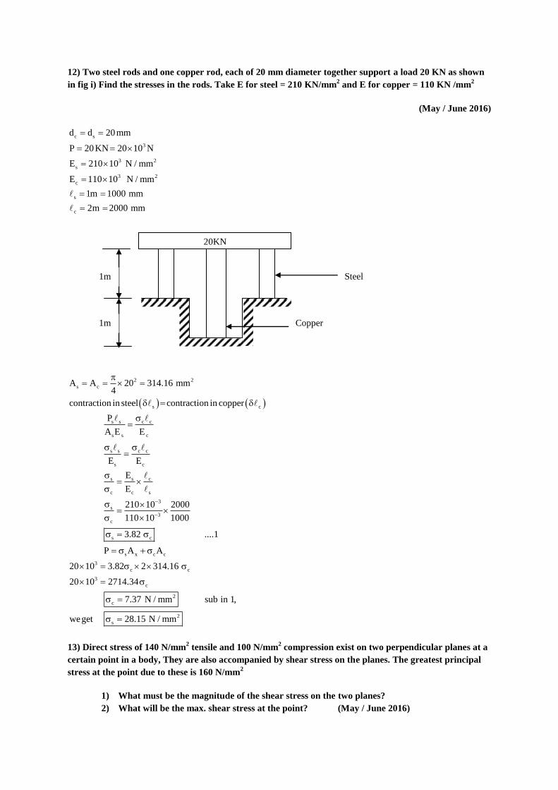
12) Two steel rods and one copper rod, each of 20 mm diameter together support a load 20 KN as shown
in fig i) Find the stresses in the rods. Take E for steel = 210 KN/mm2 and E for copper = 110 KN /mm
2
(May / June 2016)
c s
3
3 2
s
3 2
c
s
c
d d 20mm
P 20KN 20 10 N
E 210 10 N / mm
E 110 10 N / mm
1m 1000 mm
2m 2000 mm
2 2
s c
s c
s s c c
s s c
s s c c
s c
s s c
c c s
3
s
3
c
s c
s x c c
3
c c
3
A A 20 314.16 mm4
contraction in steel contraction in copper
P
A E E
E E
E
E
210 10 2000
1000110 10
3.82 ....1
P A A
20 10 3.82 2 314.16
20 10 2714.3
c
2
c
2
s
4
7.37 N / mm sub in 1,
weget 28.15 N / mm
13) Direct stress of 140 N/mm2 tensile and 100 N/mm
2 compression exist on two perpendicular planes at a
certain point in a body, They are also accompanied by shear stress on the planes. The greatest principal
stress at the point due to these is 160 N/mm2
1) What must be the magnitude of the shear stress on the two planes?
2) What will be the max. shear stress at the point? (May / June 2016)
20KN
Steel
Copper
1m
1m
AMSCE - 110
1
2 2 2
x y 1
xy
2
x y x y 2
1 xy
2
xy
140N / mm 100N / mm 160 N / mm
1 Shear stress( ) :
2 2
140 100 140 100160
2 2
2 2
xy
2 2
xy
2 2 2
xy
2
xy
160 20 120
140 120
140 120
72.11 N / mm
x y x y 2
2 xy
22
2
2
2
max
1 2
max
2
max
Min. principal stress,2 2
20 120 72.11
119.99 120 N / mm
120 N / mm comp
2.M ax. shear stress :
160 120
2 2
140 N / mm
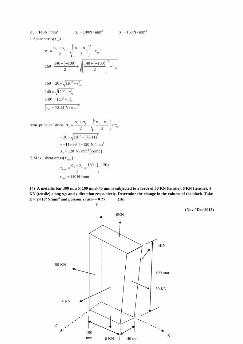
14) A metallic bar 300 mm × 100 mm×40 mm is subjected to a force of 50 KN (tensile), 6 KN (tensile), 4
KN (tensile) along x,y and z direction respectively. Determine the change in the volume of the block. Take
E = 2×10⁵ N/mm
2 and poisson’s ratio = 0.25 (16)
(Nov / Dec 2015)
50 KN
Z
100
mm 6 KN 40 mm X
50 KN
4KN
300 mm
Y
6KN
4 KN
AMSCE - 110
1
32x
x
yz
3y 2
y
zx
32z
z
xy
yx z
x
5 5 5
5
x 100mm y 300mm z 40mm
p 50 104.167 N / mm
A 300 40
p 6 101.5 N / mm
A 100 40
P 4 100.133N / mm
A 100 300
eE mE mE
4.167 0.25 1.5 0.25 0.133
2 10 2 10 2 10
14.167 0.25 1.5 0.25 0.
2 10
133
5
5
y x z
y
5
3.758751.879 10
2 10
eE mE mE
11.5 4.167 0.25 0.133 0.25
2 10
6
5
z x z
y
5
6
5
5
v x y z
5
3
0.4252.125 10
2 10
eE mE mE
10.133 4.167 0.25 1.5 0.25
2 10
1.283756.418 10
2 10
Ve e e e 1.4497 10
V
V 1.4497 10 300 100 40
V 17.396 17.40 mm
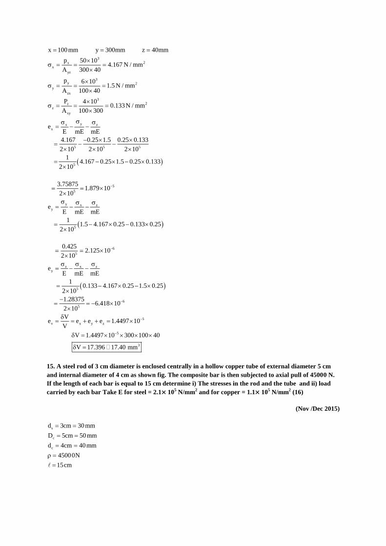
15. A steel rod of 3 cm diameter is enclosed centrally in a hollow copper tube of external diameter 5 cm
and internal diameter of 4 cm as shown fig. The composite bar is then subjected to axial pull of 45000 N.
If the length of each bar is equal to 15 cm determine i) The stresses in the rod and the tube and ii) load
carried by each bar Take E for steel = 2.1× 10⁵ N/mm
2 and for copper = 1.1× 10
5 N/mm
2 (16)
(Nov /Dec 2015)
s
c
c
d 3cm 30mm
D 5cm 50mm
d 4cm 40mm
45000N
15cm
AMSCE - 110
1

5 2
s
5 2
c
2
s s
2 2
2 2
c c c
2
E 2.1 10 N / mm
E 1.1 10 N / mm
A d4
30 706.86 mm4
A D d4
706.86 mm
s c
s c
5
s
s c c5
c
s c
i)
E E
E 2.1 10
E 1.1 10
1.91 ...1
s s c c
c c
c
P A A
4500 1.91 706.86 706.86
4500 2056.96
2
c
2
s
21.88N / mm subs. (1), we get,
41.78N / mm
P = 45000 N
4 cm
5 cm
3 cm
Steel rod Copper tube
15 cm
AMSCE - 110
1

c c c
s s s
ii)
P A 15466.09 N
P A 29532.61 N
16) At a point in a strained material the resultant intensity of stress across a vertical plane is 100MPa
tensile inclined at 35° clockwise to its normal. The normal component of intensity of stress across the
horizontal plane is 50 MPa compressive Determine graphically using Mohr’s circle method
i) The position of principal planes and stresses across them and
ii) The normal and tangential stresses across a plane which is 60° clockwise to the vertical plane
(Apr/ May 2016 )
Φ=110°
N
221° = 2θ
O
1 72 C
V M
x 50
Q L
P
S max 86.5
U
T
y 81.91
2 101 T
120° = 2θ
41° = 2θ
Z
50
100 sin35
50
100 sin35
100 sin35
100 sin35
100 sin35
100 sin35
100 MPa
50 MPa
100 MPa AMSCE - 110
1

1
2
max
1
2
i)
From
OV 72 MPa (Compressive)
OV 101 MPa (Tensile)
NZ 86.5 MPa(shear)
2 41 or 221
20.5
110.5
r
ii)
60
OQ 28MPa
PQ 75 MPa
OP 80 MPa
110
17) Derive an expression for change in length of a circular bar with uniformly varying diameter and
subjected to an axial tensile load P (8 mark) (Nov /Dec 2014)
Tensile stress in AB (σ1) 1
P
A
Elongation in AB (δl1) = 1
1
P
A E
lllly
for BC & CD
Total Elongation (δl) = 1 2 2l l l
= 31 2
1 2 3
PlPl Pl
A E A E A E
31 2
1 2 3
ll lPl
E A A A
18) A member is subject to point load as shown in Fig Calculate the force P2, necessary for equilibrium if
P1=45 KN; P3=450 KN and P4=130 KN. Determine the total elongation of the member, assuming the
modulus of elasticity to be 5 2E 2.1 10 N / mm (8 mark) (Nov /Dec 2014)
A1
A2
A3
P
l1
D C
B
A
P
l2 l3 AMSCE - 110
1

1 3 4
1 2 3 4
2
2
P 45KN P 450 KN P 130 KN
P P P P 0
45 P 450 130 0
P 365 KN
AB AB
AB
AB
3
5
AB
AB
P ll
A E
45 10 1200
625 2.1 10
l 0.414 mm(Tensile)
BC BC
BC
BC
3
5
BC
BC
P ll
A E
320 10 600
2500 2.1 10
l 0.3657 mm (Comp)
CD CD
CD
CD
3
5
CD
CD
P ll
A E
130 10 900
1250 2.1 10
l 0.4457 mm (Tansile)
AB BC CDl l l l 0.4914 mm
19) A compound tube consists of a steel tube 140 mm internal diameter and 160 mm external diameter
and an outer brass tube 160 mm internal diameter and 180 mm external diameter. The two tubes are of
same length. The compound tube carries an axial compression load of 900 KN. Find the stress and the
625 mm2
1250 mm2
2500 mm2
P4
1200 mm
D
C B
A
P1
600 mm 900 mm
P2 P3
A B
45 KN
365-450+130 45 KN
B C
320 KN
450+130 320 KN
C D
130 KN
-45+365-450 130
KN
AMSCE - 110
1

load carried by each tube and the amount of it shorten. Length of each tube is 140 mm. Take E for steel
as 2×10⁵N/mm
2 & for brass is 1×10
5N/mm
2 (16 mark) (Nov /Dec 2016) (Nov /Dec 2017)
s b
3
s b
5
s b s
5
b
2 2 2 2
s s s b b b
2
s b
s b
s
s b b
b
s s b b
b b
b
D 160 D 180 mm P 900KN
d 140mm d 160 mm 900 10
140 mm E 2 10 N / mm
E 1 10 N / mm
A D d A D b4 4
4712.39mm 5340.71 mm
E E
E2 ...1
E
P A A
900 4712.39 5340.71
60.95 N / m
2
2
s
s s s
b b b
m subin1, weget
121.91 N / mm
P A 574468.03 N
P A 32516.27 N
20) Two members are connected to carry a tensile force of 80 KN by a lap joint with two number of 20
mm diameter bolt. Find the shear stress induced in the bolt (3)
(Nov / Dec 2016)
3
2
2
P 80 10254.65 N / mm
A20
4
21) A point in a strained material is subjected to the stress as shown in fig. Locate the principle phone and
find the principle stress (7 marks) (Nov / Dec 2017)
60 N/mm2
60 N/mm2
40 N/mm2
40 N/mm2
B
D
A
C
AMSCE - 110
1

Stress on face AD & BC is not normal It is inclined at an angle 60° with face BC at AD stress can be resolved
into two components
Stress normal to face (BC or AD) = 60 sin90°
= 60 ×0.866 = 51.96 N/mm2
Stress normal to face (BC or AD) = 60 cos90°
= 60 ×0.5 = 30 N/mm2
Major tensile stress (σ1) = 51.9 N/mm2
Minor tensile stress (σ2) = 40 N/mm2
Shear stress (τ) = 30 N/mm2
Location of principle planes,
θ = Angle, which one of the principle planes makes with the stress of 40 N/mm2
1 2
1
2 2 30tan 2 4.999
51.96 40
2 tan 4.999 78 42' or 258 42'
39 21' or 129 21'
Principle stress
Major principle stress = 1 2 1 2n cos 2
2 2
30 N/mm2
30 N/mm2
30 N/mm2
30 N/mm2
51.96
N/mm2
51.96
N/mm2
40 N/mm2
40 N/mm2
AMSCE - 110
1

2
2
2
51.9 40 51.9 4030
2 2
45.98 30.6 76.58 N / mm
Minor principle stress =
2
21 2 1 2
2 2
2
2
2
51.9 40 51.9 4030
2 2
45.98 30.6 15.38 N / mm
22) A steel rod of 20 mm diameter passes centrally through a copper tube of 50 mm external diameter
and 40 mm internal diameter. The tube is closed at the end by rigid plates of negligible thickness. The
nuts are tightened lightly on the projecting part of the rod. If the temperature of the assembly is raised by
50℃. Calculate the stresses developed in copper and steel. Take E for steel as 5 22 10 N / mm and copper
as 5 21 10 N / mm and as for steel and copper as 6 612 10 C & 18 10 C (6 mark)
(Nov / Dec 2016)
s c t
2 2
s c
2 2 2
c c c c
5 2 6
s s
5 2 6
c c
d 20mm, D 50mm, A 50 C,
A 20 314.16 mm , d 40mm,4
A D d A 706.86 mm4
E 2 10 N / mm 12 10 / C
E 1 10 N / mm 18 10 / C
s s c c
c
s c c
s
c s
c s
c s
6c c
5 5
6 5
c
2
c
2
s
A A
A2.25 ...1
A
tE E
2.256 10 50
1 10 2 10
2.215 6 10 50 10 30
14.11N / mm subin 1
31.76 N / mm
23) A metallic bar 300 mm (x) × 100 mm(y) × 40 mm is subjected to a force of 5 KN tensile, 6KN (tensile)
and 4 KN (tensile) along x,y,z direction respectively. Determine the change in volume of the block. Take
E =2 × 10⁵ N/mm
2 and Poisson’s ratio = 0.25 (16 mark)
(Nov /Dec 2014)
AMSCE - 110
1

Solution
x y z
32x
x
yz
2
x
3y 2
y
zx
2
y
32z
z
xy
2
z
x 300mm y 100mm z 40mm
P 5KN P 6KN P 4KN
P 5 101.25 N / mm
A 100 40
1.25 N / mm
P 6 100.5 N / mm
A 30 40
0.5 N / mm
P 4 100.133 N / mm
A 100 300
0.133 N / mm
yx z
x
5 5 5
5
6
x
y x z
y
5 5 5
5
6
y
yz x
z
eE mE mE
1.25 0.5 0.25 0.133 0.25
2 10 2 10 2 10
11.25 0.125 0.0332
2 10
e 5.459 10
eE mE mE
0.5 1.25 0.25 0.133 0.25
2 10 2 10 2 10
10.5 0.125 0.0332
2 10
e 5.459 10
eE mE m
5 5 5
5
6
z
v x y z
6 7 6
6
3
E
0.133 1.25 0.25 0.5 0.25
2 10 2 10 2 10
10.133 0.3125 0.125
2 10
e 1.5225 10
Ve e e e
V
V5.459 10 7.715 10 1.5225 10
V
V 4.708 10 300 40 40
V 5.6496 mm
AMSCE - 110
1

Part – C
1) (i) Draw stress strain curve for mild steel and explain the salient points on it. (7)
We have studied in chapter of simple stress and strain, that whenever some external system of forces acts on a
body, it undergoes some deformation. If a body is stressed within its elastic limit, the deformation entirely
disappears as soon as the forces are removed. It has been also found that beyond the elastic limit, the
deformation does not disappear entirely, even after the removal of the forces and there remains some residual
deformation. We study this phenomenon, in a greater detail by referring to a tensile test or stress-strain diagram)
for a mild steel bar
Fig. 11 a (i) Mild Steel Bar
Take a specimen of mild steel bar of uniform section as shown in Fig. 11 a (i). Let this bar be subjected to a
gradually increasing pull (as applied by universal testing machine). If we plot the stresses along the vertical axis,
and the corresponding strains along the horizontal axis and draw a curve passing through the vicinity of all such
points, we shall obtain a graph as shown in Fig. 11 a (ii)
We see from the graph, that
(1). From points O to A is a straight line, which represents that the stress is linearly proportional to strain.
(2). From A to B, the curve slightly deviates from the straight line but the material still shows behaviour until
the curve reaches to point B, which is called elastic limit. Upto this point B if the load is removed the specimen
will still come back to its original position. It is thus obvious, that the Hooke's law holds good only up to this
limit. When the specimen is stressed beyond the elastic limit, the strain increases more quickly than the stress.
This happens, because a sudden of the specimen takes place, without an appreciable increase in the stress (or
load). This phenomenon is called yielding. The stress, corresponding to the point B is called the yield stress.
(3) After point B the material shows plastic behaviour. From points C to D the specimen shows perfectly
plastic behaviour because specimen deforms without increase in the applied load. It may be noted, that if the
load on the specimen is removed, then the elongation from points B to D will not disappear, but will remain as a
permanent set.
AMSCE - 110
1

Fig. 11 a (ii) Stress-Strain Graph for a Mild Steel Bar
(4). At point D the specimen regains some strength and higher values of stresses are required, for higher strains.
From points D to E is the region of strain hardening. During strain hardening the material undergoes the changes
is crystalline structure, resulting in increased resistance of the material to further deformation.
(5). After point E the gradual increase in the length of the specimen is followed with the uniform reduction of its
cross-sectional area. The work done during stretching the specimen, is transformed largely into heat and the
specimen becomes hot. At point E, the stress attains its maximum value and is known as ultimate stress.
After the specimen has reached the ultimate stress, a neck is formed, which decreases the cross- sectional area
of the specimen. From points E to F is the region of necking.
(6). A little consideration will show, that the stress (or load) necessary, to break away the specimen is less than
the ultimate stress (or maximum load). The stress is therefore reduced until the specimen breaks away at the
stress represented by the point F. At point F, the stress is known as the breaking stress.
Notes:
i) At this point, the elongation of a mild steel specimen is about 2%.
ii) The breaking stress (i e., stress at F which is less than that at E, appears to be somewhat misleading. As the
formation of a neck takes place at E, which reduces the cross-sectional area. It causes the specimen suddenly to
fail at F. If for each value of the strain between D and F the tensile load is divided by the reduced cross sectional
area at the narrowest part of the neck, then the true stress-strain curve will follow the dotted line DG. However,
it is an established practice, to calculate strains on the basis of original cross-sectional area of the specimen.
1) (ii) Derive a relation for change in length of a circular bar with uniformly varying diameter, subjected
to an axial tensile load ‘W’ (8)
A bar of different lengths and of different diameters (and hence of different cross-sectional areas) is shown in
Fig.12. Let this bar is subjected to an axial load P.
AMSCE - 110
1

Fig.12
Though each section is subjected to the same axial load P, yet the stresses, strains and change in lengths will be
different. The total change in length will be obtained by adding the changes in length of individual section.
Let P = Axial load acting on the bar,
L1 = Length of section 1,
A1 = Cross-sectional area of section 1,
L2,A2 = Length and cross-sectional area os section 2,
L3,A3 = Length and cross-sectional area of section 3, and
E = Young’s modulus for the bar.
Then stress for thee section 1,
1
1
Load P
Area of sec tion1 A
Similarly stresses for the section 2 and section 3 are given as,
2 3
2 3
P Pand
A A
Using equations (1.5), the strains in different sections are obtained.
∴ strain of section 1 , 1
1 1
1 1
P Pe
E A E A
Similarly the strains of section 2 and section 3 are,
32
2 3
2 3
P Pe and e
E A E E A E
But strain`in section 1= Changein length of section1
Length of section1
or 1
1
1
dLe
L
where dL1 = change in length of section 1.
AMSCE - 110
1

∴ Change in length of section 1, dL1 = e1L1
1
1
1 1
PL Pe
A E A E
Similarly changes in length of section 2 and of section 3 are obtained as:
Change in length of section 2, dL2 = e2L2
2
2
2 2
PL Pe
A E A E
and change in length of section 3, dL3 = e3L3
3
3
3 3
PL Pe
A E A E
∴ Total change in the length of the bar,
dL = dL1 + dL2 + dL3 = 31 2
1 2 3
PLPL PL
A E A E A E
31 2
1 2 3
LL LP... 1.8
E A A A
Equation (1.8) is used when the young’s modulus of different sections is same. If the Young’s modulus of
different sections is different , then total change in length of the bar is given by,
31 2
1 1 2 2 3 3
LL LdL P ... 1.9
E A E A E A
AMSCE - 110
1