G Appliances User Guide for
88
® G Appliances User Guide for G100/G200/G1000/G1200
Transcript of G Appliances User Guide for

®
G AppliancesUser Guide for
G100/G200/G1000/G1200

Internet Security Systems, Inc.6303 Barfield RoadAtlanta, Georgia 30328-4233United States(404) 236-2600http://www.iss.net
© Internet Security Systems, Inc. 2003-2004. All rights reserved worldwide. Customers may make reasonable numbers of copies of this publication for internal use only. This publication may not otherwise be copied or reproduced, in whole or in part, by any other person or entity without the express prior written consent of Internet Security Systems, Inc.
Patent Pending.
Internet Security Systems, System Scanner, Wireless Scanner, SiteProtector, Proventia, ADDME, AlertCon, ActiveAlert, FireCell, FlexCheck, Secure Steps, SecurePartner, SecureU, X-Force, and X-Press Update are trademarks and service marks, and the Internet Security Systems logo, SAFEsuite, Internet Scanner, Database Scanner, Online Scanner, and RealSecure registered trademarks, of Internet Security Systems, Inc. Network ICE, the Network ICE logo, and ICEpac are trademarks, BlackICE a licensed trademark, and ICEcap a registered trademark, of Network ICE Corporation, a wholly owned subsidiary of Internet Security Systems, Inc. SilentRunner is a registered trademark of Raytheon Company. Acrobat and Adobe are registered trademarks of Adobe Systems Incorporated. Certicom is a trademark and Security Builder is a registered trademark of Certicom Corp. Check Point, FireWall-1, OPSEC, Provider-1, and VPN-1 are registered trademarks of Check Point Software Technologies Ltd. or its affiliates. Cisco and Cisco IOS are registered trademarks of Cisco Systems, Inc. HP-UX and OpenView are registered trademarks of Hewlett-Packard Company. IBM and AIX are registered trademarks of IBM Corporation. InstallShield is a registered trademark and service mark of InstallShield Software Corporation in the United States and/or other countries. Intel and Pentium are registered trademarks of Intel. Lucent is a trademark of Lucent Technologies, Inc. ActiveX, Microsoft, Windows, and Windows NT are either registered trademarks or trademarks of Microsoft Corporation. Net8, Oracle, Oracle8, SQL*Loader, and SQL*Plus are trademarks or registered trademarks of Oracle Corporation. Seagate Crystal Reports, Seagate Info, Seagate, Seagate Software, and the Seagate logo are trademarks or registered trademarks of Seagate Software Holdings, Inc. and/or Seagate Technology, Inc. Secure Shell and SSH are trademarks or registered trademarks of SSH Communications Security. iplanet, Sun, Sun Microsystems, the Sun Logo, Netra, SHIELD, Solaris, SPARC, and UltraSPARC are trademarks or registered trademarks of Sun Microsystems, Inc. in the United States and other countries. All SPARC trademarks are used under license and are trademarks or registered trademarks of SPARC International, Inc. in the United States and other countries. Adaptive Server, SQL, SQL Server, and Sybase are trademarks of Sybase, Inc., its affiliates and licensers. Tivoli is a registered trademark of Tivoli Systems Inc. UNIX is a registered trademark in the United States and other countries, licensed exclusively through X/Open Company, Ltd. All other trademarks are the property of their respective owners and are used here in an editorial context without intent of infringement. Specifications are subject to change without notice.
Disclaimer: The information contained in this document may change without notice, and may have been altered or changed if you have received it from a source other than ISS or the X-Force. Use of this information constitutes acceptance for use in an “AS IS” condition, without warranties of any kind, and any use of this information is at the user’s own risk. ISS and the X-Force disclaim all warranties, either expressed or implied, including the warranties of merchantability and fitness for a particular purpose. In no event shall ISS or the X-Force be liable for any damages whatsoever, including direct, indirect, incidental, consequential or special damages, arising from the use or dissemination hereof, even if ISS or the X-Force has been advised of the possibility of such damages. Some states do not allow the exclusion or limitation of liability for consequential or incidental damages, so the foregoing limitation may not apply.
Reference herein to any specific commercial products, process, or service by trade name, trademark, manufacturer, or otherwise, does not necessarily constitute or imply its endorsement, recommendation, or favoring by Internet Security Systems, Inc. The views and opinions of authors expressed herein do not necessarily state or reflect those of Internet Security Systems, Inc., and shall not be used for advertising or product endorsement purposes.
Links and addresses to Internet resources are inspected thoroughly prior to release, but the ever-changing nature of the Internet prevents Internet Security Systems from guaranteeing the content or existence of the resource. When possible, the reference contains alternate sites or keywords that could be used to acquire the information by other methods. If you find a broken or inappropriate link, please send an email with the topic name, link, and its behavior to [email protected].
May 25, 2005

Contents
Preface. . . . . . . . . . . . . . . . . . . . . . . . . . . . . . . . . . . . . . . . . . . . . . . . . . . . . . . . . . . . . . . . . . . vOverview . . . . . . . . . . . . . . . . . . . . . . . . . . . . . . . . . . . . . . . . . . . . . . . . . . . . . . . . . . . . . . . . . . vProventia G Intrusion Prevention Appliance Documentation . . . . . . . . . . . . . . . . . . . . . . . . . . . . . . . . viConventions Used in this Guide . . . . . . . . . . . . . . . . . . . . . . . . . . . . . . . . . . . . . . . . . . . . . . . . . . . viiGetting Technical Support . . . . . . . . . . . . . . . . . . . . . . . . . . . . . . . . . . . . . . . . . . . . . . . . . . . . . . viii
Chapter 1: Introduction . . . . . . . . . . . . . . . . . . . . . . . . . . . . . . . . . . . . . . . . . . . . . . . . . . . 1Overview . . . . . . . . . . . . . . . . . . . . . . . . . . . . . . . . . . . . . . . . . . . . . . . . . . . . . . . . . . . . . . . . . . 1About the Proventia G Intrusion Prevention Appliances . . . . . . . . . . . . . . . . . . . . . . . . . . . . . . . . . . . 2Appliance Features . . . . . . . . . . . . . . . . . . . . . . . . . . . . . . . . . . . . . . . . . . . . . . . . . . . . . . . . . . . 4Overview of Inline Appliance Modes. . . . . . . . . . . . . . . . . . . . . . . . . . . . . . . . . . . . . . . . . . . . . . . . . 6Setting Up a Local Configuration Interface and Logging In . . . . . . . . . . . . . . . . . . . . . . . . . . . . . . . . . 8
Chapter 2: Configuring and Viewing Appliance Settings. . . . . . . . . . . . . . . . . . . . . . 9Overview . . . . . . . . . . . . . . . . . . . . . . . . . . . . . . . . . . . . . . . . . . . . . . . . . . . . . . . . . . . . . . . . . . 9Changing the Administrative Password . . . . . . . . . . . . . . . . . . . . . . . . . . . . . . . . . . . . . . . . . . . . . 10Changing the Network Configuration Settings. . . . . . . . . . . . . . . . . . . . . . . . . . . . . . . . . . . . . . . . . 11Changing the Host Configuration Settings . . . . . . . . . . . . . . . . . . . . . . . . . . . . . . . . . . . . . . . . . . . 12Changing the Agent Name . . . . . . . . . . . . . . . . . . . . . . . . . . . . . . . . . . . . . . . . . . . . . . . . . . . . . 13Changing the Link Speed and Duplex Mode Settings . . . . . . . . . . . . . . . . . . . . . . . . . . . . . . . . . . . . 14Changing the Date and Time Settings . . . . . . . . . . . . . . . . . . . . . . . . . . . . . . . . . . . . . . . . . . . . . . 15Changing the Time Zone Setting . . . . . . . . . . . . . . . . . . . . . . . . . . . . . . . . . . . . . . . . . . . . . . . . . 16Viewing Appliance Settings . . . . . . . . . . . . . . . . . . . . . . . . . . . . . . . . . . . . . . . . . . . . . . . . . . . . . 17Viewing the Status of Appliance Components . . . . . . . . . . . . . . . . . . . . . . . . . . . . . . . . . . . . . . . . . 18Restarting the Agent . . . . . . . . . . . . . . . . . . . . . . . . . . . . . . . . . . . . . . . . . . . . . . . . . . . . . . . . . 19Allowing SiteProtector Access to the Appliance . . . . . . . . . . . . . . . . . . . . . . . . . . . . . . . . . . . . . . . 20Applying Updates in SiteProtector . . . . . . . . . . . . . . . . . . . . . . . . . . . . . . . . . . . . . . . . . . . . . . . . 21Backing Up and Restoring the Appliance . . . . . . . . . . . . . . . . . . . . . . . . . . . . . . . . . . . . . . . . . . . . 22Shutting Down or Rebooting the Appliance . . . . . . . . . . . . . . . . . . . . . . . . . . . . . . . . . . . . . . . . . . 23Logging Out of the Local Configuration Interface . . . . . . . . . . . . . . . . . . . . . . . . . . . . . . . . . . . . . . . 24
Chapter 3: Configuring Responses, Rules, and Policies . . . . . . . . . . . . . . . . . . . . . 25Overview . . . . . . . . . . . . . . . . . . . . . . . . . . . . . . . . . . . . . . . . . . . . . . . . . . . . . . . . . . . . . . . . . 25Configuring the RSKILL Response. . . . . . . . . . . . . . . . . . . . . . . . . . . . . . . . . . . . . . . . . . . . . . . . . 26Working with the Dynamic Blocking Table . . . . . . . . . . . . . . . . . . . . . . . . . . . . . . . . . . . . . . . . . . . 28Configuring the Dynamic Blocking Response for Inline Appliances . . . . . . . . . . . . . . . . . . . . . . . . . . . 30Configuring the Drop Response for Inline Appliances . . . . . . . . . . . . . . . . . . . . . . . . . . . . . . . . . . . . 32Customizing Firewall Rules . . . . . . . . . . . . . . . . . . . . . . . . . . . . . . . . . . . . . . . . . . . . . . . . . . . . . 33Configuring the Operation Mode. . . . . . . . . . . . . . . . . . . . . . . . . . . . . . . . . . . . . . . . . . . . . . . . . . 36Changing Inline Appliance Modes . . . . . . . . . . . . . . . . . . . . . . . . . . . . . . . . . . . . . . . . . . . . . . . . . 37Configuring Packet Captures . . . . . . . . . . . . . . . . . . . . . . . . . . . . . . . . . . . . . . . . . . . . . . . . . . . . 38Customizing the No Packet Alert . . . . . . . . . . . . . . . . . . . . . . . . . . . . . . . . . . . . . . . . . . . . . . . . . 40Changing the Port ID Value . . . . . . . . . . . . . . . . . . . . . . . . . . . . . . . . . . . . . . . . . . . . . . . . . . . . . 42
Chapter 4: Configuring Advanced Settings. . . . . . . . . . . . . . . . . . . . . . . . . . . . . . . . . 45Overview . . . . . . . . . . . . . . . . . . . . . . . . . . . . . . . . . . . . . . . . . . . . . . . . . . . . . . . . . . . . . . . . . 45Changing the Capture Buffer Size. . . . . . . . . . . . . . . . . . . . . . . . . . . . . . . . . . . . . . . . . . . . . . . . . 46Configuring Network Congestion Options . . . . . . . . . . . . . . . . . . . . . . . . . . . . . . . . . . . . . . . . . . . . 47Configuring Agent Options. . . . . . . . . . . . . . . . . . . . . . . . . . . . . . . . . . . . . . . . . . . . . . . . . . . . . . 49
iiiProventia G Intrusion Prevention Appliances User Guide
Contents
Chapter 5: Troubleshooting . . . . . . . . . . . . . . . . . . . . . . . . . . . . . . . . . . . . . . . . . . . . . . 53Overview . . . . . . . . . . . . . . . . . . . . . . . . . . . . . . . . . . . . . . . . . . . . . . . . . . . . . . . . . . . . . . . . . 53Reinstalling the Appliance Software . . . . . . . . . . . . . . . . . . . . . . . . . . . . . . . . . . . . . . . . . . . . . . . 54Configuring Trace Options . . . . . . . . . . . . . . . . . . . . . . . . . . . . . . . . . . . . . . . . . . . . . . . . . . . . . . 59Using the Setup.log File for Troubleshooting. . . . . . . . . . . . . . . . . . . . . . . . . . . . . . . . . . . . . . . . . . 61
Appendix A: Firewall Rules. . . . . . . . . . . . . . . . . . . . . . . . . . . . . . . . . . . . . . . . . . . . . . . . 63Overview . . . . . . . . . . . . . . . . . . . . . . . . . . . . . . . . . . . . . . . . . . . . . . . . . . . . . . . . . . . . . . . . . 63About Firewall Rules. . . . . . . . . . . . . . . . . . . . . . . . . . . . . . . . . . . . . . . . . . . . . . . . . . . . . . . . . . 64Firewall Rules Language . . . . . . . . . . . . . . . . . . . . . . . . . . . . . . . . . . . . . . . . . . . . . . . . . . . . . . . 66Firewall Advanced Parameters. . . . . . . . . . . . . . . . . . . . . . . . . . . . . . . . . . . . . . . . . . . . . . . . . . . 69
Index . . . . . . . . . . . . . . . . . . . . . . . . . . . . . . . . . . . . . . . . . . . . . . . . . . . . . . . . . . . . . . . . . . . . 71
iv

Preface
Overview
Purpose of this guide
This guide describes the procedures and requirements for configuring Proventia G100, G200, G1000 or G1200 Intrusion Prevention appliance. The guide contains instructions for the following:
● setting up a local configuration interface
● changing configuration settings
● updating the appliance
● configuring responses, rules, and policies
● reinstalling the appliance software
Audience This guide is intended for users of the following appliances:
● G100
● G200
● G1000
● G1200
In this guide The Proventia G Intrusion Provention Appliances User Guide includes information about the following topics:
● configuring packet captures
● configuring the no packet alert
● configuring the port ID
● customizing firewall rules
● configuring dynamic blocking
● updating responses in the Policy Editor
● reinstalling the appliance software
● updating the appliance
● configuring an agent name and the RSKILL response
● configuring how the agent processes traffic
vProventia G Intrusion Prevention Appliances User Guide

Preface
Proventia G Intrusion Prevention Appliance Documentation
Introduction Documentation for the Proventia G Intrusion Prevention Appliance is available on the ISS Web site at http://www.iss.net/support/documentation/.
Latest information For the latest appliance documentation, refer to the Readme file associated with each service release.
Related publications For additional information, see the following publications:
● SiteProtector Help
● ISS Response, Policy, and Event Collector Help
vi

Conventions Used in this Guide
Conventions Used in this Guide
Introduction This topic explains the typographic conventions used in this guide to make information in procedures and commands easier to recognize.
In procedures The typographic conventions used in procedures are shown in the following table:
Command conventions
The typographic conventions used for command lines are shown in the following table:
Convention What it Indicates Examples
Bold An element on the graphical user interface.
Type the computer’s address in the IP Address box.Select the Print check box. Click OK.
SMALL CAPS A key on the keyboard. Press ENTER.Press the PLUS SIGN (+).
Constant width
A file name, folder name, path name, or other information that you must type exactly as shown.
Save the User.txt file in the Addresses folder.Type IUSR__SMA in the Username box.
Constant width italic
A file name, folder name, path name, or other information that you must supply.
Type Version number in the Identification information box.
A sequence of commands from the taskbar or menu bar.
From the taskbar, select Start Run.On the File menu, select Utilities Compare Documents.
Table 1: Typographic conventions for procedures
Convention What it Indicates Examples
Constant width bold
Information to type in exactly as shown.
md ISS
Italic Information that varies according to your circumstances.
md your_folder_name
[ ] Optional information. dir [drive:][path] [filename] [/P][/W] [/D]
| Two mutually exclusive choices.
verify [ON|OFF]
{ } A set of choices from which you must choose one.
% chmod {u g o a}=[r][w][x] file
Table 2: Typographic conventions for commands
viiProventia G Intrusion Prevention Appliances User Guide

Preface
Getting Technical Support
Introduction ISS provides technical support through its Web site and by email or telephone.
The ISS Web site The Internet Security Systems (ISS) Resource Center Web site (http://www.iss.net/support/) provides direct access to frequently asked questions (FAQs), white papers, online user documentation, current versions listings, detailed product literature, and the Technical Support Knowledgebase (http://www.iss.net/support/knowledgebase/).
Support levels ISS offers three levels of support:
● Standard
● Select
● Premium
Each level provides you with 24-7 telephone and electronic support. Select and Premium services provide more features and benefits than the Standard service. Contact Client Services at [email protected] if you do not know the level of support your organization has selected.
Hours of support The following table provides hours for Technical Support at the Americas and other locations:
Contact information The following table provides electronic support information and telephone numbers for technical support requests:
Location Hours
Americas 24 hours a day
All other locations
Monday through Friday, 9:00 A.M. to 6:00 P.M. during their local time, excluding ISS published holidays
Note: If your local support office is located outside the Americas, you may call or send an email to the Americas office for help during off-hours.
Table 3: Hours for technical support
Regional Office
Electronic Support Telephone Number
North America Connect to the MYISS section of our Web site:
www.iss.net
Standard:(1) (888) 447-4861 (toll free)
(1) (404) 236-2700
Select and Premium:Refer to your Welcome Kit or call your Primary Designated Contact for this information.
Latin America [email protected] (1) (888) 447-4861 (toll free)
(1) (404) 236-2700
Table 4: Contact information for technical support
viii

Getting Technical Support
Europe, Middle East, and Africa
[email protected] (44) (1753) 845105
Asia-Pacific, Australia, and the Philippines
[email protected] (1) (888) 447-4861 (toll free)
(1) (404) 236-2700
Japan [email protected] Domestic: (81) (3) 5740-4065
Regional Office
Electronic Support Telephone Number
Table 4: Contact information for technical support (Continued)
ixProventia G Intrusion Prevention Appliances User Guide

Preface
x

Chapter 1
Introduction
Overview
Introduction This chapter describes the Proventia G intrusion prevention appliances with Virtual Patch™ technology. It also contains instructions for logging on to the local configuration interface (command line).
In this chapter This chapter contains the following topics:
Topic Page
About the Proventia G Intrusion Prevention Appliances 2
Appliance Features 4
Overview of Inline Appliance Modes 6
Setting Up a Local Configuration Interface and Logging In 8
1Proventia G Intrusion Prevention Appliances User Guide

Chapter 1: Introduction
About the Proventia G Intrusion Prevention Appliances
What are Proventia appliances?
ISS Proventia appliances dynamically protect your network from threats and significantly reduce your company’s acquisition, deployment, and support costs. Centrally manage appliances, along with all other ISS network, server, and desktop protection agents, with one security management platform: SiteProtector™.
Hardware The Proventia G100, G200, G1000, and G1200 appliances have built-in copper bypass hardware, which ensures that traffic continues to pass if the appliance fails or loses power. For appliances with built-in bypass, you should install the correct network cabling and verify that traffic flows before powering on the appliance.
Note: The G1000F does not have built-in bypass hardware. You can purchase an optional fiber bypass unit that provides bypass functionality. Contact Internet Security Systems for availability.
Reference: For more information about the appliance hardware, see the Proventia G100/200/1000/1200 Appliances Quick Start Guide.
Detection ports Appliance models G100, G200, and G1000 include detection ports A and B. The G1200 appliance has eight ports labeled A through H. Use one of these ports to connect to hubs and switches, switch SPAN ports, or taps.
Installing and configuring an appliance
ISS delivers appliances with pre-installed software. See the Quick Start Guide that is provided with the appliance for instructions on installing the hardware and configuring the software.
Note: Installation and configuration procedures for all G series appliances are the same.
Managing the appliance from the console
After you complete the configuration steps listed on the Quick Start Guide, you must configure additional appliance settings and edit appliance policies from the SiteProtector management console.
Reference: For instructions on managing the appliance from the management console, see the SiteProtector user documentation at http://www.iss.net/support/documentation/. Also see the SiteProtector Help.
Accessing the SiteProtector Help
To access the SiteProtector Help:
1. On the Console menu bar, select Help SiteProtector Help.
2. Open the Working with Proventia A and Proventia G Appliances and Sensors section.
3. Look up “Working with Proventia Appliance Policies” and “Working with Asset Properties and Responses.”
Licensing Proventia G appliances require a properly configured license key. If you have not installed the appropriate license key through the management console, you will not be able to manage the appliance.
Purchasing a license: To purchase a license for a Proventia G appliance, contact your local sales representative.
2

About the Proventia G Intrusion Prevention Appliances
3Proventia G Intrusion Prevention Appliances User Guide

Chapter 1: Introduction
Appliance Features
Introduction The G Intrusion Prevention appliances are inline intrusion prevention systems (IPS) that automatically block malicious attacks while preserving network bandwidth and availability.
The Proventia G appliances offer the following features:
● three modes of operation
● firewall rules
● dynamic blocking response
● drop response
● agent settings for processing traffic
Modes of operation The inline appliance can operate in one of three modes. Use this feature to tune the appliance without disrupting your network or blocking legitimate traffic.
Reference: For more information, see “Overview of Inline Appliance Modes” on page 6.
Firewall rules You can configure firewall rules that apply globally to stop attackers from accessing Trojan viruses or probing networks. When appropriate, using firewall rules is preferred over using packet filters and connection events to help improve the efficiency of the appliance.
Reference: For more information, see “Customizing Firewall Rules” on page 33 and the online Help. Look up the “Overview of Firewall Rules” topic.
Dynamic blocking response
The inline appliance uses the dynamic blocking response to block traffic that meets certain criteria for a specified amount of time after an initial attack.
Reference: For more information, see “Overview of Inline Appliance Modes” on page 6 and “Configuring the Dynamic Blocking Response for Inline Appliances” on page 30.
Drop response The inline appliance uses the drop response to drop a connection in which an event occurs or to drop the packet that triggered an event. The Drop response includes the following options:
● “ConnectionWithReset” drops all packets on the connection in which the event occurred and sends a TCP reset packet(s).
● “Connection” drops all packets on the connection in which the event occurred.
● “Packet” drops the packet that triggered the event.
Reference: For more information, see“Overview of Inline Appliance Modes” on page 6 and the online Help.
Event details for dynamic blocking and drop responses
You can view event details in SiteProtector to determine if the drop or dynamic blocking responses were used for an event. If the responses were used, DYNAMIC BLOCK or DROP is the Attribute Name, respectively. The Dynamic Block or Drop option is the Attribute Value.
4

Appliance Features
Agent settings for processing traffic
You can configure settings that tell the agent how to process traffic when the network is congested, when the agent is not responding, or during an agent update.
Reference: For more information, see “Configuring Advanced Settings” on page 45.
Configuring network congestion options
You can configure how the agent processes traffic when the network is congested. Options are as follows:
● “Forward Traffic” forwards traffic without processing it, or fails open to traffic. When traffic levels return to normal, the agent resumes normal operation.
● “Drop Traffic” blocks some of the traffic without processing it, or fails closed to traffic. When traffic levels return to normal, the agent returns to normal operation.
● “No Action” does not compensate for network congestion. If the agent cannot process the traffic, the appliance may go into bypass mode for a short period on appliance models that have bypass cards (G100/G200/G1000C). The connection to the network may be lost for a short period of time on appliance models that do not have bypass cards (G1000F).
5Proventia G Intrusion Prevention Appliances User Guide
Chapter 1: Introduction
Overview of Inline Appliance Modes
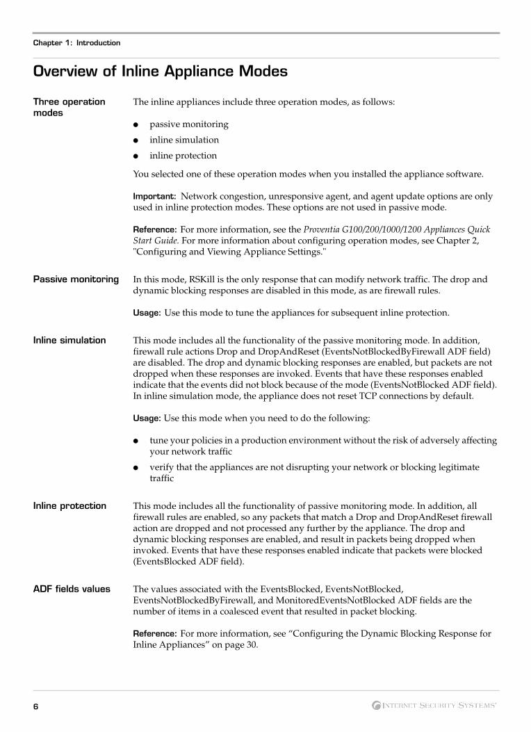
Three operation modes
The inline appliances include three operation modes, as follows:
● passive monitoring
● inline simulation
● inline protection
You selected one of these operation modes when you installed the appliance software.
Important: Network congestion, unresponsive agent, and agent update options are only used in inline protection modes. These options are not used in passive mode.
Reference: For more information, see the Proventia G100/200/1000/1200 Appliances Quick Start Guide. For more information about configuring operation modes, see Chapter 2, "Configuring and Viewing Appliance Settings."
Passive monitoring In this mode, RSKill is the only response that can modify network traffic. The drop and dynamic blocking responses are disabled in this mode, as are firewall rules.
Usage: Use this mode to tune the appliances for subsequent inline protection.
Inline simulation This mode includes all the functionality of the passive monitoring mode. In addition, firewall rule actions Drop and DropAndReset (EventsNotBlockedByFirewall ADF field) are disabled. The drop and dynamic blocking responses are enabled, but packets are not dropped when these responses are invoked. Events that have these responses enabled indicate that the events did not block because of the mode (EventsNotBlocked ADF field). In inline simulation mode, the appliance does not reset TCP connections by default.
Usage: Use this mode when you need to do the following:
● tune your policies in a production environment without the risk of adversely affecting your network traffic
● verify that the appliances are not disrupting your network or blocking legitimate traffic
Inline protection This mode includes all the functionality of passive monitoring mode. In addition, all firewall rules are enabled, so any packets that match a Drop and DropAndReset firewall action are dropped and not processed any further by the appliance. The drop and dynamic blocking responses are enabled, and result in packets being dropped when invoked. Events that have these responses enabled indicate that packets were blocked (EventsBlocked ADF field).
ADF fields values The values associated with the EventsBlocked, EventsNotBlocked, EventsNotBlockedByFirewall, and MonitoredEventsNotBlocked ADF fields are the number of items in a coalesced event that resulted in packet blocking.
Reference: For more information, see “Configuring the Dynamic Blocking Response for Inline Appliances” on page 30.
6

Overview of Inline Appliance Modes
Changing appliance modes
If you change from the passive monitoring mode to the inline simulation or inline protection mode, you must also change the network connections to your appliance. An appliance operating in passive monitoring mode requires a connection to a tap, hub, or SPAN port.
If you change from the inline simulation or the inline protection mode to the passive monitoring mode, you must also change the network connections to your appliance. An appliance operating in inline simulation or inline protection mode requires in-line connections.
Note: You must use the appliance configuration menu to change from passive monitoring mode to inline simulation or inline protection modes, and vice versa.
Reference: For more information about configuring operation modes, see Chapter 2, "Configuring and Viewing Appliance Settings."
7Proventia G Intrusion Prevention Appliances User Guide

Chapter 1: Introduction
Setting Up a Local Configuration Interface and Logging In
Introduction Before you can view or change appliance settings, you must set up a local configuration interface and log in to the appliance.
How to setup a local configuration interface and log in
To set up a local configuration interface and log in to the appliance:
1. Do one of the following:
■ Connect a keyboard and monitor to the connectors on the rear panel of the appliance.
■ Connect a computer (such as a laptop) to the serial port on the appliance using the serial cable provided. Using a program such as Hyperterminal™, create a connection to the appliance with the following settings:
– Bits per second = 9600
– Data bits = 8
– Parity = None
– Stop bits = 1 (8-N-1)
– Flow control = None
– Communications Port = com port to which you have connected the appliance.
2. Set up Terminal Emulation = VT-100. Settings may vary, depending on the program you are using. In Hyperterminal, do the following:
■ Go to File Properties Settings.
■ Select Terminal Emulation = VT100.
■ Click OK.
3. Press the power button to start the appliance.
The appliance displays the login prompt: <appliance name> login: _
4. Type admin, and then press ENTER.
5. Type the admin password, and then press ENTER.
Note: The default password is admin.
An introductory screen appears.
6. Press ENTER.
The Configuration menu appears.
7. Use the UP and DOWN arrow keys to move from one menu item to another.
8. Press ENTER to select a menu item.
9. Configure the appliance’s settings as described in Chapter 2, “Configuring and Viewing Appliance Settings” on page 9.
8

Chapter 2
Configuring and Viewing Appliance
Settings
Overview
Introduction This chapter describes how to change appliance settings, view appliance settings, and configure appliance software.
In this chapter This chapter contains the following topics:
Topic Page
Changing the Administrative Password 10
Changing the Network Configuration Settings 11
Changing the Host Configuration Settings 12
Changing the Agent Name 13
Changing the Link Speed and Duplex Mode Settings 14
Changing the Date and Time Settings 15
Changing the Time Zone Setting 16
Viewing Appliance Settings 17
Viewing the Status of Appliance Components 18
Restarting the Agent 19
Allowing SiteProtector Access to the Appliance 20
Backing Up and Restoring the Appliance 22
Shutting Down or Rebooting the Appliance 23
Logging Out of the Local Configuration Interface 24
9Proventia G Intrusion Prevention Appliances User Guide

Chapter 2: Configuring and Viewing Appliance Settings
Changing the Administrative Password
Introduction You can change the administrative password at any time.
Caution: Record and protect this password. If you lose the password, you must reinstall the appliance.
Changing the adminitrative password
To change the administrative password:
1. Set up a local configuration interface and log in, as described in “Setting Up a Local Configuration Interface and Logging In” on page 8.
2. On the Configuration menu, select Change Admin Password, and then press ENTER.
3. Type the old password, and then press ENTER.
Note: The default password is admin.
4. Type the new password, and then press ENTER.
Note: You must use a minimum of six characters.
5. Retype the new password to confirm it, and then press ENTER.
The appliance displays a confirmation screen.
6. Press ENTER.
The Configuration menu appears.
10

Changing the Network Configuration Settings
Changing the Network Configuration Settings
Introduction You can change the following network configuration settings that you configured when you installed the appliance:
● IP address
● subnet mask
● gateway
Changing network settings
To change the network configuration settings:
1. Set up a local configuration interface and log in, as described in “Setting Up a Local Configuration Interface and Logging In” on page 8.
2. On the Configuration menu, select Change Network Configuration, and then press ENTER.
The Network Configuration screen appears.
3. Type the IP Address, Subnet Mask, and Gateway, using dotted-decimal notation.
Note: This IP address is used to manage the appliance through SSH and SiteProtector.
4. Press ENTER.
The appliance displays a progress message while it configures the host settings, and then displays the message Network configuration has been saved when the configuration is complete.
5. Press ENTER.
The Configuration menu appears.
11Proventia G Intrusion Prevention Appliances User Guide

Chapter 2: Configuring and Viewing Appliance Settings
Changing the Host Configuration Settings
Introduction You can change the following host configuration settings that you configured when you installed the appliance:
● hostname (required)
● domain name (recommended)
● name server (recommended)
Note: The appliance uses domain names and DNS information to send Email and SNMP responses. If you do not provide this information now, the appliance can still send Email and SNMP responses. You must specify the IP address of the appliance's mail server when you define the Email response on the management console. The appliance must have network access to the mail server.
Reference: For more information, see the management console's user documentation.
Changing the host configuration
To change the host configuration settings:
1. Set up a local configuration interface and log on, as described in “Setting Up a Local Configuration Interface and Logging In” on page 8.
2. On the Configuration menu, select Change Host Configuration, and then press ENTER.
The Host Configuration screen appears.
3. Type the Hostname (required), Domain Name, and Name Server, using dotted-decimal notation.
4. Press ENTER.
A confirmation screen appears.
5. Press ENTER.
The Configuration menu appears.
12

Changing the Agent Name
Changing the Agent Name
Introduction You can change the agent name that you configured when you installed the appliance.
Note: This is the name that appears for this appliance in your management interface. ISS recommends that you select a name that corresponds to the appliance’s geographic location, business unit, building address, or some other meaningful classification.
Changing the agent name
To change the agent name:
1. Set up a local configuration interface and log in, as described in “Setting Up a Local Configuration Interface and Logging In” on page 8.
2. On the Configuration menu, select Change Agent Name, and then press ENTER.
The Agent Name Configuration screen appears.
3. Change the agent name, and then press ENTER.
Note: If this agent is registered with a SiteProtector console, you must unregister it from the console and register it again after the appliance completes the name change.
4. Type y.
The appliance stops the agent, changes the name, restarts the agent, and then a confirmation screen appears.
Note: Typing n returns to the Configuration menu.
5. Press ENTER.
The Configuration menu appears.
Configuring agent options
You can configure how the driver processes traffic if an agent becomes unresponsive or during an agent update. If an agent is not responding, then it is not monitoring and protecting the network. You can configure the agent to pass all traffic (fail open to traffic) or drop all traffic (fail closed to traffic) when it is not responding. Options are as follows:
● maintain link and forward traffic
● maintain link and drop traffic
● do not maintain link
13Proventia G Intrusion Prevention Appliances User Guide

Chapter 2: Configuring and Viewing Appliance Settings
Changing the Link Speed and Duplex Mode Settings
Introduction You can change the link speed and duplex mode settings that you configured when you installed the appliance.
Setting duplex and link speed
To improve appliance performance, choose link speed and duplex mode settings to match your environment. If you are not sure which settings are correct for your environment, choose Auto/Auto.
Exception: The default Auto/Auto settings are correct for all environments except for 100 Full Duplex and 10 Full Duplex. You must specifically select the duplex mode and link speed applicable for these environments, as follows:
● 100 Full Duplex–select Full Duplex mode and link speed 100 Mbps
● 10 Full Duplex–select Full Duplex mode and link speed 10 Mbps
Appliances and link speed
G appliance models G100, G200, and G1000 have two ports labeled A and B. The G1200 appliance has eight ports labeled A through H. You can configure link speed and duplex mode settings appropriate for the appliance you have installed
Changing the link speed and duplex mode settings
To change the link speed and duplex mode settings:
1. Set up a local configuration interface and log in, as described in “Setting Up a Local Configuration Interface and Logging In” on page 8.
2. On the Configuration menu, select Change Port Link Settings, and then press ENTER.
The Port Link Configuration screen appears.
3. Select Port A, and then press the SPACE BAR to select the duplex mode and port link speed.
4. Select Port B, and press the SPACE BAR to select the duplex mode and port link speed.
Note: If you are configuring a G1200 appliance, repeat Steps 1 and 2 to select additional ports.
5. Press ENTER.
The Configuration menu appears.
14

Changing the Date and Time Settings
Changing the Date and Time Settings
Introduction You can change the date and time settings that you configured when you installed the appliance.
Changing the date and time settings
To change the date and time settings:
1. Set up a local configuration interface and log in, as described in “Setting Up a Local Configuration Interface and Logging In” on page 8.
2. On the Configuration menu, select Change Time/Date Settings, and then press ENTER.
The Date/Time Configuration menu appears.
3. Select Set Date and Time.
4. Type the new date, and then press ENTER.
Note: Use the format [MM/DD/YYYY].
5. Type the new time, and then press ENTER.
Note: Use the format [HH:MM:SS] and a 24-hour clock.
A confirmation screen appears.
6. Press ENTER.
The Configuration menu appears.
15Proventia G Intrusion Prevention Appliances User Guide

Chapter 2: Configuring and Viewing Appliance Settings
Changing the Time Zone Setting
Introduction You can change the time zone settings for the appliance.
Changing the time zone
To change the time zone setting:
1. Set up a local configuration interface and log in, as described in “Setting Up a Local Configuration Interface and Logging In” on page 8.
2. On the Configuration menu, select Change Time/Date Settings, and then press ENTER.
The Date/Time Configuration menu appears.
3. Select Set Time Zone.
4. Select the continent or ocean in which the appliance is located, and then press ENTER.
5. Select the country in which the appliance is located, and then press ENTER.
6. Select the region in which the appliance is located, and then press ENTER.
Note: This screen does not appear if the country you selected contains only one region (time zone).
7. Type y.
The Configuration menu appears.
16

Viewing Appliance Settings
Viewing Appliance Settings
Introduction You can view the settings that you configured during the appliance installation:
● the IP address, subnet mask, and gateway of the appliance management interface
● the hostname, domain name, and name server (if provided during initial installation) of the appliance
● the operation mode
● the current date, time, and time zone settings of the appliance
● the appliance’s serial number
Viewing settings To view the settings:
1. Set up a local configuration interface and log on, as described in “Setting Up a Local Configuration Interface and Logging In” on page 8.
2. On the Configuration menu, select Proventia G Series Information, and then press ENTER.
Information about the appliance appears.
3. Press ESC.
The Configuration menu appears.
17Proventia G Intrusion Prevention Appliances User Guide

Chapter 2: Configuring and Viewing Appliance Settings
Viewing the Status of Appliance Components
Introduction You can view the status and version of the agent and daemon components of the appliance.
Viewing the status of the appliance components
To view the status of the appliance components:
1. Set up a local configuration interface and log in, as described in “Setting Up a Local Configuration Interface and Logging In” on page 8.
2. On the Configuration menu, select Agent Status, and then press ENTER.
The appliance displays the following items:
■ status of the agent
■ status of the daemon
■ version of the agent
■ version of the daemon
■ event collector IP address
■ event collector name
Note: The event collector fields appear only if the appliance is configured to communicate with the event collector.
3. View the information, and then type n.
The Configuration menu appears.
18

Restarting the Agent
Restarting the Agent
Introduction You may want to restart the agent to troubleshoot a problem with the appliance.
Restarting the agent
To restart the agent:
1. Set up a local configuration interface and log in, as described in “Setting Up a Local Configuration Interface and Logging In” on page 8.
2. On the Configuration menu, select Agent Status, and then press ENTER.
The appliance displays the following items:
■ status of the agent
■ status of the daemon
■ version of the agent
■ version of the daemon
3. Type y.
The agent restarts, and then a confirmation screen appears.
Note: Typing n returns to the Configuration menu.
4. Press ENTER.
The Configuration menu appears.
19Proventia G Intrusion Prevention Appliances User Guide
Chapter 2: Configuring and Viewing Appliance Settings
Allowing SiteProtector Access to the Appliance
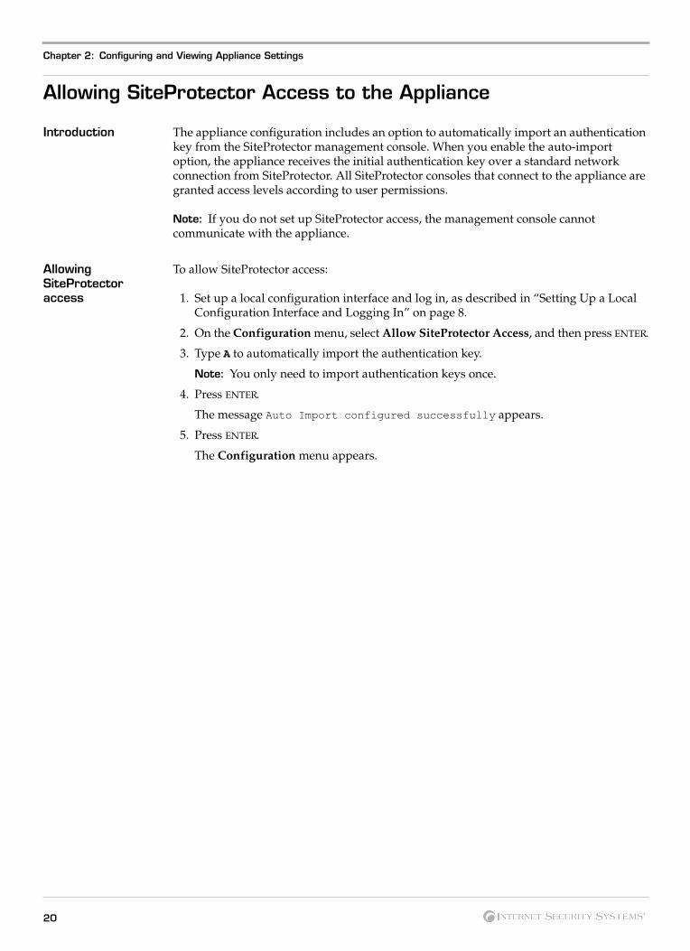
Introduction The appliance configuration includes an option to automatically import an authentication key from the SiteProtector management console. When you enable the auto-import option, the appliance receives the initial authentication key over a standard network connection from SiteProtector. All SiteProtector consoles that connect to the appliance are granted access levels according to user permissions.
Note: If you do not set up SiteProtector access, the management console cannot communicate with the appliance.
Allowing SiteProtector access
To allow SiteProtector access:
1. Set up a local configuration interface and log in, as described in “Setting Up a Local Configuration Interface and Logging In” on page 8.
2. On the Configuration menu, select Allow SiteProtector Access, and then press ENTER.
3. Type A to automatically import the authentication key.
Note: You only need to import authentication keys once.
4. Press ENTER.
The message Auto Import configured successfully appears.
5. Press ENTER.
The Configuration menu appears.
20

Applying Updates in SiteProtector
Applying Updates in SiteProtector
Introduction By default, the SiteProtector update mechanism intermittently checks the main ISS Web site (https://www.iss.net) for the latest XML file. This XML file contains information regarding all available product updates. When a new update is indicated, SiteProtector updates the database with the relevant information so that the SiteProtector console displays a new update is available. By default, the latest XML file is downloaded every 24 hours.
Important: ISS strongly recommends that you configure your system and create a system backup before installing an update.
Applying an update To apply service release update to the appliance from SiteProtector:
1. In Siteprotector, the Available Update column displays "Yes" when an update is available.
2. Right-click on the G appliance name.
3. Select "Apply update" and follow the instructions as prompted.
The update installs remotely.
21Proventia G Intrusion Prevention Appliances User Guide
Chapter 2: Configuring and Viewing Appliance Settings
Backing Up and Restoring the Appliance
Introduction This topic explains how to back up and restore the appliance configuration settings. It includes procedures for the following tasks:
Backing up and restoring appliance settings
To back up and restore the appliance configuration settings:
1. Set up a local configuration interface and log in, as described in “Setting Up a Local Configuration Interface and Logging In” on page 8.
2. On the Configuration menu, select Backup/Restore G Series, and then press ENTER.
The Backup/Restore Menu screen appears.
3. Select from one of the following options:
■ Backup Current Configuration
■ Restore Config From Backup
■ Restore to Factory Default
Note: The Restore to Factory Default option preserves current host, network, time zone, and password settings.
4. Press ENTER.
22

Shutting Down or Rebooting the Appliance
Shutting Down or Rebooting the Appliance
Introduction You can shut down or reboot the appliance using the local configuration interface.
Shutting down and restarting the appliance
To shut down or restart the appliance:
1. Set up a local configuration interface and log in, as described in “Setting Up a Local Configuration Interface and Logging In” on page 8.
2. On the Configuration menu, select Shutdown/Reboot and then press ENTER.
3. Do one of the following:
■ To reboot the appliance, type R.
The appliance reboots and displays the Login prompt.
■ To shut down the appliance, type S.
The appliance shuts down and displays a message when it is safe for you to turn off the power.
23Proventia G Intrusion Prevention Appliances User Guide
Chapter 2: Configuring and Viewing Appliance Settings
Logging Out of the Local Configuration Interface
Introduction Log out of the local configuration interface when you are finished viewing or changing the appliance's settings.
Logging out To log out of the local configuration interface:
● On the Configuration menu, select Logout, and then press ENTER.
The appliance displays the Login prompt.
24

Chapter 3
Configuring Responses, Rules, and
Policies
Overview
Introduction This chapter describes how to configure responses, rules, and policies for the appliance.
In this chapter This chapter contains the following topics:
Topic Page
Configuring the RSKILL Response 26
Working with the Dynamic Blocking Table 28
Configuring the Dynamic Blocking Response for Inline Appliances 30
Configuring the Drop Response for Inline Appliances 32
Customizing Firewall Rules 33
Configuring the Operation Mode 36
Changing Inline Appliance Modes 37
Configuring Packet Captures 38
Customizing the No Packet Alert 40
Changing the Port ID Value 42
25Proventia G Intrusion Prevention Appliances User Guide
Chapter 3: Configuring Responses, Rules, and Policies
Configuring the RSKILL Response
Introduction You can use the RSKill response to prevent unauthorized hosts or networks from connecting to services on the monitored computer. When the appliance detects an attack, it terminates or resets the connection to the targeted computer. You can configure the kill interface for the RSKill response from the local configuration interface or from the management console.
Note: You do not have to configure the RSKill response for a G intrusion prevention appliance that is operating in inline protection mode or inline simulation mode. The default behavior for RSKILL in Inline Protection mode is to drop the attack packet in addition to sending TCP resets on the connection. This is similar to the new DROP ConnectionWithReset response.
Reference: For more information about the RSKill response, see the online Help. Look up the “About the RSKILL Response” topic. For more information about the drop response, see “Configuring the Drop Response for Inline Appliances” on page 32.
Procedure To configure the RSKill response:
1. Set up a local configuration interface and log in, as described in “Setting Up a Local Configuration Interface and Logging In” on page 8.
2. On the Configuration menu, select Configure RSKill, and then press ENTER.
The RSKill Configuration screen appears.
3. Do you want to configure the kill interface?
■ If yes, type y, and then go to Step 4.
■ If no, type n.
4. Do you want to use a DHCP server?
■ If yes, press the SPACE BAR to select DHCP.
■ If no, type the static addresses in the IP Address, Subnet Mask, and Gateway.
Caution: Verify the IP addresses before you begin. Entering an incorrect IP address can disable remote management. The IP address must be an available IP address on a network segment. This IP address is needed to obtain the MAC address of the Gateway. Once the appliance has the MAC address of the Gateway, this temporary IP address is no longer needed.
Tip: To move from one field to the next, press TAB.
Note: The RSKill response occurs in stealth mode. The appliance uses these static network addresses to determine the gateway MAC address. If the appliance cannot determine the MAC address, then you must manually enter the address on the next screen.
5. Press ENTER.
The appliance saves the settings, and then attempts to determine the gateway MAC address.
26

Configuring the RSKILL Response
6. Did the appliance determine its MAC address?
■ If yes, press ENTER.
■ If no, type the MAC address.
Note: If you do not know the MAC address, contact your system administrator.
7. Press ENTER.
The Configuration menu appears.
27Proventia G Intrusion Prevention Appliances User Guide

Chapter 3: Configuring Responses, Rules, and Policies
Working with the Dynamic Blocking Table
Introduction This topic describes how to work with the dynamic blocking table. It includes procedures for the following tasks:
● viewing the table
● clearing the table
● deleting table rules
● saving the table to a file
Rules stored in the table
The dynamic blocking table stores the rules created when the dynamic blocking response is enabled in the Policy Editor. The table assigns a unique number or Rule ID for each rule listed in the table.
Reference: For more information about configuring dynamic blocking and setting blocking criteria, see “Configuring the Dynamic Blocking Response for Inline Appliances” on page 30 and the online Help. Look up the “Configuring Dynamic Blocking for Inline Appliances” topic.
Viewing the table To view the dynamic blocking table:
1. Set up a local configuration interface and log in, as described in “Setting Up a Local Configuration Interface and Logging In” on page 8.
2. On the Configuration menu, select Dynamic Blocking Table, and then press ENTER.
The Dynamic Blocking menu appears.
3. Select Display Table.
The Dynamic Blocking Table and a list of rules appear.
Note: If you have deployed a network sensor in your environment and the sensor is stopped, rules do not appear in the table.
4. Type R to refresh the table.
5. Press ESC.
The Dynamic Blocking menu appears.
Clearing the table To clear the dynamic blocking table:
1. Set up a local configuration interface and log in, as described in “Setting Up a Local Configuration Interface and Logging In” on page 8.
2. On the Configuration menu, select Dynamic Blocking Table, and then press ENTER.
The Dynamic Blocking menu appears.
3. Select Clear Table.
4. Type y.
The appliance clears the table, and then a confirmation screen appears.
Note: Typing n returns to the Dynamic Blocking menu.
5. Press ENTER.
The Dynamic Blocking menu appears.
28
Working with the Dynamic Blocking Table
Deleting table rules To delete table rules:
1. Set up a local configuration interface and log in, as described in “Setting Up a Local Configuration Interface and Logging In” on page 8.
2. On the Configuration menu, select Dynamic Blocking Table, and then press ENTER.
The Dynamic Blocking menu appears.
3. Select Delete Table Rules.
4. Select the Rule ID to delete.
5. Press ENTER.
The Dynamic Blocking menu appears.
Saving the table to a file
To save the table to a file:
1. Set up a local configuration interface and log in, as described in “Setting Up a Local Configuration Interface and Logging In” on page 8.
2. On the Configuration menu, select Dynamic Blocking Table, and then press ENTER.
The Dynamic Blocking menu appears.
3. Select Save Table to File.
4. Type a file name for the table.
5. Press ENTER.
The Dynamic Blocking menu appears.
29Proventia G Intrusion Prevention Appliances User Guide

Chapter 3: Configuring Responses, Rules, and Policies
Configuring the Dynamic Blocking Response for Inline Appliances
Introduction The inline appliance uses the dynamic blocking response to block traffic that meets certain criteria for a period of time after an attack.
Important: Dynamic blocking is available only for inline modes. Packets are blocked only in inline protection mode.
Dynamic blocking criteria
The dynamic blocking criteria are as follows:
● victim address
● victim port
● intruder address
● intruder port
● ICMP code
● ICMP type
When the appliance detects an attack, and the dynamic blocking response is enabled for the signature in the active policy, the appliance blocks any subsequent packets that meet the same criteria as specified in the response. Dynamic blocking criteria are predefined in the inline appliance Attack Blocker policy.
Note: Internet Control Message Protocol (ICMP) is used by gateway or destination host to communicate with a source host, for example, to report an error in datagram processing. Usually, gateways communicate between themselves using Gateway to Gateway Protocol (GGP) for control purposes. ICMP Type and ICMP Code help to identify why the message was sent.
Dynamic blocking specifications
You can specify the duration in seconds and the percentage of packets blocked for each event that uses the dynamic blocking response. You set the dynamic blocking specifications on the SiteProtector management console, in the Policy Editor window.
Dynamic blocking example
If victim address is selected as the criteria, and IP address xxx.xx.xx.x is initially attacked on the TCP protocol, all subsequent TCP traffic to this IP address will be blocked for the specified blocking duration. When the duration expires, the blocking response ends.
Dynamic blocking table
Rules created when you enable dynamic blocking are stored in a dynamic blocking table.
Reference: For more information, see “Working with the Dynamic Blocking Table” on page 28.
Configuring dynamic blocking specifications
To configure dynamic blocking specifications:
1. In the SiteProtector Site Manager, select the appliance.
2. Open the Policy Editor.
3. In the Policy Editor window, select the signature for which you want to configure dynamic blocking specifications.
4. Select the Dynamic Blocking Response tab.
30
Configuring the Dynamic Blocking Response for Inline Appliances
5. Select the check box for the Response Type, as follows:
■ BlockIntruder (blocks unauthorized access attacks)
■ BlockWorm (blocks self-replicating viruses)
■ IsolateTrojan (isolates malicious code that is contained inside apparently harmless code)
Note: The criteria for the selected response type appears on this tab, but you cannot change the criteria from the Policy Editor window.
6. Do you want to change the duration for which packets will be blocked?
■ If yes, type the number of seconds in the Duration (Secs) field.
■ If no, go to Step 7.
7. Do you want to change the percentage of packets that will be blocked?
■ If yes, type the percentage in the Percentage Blocked field.
■ If no, go to Step 8.
Note: ISS recommends that you set the blocking percentage to 100% to ensure that the appliance properly blocks attacks.
8. From the File menu, select Save.
A confirmation message appears.
9. Click OK.
10. From the File menu, select Close.
Viewing events To view events generated with dynamic blocking enabled:
1. In the SiteProtector SiteManager, select the Sensor Analysis tab.
A list of events appears.
2. Select an event, and then right-click it.
3. Select View event details.
The Event Details window appears.
4. In the Attribute Name, locate the ADF event as follows:
■ “Response Name DYNAMIC BLOCK” indicates the dynamic blocking response configuration.
■ “EventsBlocked” the event resulted in one or more packets being blocked.
■ “EventsNotBlocked” no blocking was performed because the appliance was in inline simulation mode.
■ “EventsNotBlockedByFirewall” the inline appliance is in simulation mode, so packets that matched a Drop or DropAndReset action are processed normally. Events generated by this processing have this field.
■ “MonitoredEventsNotBlocked” a firewall rule with the “Monitor” action matched this packet, so blocking responses (drop and dynamic block) do not result in the packet being dropped.
■ “InlineApplianceMode” indicates the current mode of the inline appliance.
5. Click OK to close the window.
31Proventia G Intrusion Prevention Appliances User Guide
Chapter 3: Configuring Responses, Rules, and Policies
Configuring the Drop Response for Inline Appliances
Introduction The inline appliance uses the drop response to drop the connection in which an event occurs or the packet that triggered the event.
Drop response options
The drop response includes the following options:
● “ConnectionWithReset” drops all packets on the connection in which the event occurred and sends a TCP reset packet(s).
● “Connection” drops all packets on the connection in which the event occurred.
● “Packet” drops the packet that triggered the event.
Event details You can view event details in SiteProtector to determine if the drop response was used for an event. If the response was used, DROP is the Attribute Name, and the Drop option is the Attribute Value.
ISS recommendations
The ISS recommended drop response, if any, is indicated with an asterisk.
ISS recommends that you to use ConnectionWithReset instead of Connection whenever possible. Doing so ensures that the TCP connection is closed and that no packets on the connection are allowed through the inline appliance in protection mode. If Connection is specified, then no packets on the connection are allowed though, but the TCP packets are resent, which increases network traffic.
32

Customizing Firewall Rules
Customizing Firewall Rules
Introduction This topic describes how to customize firewall rules so that a policy matches your security plan needs. It includes procedures for the following tasks:
● enabling or disabling firewall rules functionality
● adding a firewall rule
● removing a firewall rule
● adding a firewall rule statement
● editing a firewall rule statement
● removing a firewall rule statement
● enabling or disabling specific rules
Firewall guidelines The following guidelines apply to firewalls:
● Firewall rules are available for inline appliances only.
● You cannot customize a pre-defined policy. Changes to pre-defined policies can only be made from derived policies.
● When appropriate, using firewall rules is preferred over the use of packet filters and connection events, to help improve the efficiency of the appliance.
Reference: For more information, see Appendix A, "Firewall Rules".
Enabling or disabling firewall rules functionality
To enable or disable firewall rules functionality:
1. In the Policy Editor window, select the Firewall Rules tab.
2. Do you want to enable firewall rules functionality?
■ If yes, select the Firewall Rules check box.
■ If no, go to Step 3.
3. Do you want to disable a rule?
■ If yes, clear the Firewall Rules check box.
■ If no, you are finished.
Adding a firewall rule
To add a firewall rule:
1. In the Policy Editor window, select the Firewall Rules tab.
2. Click Add.
The Enter a name window appears.
3. Type the name of the rule, and then click OK.
The rule is added.
4. Do you want to enable logging for this rule?
■ If yes, select Log.
■ If no, clear the Log option.
33Proventia G Intrusion Prevention Appliances User Guide

Chapter 3: Configuring Responses, Rules, and Policies
5. Select an action from for the firewall rule from the Action list. Valid actions are as follows:
■ “Ignore” allows the packet through and does not process it any further.
■ “Monitor” processes the packet; the drop and dynamic blocking responses do not drop the packet. Acts as an IP whitelist.
■ “Protect” processes the packet normally (as instructed by the policy).
■ “Drop” drops the packet that matches the firewall rule.
■ “DropAndReset” drops the packet and resets the connection.
6. Add statements to the firewall rule. See the “Adding a firewall rule statement” procedure.
7. From the File menu, click Save.
A confirmation message appears.
8. Click OK.
9. From the File menu, click Close.
Removing a firewall rule
To remove a firewall rule:
1. In the Policy Editor window, select the Firewall Rules tab.
2. Select a rule in the right-hand pane, and then click Remove.
The rule is removed.
3. From the File menu, click Save.
A confirmation message appears.
4. Click OK.
5. From the File menu, click Close.
Adding a firewall rule statement
To add a firewall rule statement:
1. In the Policy Editor window, select the Firewall Rules tab.
2. Select a rule, and then click Add Statement.
The Add New Firewall Statement window appears.
3. Using the examples and information provided in the window, type the rule statement in the Statement Text field.
4. Click OK.
If the statement contains errors, the Syntax Error window appears.
5. Did the Syntax Error window appear?
■ If yes, go to Step 6.
■ If no, go to Step 8.
6. Locate the column in the statement that contains the error.
The column number that contains the error is indicated in the Syntax Error window as Column: X. Additionally, a carat ^ below the line of text points to the error.
7. Correct the error(s), and then click OK.
8. Repeat Steps 1 through 7 for each statement you want to add to the rule.
34

Customizing Firewall Rules
Editing a firewall rule statement
To edit a firewall rule statement:
1. In the Policy Editor window, select the Firewall Rules tab.
2. Select a rule.
The rule statements appear in the right-hand pane.
3. Select a rule statement, and then click Edit.
The Edit Firewall Statement window appears.
4. Repeat Steps 2 through 7 in the “Adding a Firewall Statement” procedure.
Removing a firewall rule statement
To remove a firewall rule statement:
1. In the Policy Editor window, select the Firewall Rules tab.
2. Select a rule.
The rule statements appear in the right-hand pane.
3. Select a rule statement, and then click Delete.
A confirmation message appears.
4. Click Yes.
The statement is removed.
Enabling or disabling specific rules
To enable or disable specific firewall rules:
1. In the Policy Editor window, select the Firewall Rules tab.
2. Do you want to enable a rule?
■ If yes, select the check box for the rule.
■ If no, go to Step 3.
3. Do you want to disable a rule?
■ If yes, clear the check box for the rule.
■ If no, you are finished.
Apply the policy After you customize the firewall rules, you must apply the policy to the appliance. For more information, see the online Help. Look up “Working with Proventia Appliance Policies.”
35Proventia G Intrusion Prevention Appliances User Guide

Chapter 3: Configuring Responses, Rules, and Policies
Configuring the Operation Mode
Introduction You can change the operation mode that you configured when you installed the appliance.
Reference: For more information about operation modes, see “Overview of Inline Appliance Modes” on page 6. For more information about installing the appliance, see the Proventia G100/200/1000/1200 Appliances Quick Start Guide.
Connecting the network cables
Connect the network cables to correspond with the operation mode you plan to use for the appliance.
● Use the management interface to connect the appliance to the network you will use to manage it. On the back of the appliance, there are 2 additional ports labeled as 1 and 2, for a total of 4 ports. Use port 1 for the management interface and port 2 for the kill interface.
● Connect the network cables to correspond with the operation mode (passive or inline) you plan to use for the appliance.
● Use the kill interface to connect the appliance to the network for sending the RSKill response for events (passive mode only).
For passive mode, use detection port A to connect to one hub, switch SPAN port, or tap. The appliance still aggregates full-duplex traffic with a full-duplex tap set up to use both ports A and B. Do not use the cable and coupler.
Note: In passive mode, the appliance can monitor a total of one segment despite the existence of 2 ports (A and B).
● For inline simulation or inline protection mode, connect a one-foot cable and crossover coupler from detection port A to a network hub/switch. Connect a cable from port B to another hub/switch.
Note: Before you start the appliance, determine whether network traffic is passing through the appliance. If traffic passes through, then the hardware configuration is completed. If traffic does not pass through, remove the crossover coupler and plug that network cable directly into port A. For more information, see the Readme located on the ISS Download Center site at http://www.iss.net/download/.
Changing the operation mode
To change the operation mode:
1. Set up a local configuration interface and log in, as described in “Setting Up a Local Configuration Interface and Logging In” on page 8.
2. On the Configuration menu, select Agent Mode, and then press ENTER.
The Mode Configuration screen appears.
3. Select an operating mode by pressing the SPACE BAR. Available modes are as follows:
■ Inline Protection
■ Inline Simulation
■ Passive Monitoring
4. Press ENTER.
The Configuration menu appears.
36

Changing Inline Appliance Modes
Changing Inline Appliance Modes
Introduction You can change the operation mode of inline appliances on the General tab of the Inline Appliance Properties window.
Changing from passive monitoring mode to inline modes
You cannot change from passive monitoring mode to inline simulation or inline protection modes, or vice versa, using this procedure. You must use the appliance configuration menu instead.
Reference: For more information, see “Overview of Inline Appliance Modes” on page 6 and “Configuring the Operation Mode” on page 36.
Changing inline appliance modes
To change inline appliance modes:
1. In the SiteProtector Site Manager, select the appliance.
2. In the Inline Appliance Properties window, select the General tab.
3. In the Inline Appliance Mode area, select the mode from the list.
4. Click OK.
37Proventia G Intrusion Prevention Appliances User Guide

Chapter 3: Configuring Responses, Rules, and Policies
Configuring Packet Captures
Introduction Proventia G appliances can capture attack packets that you can view and analyze from the SiteProtector management console. The system associates these captured packets with specific events, which can benefit a forensic investigation. You configure packet captures on the SiteProtector management console.
Configuring packet captures
To configure packet captures, you must first set the LOGDB response in the Policy Editor to the LogwithRaw response name. The LOGDB response displays the detected event on the monitoring console. Together with the Display response, raw data from the LogWithRaw response is translated into a format that appears in the Event Details window on the management console. There are two packet capture files: FirstPacket.enc and LastPacket.enc. These packet capture files display as icons in the Event Details window, under the Attribute value.
Changing the capture buffer size
The default buffer size for capturing packets is 80 MB. In general, the capture buffer size does not need to be changed. See “Changing the Capture Buffer Size” on page 46.
Reference: For more information about using the Policy Editor, see the online Help. Look up “Working with Proventia Appliance Policies.”
Setting the LogwithRaw response
To set the LOGDB response to LogwithRaw:
1. In the SiteProtector Site Manager, select the appliance.
2. Select Apply Policy.
The Select Policy window opens.
3. Select the policy, and then click Derive New.
4. In the Policy Editor window, select the tab for the type of event to which you are assigning responses.
5. In the signature pane, click the signature to which you want to assign responses.
6. The response list in the right pane displays the responses that are currently assigned to this signature.
7. Select the check box next to the LOGDB response type.
8. Select the LogwithRaw response name.
9. From the File menu, select Save.
A confirmation message appears.
10. Click OK.
11. From the File menu, select Exit.
12. Select the policy, and then click OK.
The policy opens.
13. Verify that the policy is correct, and then click OK.
Viewing packet captures
To view packet captures:
1. In the SiteProtector SiteManager, select the Network Sensor Analysis tab.
A list of events by tag name appears.
38

Configuring Packet Captures
2. Select a row, and then right-click the tag name.
3. Select View Event Details.
The Event Details window appears.
4. View the Event Attribute Data pairs, and then look at the Attribute value.
An icon appears under the Attribute value to indicate that packet data has been captured.
5. Double-click the icon.
A text file appears in the right pane. This text file includes information about data in the packet, such as URLs, IP addresses, and cookies.
Note: When you scroll to a new event, the Help information returns to the right pane.
39Proventia G Intrusion Prevention Appliances User Guide

Chapter 3: Configuring Responses, Rules, and Policies
Customizing the No Packet Alert
Introduction The Proventia appliance can send an alert to the management console when the appliance is not analyzing traffic. Sending a no packet alert is beneficial in a reconfigured network that does not pass traffic to the appliance. The no packet alert also provides a quick and effective way to determine whether the appliance is properly monitoring traffic.
Reference: For more information about configuring the appliance, see the online Help. Look up the “Proventia Appliance No Packet Alert” topic.
Where configured You configure the no packet alert on the SiteProtector management console.
Default parameter settings
The no packet alert parameters are enabled by default in the management console. Under most circumstances, you do not need to reconfigure these parameter settings. However, you may want to customize the settings if the level of network activity is low. You may also want to change the interval at which the network measures traffic.
Settings correspond to adapters
No packet alert parameter settings correspond to the adapters, or ports, that receive traffic on the appliance. G100, G200, and G1000 appliances have two ports labeled A and B. The G1200 appliance has eight ports labeled A through H.
Note: The A series appliances (except for A201) have four ports labeled A, B, C, and D.
Audit events The parameters settings affect the Network_Quiet and Network_Normal audit events.
● The Network_Quiet event indicates that the level of network activity is unusually quiet. The packets per sampling interval has dropped below the configured low-water mark.
● The Network_Normal event indicates that the appliance is properly receiving traffic and the level of network activity has returned to normal.
Default parameters The following table describes the default parameters that support no packet alert on the Proventia appliance:
Name Value Description
traffic.sample true Enables traffic sampling to detect unusual levels of network activity. Affects the Network_Quiet and Network_Normal audit events.
traffic.sample.interval 300 seconds Determines the rate at which traffic flow is sampled, for the purpose of detecting abnormal levels of network activity. Affects the Network_Quiet and Network_Normal audit events.
adapter.A.low-water—
adapter.H.low-water
0 Indicates the minimum number of packets per traffic sampling interval expected on the adapter (A through H) on the appliance. If the packet rate falls below this threshold, the network issues a warning that network traffic is abnormally low. Low traffic can indicate a loss of network connectivity or a change in the sensor’s spanning port configuration.
Table 5: No packet alert parameters
40

Customizing the No Packet Alert
Customizing the no packet alert
Open the SiteProtector management console. Use the Advanced Parameters tab on the Sensor Properties window to view or customize no packet alert settings.
To customize the no packet alert:
1. In the SiteProtector grouping tree, select the group to which the appliance is assigned, and then select the Sensor tab in the right pane.
A list of sensors and appliances appears.
2. Right-click the appliance, and then select Inline Appliance.
3. Select Edit Properties.
The Sensor Properties window appears.
4. In the Sensor Properties window, select the Advanced Parameters tab.
5. Select the parameter name, and then click Edit.
The Advanced Value window appears.
6. Edit the value setting, and then click OK.
7. Repeat Steps 5 and 6 for each parameter you want to configure.
8. Click OK.
The Sensor Properties window appears.
adapter.A.high-water—
adapter.H.high-water
2 Indicates the number of packets per traffic sampling interval expected on the adapter (A through H) on the appliance. The network uses the high-water mark to prevent multiple low-traffic warnings when the traffic flow is hovering around the low-water mark. The network also uses the high-water mark as the threshold to issue the Network_Normal event.
Name Value Description
Table 5: No packet alert parameters
41Proventia G Intrusion Prevention Appliances User Guide
Chapter 3: Configuring Responses, Rules, and Policies
Changing the Port ID Value
Introduction The Proventia A and G appliances (except A201) can identify the specific port that detected an event. This enables you to identify the affected network segment. Identifying the port and network segment aids forensic investigation when up to four unrelated segments are monitored on one appliance.
Where configured You change the port ID value on the SiteProtector management console.
Port and adapter names
Ports on the back of the appliance correspond to a parameter setting for an adapter that is enabled on the management console. G100, G200, and G1000 appliances have two ports labeled A and B. The G1200 appliance has eight ports labeled A through H. The corresponding settings are adapter.A.name through adapter.H.name. Events detected by the adapter for a port appear in the Event Details window.
Note: The A series appliances have four ports, labeled A, B, C, and D.
Parameters settings for adapters
The parameter settings for the adapters are enabled by default in the management console. Under most circumstances, you do not need to change these parameters. However, you may want to customize the parameters if you change the name of the adapter or change the segment that the adapter is monitoring.
Changing the port ID value
Open the SiteProtector management console. Use the Advanced Parameters tab on the Sensor Properties window to view or change the port ID value.
To change the port ID value:
1. In the SiteManager grouping tree, select the group to which the appliance is assigned, and then select the Sensor tab in the right pane.
A list of sensors and appliances appears.
2. Right-click the appliance, and then select Network Sensor.
3. Select Edit Properties.
The Sensor Properties window appears.
4. In the Sensor Properties window, select the Advanced Parameters tab.
5. Select the adapter name, and then click Edit.
The Advanced Value window appears.
6. Change the adapter value for the port ID, and then click OK.
Example: If you want to change the adapter to correspond to a segment, the value A could change to Marketing Segment 3.
7. Repeat Steps 5 and 6 for each adapter name you want to change.
8. Click OK.
The Sensor Properties window appears.
42

Changing the Port ID Value
Viewing events generated for a port
To view events generated for a port:
1. In the SiteProtector SiteManager, select the Sensor Analysis tab.
A list of events appears.
2. Select an event, and then right-click it.
3. Select View event details.
The Event Details window appears.
4. In the Attribute Pair, locate the adapter name, and then locate the corresponding port ID.
5. Click Next to display the next alert, click OK to close the window.
43Proventia G Intrusion Prevention Appliances User Guide

Chapter 3: Configuring Responses, Rules, and Policies
44

Chapter 4
Configuring Advanced Settings
Overview
Introduction This chapter explains how to configure advance settings for the appliance.
Changing advanced settings
The appliance software includes advanced configuration settings that are intended to provide ISS Customer Support with additional troubleshooting options. You may need to change these settings to help resolve problems with the appliance software.
Caution: ISS recommends that you contact Technical Support before you change or reconfigure the advanced settings. Changing these settings may adversely affect the appliance operation if they are not properly configured.
In this chapter This chapter contains the following topics:
Topic Page
Changing the Capture Buffer Size 46
Configuring Network Congestion Options 47
Configuring Agent Options 49
45Proventia G Intrusion Prevention Appliances User Guide
Chapter 4: Configuring Advanced Settings
Changing the Capture Buffer Size
Introduction This topic describes how to change the capture buffer size.
Buffer sizes The default buffer size for the G1000 appliance is 80 MB. The buffer size for the G100 and G200 appliances is 100 MB. In general, you do not need to change the capture buffer size.
Important: ISS recommends that you contact Technical Support before you change the buffer size.
Changing capture buffer size
To change the capture buffer size:
1. Set up a local configuration interface and log in, as described in “Setting Up a Local Configuration Interface and Logging In” on page 8.
2. On the Configuration menu, select Advanced Settings, and then press ENTER.
The Warning screen appears.
3. Read the warning, and then type y.
The Advanced Settings menu appears.
4. Select Change Capture Buffer Size, and then press ENTER.
The Capture Buffer Configuration screen appears.
5. Change the buffer size, and then press ENTER.
The appliance saves the settings, and then a confirmation message appears.
6. Press ENTER.
The Advanced Settings menu appears.
46

Configuring Network Congestion Options
Configuring Network Congestion Options
Introduction This topic describes how to configure network congestion options.
Important: Network congestion options are only used in inline protection mode. These settings are not used in inline simulation mode or passive mode
When network congestion occurs
Network congestion can occur when bandwidth or traffic levels exceed supported limits.
Configuring network congestion options
You can configure how the agent processes traffic when the network is congested. Options are as follows:
● “Forward Traffic” forwards traffic without processing it, or fails open to traffic. When traffic levels return to normal, the agent resumes normal operation.
● “Drop Traffic” blocks some of the traffic without processing it, or fails closed to traffic. When traffic levels return to normal, the agent returns to normal operation.
● “No Action” does not compensate for network congestion. If the agent cannot process the traffic, the appliance may go into bypass mode for a short period on appliance models that have bypass cards (G100/G200/G1000C). The connection to the network may be lost for a short period of time on appliance models that do not have bypass cards (G1000F).
Note: ISS recommends that you use option one (if fail open to traffic is desired) or option two (if fail closed to traffic is desired) rather than option three. Options one and two allow the agent to return to normal operation more quickly.
Configuring network congestion options
To configure network congestion options:
1. Set up a local configuration interface and log in, as described in “Setting Up a Local Configuration Interface and Logging In” on page 8.
2. On the Configuration menu, select Advanced Settings, and then press ENTER.
The Warning screen appears.
3. Read the warning, and then type y.
The Advanced Settings menu appears.
4. Select Configure Network Congestion Options, and then press ENTER.
The Network Configure Options screen appears.
5. Select the driver behavior by pressing the SPACE BAR. Available options are as follows:
■ Forward Traffic
■ Drop Traffic
■ No Action
Reference: For more information, see “Configuring network congestion options” on page 47.
47Proventia G Intrusion Prevention Appliances User Guide

Chapter 4: Configuring Advanced Settings
6. Press ENTER.
The appliance saves the settings, and then a confirmation message appears.
7. Press ENTER.
The Advanced Settings menu appears.
48

Configuring Agent Options
Configuring Agent Options
Introduction This topic gives the procedures for configuring the following:
● the way the system processes traffic if an agent stops responding
● the way the driver behaves during an agent update
When an agent update occurs, the system applies policies, response policies, and micro X-Press Updates (XPUs) and updates appliance properties.
Important: Settings for unresponsive agents and agent updates apply only to inline protection mode. These settings are not used in inline simulation mode or passive mode.
Reference: For information about checking the status of an agent, see “Viewing the Status of Appliance Components” on page 18.
Agent options You can configure how the driver processes traffic if an agent becomes unresponsive or when an agent update occurs. If an agent is not responding, then it is not monitoring and protecting the network. You can configure the agent to pass all traffic (fail open to traffic) or drop all traffic (fail closed to traffic) when it is not responding or during an update. Options are as follows:
● Maintain Link and forward traffic
● Maintain Link and drop traffic
● Do not maintain link
Maintain Link and forward traffic
Maintain Link and forward traffic passes all traffic (fails open to traffic) if the agent becomes unresponsive or during an agent update. The driver continues to run during the time set (in seconds) for the Maintain Link Duration setting. The appliance passes all traffic.
Note: Appliance models that have bypass cards (G100/G200/G1000C) maintain the link differently than the appliances that operate in bypass mode. When an appliance that has a bypass card switches to bypass mode, links must be renegotiated. This may cause the network to stop responding for a short period of time. When you enable this option, the appliance does not go into bypass mode and the link remains active, eliminating unnecessary non-response time.
Maintain Link and drop traffic
Maintain Link and drop traffic does not pass traffic (fails closed to traffic) if the agent becomes unresponsive or during an agent update. The driver continues to run during the time set (in seconds) for the Maintain Link Duration option, but blocks all traffic received on the monitoring ports.
Note: ISS recommends using this option on appliance models that do not have bypass cards (G1000F) if you do not want the appliance to pass traffic (fail closed). Not maintaining the link may increase the amount of time the system is not responding on some networks because the link must be renegotiated.
Do not maintain link Do not maintain link causes the driver to exit and the link is not maintained. The appliance goes into bypass mode on models that have bypass cards (G100/G200/G1000C) when the agent is unresponsive (fails open to traffic) or during an agent update. During
49Proventia G Intrusion Prevention Appliances User Guide
Chapter 4: Configuring Advanced Settings
the switch to bypass mode, the link must be renegotiated. This may cause some networks to stop responding for a short period of time. ISS recommends using the Maintain Link and forward traffic option if you want the appliance to pass traffic (fail open).
On appliance models that do not have bypass cards (G1000F), the connection is lost to the network behind the appliance (fails closed) and the link is not maintained. This may cause problems for some network configurations. Not maintaining the link may increase the amount of time the system is not responding because the link must be renegotiated. ISS recommends using the Maintain Link and drop traffic option if you do not want the appliance to pass traffic (fail closed to traffic).
Maintain Link Duration setting
The Maintain Link Duration setting is 90 seconds. You can change this value for your network environment. If the agent is unresponsive or an update lasts for more than 90 seconds, set the Maintain Link duration to a larger value. If the agent remains unresponsive after the duration time passes, the driver exits. G100, G200, and G1000C appliances go into bypass mode when this happens. On appliance models that do not have bypass cards (G1000F), the connection is lost to the network behind the appliance.
Configuring unresponsive agent options
To configure unresponsive agent options:
1. Set up a local configuration interface and log in, as described in “Setting Up a Local Configuration Interface and Logging In” on page 8.
2. On the Configuration menu, select Advanced Settings, and then press ENTER.
The Warning screen appears.
3. Read the warning, and then type y.
The Advanced Settings menu appears.
4. Select Configure Unresponsive Agent Options, and then press ENTER.
The Unresponsive Agent Options screen appears.
5. Select the driver behavior by pressing the SPACE BAR. Available options are as follows:
■ Maintain Link and forward traffic
■ Maintain Link and drop traffic
■ Do not maintain the link
6. If needed, change the Maintain Link Duration setting.
7. Press ENTER.
The appliance saves the settings, and then a confirmation message appears.
8. Press ENTER.
9. The Advanced Settings menu appears.
Configuring agent update options
To configure agent update options:
1. Set up a local configuration interface and log in, as described in “Setting Up a Local Configuration Interface and Logging In” on page 8.
2. On the Configuration menu, select Advanced Settings, and then press ENTER.
The Warning screen appears.
3. Read the warning, and then type y.
The Advanced Settings menu appears.
50

Configuring Agent Options
4. Select Configure Agent Update Options, and then press ENTER.
The Agent Update Options screen appears.
5. Select the driver behavior by pressing the SPACE BAR. Available options are as follows:
■ Maintain Link and forward traffic
■ Maintain Link and drop traffic
■ Do not maintain the link
6. If needed, change the Maintain Link Duration setting.
7. Press ENTER.
The appliance saves the settings, and then a confirmation message appears.
8. Press ENTER.
The Advanced Settings menu appears.
51Proventia G Intrusion Prevention Appliances User Guide

Chapter 4: Configuring Advanced Settings
52

Chapter 5
Troubleshooting
Overview
Introduction This chapter describes troubleshooting techniques and includes the procedures for reinstalling the appliance software.
In this chapter This chapter contains the following topic:
Topic Page
Reinstalling the Appliance Software 54
Configuring Trace Options 59
Using the Setup.log File for Troubleshooting 61
53Proventia G Series Appliances User Guide

Chapter 5: Troubleshooting
Reinstalling the Appliance Software
Introduction You can use the Proventia G Intrusion Prevention Appliance Recovery CD to reinstall the appliance. The CD reinstalls the original, unconfigured software. To reinstall the software, you must complete the following procedures:
● reinstall the appliance
● log in and change the password
● configure the network and host
● configure the date and time
● configure the agent name
● configure the link speed and duplex mode settings
● configure the operation mode
● confirm passive monitoring mode
● configuring the RSKILL response
● apply settings and log out
● apply updates, as needed
Note: After rebooting with the recovery CD, the appliance reverts to the default login name and password.
Prerequisites Before you reconfigure the appliance, you must have completed the following prerequisites:
● Verify the IP address, subnet mask, and default gateway of the appliance’s management interface.
● Verify the hostname (required), domain name (recommended), and DNS name server (recommended) for the appliance.
● Verify that the appliance is operational. If your appliance is not operational, contact ISS Customer Support at [email protected].
Reinstalling the appliance
To reinstall the appliance:
1. If there is a bezel cover on the front of the appliance, remove it.
2. Place the Proventia Appliance Recovery CD in the CD-ROM drive.
3. Connect a computer or monitor and keyboard to the appliance.
Reference: For more information, see “Setting Up a Local Configuration Interface and Logging In” on page 8.
4. Reboot the appliance. See “Shutting Down or Rebooting the Appliance” on page 23.
Tip: You can manually turn the power off and on if the appliance is not responding.
The appliance reboots and reloads the operating system.
5. Type reinstall, and then press ENTER.
The appliance displays status messages, ejects the CD, and then reboots.
6. Go to “Logging in and changing the password,” next in this topic.
54

Reinstalling the Appliance Software
Logging in and changing the password
To log in and change the password:
1. When the appliance has rebooted, type admin at the unconfigured login prompt, and then press ENTER.
2. Type admin at the Password prompt, and then press ENTER.
The Proventia G Setup screen appears.
3. Press ENTER.
The Software License Agreement appears.
4. Read the Software License Agreement, and then type y to accept its terms.
The Change Password screen appears.
5. Type the old password, admin, and then type a new password.
Note: You must use a minimum of six characters.
6. Retype the new password to confirm it, and then press ENTER.
Note: Record and protect this password. If you lose or forget this password, you must reinstall the appliance.
7. Press ENTER.
The Network Configuration screen appears.
8. Go to “Configuring the network and host,” next in this topic.
Configuring the network and host
To configure the network and host:
1. Type the IP Address, Subnet Mask, and Gateway of the appliance’s management interface, and then press ENTER.
The appliance displays the message Network configured.
2. Press ENTER.
The Host Configuration screen appears.
3. Type the Hostname (required), Domain Name (recommended), and Name Server (recommended) for the appliance, and then press ENTER.
Note: The appliance uses domain names and DNS information to send Email and SNMP responses. If you do not provide this information now, then you must specify the IP address of the appliance’s mail server when you define the Email response on the management console. The appliance must have network access to the mail server. For more information, see the management console's user documentation.
The appliance displays a progress message while it configures the host settings, and then displays the message Host configuration has been saved when the configuration is complete.
4. Press ENTER.
The Timezone Configuration screen appears.
5. Go to “Configuring the date and time,” next in this topic.
Configuring the date and time
To configure the date and time at which events occur:
1. Select the continent or ocean in which the appliance is located, and then press ENTER.
2. Select the country in which the appliance is located, and then press ENTER.
55Proventia G Series Appliances User Guide

Chapter 5: Troubleshooting
3. Select the region in which the appliance is located, and then press ENTER.
Note: This screen does not appear if the country you selected contains only one time zone.
4. Type y to confirm, and then press ENTER.
The Date/Time Configuration screen appears.
5. Press ENTER to accept the Date and Time for the appliance, or type a new time and press ENTER.
Note: Use the format [HH:MM:SS] and a 24-hour clock.
The appliance displays the message Date and time set.
6. Press ENTER.
The Agent Name Configuration screen appears.
7. Go to “Configuring the agent name,” next in this topic.
Configuring the agent name
To configure the agent name:
1. Press ENTER to accept the default agent name, or type a specific name and then press ENTER.
Note: This is the asset name that appears for this appliance in your management interface. ISS recommends that you select a name that corresponds to the appliance’s geographic location, business unit, building address, or some other meaningful classification.
The appliance continues to apply your configuration settings. The status bar displays a message when the configuration ends.
2. Press ENTER.
The Port Link Configuration screen appears.
3. Go to “Configuring the link speed and duplex mode settings,” next in this topic.
Configuring the link speed and duplex mode settings
G appliance models G100, G200, and G1000 have two ports labeled A and B. The G1200 appliance has eight ports labeled A through H. You can configure link speed and duplex mode settings appropriate for the appliance you have installed.
To configure the link speed and duplex mode settings:
1. Select Port A, and then press the SPACE BAR to select the port link speed and duplex mode.
2. Select Port B, and then press the SPACE BAR to select the port link speed and duplex mode.
Note: If you are configuring a G1200 appliance, repeat Steps 1 and 2 to select additional ports.
3. Press ENTER.
The Mode Configuration screen appears.
4. Go to “Configuring the operation mode,” next in this topic.
56

Reinstalling the Appliance Software
Configuring the operation mode
To configure the operation mode:
1. Select an operation mode.
2. Press ENTER.
3. Do one of the following:
■ If you selected passive monitoring, the Mode Change Confirmation screen appears. Go to “Confirming passive monitoring mode” next in this topic.
■ If you selected protection or inline simulation, go to “Applying settings and logging out.”
Confirming passive monitoring mode
To confirm passive monitoring mode:
1. Do you want to confirm passive monitoring mode?
■ If yes, type y, and then go to Step 2.
■ If no, type n, and then select a different operation mode, as described in “Configuring the operation mode.”
2. Press ENTER, and then go to “Configuring the RSKILL response” next in this topic.
Configuring the RSKILL response
To configure the RSKILL response:
1. Do you want to configure the RSKill response?
■ If yes, type y, and then go to Step 2.
■ If no, type n, and then go to Step 1 in “Applying settings and logging out,” next in this topic.
Note: When the appliance detects an attack, the RSKill response terminates or resets the connection to the targeted computer.
2. Do you want to use a DHCP server?
■ If yes, press the SPACE BAR to select DHCP.
■ If no, type the static addresses in the IP Address, Subnet Mask, and Gateway.
Tip: To move from one field to the next, press TAB.
Note: The RSKill response occurs in stealth mode. The appliance uses these static network addresses to determine the gateway MAC address. If the appliance cannot determine the MAC address, then you must manually enter the address on the next screen.
3. Press ENTER.
The appliance attempts to determine and display the gateway MAC address.
4. Did the appliance determine its MAC address?
■ If yes, press ENTER.
■ If no, type the MAC address.
Note: If you do not know the MAC address, contact your system administrator.
5. Press ENTER.
The appliance continues to apply your configuration settings, and then displays a message when the configuration is complete.
6. Go to “Applying settings and logging out,” next in this topic.
57Proventia G Series Appliances User Guide

Chapter 5: Troubleshooting
Applying settings and logging out
To apply settings and log out:
1. Press ENTER.
The appliance displays a message that it will now log you off. You can log back in at any time to change configuration settings.
2. Press ENTER.
The login prompt appears.
58

Configuring Trace Options
Configuring Trace Options
Introduction This topic describes how to configure settings for trace files. Trace files provide ISS Customer Support with information used to troubleshoot problems. This topic includes procedures for the following tasks:
● configuring agent logging
● configuring communications logging
● configuring daemon logging
Configuring agent logging
To configure agent logging:
1. Set up a local configuration interface and log in, as described in “Setting Up a Local Configuration Interface and Logging In” on page 8.
2. On the Configuration menu, select Configure Trace Options, and then press ENTER.
The Trace Configuration screen appears.
3. Select Configure Agent Logging, and then press ENTER.
4. Type the trace level value and the trace file name, and the press ENTER.
The appliance saves the settings, and then a confirmation message appears.
5. Press ENTER.
The Trace Configuration menu appears.
Configuring communications logging
To configure communications logging:
1. Set up a local configuration interface and log in, as described in “Setting Up a Local Configuration Interface and Logging In” on page 8.
2. On the Configuration menu, select Configure Trace Options, and then press ENTER.
The Trace Configuration screen appears.
3. Select Configure Communications Logging, and then press ENTER.
4. Type the trace level value and the trace file name, and the press ENTER.
The appliance saves the settings, and then a confirmation message appears.
5. Press ENTER.
The Trace Configuration menu appears.
Configuring daemon logging
To configure daemon logging:
1. Set up a local configuration interface and log in, as described in “Setting Up a Local Configuration Interface and Logging In” on page 8.
2. On the Configuration menu, select Configure Trace Options, and then press ENTER.
The Trace Configuration screen appears.
3. Select Configure Daemon Logging, and then press ENTER.
59Proventia G Series Appliances User Guide

Chapter 5: Troubleshooting
4. Type the trace level value and the trace file name, and the press ENTER.
The appliance saves the settings, and then a confirmation message appears.
5. Press ENTER.
The Trace Configuration menu appears.
60
Using the Setup.log File for Troubleshooting
Using the Setup.log File for Troubleshooting
Introduction The setup.log file contains a record of every action that you perform using the Configuration menu. You can use this file to troubleshoot problems that may occur when you configure G appliances software.
File location The setup.log file is located in the following directories:
● /opt/ISS/appliance
● /opt/ISS/issSensors/network_sensor_1/Logs
You can download the setup.log file from the SiteProtector management console, in the same manner that you download trace logging files.
61Proventia G Series Appliances User Guide

Chapter 5: Troubleshooting
62

Appendix A
Firewall Rules
Overview
Introduction You can configure firewall rules to block attacks based on various source and destination information in the packet. You specify this information in rule statements.
In this appendix This appendix contains the following topics:
Topic Page
About Firewall Rules 64
Firewall Rules Language 66
Firewall Advanced Parameters 69
63Proventia G Intrusion Prevention Appliances User Guide

Appendix A: Firewall Rules
About Firewall Rules
Firewall actions The firewall currently supports several different actions that describe how the firewall reacts to the packets matched in the rules, or statements. These actions are defined as follows:
Ignore: Enables the matching packet pass through, so that no further actions or responses are taken on the packet. Operates in the same manner as the User Specified Packet Filter.
Protect: Enables matching packets to be processed by normal responses, such as (but not limited to) logging, the drop response (not to be confused with the drop firewall action), RealSecure Kills, and Dynamic Blocking.
Monitor: Functions as an IP whitelist. Applies to packets that match the statements bypass the Dynamic Blocking response, bypass the Drop response, and bypass the RSKill response. However, all other responses still apply to the packet.
Note: The monitor action bypasses RSKill by default. Setting the sensor.whitelistresets parameter to true (1) causes the RSKill response to fire when a packet matches the associated rule.
Drop: Drops the packets as they pass through the firewall. Because the firewall is inline, this action prevents the packets from reaching the target machine. To the person whose packet is dropped, it appears as if the target machine simply does not respond. The connection most likely makes several retry attempts, and then the connection eventually times out.
Drop and Reset: Functions in the same manner as the drop action, but sends a reset packet to the source machine. The connection terminates more quickly (because it is automatically reset) than with the drop response.
Rule ordering The firewall also pays strict attention to rule ordering. The list of rules displayed in the interface are read from top to bottom and applies actions as the rules are read.
If a packet comes across the network that matches a rule that has the Ignore action set, then the rest of the rules in the firewall are ignored (for that packet) when the action is executed. This gives the advantage of increased granularity in the rules. For example, use two statements to kill all connections coming into a network segment except those destined to a specific port on a specific host.
Adapter any IP src addr any dst addr xxx.xx.x.xx tcp dst port 80
(Action = “ignore”)
adapter any ip src addr any dst addr xxx.xx.x.1-xxx.x.x.255
(Action = “drop”)
The first rule allows all traffic to port 80 on the host xxx.xx.x.xx to pass right through as legitimate traffic to a web server. All other traffic on that network segment is dropped.
If you reversed the order of those two rules, all traffic to that segment is dropped, even traffic to the web server on xxx.xx.x.xx.
64

About Firewall Rules
You can change rule order by dragging the rules up or down in the right-hand window pane of the Firewall window.
Note: These rules can be applied to not only TCP traffic, but also to ICMP and UDP traffic. This allows you to effectively block (through the drop action) UDP connections.
Mode differences The firewall rules, as described, work only in inline modes. When the appliance is set to passive mode it works like a traditional sensor, and is not in the “direct path” of the packets. Therefore, the firewall rules are disabled in passive mode. However, traditional responses such as Email still work in all modes.
Network traffic is not affected when the appliance is in simulation mode.The Drop and DropAndReset firewall actions operate like Protect, with additional information in ADF fields in any events generated by these packets. The additional event information indicates that those packet(s) would have been dropped by the firewall if the sensor had been in protection mode. The EventsNotBlockedByFirewall action displays in the SiteProtector Console, Event Details window.
This is a good way to set up the appliance on a real network and not actually enable it. Packets still pass through, and the appliance describes what it would have done to your traffic had you enabled it.
65Proventia G Intrusion Prevention Appliances User Guide

Appendix A: Firewall Rules
Firewall Rules Language
Firewall rules language
The firewall rules language consists of the following components:
● rules
● statements
● clauses
● conditions
● expressions
Note: In the examples that follow, the clauses in brackets are optional.
Rules A firewall rule consists of several statements that define the traffic for which the rule applies.
Statements A firewall rule statement consists of an adapter clause followed by either an IP clause or an IP datagram clause or both.
Examples:
● [ adapter-clause ] IP-clause [ IP-datagram-clause ]
● [ adapter-clause ] [ IP-clause ] IP-datagram-clause
Clauses A clause consists of a keyword that identifies packet traffic direction on a adapter. The protocol and a number of conditions that are specific to that protocol follow the keyword. You may use each specific type of condition once per clause. You may, however, specify conditions in any order. Traffic matches a clause only if it matches all conditions in the clause.
Adapter Clause: The adapter clause indicates a specific adapter where the rule is applied. Supported adapter clauses are “any” or the letters A through H. If no adapter clause is specified, the rule matches packets on any adapter.
Examples:
● adapter A
● adapter B
● adapter any
IP Clause: The IP clause indicates the version of IP protocol and the conditions in the header that must be satisfied for the statement to match.
Examples:
● ip [ IP-source-address-condition ] [ IP-destination-address-condition ]
IP Datagram Clause: The IP datagram clause indicates the protocol and the protocol-specific conditions that must be satisfied for the statement to match. The supported protocols are ICMP, TCP, and UDP. You can also specify a set of IP protocol numbers.
66

Firewall Rules Language
Examples:
● icmp [ ICMP-type-condition ] [ ICMP-code-condition ]
● tcp [ TCP-source-port-number-condition ] [ TCP-destination-port-number-condition ]
● udp [ UDP-source-port-number-condition ] [ UDP-destination-port-number-condition ]
● proto protocol-number-expression
Conditions A condition consists of a keyword, which identifies the type of condition, followed by an expression that defines the condition.
IP Source and Destination Address Conditions: The source and destination address conditions indicate the set of allowable IP addresses for the source or the establishment of a TCP-based connection, UDP packet, or ICMP packet.
Examples:
● src addr IP-address-expression
● dst addr IP-address-expression
TCP/UDP Source and Destination Port Conditions: The source and destination port conditions indicate the set of TCP or UDP ports for the source or destination of the establishment of a (TCP) connection, or a (UDP) packet.
Examples:
● src port port-number-expression
● dst port port-number-expression
ICMP Type and Code Conditions: The ICMP message type and code conditions indicate the set of ICMP types or codes for either side of the packet.
Examples:
● type ICMP-type-expression
● code ICMP-code-expression
Expressions You can specify a single IP address or port to define a source and destination address and port conditions. Additionally, you can use ranges or any.
Using Ranges in Expressions: For IP addresses, port numbers, ICMP message types and codes, and protocol numbers, you can indicate a range of values using a dash (-) between the first and last values in the range.
Examples:
● ip src addr xxx.xxx.x.x - xxx.xxx.x.xx (where x is a number in the IP address)
● tcp dst port 20 – 80
67Proventia G Intrusion Prevention Appliances User Guide

Appendix A: Firewall Rules
Using 'any' in Expressions: You can specify 'any' in all expressions.
Examples:
● ip dst addr any
● icmp type any
Complete Examples The following statements are examples of complete firewall rules. If no protocol is specified, the rule assumes and uses “any” protocol.
● adapter A ip src addr xxx.xxx.x.x
(where x is a number in the IP address)
● adapter A ip src addr xxx.xxx.x dst addr any tcp src port 20 dst port 80
(where x is a number in the IP address)
● adapter any ip src addr any dst addr xxx.xxx.xx.x● adapter any ip src addr any dst addr any icmp type 8
● tcp● adapter B icmp● udp
68

Firewall Advanced Parameters
Firewall Advanced Parameters
Introduction This topic describes the advanced parameters used to tune firewall rules.
List of name/value pairs
The following table describes the name/value pairs and includes the default value for each pairs.
Name Description Field Type/Values
Default Value
firewalllog.enabled Determines whether firewall logging is enabled. If this parameter is set to True, details of packets that match a static firewall rule will be logged, only if logging for that specific rule is also enabled. If firewalllog.enabled is set to False, nothing will be logged.
boolean True
firewalllog.fileprefix String prepended to each file name in the firewall log. This should include the directory for the firewall log files and a name prefix.
string ./Logs/Fwlog
firewalllog.filesuffix String appended to the name of each file name in the firewall log.
string .txt
firewalllog.maxfiles The maximum number of files in the firewall log. number 20
firewalllog.maxKbytes
The maximum size of a file in the firewall log in kilobytes.
number 10,000
Table 6: Firewall Advanced Parameters
69Proventia G Intrusion Prevention Appliances User Guide

Appendix A: Firewall Rules
70

Index
link speed and duplex mode settings 56
aadding a firewall rule 33adding a firewall rule statement 33–34ADF eventsEventsBlocked 31EventsNotBlocked 31EventsNotBlockedByFirewall 31InlineApplianceMode 31MonitoredEventsNotBlocked 31Response Name DYNAMIC BLOCK 31
ADF fields 6administrative password 10advanced settings
contacting Technical Support 45agent name 13, 56agent options 49appliance
defined 2logging out 58
audit eventsNetwork_Normal 40Network_Quiet 40
bbacking up and restoring 22buffer size 38, 46
cchanging
appliance modes 7, 57capture buffer size 46date and time settings 15host configuration settings 12link speed and duplex mode settings 14network configuration settings 11passwords 10, 55time zone settings 16
configure settings for trace files 59configuring
agent name 13, 56agent options 49
Proventia G Intrusion Prevention Appliances User Guide
network and host 55network congestion options 47operation mode 57settings for trace files 59
confirmingpassive monitoring mode 57
conventions, typographicalin commands viiin procedures viiin this manual vii
customizingfirewall rules 33no packet alert settings 41
ddate and time
changing settings for 15DHCP server 26, 57documentation, locating vidomain names 12, 17, 55drop response 4, 6dynamic blocking response 30dynamic blocking table 28
clearing 28deleting table rules 29saving the table to a file 29viewing 28
eediting a firewall rule statement 33, 35Email responses 12, 55enabling or disabling firewall rules functionality 33enabling or disabling specific firewall rules 33
ffails closed to traffic 49fails open to traffic 49firewall rule
adding 33
71

Index
removing 34firewall rule statement
adding 34editing 35removing 35
ggateway MAC address 26, 57
hhardware
installing the appliance in a rack 2host configuration
changing 12hostname 17
iinstalling the appliance 2Internet Control Message Protocol (ICMP) 30Internet Security Systems
technical support viiiWeb site viii
llicense key
installing 2purchasing 2
local configuration interfaceconnecting a computer 8connecting a keyboard and monitor 8
LOGDB response 38
mMAC address 26, 57management console 2
user documentation 2managing appliances
with SiteProtector 2
nnetwork configuration
changing 11network congestion options 47
72
oonline Help
for SiteProtector 2operation modes
configuring 36definitions 6
pparameters
support for no packet alert 40passive monitoring mode
confirming 57passwords
administrative 10changing 10, 55minimum requirements 55
Policy Editor 38pre-installed software 2Proventia Appliance Recovery CD 54
qQuick Start Guide 2
rreinstalling the appliance 55
applying settings and logging out 58configuring
date and time 55configuring the agent name and RSKILL response 56configuring the network and host 55logging in and changing the password 55required procedures 54
removing a firewall rule 33–34removing a firewall rule statement 33restarting the agent 19RSKILL response v, 26, 54, 56–57rule statements
for firewalls 34rules
dynamic blocking table 28
ssetup.log file 61shutting down or rebooting the appliance 23SiteProtector

Index
Help 2importing authentication keys 20
SNMP responses 12, 55stealth mode 26, 57
ttechnical support, Internet Security Systems viiitime zone
setting for the appliance location 16trace files
configuring 59typographical conventions vii
uupdates, applying 21
vviewing appliance components 18viewing appliance settings
current date 17hostname 17IP address, subnet mask, and gateway 17name server 17time and time zone 17
viewing events 2viewing the dynamic blocking table 28
wWeb site, Internet Security Systems viii
Proventia G Intrusion Prevention Appliances User Guide
73
Index
74

Internet Security Systems, Inc. Software License AgreementTHIS SOFTWARE PRODUCT IS PROVIDED IN OBJECT CODE AND IS LICENSED, NOT SOLD. BY INSTALLING, ACTIVATING, COPYING OR OTHERWISE USING THIS SOFTWARE PRODUCT, YOU AGREE TO ALL OF THE PROVISIONS OF THIS SOFTWARE LICENSE AGREEMENT (“LICENSE”). IF YOU ARE NOT WILLING TO BE BOUND BY THIS LICENSE, RETURN ALL COPIES OF THE SOFTWARE PRODUCT AND LICENSE KEYS TO ISS WITHIN FIFTEEN (15) DAYS OF RECEIPT FOR A FULL REFUND OF ANY PAID LICENSE FEE. IF THE SOFTWARE PRODUCT WAS OBTAINED BY DOWNLOAD, YOU MAY CERTIFY DESTRUCTION OF ALL COPIES AND LICENSE KEYS IN LIEU OF RETURN.License - Upon payment of the applicable fees, Internet Security Systems, Inc. (“ISS”) grants to you as the only end user (“Licensee”) a nonex-clusive and nontransferable, limited license for the accompanying ISS software product and the related documentation (“Software”) and the associated license key(s) for use only on the specific network configuration, for the number and type of devices, and for the time period (“Term”) that are specified in ISS’ quotation and Licensee’s purchase order, as accepted by ISS. ISS limits use of Software based upon the number of nodes, users and/or the number and type of devices upon which it may be installed, used, gather data from, or report on, depending upon the specific Software licensed. A device includes any network addressable device connected to Licensee’s network, including remotely, including but not limited to personal computers, workstations, servers, routers, hubs and printers. A device may also include ISS hardware delivered with pre-installed Software and the license associated with such shall be a non-exclusive, nontransferable, limited license to use such pre-installed Software only in conjunction with the ISS hardware with which it is originally supplied and only during the usable life of such hardware. Except as provided in the immediately preceding sentence, Licensee may reproduce, install and use the Software on multiple devices, provided that the total number and type are authorized by ISS. Licensee acknowledges that the license key provided by ISS may allow Licensee to reproduce, install and use the Software on devices that could exceed the number of devices licensed hereunder. Licensee shall implement appropriate safeguards and controls to prevent loss or disclosure of the license key and unauthorized or unlicensed use of the Software. Licensee may make a reasonable number of backup copies of the Software and the associated license key solely for archival and disaster recovery purposes. In connection with certain Software products, ISS licenses security content on a subscription basis for a Term and provides Licensee with a license key for each such subscription. Content subscriptions are licensed pursuant to this License based upon the number of protected nodes or number of users. Security content is regularly updated and includes, but is not limited to, Internet content (URLs) and spam signatures that ISS classifies, security algorithms, checks, decodes, and ISS’ related analysis of such information, all of which ISS regards as its confidential information and intellectual property. Security content may only be used in conjunction with the applicable Software in accordance with this License. The use or re-use of such content for commercial purposes is prohibited. Licensee’s access to the security content is through an Inter-net update using the Software. In addition, unknown URLs may be automatically forwarded to ISS through the Software, analyzed, classified, entered in to ISS’ URL database and provided to Licensee as security content updates at regular intervals. ISS’ URL database is located at an ISS facility or as a mirrored version on Licensee’s premises. Any access by Licensee to the URL database that is not in conformance with this License is prohibited. Upon expiration of the security content subscription Term, unless Licensee renews such content subscription, Licensee shall implement appropriate system configuration modifications to terminate its use of the content subscription. Upon expiration of the license Term, Licensee shall cease using the Software and certify return or destruction of it upon request. Migration Utilities – For Software ISS markets or sells as a Migration Utility, the following shall apply. Provided Licensee holds a valid license to the ISS Software to which the Migration Utility relates (the “Original Software”), ISS grants to Licensee as the only end user a nonexclusive and nontransferable, limited license to the Migration Utility and the related documentation (“Migration Utility”) for use only in connection with Lic-ensee’s migration of the Original Software to the replacement software, as recommended by ISS in the related documentation. The Term of this License is for as long as Licensee holds a valid license to the applicable Original Software. Licensee may reproduce, install and use the Migra-tion Utility on multiple devices in connection with its migration from the Original Software to the replacement software. Licensee shall implement appropriate safeguards and controls to prevent unlicensed use of the Migration Utility. Licensee may make a reasonable number of backup cop-ies of the Migration Utility solely for archival and disaster recovery purposes. Third-party Products - Use of third party product(s) supplied hereunder, if any, will be subject solely to the manufacturer’s terms and conditions that will be provided to Licensee upon delivery. ISS will pass any third party product warranties through to Licensee to the extent authorized. If ISS supplies Licensee with Crystal Decisions Runtime Software, then the following additional terms apply: Licensee agrees not to alter, disas-semble, decompile, translate, adapt or reverse-engineer the Runtime Software or the report file (.RPT) format, or to use, distribute or integrate the Runtime Software with any general-purpose report writing, data analysis or report delivery product or any other product that performs the same of similar functions as Crystal Decisions’ product offerings; Licensee agrees not to use the Software to create for distribution a product that converts the report file (.RPT) format to an alternative report file format used by any general-purpose report writing, data analysis or report delivery product that is not the property of Crystal Decisions; Licensee agrees not to use the Runtime Software on a rental or timesharing basis or to operate a service bureau facility for the benefit of third–parties unless Licensee first acquires an Application Service Provider License from Crystal Decisions; Licensee may not use the Software or Runtime Software by itself or as part of a system to regularly deliver, distribute or share Reports outside of the Runtime Software environment: (a) to more than fifty (50) end users directly, or (b) to a location that is accessible to more than 50 end users without obtaining an additional license from Crystal Decisions; CRYSTAL DECISIONS AND ITS SUPPLIERS DIS-CLAIM ALL WARRANTIES, EXPRESS, OR IMPLIED, INCLUDING WITHOUT LIMITATION THE WARRANTIES OF MERCHANTABILITY, FIRNESS FOR A PARTICULAR PURPOSE, AND NONINFRINGEMENT OF THIRD PARTY RIGHTS. CRYSTAL DECISIONS AND ITS SUP-PLIERS SHALL HAVE NO LIABILITY WHATSOEVER UNDER THIS AGREEMENT OR IN CONNECTION WITH THE SOFTWARE. In this section 3 “Software” means the Crystal Reports software and associated documentation supplied by ISS and any updates, additional modules, or additional software provided by Crystal Decisions in connection therewith; it includes Crystal Decisions’ Design Tools, Report Application Server and Runtime Software, but does not include any promotional software of other software products provided in the same package, which shall be governed by the online software license agreements included with such promotional software or software product. Beta License – If ISS is providing Licensee with the Software, security content and related documentation as a part of an alpha or beta test, the following terms of this Section 4 additionally apply and supercede any conflicting provisions herein or any other license agreement accompany-ing, contained or embedded in the subject Beta Software or any associated documentation. ISS grants to Licensee a nonexclusive, nontrans-ferable, limited license to use the ISS alpha/prototype software program, security content, if any, and any related documentation furnished by ISS (“Beta Software”) for Licensee’s evaluation and comment (the “Beta License”) during the Test Period. ISS’ standard test cycle, which may be extended at ISS’ discretion, extends for sixty (60) days, commencing on the date of delivery of the Beta Software (the “Test Period”). Upon expiration of the Test Period or termination of the License, Licensee shall, within thirty (30) days, return to ISS or destroy all copies of the Beta Software, and shall furnish ISS written confirmation of such return or destruction upon request. Licensee will provide ISS information reason-ably requested by ISS regarding Licensee’s experiences with the installation and operation of the Beta Software. Licensee agrees that ISS shall have the right to use, in any manner and for any purpose, any information gained as a result of Licensee’s use and evaluation of the Beta Soft-ware. Such information shall include but not be limited to changes, modifications and corrections to the Beta Software. Licensee grants to ISS a perpetual, royalty-free, non-exclusive, transferable, sublicensable right and license to use, copy, make derivative works of and distribute any report, test result, suggestion or other item resulting from Licensee’s evaluation of its installation and operation of the Beta Software. If Licensee is ever held or deemed to be the owner of any copyright rights in the Beta Software or any changes, modifications or corrections to the Beta Software, then Licensee hereby irrevocably assigns to ISS all such rights, title and interest and agrees to execute all documents necessary to implement and confirm the letter and intent of this Section. Licensee acknowledges and agrees that the Beta Software (including its existence, nature and specific features) constitute Confidential Information as defined in Section 18. Licensee further agrees to treat as Confidential Infor-mation all feedback, reports, test results, suggestions, and other items resulting from Licensee’s evaluation and testing of the Beta Software as contemplated in this Agreement. With regard to the Beta Software, ISS has no obligation to provide support, maintenance, upgrades, modifica-tions, or new releases. However, ISS agrees to use its reasonable efforts to correct errors in the Beta Software and related documentation within a reasonable time, and will provide Licensee with any corrections it makes available to other evaluation participants. The documentation relating to the Beta Software may be in draft form and will, in many cases, be incomplete. Owing to the experimental nature of the Beta Soft-ware, Licensee is advised not to rely exclusively on the Beta Software for any reason. LICENSEE AGREES THAT THE BETA SOFTWARE

AND RELATED DOCUMENTATION ARE BEING DELIVERED “AS IS” FOR TEST AND EVALUATION PURPOSES ONLY WITHOUT WAR-RANTIES OF ANY KIND, INCLUDING WITHOUT LIMITATION ANY IMPLIED WARRANTY OF NONINFRINGEMENT, MERCHANTABILITY OR FITNESS FOR A PARTICULAR PURPOSE. LICENSEE ACKNOWLEDGES AND AGREES THAT THE BETA SOFTWARE MAY CON-TAIN DEFECTS, PRODUCE ERRONEOUS AND UNINTENDED RESULTS AND MAY AFFECT DATA NETWORK SERVICES AND OTHER MATERIALS OF LICENSEE. LICENSEE’S USE OF THE BETA SOFTWARE IS AT THE SOLE RISK OF LICENSEE. IN NO EVENT WILL ISS BE LIABLE TO LICENSEE OR ANY OTHER PERSON FOR DAMAGES, DIRECT OR INDIRECT, OF ANY NATURE, OR EXPENSES INCURRED BY LICENSEE. LICENSEE’S SOLE AND EXCLUSIVE REMEDY SHALL BE TO TERMINATE THE BETA SOFTWARE LICENSE BY WRITTEN NOTICE TO ISS. Evaluation License - If ISS is providing Licensee with the Software, security content and related documentation on an evaluation trial basis at no cost, such license Term is 30 days from installation, unless a longer period is agreed to in writing by ISS. ISS recommends using Software and security content for evaluation in a non-production, test environment. The following terms of this Section 5 additionally apply and supercede any conflicting provisions herein. Licensee agrees to remove or disable the Software and security content from the authorized platform and return the Software, security content and documentation to ISS upon expiration of the evaluation Term unless otherwise agreed by the parties in writ-ing. ISS has no obligation to provide support, maintenance, upgrades, modifications, or new releases to the Software or security content under evaluation. LICENSEE AGREES THAT THE EVALUATION SOFTWARE, SECURITY CONTENT AND RELATED DOCUMENTATION ARE BEING DELIVERED “AS IS” FOR TEST AND EVALUATION PURPOSES ONLY WITHOUT WARRANTIES OF ANY KIND, INCLUDING WITHOUT LIMITATION ANY IMPLIED WARRANTY OF NONINFRINGEMENT, MERCHANTABILITY OR FITNESS FOR A PARTICULAR PURPOSE. IN NO EVENT WILL ISS BE LIABLE TO LICENSEE OR ANY OTHER PERSON FOR DAMAGES, DIRECT OR INDIRECT, OF ANY NATURE, OR EXPENSES INCURRED BY LICENSEE. LICENSEE’S SOLE AND EXCLUSIVE REMEDY SHALL BE TO TERMINATE THE EVALUATION LICENSE BY WRITTEN NOTICE TO ISS. Covenants - ISS reserves all intellectual property rights in the Software, security content and Beta Software. Licensee agrees: (i) the Software, security content or Beta Software is owned by ISS and/or its licensors, is a valuable trade secret of ISS, and is protected by copyright laws and international treaty provisions; (ii) to take all reasonable precautions to protect the Software, security content or Beta Software from unautho-rized access, disclosure, copying or use; (iii) not to modify, adapt, translate, reverse engineer, decompile, disassemble, or otherwise attempt to discover the source code of the Software, security content or Beta Software; (iv) not to use ISS trademarks; (v) to reproduce all of ISS’ and its licensors’ copyright notices on any copies of the Software, security content or Beta Software; and (vi) not to transfer, lease, assign, sublicense, or distribute the Software, security content or Beta Software or make it available for time-sharing, service bureau, managed services offering, or on-line use. Support and Maintenance – Depending upon what maintenance programs Licensee has purchased, ISS will provide maintenance, during the period for which Licensee has paid the applicable maintenance fees, in accordance with its prevailing Maintenance and Support Policy that is available at http://documents.iss.net/maintenance_policy.pdf. Any supplemental Software code or related materials that ISS provides to Lic-ensee as part of any support and maintenance service are to be considered part of the Software and are subject to the terms and conditions of this License, unless otherwise specified. Limited Warranty - The commencement date of this limited warranty is the date on which ISS furnishes to Licensee the license key for the Soft-ware. For a period of ninety (90) days after the commencement date or for the Term (whichever is less), ISS warrants that the Software or secu-rity content will conform to material operational specifications described in its then current documentation. However, this limited warranty shall not apply unless (i) the Software or security content is installed, implemented, and operated in accordance with all written instructions and doc-umentation supplied by ISS, (ii) Licensee notifies ISS in writing of any nonconformity within the warranty period, and (iii) Licensee has promptly and properly installed all corrections, new versions, and updates made available by ISS to Licensee. Furthermore, this limited warranty shall not apply to nonconformities arising from any of the following: (i) misuse of the Software or security content, (ii) modification of the Software or secu-rity content, (iii) failure by Licensee to utilize compatible computer and networking hardware and software, or (iv) interaction with software or firmware not provided by ISS. If Licensee timely notifies ISS in writing of any such nonconformity, then ISS shall repair or replace the Software or security content or, if ISS determines that repair or replacement is impractical, ISS may terminate the applicable licenses and refund the applicable license fees, as the sole and exclusive remedies of Licensee for such nonconformity. THIS WARRANTY GIVES LICENSEE SPE-CIFIC LEGAL RIGHTS, AND LICENSEE MAY ALSO HAVE OTHER RIGHTS THAT VARY FROM JURISDICTION TO JURISDICTION. ISS DOES NOT WARRANT THAT THE SOFTWARE OR THE SECURITY CONTENT WILL MEET LICENSEE’S REQUIREMENTS, THAT THE OPERATION OF THE SOFTWARE OR SECURITY CONTENT WILL BE UNINTERRUPTED OR ERROR-FREE, OR THAT ALL SOFTWARE OR SECURITY CONTENT ERRORS WILL BE CORRECTED. LICENSEE UNDERSTANDS AND AGREES THAT THE SOFTWARE AND THE SECURITY CONTENT ARE NO GUARANTEE AGAINST UNSOLICITED E-MAILS, UNDESIRABLE INTERNET CONTENT, INTRU-SIONS, VIRUSES, TROJAN HORSES, WORMS, TIME BOMBS, CANCELBOTS OR OTHER SIMILAR HARMFUL OR DELETERIOUS PRO-GRAMMING ROUTINES AFFECTING LICENSEE’S NETWORK, OR THAT ALL SECURITY THREATS AND VULNERABILITIES, UNSOLICITED E-MAILS OR UNDESIRABLE INTERNET CONTENT WILL BE DETECTED OR THAT THE PERFORMANCE OF THE SOFT-WARE AND SECURITY CONTENT WILL RENDER LICENSEE’S SYSTEMS INVULNERABLE TO SECURITY BREACHES. THE REMEDIES SET OUT IN THIS SECTION 8 ARE THE SOLE AND EXCLUSIVE REMEDIES FOR BREACH OF THIS LIMITED WARRANTY. Warranty Disclaimer - EXCEPT FOR THE LIMITED WARRANTY PROVIDED ABOVE, THE SOFTWARE AND SECURITY CONTENT ARE EACH PROVIDED “AS IS” AND ISS HEREBY DISCLAIMS ALL WARRANTIES, BOTH EXPRESS AND IMPLIED, INCLUDING IMPLIED WARRANTIES RESPECTING MERCHANTABILITY, TITLE, NONINFRINGEMENT, AND FITNESS FOR A PARTICULAR PURPOSE. LIC-ENSEE EXPRESSLY ACKNOWLEDGES THAT NO REPRESENTATIONS OTHER THAN THOSE CONTAINED IN THIS LICENSE HAVE BEEN MADE REGARDING THE GOODS OR SERVICES TO BE PROVIDED HEREUNDER, AND THAT LICENSEE HAS NOT RELIED ON ANY REPRESENTATION NOT EXPRESSLY SET OUT IN THIS LICENSE. Proprietary Rights - ISS represents and warrants that ISS has the authority to license the rights to the Software and security content that are granted herein. ISS shall defend and indemnify Licensee from any final award of costs and damages against Licensee for any actions based on infringement of any U.S. copyright, trade secret, or patent as a result of the use or distribution of a current, unmodified version of the Software and security content, but only if ISS is promptly notified in writing of any such suit or claim, and only if Licensee permits ISS to defend, compro-mise, or settle same, and only if Licensee provides all available information and reasonable assistance. The foregoing is the exclusive remedy of Licensee and states the entire liability of ISS with respect to claims of infringement or misappropriation relating to the Software and security content. Limitation of Liability - ISS’ ENTIRE LIABILITY FOR MONETARY DAMAGES ARISING OUT OF THIS LICENSE SHALL BE LIMITED TO THE AMOUNT OF THE LICENSE FEES ACTUALLY PAID BY LICENSEE UNDER THIS LICENSE, PRORATED OVER A THREE-YEAR TERM FROM THE DATE LICENSEE RECEIVED THE SOFTWARE. OR SECURITY CONTENT, AS APPLICABLE, IN NO EVENT SHALL ISS BE LIABLE TO LICENSEE UNDER ANY THEORY INCLUDING CONTRACT AND TORT (INCLUDING NEGLIGENCE AND STRICT PROD-UCTS LIABILITY) FOR ANY SPECIAL, PUNITIVE, INDIRECT, INCIDENTAL OR CONSEQUENTIAL DAMAGES, INCLUDING, BUT NOT LIMITED TO, COSTS OF PROCUREMENT OF SUBSTITUTE GOODS OR SERVICES, DAMAGES FOR LOST PROFITS, LOSS OF DATA, LOSS OF USE, OR COMPUTER HARDWARE MALFUNCTION, EVEN IF ISS HAS BEEN ADVISED OF THE POSSIBILITY OF SUCH DAM-AGES. Termination - Licensee may terminate this License at any time by notifying ISS in writing. All rights granted under this License will terminate immediately, without prior written notice from ISS, at the end of the term of the License, if not perpetual. If Licensee fails to comply with any pro-visions of this License, ISS may immediately terminate this License if such default has not been cured within ten (10) days following written notice of default to Licensee. Upon termination or expiration of a license for Software, Licensee shall cease all use of such Software, including Software pre-installed on ISS hardware, and destroy all copies of the Software and associated documentation. Termination of this License shall

not relieve Licensee of its obligation to pay all fees incurred prior to such termination and shall not limit either party from pursuing any other rem-edies available to it. General Provisions - This License, together with the identification of the Software and/or security content, pricing and payment terms stated in the applicable ISS quotation and Licensee purchase order (if applicable) as accepted by ISS, constitute the entire agreement between the par-ties respecting its subject matter. Standard and other additional terms or conditions contained in any purchase order or similar document are hereby expressly rejected and shall have no force or effect. ISS Software and security content are generally delivered to Customer by supplying Customer with license key data. If Customer has not already downloaded the Software, security content and documentation, then it is available for download at http://www.iss.net/download/. All ISS hardware with pre-installed Software and any other products not delivered by download are delivered f.o.b. origin. This License will be governed by the substantive laws of the State of Georgia, USA, excluding the application of its conflicts of law rules. This License will not be governed by the United Nations Convention on Contracts for the International Sale of Goods, the application of which is expressly excluded. If any part of this License is found void or unenforceable, it will not affect the validity of the balance of the License, which shall remain valid and enforceable according to its terms. This License may only be modified in writing signed by an authorized officer of ISS. Notice to United States Government End Users - Licensee acknowledges that any Software and security content furnished under this License is commercial computer software and any documentation is commercial technical data developed at private expense and is provided with RESTRICTED RIGHTS. Any use, modification, reproduction, display, release, duplication or disclosure of this commercial computer software by the United States Government or its agencies is subject to the terms, conditions and restrictions of this License in accordance with the United States Federal Acquisition Regulations at 48 C.F.R. Section 12.212 and DFAR Subsection 227.7202-3 and Clause 252.227-7015 or applicable subsequent regulations. Contractor/manufacturer is Internet Security Systems, Inc., 6303 Barfield Road, Atlanta, GA 30328, USA. Export and Import Controls; Use Restrictions - Licensee will not transfer, export, or reexport the Software, security content, any related technol-ogy, or any direct product of either except in full compliance with the export controls administered by the United States and other countries and any applicable import and use restrictions. Licensee agrees that it will not export or reexport such items to anyone on the U.S. Treasury Depart-ment’s list of Specially Designated Nationals or the U.S. Commerce Department’s Denied Persons List or Entity List or such additional lists as may be issued by the U.S. Government from time to time, or to any country to which the United States has embargoed the export of goods (cur-rently Cuba, Iran, Iraq, Libya, North Korea, Sudan and Syria) or for use with chemical or biological weapons, sensitive nuclear end-uses, or mis-siles. Licensee represents and warrants that it is not located in, under control of, or a national or resident of any such country or on any such list. Many ISS software products include encryption and export outside of the United States or Canada is strictly controlled by U.S. laws and regula-tions. ISS makes its current export classification information available at http://www.iss.net/export. Please contact ISS’ Sourcing and Fulfillment for export questions relating to the Software or security content ([email protected]). Licensee understands that the foregoing obligations are U.S. legal requirements and agrees that they shall survive any term or termination of this License. Authority - Because the Software is designed to test or monitor the security of computer network systems and may disclose or create problems in the operation of the systems tested, Licensee and the persons acting for Licensee represent and warrant that: (a) they are fully authorized by the Licensee and the owners of the computer network for which the Software is licensed to enter into this License and to obtain and operate the Software in order to test and monitor that computer network; (b) the Licensee and the owners of that computer network understand and accept the risks involved; and (c) the Licensee shall procure and use the Software in accordance with all applicable laws, regulations and rules. Disclaimers - Licensee acknowledges that some of the Software and security content is designed to test the security of computer networks and may disclose or create problems in the operation of the systems tested. Licensee further acknowledges that neither the Software nor security content is fault tolerant or designed or intended for use in hazardous environments requiring fail-safe operation, including, but not limited to, air-craft navigation, air traffic control systems, weapon systems, life-support systems, nuclear facilities, or any other applications in which the failure of the Software and security content could lead to death or personal injury, or severe physical or property damage. ISS disclaims any implied warranty of fitness for High Risk Use. Licensee accepts the risk associated with the foregoing disclaimers and hereby waives all rights, reme-dies, and causes of action against ISS and releases ISS from all liabilities arising therefrom. Confidentiality - “Confidential Information” means all information proprietary to a party or its suppliers that is marked as confidential. Each party acknowledges that during the term of this Agreement, it will be exposed to Confidential Information of the other party. The obligations of the party (“Receiving Party”) which receives Confidential Information of the other party (“Disclosing Party”) with respect to any particular portion of the Disclosing Party’s Confidential Information shall not attach or shall terminate when any of the following occurs: (i) it was in the public domain or generally available to the public at the time of disclosure to the Receiving Party, (ii) it entered the public domain or became generally avail-able to the public through no fault of the Receiving Party subsequent to the time of disclosure to the Receiving Party, (iii) it was or is furnished to the Receiving Party by a third parting having the right to furnish it with no obligation of confidentiality to the Disclosing Party, or (iv) it was inde-pendently developed by the Receiving Party by individuals not having access to the Confidential Information of the Disclosing Party. Each party acknowledges that the use or disclosure of Confidential Information of the Disclosing Party in violation of this License could severely and irrep-arably damage the economic interests of the Disclosing Party. The Receiving Party agrees not to disclose or use any Confidential Information of the Disclosing Party in violation of this License and to use Confidential Information of the Disclosing Party solely for the purposes of this License. Upon demand by the Disclosing Party and, in any event, upon expiration or termination of this License, the Receiving Party shall return to the Disclosing Party all copies of the Disclosing Party’s Confidential Information in the Receiving Party’s possession or control and destroy all derivatives and other vestiges of the Disclosing Party’s Confidential Information obtained or created by the Disclosing Party. All Confidential Information of the Disclosing Party shall remain the exclusive property of the Disclosing Party. Compliance - From time to time, ISS may request Licensee to provide a certification that the Software and security content is being used in accordance with the terms of this License. If so requested, Licensee shall verify its compliance and deliver its certification within forty-five (45) days of the request. The certification shall state Licensee’s compliance or non-compliance, including the extent of any non-compliance. ISS may also, at any time, upon thirty (30) days prior written notice, at its own expense appoint a nationally recognized software use auditor, to whom Licensee has no reasonable objection, to audit and examine use and records at Licensee offices during normal business hours, solely for the purpose of confirming that Licensee’s use of the Software and security content is in compliance with the terms of this License. ISS will use commercially reasonable efforts to have such audit conducted in a manner such that it will not unreasonably interfere with the normal business operations of Licensee. If such audit should reveal that use of the Software or security content has been expanded beyond the scope of use and/or the number of Authorized Devices or Licensee certifies such non-compliance, ISS shall have the right to charge Licensee the applicable current list prices required to bring Licensee in compliance with its obligations hereunder with respect to its current use of the Software and security content. In addition to the foregoing, ISS may pursue any other rights and remedies it may have at law, in equity or under this License. Data Protection - The data needed to process this transaction will be stored by ISS and may be forwarded to companies affiliated with ISS and possibly to Licensee’s vendor within the framework of processing Licensee’s order. All personal data will be treated confidentially.Revised March 16, 2004.