g-20
6
1 Level: Name : Level ±0,00 Reference level : 0,00 (m) Fire rating : 0 (h) Maximum cracking : 0,30 (mm) Environment class : moderate Concrete creep coefficient : p = 2,00 2 Beam: Beam20 Number: 1 2.1 Material properties: Concrete : M 30 fcu = 30,00 (MPa) Unit weight : 2549,29 (kG/m3) Longitudinal reinforcement : B500B fy = 500,00 (MPa) Transversal reinforcement : B500B fy = 500,00 (MPa) 2.2 Geometry: 2.2.1 Span Position L.supp. L R.supp. (m) (m) (m) P1 Span 0,30 6,20 0,30 Span length: L o = 6,50 (m) Section from 0,00 to 6,20 (m) 30,0 x 50,0 (cm) without left slab without right slab 2.3 Calculation options: Regulation of combinations : IS:875 (Part5) Calculations according to : IS 456 : 2000 Precast beam : no Cover : bottom c = 3,0 (cm) : side c1 = 3,0 (cm) : top c2 = 3,0 (cm) 2.4 Calculation results: 2.4.1 Internal forces in ULS Span Mtmax. Mtmin. Ml Mr Ql Qr (kN*m) (kN*m) (kN*m) (kN*m) (kN) (kN)
description
IS
Transcript of g-20

1 Level:
Name : Level ±0,00
Reference level : 0,00 (m)
Fire rating : 0 (h)
Maximum cracking : 0,30 (mm)
Environment class : moderate
Concrete creep coefficient : p = 2,00
2 Beam: Beam20 Number: 1
2.1 Material properties:
Concrete : M 30 fcu = 30,00 (MPa)Unit weight : 2549,29 (kG/m3)
Longitudinal reinforcement : B500B fy = 500,00 (MPa)
Transversal reinforcement : B500B fy = 500,00 (MPa)
2.2 Geometry:
2.2.1 Span Position L.supp. L R.supp.(m) (m) (m)
P1 Span 0,30 6,20 0,30Span length: Lo = 6,50 (m)Section from 0,00 to 6,20 (m)
30,0 x 50,0 (cm)without left slabwithout right slab
2.3 Calculation options:
Regulation of combinations : IS:875 (Part5)
Calculations according to : IS 456 : 2000
Precast beam : no
Cover : bottom c = 3,0 (cm): side c1 = 3,0 (cm): top c2 = 3,0 (cm)
2.4 Calculation results:
2.4.1 Internal forces in ULS
Span Mtmax. Mtmin. Ml Mr Ql Qr(kN*m) (kN*m) (kN*m) (kN*m) (kN) (kN)
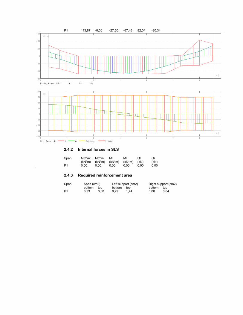
P1 113,87 -0,00 -27,50 -67,46 82,04 -80,34
0 1 2 3 4 5 61 5 0
1 0 0
5 0
0
- 5 0
- 1 0 0
- 1 5 0
[ m ]
[ k N * m ]
B e n d i n g M o m e n t U L S : M M r M c
0 1 2 3 4 5 6- 2 0 0
- 1 5 0
- 1 0 0
- 5 0
0
5 0
1 0 0
1 5 0
2 0 0
[ m ]
[ k N ]
S h e a r F o r c e U L S : V V r V c ( s t i r r u p s ) V c ( t o t a l )
2.4.2 Internal forces in SLS
Span Mtmax. Mtmin. Ml Mr Ql Qr(kN*m) (kN*m) (kN*m) (kN*m) (kN) (kN)
P1 0,00 0,00 0,00 0,00 0,00 0,00
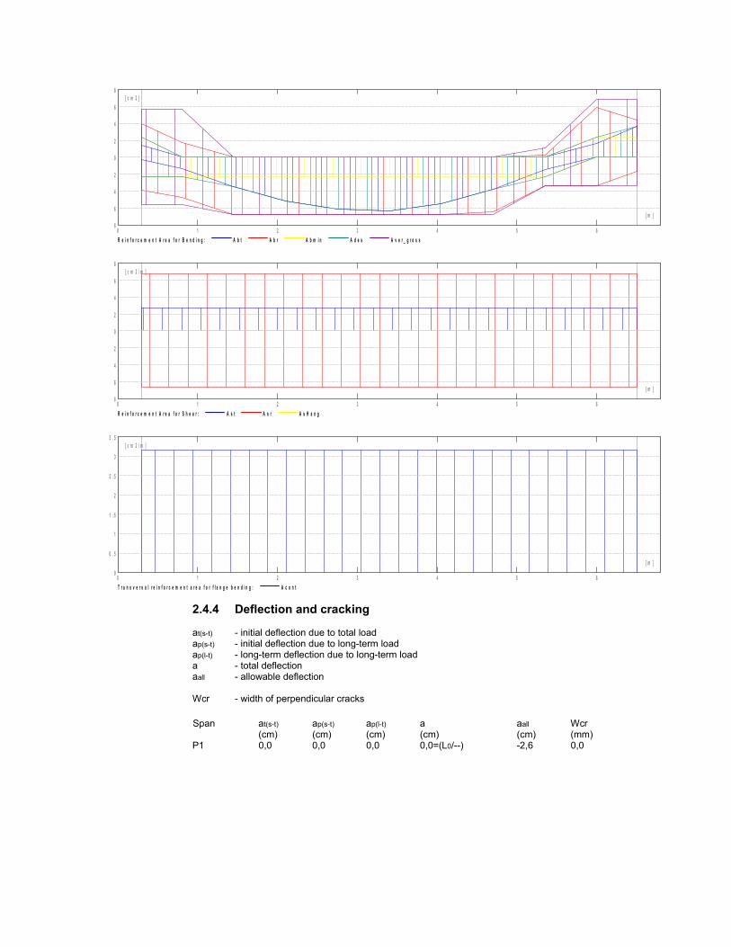
2.4.3 Required reinforcement area
Span Span (cm2) Left support (cm2) Right support (cm2)bottom top bottom top bottom top
P1 6,33 0,00 0,29 1,44 0,00 3,64
0 1 2 3 4 5 68
6
4
2
0
2
4
6
8
[ m ]
[ c m 2 ]
R e i n f o r c e m e n t A r e a f o r B e n d i n g : A b t A b r A b m i n A d e s A v e r _ g r o s s
0 1 2 3 4 5 68
6
4
2
0
2
4
6
8
[ m ]
[ c m 2 / m ]
R e i n f o r c e m e n t A r e a f o r S h e a r : A s t A s r A s H a n g
0 1 2 3 4 5 60
0 . 5
1
1 . 5
2
2 . 5
3
3 . 5
[ m ]
[ c m 2 / m ]
T r a n s v e r s a l r e i n f o r c e m e n t a r e a f o r f l a n g e b e n d i n g : A c o n t
2.4.4 Deflection and cracking
at(s-t) - initial deflection due to total loadap(s-t) - initial deflection due to long-term loadap(l-t) - long-term deflection due to long-term loada - total deflectionaall - allowable deflection
Wcr - width of perpendicular cracks
Span at(s-t) ap(s-t) ap(l-t) a aall Wcr(cm) (cm) (cm) (cm) (cm) (mm)
P1 0,0 0,0 0,0 0,0=(L0/--) -2,6 0,0

0 1 2 3 4 5 63
2
1
0
- 1
- 2
- 3
[ m ]
[ c m ]
D e f l e c t i o n s : a p ( s - t ) a p ( l - t ) a t ( s - t ) a a a d m
0 1 2 3 4 5 60 . 3
0 . 2
0 . 1
0
0 . 1
0 . 2
0 . 3
[ m ]
[ m m ]
C r a c k i n g : C w C w a d m
2.5 Theoretical results - detailed results:
2.5.1 P1 : Span from 0,30 to 6,50 (m)ULS SLS
Abscissa M max. M min. M max. M min. A bottom A top(m) (kN*m) (kN*m) (kN*m) (kN*m) (cm2) (cm2)0,30 5,65 -27,50 0,00 0,00 0,29 1,440,80 24,46 -0,00 0,00 0,00 1,29 0,001,45 64,21 -0,00 0,00 0,00 3,45 0,002,10 94,21 -0,00 0,00 0,00 5,16 0,002,75 111,35 -0,00 0,00 0,00 6,18 0,003,40 113,87 -0,00 0,00 0,00 6,33 0,004,05 99,00 -0,00 0,00 0,00 5,44 0,004,70 69,78 -0,00 0,00 0,00 3,77 0,005,35 28,10 -0,00 0,00 0,00 1,48 0,006,00 0,00 -30,67 0,00 0,00 0,00 1,626,50 0,00 -67,46 0,00 0,00 0,00 3,64
ULS SLSAbscissa Q max. Q max. Wcr(m) (kN) (kN) (mm)0,30 82,04 0,00 0,00,80 78,44 0,00 0,01,45 65,65 0,00 0,02,10 34,86 0,00 0,02,75 16,42 0,00 0,03,40 -18,67 0,00 0,04,05 -35,50 0,00 0,04,70 -53,33 0,00 0,05,35 -80,38 0,00 0,06,00 -87,11 0,00 0,06,50 -80,34 0,00 0,0
2.6 Reinforcement:
2.6.1 P1 : Span from 0,30 to 6,50 (m)Longitudinal reinforcement:
bottom 3 B500B 12 l = 6,74 from 0,03 to 6,773 B500B 12 l = 4,40 from 0,80 to 5,201 B500B 12 l = 2,34 from 0,04 to 0,04
assembling (top) 3 B500B 10 l = 5,46 from 0,35 to 5,80
support (B500B)3 B500B 12 l = 0,82 from 0,03 to 0,853 B500B 12 l = 1,42 from 5,35 to 6,771 B500B 12 l = 1,47 from 5,25 to 6,721 B500B 12 l = 2,34 from 0,04 to 0,041 B500B 12 l = 2,34 from 6,76 to 6,76
Surface reinforcement:2 B500B 12l = 6,44 from 0,18 to 6,62
Transversal reinforcement:
main stirrups 42 B500B 8 l = 1,27
e = 1*0,10 + 20*0,30 (m)2 B500B 12l = 6,44e = 1*-0,12 (m)
pins 42 B500B 8l = 1,27e = 1*0,10 + 20*0,30 (m)2 B500B 12l = 6,44e = 1*-0,12 (m)
3 Material survey:
Concrete volume = 1,02 (m3)
Formwork = 8,96 (m2)
Steel B500B
Total weight = 85,83 (kG)
Density = 84,15 (kG/m3)
Average diameter = 10,1 (mm)
Survey according to diameters:
Diameter Length Weight(m) (kG)
8 53,47 21,1110 16,37 10,0912 61,51 54,63
Steel B500B
Total weight = 2,84 (kG)
Density = 2,79 (kG/m3)
Average diameter = 8,0 (mm)
Survey according to diameters:
Diameter Length Weight(m) (kG)

8 7,21 2,84