FXV Leak Detectors
17
Manual No: 042-106-1 ● Revision: J Installation Instructions FXV Leak Detectors
Transcript of FXV Leak Detectors
Manual No: 042-106-1 ● Revision: J
Installation Instructions
FXV Leak Detectors
Notice
Veeder-Root makes no warranty of any kind with regard to this publication, including, but not limited to, the implied warranties ofmerchantability and fitness for a particular purpose.
Veeder-Root shall not be liable for errors contained herein or for incidental or consequential damages in connection with thefurnishing, performance, or use of this publication.
Veeder-Root reserves the right to change system options or features, or the information contained in this publication.
This publication contains proprietary information which is protected by copyright. All rights reserved. No part of this publicationmay be photocopied, reproduced, or translated to another language without the prior written consent of Veeder-Root.
Contact Red Jacket Technical Support for additional troubleshooting information at 800-323-1799.
DAMAGE GOODS/LOST EQUIPMENT
Thoroughly examine all components and units as soon as they are received. If any cartons are damaged or missing, write acomplete and detailed description of the damage or shortage on the face of the freight bill. The carrier's agent must verify theinspection and sign the description. Refuse only the damaged product, not the entire shipment.
VR must be notified of any damages and/or shortages within 30 days of receipt of the shipment, as stated in our Terms andConditions.
VEEDER-ROOT’S PREFERRED CARRIER
1. Fax Bill of Lading to V/R Customer Service at 800-234-5350.
2. Call V/R Customer Service at 800-873-3313 with the specific part numbers and quantities that were received damaged orlost.
3. VR will file the claim with the carrier and replace the damaged/missing product at no charge to the customer. CustomerService will work with production facility to have the replacement product shipped as soon as possible.
CUSTOMER’S PREFERRED CARRIER
1. Customer files claim with carrier.
2. Customer may submit a replacement purchase order. Customer Service will work with production facility to have thereplacement product shipped as soon as possible.
3. If “lost” equipment is delivered at a later date and is not needed, VR will allow a Return to Stock without a restocking fee.
4. VR will NOT be responsible for any compensation when a customer chooses their own carrier.
RETURN SHIPPING
For the parts return procedure, please follow the instructions in the “General Returned Goods Policy” pages of the “Policies andLiterature” section of the Veeder-Root North American Red Jacket Mechanical Products Price Book. Veeder-Root will not acceptany return product without a Return Goods Authorization (RGA) number clearly printed on the outside of the package.
©Veeder-Root 2017. All rights reserved.
Table of Contents
iii
FXV Leak Detectors - Installation InstructionsSafety Precautions ............................................................................................................1Warnings and Instructions ................................................................................................2
IMPORTANT SAFETY INFORMATION ...................................................................2PRELIMINARY PRECAUTIONS ..............................................................................2REQUIREMENTS FOR USE....................................................................................3OPERATING PRECAUTIONS .................................................................................3
Applications ......................................................................................................................4Static Head Pressure on Mechanical Leak Detector ................................................4
Installation ProcedureFor FX1V Models (Copper Vent Tube Installation)...................................................7For FX1V And FX1DV Models Stainless Steel [SST] Flexible Vent Hose Installation - Optional.................................................................7For FX2V Models (Copper Vent Tube Installation)...................................................8
TestingFX Leak Detector 3-Step Test ........................................................................................10
The Trip or Relaxed Position (Closed) ...................................................................11Leak Sensing Position (Metering)...........................................................................11Non-Leak Position (Open) ......................................................................................11
Third Party CertificationStatement of Third Party Certification .............................................................................12City of New York Certificate of Approval #4942 ..............................................................12
FiguresFigure 1. Static head ..............................................................................................4Figure 2. FXV Installation ports in The Red Jacket ................................................6Figure 3. Installing FXV in The Red Jacket pump ..................................................7Figure 4. Installing FX2V in The Red Jacket pump ................................................8Figure 5. Installing FXV in the Standard pump ....................................................10Figure 6. Leak detector operating positions .........................................................11
TablesTable 1. Red Jacket Equipment Certifications ......................................................12
1
FXV Leak Detectors - Installation Instructions
FX1V Part No. 116-056-5, FX2V Part No. 116-057-5
FX1DV Part No. 116-058-5, FX2DV Part No. 116-059-5
Safety Precautions
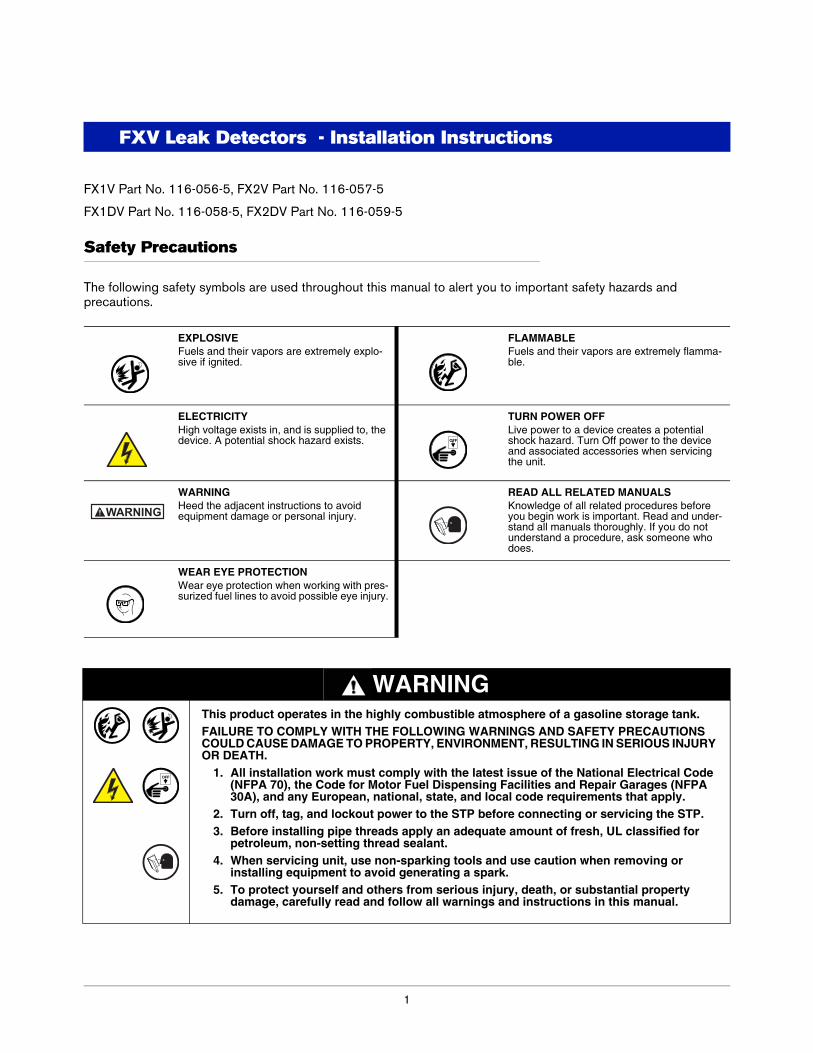
The following safety symbols are used throughout this manual to alert you to important safety hazards and precautions.
EXPLOSIVEFuels and their vapors are extremely explo-sive if ignited.
FLAMMABLEFuels and their vapors are extremely flamma-ble.
ELECTRICITYHigh voltage exists in, and is supplied to, the device. A potential shock hazard exists.
TURN POWER OFFLive power to a device creates a potential shock hazard. Turn Off power to the device and associated accessories when servicing the unit.
WARNINGHeed the adjacent instructions to avoid equipment damage or personal injury.
READ ALL RELATED MANUALSKnowledge of all related procedures before you begin work is important. Read and under-stand all manuals thoroughly. If you do not understand a procedure, ask someone who does.
WEAR EYE PROTECTIONWear eye protection when working with pres-surized fuel lines to avoid possible eye injury.
WARNINGThis product operates in the highly combustible atmosphere of a gasoline storage tank.FAILURE TO COMPLY WITH THE FOLLOWING WARNINGS AND SAFETY PRECAUTIONS COULD CAUSE DAMAGE TO PROPERTY, ENVIRONMENT, RESULTING IN SERIOUS INJURY OR DEATH.
1. All installation work must comply with the latest issue of the National Electrical Code (NFPA 70), the Code for Motor Fuel Dispensing Facilities and Repair Garages (NFPA 30A), and any European, national, state, and local code requirements that apply.
2. Turn off, tag, and lockout power to the STP before connecting or servicing the STP.3. Before installing pipe threads apply an adequate amount of fresh, UL classified for
petroleum, non-setting thread sealant. 4. When servicing unit, use non-sparking tools and use caution when removing or
installing equipment to avoid generating a spark.5. To protect yourself and others from serious injury, death, or substantial property
damage, carefully read and follow all warnings and instructions in this manual.
OFF
WARNING
OFF
FXV Leak Detectors - Installation Instructions Warnings and Instructions
2
Warnings and Instructions
IMPORTANT SAFETY INFORMATION
This section introduces the hazards and safety precautions associated with installing, inspecting, maintaining or servicing this product. Before performing any task on this product, read this safety information and the applicable sections in this manual, where additional hazards and safety precautions for your task will be found. Fire, explosion, electrical shock or pressure release could occur and cause death or serious injury, if these safe service procedures are not followed.
PRELIMINARY PRECAUTIONS
You are working in a potentially dangerous environment of flammable fuels, vapors, and high voltage or pressures. Only trained or authorized individuals knowledgeable in the related procedures should install, inspect, maintain or service this equipment.
Read the Manual
Read, understand and follow this manual and any other labels or related materials supplied with this equipment. If you do not understand a procedure, call 1-800-323-1799 to locate a qualified technician. It is imperative to your safety and the safety of others to understand the procedures before beginning work. Make sure your employees and any service contractors read and follow the instructions.
Follow the Regulations
Applicable information is available in National Fire Protection Association (NFPA) 30A; Code for Motor Field Dispensing Facilities and Repair Garages, NFPA 70; National Electrical Code (NEC), Occupational Safety and Hazard Association (OSHA) regulations and federal, state, and local codes. All these regulations must be followed. Failure to install, inspect, maintain or service this equipment in accordance with these codes, regulations and standards may lead to legal citations with penalties or affect the safe use and operation of the equipment.
Prevent Explosions and Fires
Fuels and their vapors will explode or burn, if ignited. Spilled or leaking fuels cause vapors. Even filling customer tanks will cause potentially dangerous vapors in the vicinity of the dispenser or island.
Working Alone
It is highly recommended that someone who is capable of rendering first aid be present during servicing. Familiarize yourself with Cardiopulmonary Resuscitation (CPR) methods, if you work with or around high voltages. This information is available from the American Red Cross. Always advise the station personnel about where you will be working, and caution them not to activate power while you are working on the equipment. Use the OSHA Lockout/Tagout procedures. If you are not familiar with this requirement, refer to OSHA documentation.
Working With Electricity Safely
Ensure that you use safe and established practices in working with electrical devices. Poorly wired devices may cause a fire, explosion or electrical shock. Ensure that grounding connections are properly made. Ensure that you do not pinch wires when replacing covers. Follow OSHA Lockout/Tagout requirements. Station employees and service contractors need to understand and comply with this program completely to ensure safety while the equipment is down. Before you start work, know the location of the Emergency Power Cutoff Switch (the E-STOP). This switch cuts off power to all fueling equipment and submerged turbine pumps and is to be used in the event of an emergency. The buttons on the console at the cashier’s station WILL NOT shut off electrical power to the pump/dispenser. This means that even if you press a button on the console labeled EMERGENCY STOP, ALL STOP, PUMP STOP, or something similar, fuel may continue to flow uncontrolled.
Hazardous Materials
Some materials may present a health hazard if not handled correctly. Ensure that you clean hands after handling equipment. Do not place any equipment in the mouth.
WARNING! FAILURE TO COMPLY WITH THE FOLLOWING WARNINGS AND SAFETY PRECAUTIONS COULD RESULT IN PROPERTY DAMAGE, INJURY OR DEATH.
FXV Leak Detectors - Installation Instructions Warnings and Instructions
3
FIRE HAZARD! Do NOT use power tools (Class I Division I and Class I Division II) during the installation or maintenance of equipment. Sparking could ignite fuel or vapors, resulting in fire.
CHEMICAL EXPOSURE HAZARD! Wear appropriate safety equipment during installation or maintenance of equipment. Avoid exposure to fuel and vapors. Prolonged exposure to fuel may cause severe skin irritations and possible burns.
REQUIREMENTS FOR USE
• The Red Jacket is designed for use only at facilities dispensing motor fuels.
• Application of The Red Jacket must be consistent with NFPA Code 30A, OSHA regulations, and federal, state and local fire codes, and other applicable local regulations.
• The selection of any Veeder-Root product must be based upon physical specifications and limitations and the product’s compatibility with the materials to be handled. Veeder-Root makes no warranty of fitness for a particular purpose.
• All Veeder-Root products should be used in accordance with applicable federal, state and local laws, ordinances and regulations.
• In addition to the specified torque values noted in this manual, when properly tightened, all flanged fittings should have metal-to-metal contact.
OPERATING PRECAUTIONS
• NO SMOKING. Extinguish all open flames and pilot lights, such as on RV appliances.
• TURN OFF cell phones and other electronic devices to avoid distractions while fueling.
• GASOLINE CAN BE HARMFUL OR FATAL IF SWALLOWED. Long-term exposure may cause cancer. Keep eyes and skin away from liquid gasoline and gasoline vapors. Avoid prolonged breathing of gasoline vapors.
WARNING! Before installing leak detector, review the application section in leak detector manual #5191 for limitations or restrictions on usage.
NOTICE! This instruction sheet should be kept with the end user of the leak detector for reference.
When using 117-182 Big-Flo Diaphragm Valve, refer to installation instructions #042-108-1 included with the valve. When using an FXV model leak detector with adapter housing #038-072-5, refer to installation instructions #041-415-1 included with the housing. FXV Leak Detectors are for use with all UL-listed 4-inch Red Jacket models containing a “P” or “AG” prefix; FE Petro UL-listed 4-inch “STP” models; Tokheim UL-listed 4-inch models — 585A-34 and 585A-150.
WARNING! Tampering with the screws or seals on this leak detector may inhibit operation and will void warranty.
DO NOT wire submersible pumps to run continuously. Red Jacket line leak detectors will not perform leak tests on pumping systems that run continuously.
NOTICE! ALL AIR MUST BE OUT OF THE SYSTEM FOR THE LEAK DETECTOR TO WORK PROPERLY. Before installing leak detector in the pump, fill the system with product by running the pump and delivering product from each dispenser (starting with the farthest from the pump and working to the pump) until all air is removed from system.
Certain regulatory bodies require that leak detectors remain in the system after the lines have been installed. The lines may be purged of air by back-pressuring the lines with an inert gas, such as helium or nitrogen, to a pressure of 25 psi (172 kPa). This may be done at the impact valve under the dispenser. When this pressure has been reached, the leak detector will be in the open position, By turning on the pump and gradually bleeding the gas from the line through a valve at the impact valve of the farthest dispenser, the line may be purged of air.
FXV Leak Detectors - Installation Instructions Applications
4
Applications
Static Head Pressure on Mechanical Leak Detector
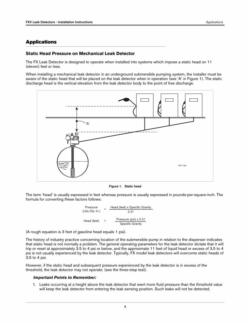
The FX Leak Detector is designed to operate when installed into systems which impose a static head on 11 (eleven) feet or less.
When installing a mechanical leak detector in an underground submersible pumping system, the installer must be aware of the static head that will be placed on the leak detector when in operation (see ‘A’ in Figure 1). The static discharge head is the vertical elevation from the leak detector body to the point of free discharge.
Figure 1. Static head
The term ‘head’ is usually expressed in feet whereas pressure is usually expressed in pounds-per-square-inch. The formula for converting these factors follows:
(A rough equation is 3 feet of gasoline head equals 1 psi).
The history of industry practice concerning location of the submersible pump in relation to the dispenser indicates that static head is not normally a problem. The general operating parameters for the leak detector dictate that it will trip or reset at approximately 3.5 to 4 psi or below, and the approximate 11 feet of liquid head or excess of 3.5 to 4 psi is not usually experienced by the leak detector. Typically, FX model leak detectors will overcome static heads of 3.5 to 4 psi.
However, if the static head and subsequent pressure experienced by the leak detector is in excess of the threshold, the leak detector may not operate. (see the three-step test).
Important Points to Remember:
1. Leaks occurring at a height above the leak detector that exert more fluid pressure than the threshold value will keep the leak detector from entering the leak sensing position. Such leaks will not be detected.
‘A’
106-7.eps
Pressure(Lbs./Sq. In.)
Head (feet) x Specific Gravity2.31
Pressure (psi) x 2.31Specific Gravity
Head (feet)
=
=
FXV Leak Detectors - Installation Instructions Applications
5
2. The threshold value for the reset pressure is a result of varying mechanical characteristics in the leak detector and may vary. Our experience shows that it is possible to encounter leak detectors that will work in a given situation when others won’t because they have a slightly higher threshold.
The effect of excessive static pressure can be observed when a simulated leak is placed into the line above the threshold height and then closed before the pump is turned on. Under normal operations, the leak detector will hesitate at the metering pressure for several seconds before opening up to full pump pressure. With excessive static head present, the pressure will increase immediately to full pump pressure. If under these conditions a leak is present, the pump is turned on and full pump pressure is realized immediately, the leak detector is not operating properly.
The amount of pressure experienced by the leak detector can be determined by installing a pressure gauge on the line test port of the pump. The gauge must remain at the level of the line test port and should have a low pressure range (i.e., 0 to 30 psi) to get accurate readings.
After the pump is turned off, use the valve on the test apparatus to bleed the pressure from the highest vertical point in the system, typically located at the dispenser shear valve. The gauge on the line test port will read the static head present on the leak detector.
Possible solutions to the problem of excessive static head are:
1. Test the operation of leak detectors. Replace the leak detector with a low threshold attempting to find one with a higher threshold by observing test results.
2. Modify the system by raising the leak detector to decrease its static head. This can be done by installing a longer riser pipe between the pump and the tank. Note that this will raise the pump inlet further from the bottom of the tank by the distance added to the riser.
3. Modify the piping system to include a pressure relieving check valve. The pressure relieving check valve will isolate the excessive static head pressure in the line from the FX Leak Detector. The leak detector will now only experience the static head from its level to that of the check valve. This allows the leak detector to return to the leak sensing position when the pressure has fallen in the system.
WARNING! The leak detecting capability of the system is functional only as long as the check valve does not leak. If the check valve leaks, the full static head is again transferred to the leak detector potentially rendering it inoperable. The leak detector functionality test must be performed with the check valve in line to assure functionality.
In all cases, operation of the mechanical leak detector must be verified by inducing a leak and confirming correct operation of the unit after it is installed at the site.
6
Installation Procedure
Always disconnect, lock out, and tag the power at the panel before starting to service the pump. Relieve pressure before installing or removing petroleum equipment.
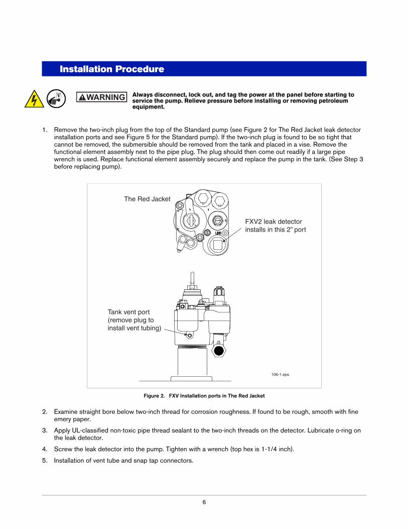
1. Remove the two-inch plug from the top of the Standard pump (see Figure 2 for The Red Jacket leak detector installation ports and see Figure 5 for the Standard pump). If the two-inch plug is found to be so tight that cannot be removed, the submersible should be removed from the tank and placed in a vise. Remove the functional element assembly next to the pipe plug. The plug should then come out readily if a large pipe wrench is used. Replace functional element assembly securely and replace the pump in the tank. (See Step 3 before replacing pump).
Figure 2. FXV Installation ports in The Red Jacket
2. Examine straight bore below two-inch thread for corrosion roughness. If found to be rough, smooth with fine emery paper.
3. Apply UL-classified non-toxic pipe thread sealant to the two-inch threads on the detector. Lubricate o-ring on the leak detector.
4. Screw the leak detector into the pump. Tighten with a wrench (top hex is 1-1/4 inch).
5. Installation of vent tube and snap tap connectors.
OFF WARNING
The Red Jacket
FXV2 leak detectorinstalls in this 2” port
Tank vent port(remove plug toinstall vent tubing)
106-1.eps

Installation Procedure Applications
7
For FX1V Models (Copper Vent Tube Installation)
a. Remove ¼-inch pipe plug from tank test port (on 6-inch Big-Flo applications, remove the ¼-inch pipe plug from the riser/flange assembly, for The Red Jacket pumps, see Figure 2 and for the Standard pump see Figure 5).
b. Apply a UL-classified non-toxic pipe thread sealant to the threads of the ¼-inch NPT straight vent tube fitting and install in tank test port. On 6-inch Big-Flo applications, the ¼-inch NPT straight vent tube fitting may be installed into the riser/flange assembly.
c. Apply a UL-classified non-toxic pipe thread sealant to the threads of the ¼-inch NPT 90-degree vent tube fitting and install in the leak detector vent opening in the cap of the leak detector.
d. Install the vent tubing into both fittings and tighten per instructions on package.
Figure 3. Installing FXV in The Red Jacket pump
For FX1V And FX1DV Models (STAINLESS STEEL [SST] Flexible Vent Hose Installation - Optional)
Requires kit 410874-001 containing hose assembly and stainless steel fittings. This kit needs to be ordered for new installation or replacement of copper tubing to flexible Stainless Steel hose.
a. Remove ¼ inch pipe plug from tank test port, see Figure 2 for The Red Jacket pump and Figure 5 for the Standard pump.
b. Apply a UL –classified non-toxic pipe thread sealant to the threads of the ¼-inch NPT Straight 37 Deg flare SST fitting and install in tank test port.
c. Apply a UL –classified non-toxic pipe thread sealant to the threads of the ¼-inch NPT 90 Deg elbow, 37 Deg flare SST fitting and install in the leak detector vent opening in the cap of the leak detector.
d. Install the SST flexible vent hose into the both fittings per instructions below.
• Make sure the tube flare and threads are clean.• Align the tube flare to the nose of fitting. The 90 deg. elbow on the tube end should connect to the
straight fitting and the straight tube end should connect to the 90 deg. elbow fitting.• Hand tighten the nut/sleeve (approx. 30 in-lb.).• Make alignment marks on the nut and fitting.• From marked position, tighten the nut further by 2 flats.• Make a 2nd set of alignment marks.
FXV leak detector installs in 2” port
1/4” NPT tubingfitting installs intank vent port
Top ViewSide View
Installation Procedure Applications
8
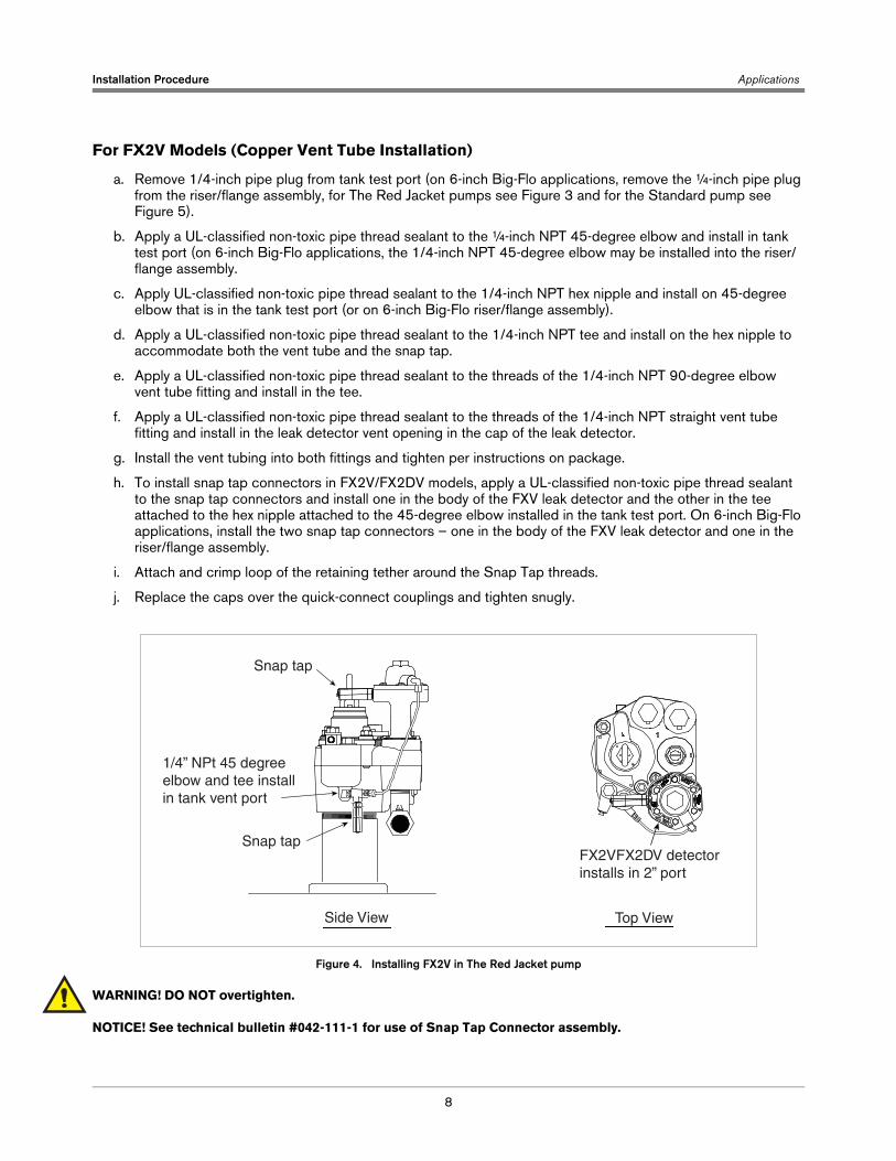
For FX2V Models (Copper Vent Tube Installation)
a. Remove 1/4-inch pipe plug from tank test port (on 6-inch Big-Flo applications, remove the ¼-inch pipe plug from the riser/flange assembly, for The Red Jacket pumps see Figure 3 and for the Standard pump see Figure 5).
b. Apply a UL-classified non-toxic pipe thread sealant to the ¼-inch NPT 45-degree elbow and install in tank test port (on 6-inch Big-Flo applications, the 1/4-inch NPT 45-degree elbow may be installed into the riser/flange assembly.
c. Apply UL-classified non-toxic pipe thread sealant to the 1/4-inch NPT hex nipple and install on 45-degree elbow that is in the tank test port (or on 6-inch Big-Flo riser/flange assembly).
d. Apply a UL-classified non-toxic pipe thread sealant to the 1/4-inch NPT tee and install on the hex nipple to accommodate both the vent tube and the snap tap.
e. Apply a UL-classified non-toxic pipe thread sealant to the threads of the 1/4-inch NPT 90-degree elbow vent tube fitting and install in the tee.
f. Apply a UL-classified non-toxic pipe thread sealant to the threads of the 1/4-inch NPT straight vent tube fitting and install in the leak detector vent opening in the cap of the leak detector.
g. Install the vent tubing into both fittings and tighten per instructions on package.
h. To install snap tap connectors in FX2V/FX2DV models, apply a UL-classified non-toxic pipe thread sealant to the snap tap connectors and install one in the body of the FXV leak detector and the other in the tee attached to the hex nipple attached to the 45-degree elbow installed in the tank test port. On 6-inch Big-Flo applications, install the two snap tap connectors – one in the body of the FXV leak detector and one in the riser/flange assembly.
i. Attach and crimp loop of the retaining tether around the Snap Tap threads.
j. Replace the caps over the quick-connect couplings and tighten snugly.
Figure 4. Installing FX2V in The Red Jacket pump
WARNING! DO NOT overtighten.
NOTICE! See technical bulletin #042-111-1 for use of Snap Tap Connector assembly.
1/4” NPt 45 degreeelbow and tee installin tank vent port
FX2VFX2DV detector installs in 2” port
Side View Top View
Snap tap
Snap tap
Installation Procedure Applications
9
6. Connect power to pump at the load center.
7. Clear remaining air from system as follows:
a. Turn on dispenser that is farthest from the leak detector but do not open nozzle. Wait 4 or 5 minutes or more. Look for leaks on parts worked on.
b. Shut off the pump and allow it to stand four or five minutes. Then start the pump again and open the nozzle farthest from the leak detector.
c. Continue to dispense enough gasoline, about 20 to 30 gallons (76 to 114 liters), to pump ALL air from the system.
NOTICE! If flow is restricted to about 3 gpm (11 lpm) or less with the nozzle open, the leak detector has not opened. Repeat Step 8a with increased running time of pump to insure the purging of all air. All air must be purged from the system or the leak detector will restrict flow to about 3 gpm.
8. Affix the enclosed decals to the dispenser dial glass on grade of gasoline upon which the leak detector is being installed. Additional decals are available; call customer service at 1-800-873-3313 and request P/N 046-200-1.
9. Inspect all threaded joints to assure they are tight and not leaking.
NOTICE! Snap tap connectors shall not be left permanently installed into impact/shear valves and must be removed upon completion of testing.
Special Installation Instructions
To minimize the chance of experiencing any disruption in the dispensing operation and maximize the benefits of this Red Jacket leak detector, please read this section.
It is very important that all of the dispenser solenoid valves in the system in which this leak detector will operate remain closed for approximately four seconds every time the submersible pump is activated. The leak detector can only perform a line test during this four-second window.
This test requires approximately two to four seconds, depending upon conditions present in the system. The dispenser solenoid valve must stay closed until the test is completed. This may be accomplished by utilizing delays integral to electronic dispensing equipment or by installing a retrofit delay in the junction box.
Past experience has shown that without this delay the leak detector has insufficient time to complete its line test and provide uninterrupted service.
Contact Red Jacket technical service at 1-800-323-1799 with any questions concerning this procedure.
10
Testing
U.S. Environmental Protection Agency (EPA) regulations require annual verification of operation of leak detector. To assure maintenance of leak detection capability. Red Jacket requires that operation of the mechanical leak detector be verified by testing upon start-up and that testing of the leak detector be performed routinely, at least annually.
NOTICE! Test procedure options for mechanical leak detectors are explained in Red Jacket Engineering Reports, RJ20 and RJ21. The Red Jacket Snap Tap Connectors allow the FX2V/FX2DV leak detector to be tested with the FXV Snap Tap Tester as an option to the above test methods. See Red Jacket literature #042-111-1 for test instructions using Snap Tap Connectors.
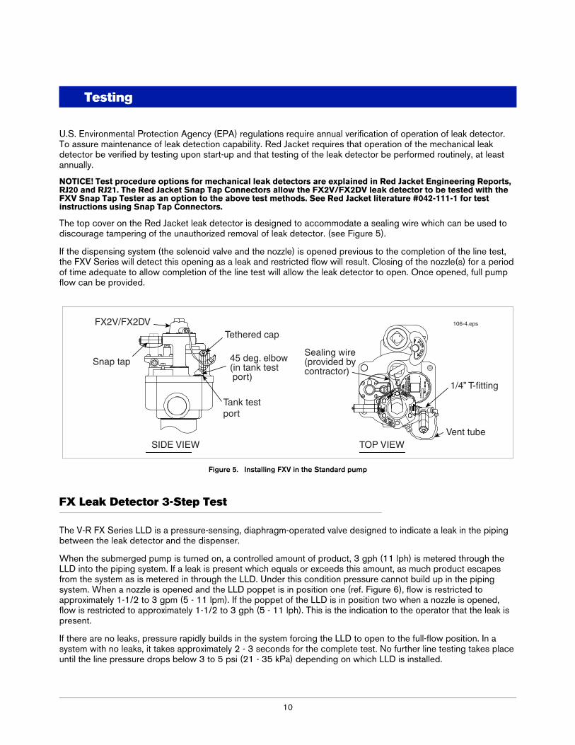
The top cover on the Red Jacket leak detector is designed to accommodate a sealing wire which can be used to discourage tampering of the unauthorized removal of leak detector. (see Figure 5).
If the dispensing system (the solenoid valve and the nozzle) is opened previous to the completion of the line test, the FXV Series will detect this opening as a leak and restricted flow will result. Closing of the nozzle(s) for a period of time adequate to allow completion of the line test will allow the leak detector to open. Once opened, full pump flow can be provided.
Figure 5. Installing FXV in the Standard pump
FX Leak Detector 3-Step Test
The V-R FX Series LLD is a pressure-sensing, diaphragm-operated valve designed to indicate a leak in the piping between the leak detector and the dispenser.
When the submerged pump is turned on, a controlled amount of product, 3 gph (11 lph) is metered through the LLD into the piping system. If a leak is present which equals or exceeds this amount, as much product escapes from the system as is metered in through the LLD. Under this condition pressure cannot build up in the piping system. When a nozzle is opened and the LLD poppet is in position one (ref. Figure 6), flow is restricted to approximately 1-1/2 to 3 gpm (5 - 11 lpm). If the poppet of the LLD is in position two when a nozzle is opened, flow is restricted to approximately 1-1/2 to 3 gph (5 - 11 lph). This is the indication to the operator that the leak is present.
If there are no leaks, pressure rapidly builds in the system forcing the LLD to open to the full-flow position. In a system with no leaks, it takes approximately 2 - 3 seconds for the complete test. No further line testing takes place until the line pressure drops below 3 to 5 psi (21 - 35 kPa) depending on which LLD is installed.
FX2V/FX2DVTethered cap
1/4” T-fitting
Vent tubeSIDE VIEW TOP VIEW
Sealing wire(provided bycontractor)
45 deg. elbow(in tank test port)
Tank testport
Snap tap
106-4.eps
Testing FX Leak Detector 3-Step Test
11
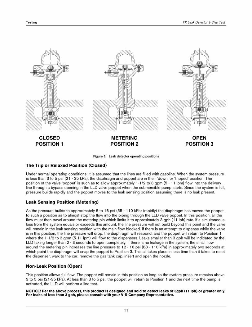
Figure 6. Leak detector operating positions
The Trip or Relaxed Position (Closed)
Under normal operating conditions, it is assumed that the lines are filled with gasoline. When the system pressure is less than 3 to 5 psi (21 - 35 kPa), the diaphragm and poppet are in their ‘down’ or ‘tripped’ position. The position of the valve ‘poppet’ is such as to allow approximately 1-1/2 to 3 gpm (5 - 11 lpm) flow into the delivery line through a bypass opening in the LLD valve poppet when the submersible pump starts. Since the system is full, pressure builds rapidly and the poppet moves to the leak sensing position assuming there is no leak present.
Leak Sensing Position (Metering)
As the pressure builds to approximately 8 to 16 psi (55 - 110 kPa) (rapidly) the diaphragm has moved the poppet to such a position as to almost stop the flow into the piping through the LLD valve poppet. In this position, all the flow must then travel around the metering pin which limits it to approximately 3 gph (11 lph) rate. If a simultaneous loss from the system equals or exceeds this amount, the line pressure will not build beyond this point and the valve will remain in the leak sensing position with the main flow blocked. If there is an attempt to dispense while the valve is in this position, the line pressure will drop, the diaphragm will respond, and the poppet will return to Position 1 where the 1-1/2 to 3 gpm (5-11 lpm) will flow to the dispensers. Leaks smaller than 3 gph will be indicated by the LLD taking longer than 2 - 3 seconds to open completely. If there is no leakage in the system, the small flow around the metering pin increases the line pressure to 12 - 16 psi (83 - 110 kPa) in approximately two seconds at which point the diaphragm will snap the poppet to Position 3. This all takes place in less time than it takes to reset the dispenser, walk to the car, remove the gas tank cap, insert and open the nozzle.
Non-Leak Position (Open)
This position allows full flow. The poppet will remain in this position as long as the system pressure remains above 3 to 5 psi (21-35 kPa). At less than 3 to 5 psi, the poppet will return to Position 1 and the next time the pump is activated, the LLD will perform a line test.
NOTICE! Per the above process, this product is designed and sold to detect leaks of 3gph (11 lph) or greater only. For leaks of less than 3 gph, please consult with your V-R Company Representative.
CLOSEDPOSITION 1
OPENPOSITION 3
METERINGPOSITION 2
12
Third Party Certification
Statement of Third Party Certification
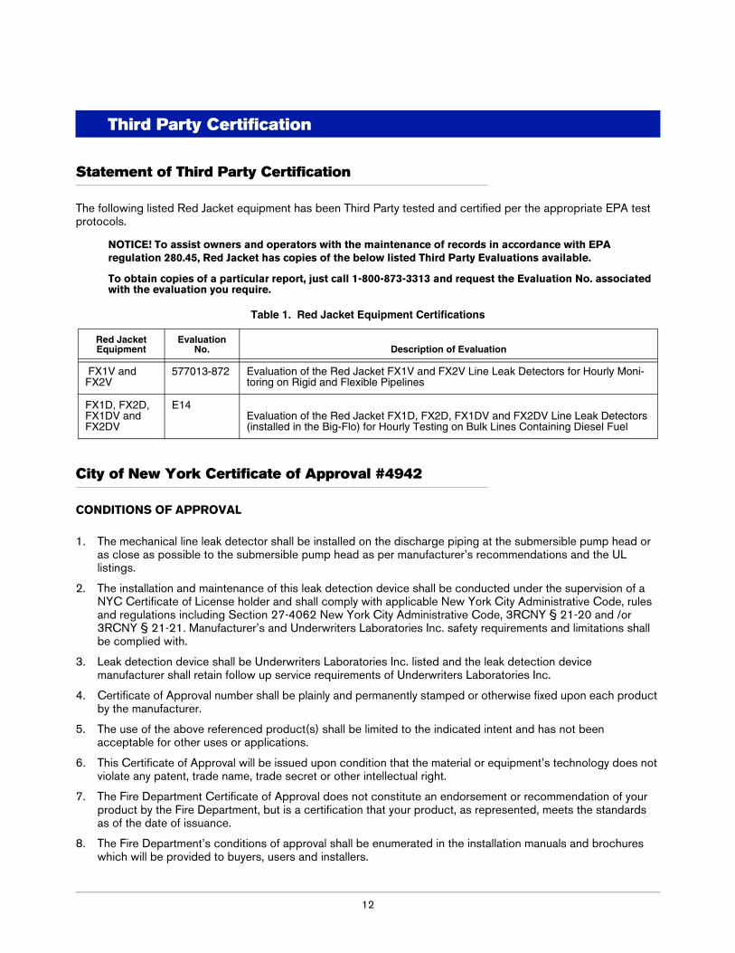
The following listed Red Jacket equipment has been Third Party tested and certified per the appropriate EPA test protocols.
NOTICE! To assist owners and operators with the maintenance of records in accordance with EPA regulation 280.45, Red Jacket has copies of the below listed Third Party Evaluations available.
To obtain copies of a particular report, just call 1-800-873-3313 and request the Evaluation No. associated with the evaluation you require.
City of New York Certificate of Approval #4942
CONDITIONS OF APPROVAL
1. The mechanical line leak detector shall be installed on the discharge piping at the submersible pump head or as close as possible to the submersible pump head as per manufacturer’s recommendations and the UL listings.
2. The installation and maintenance of this leak detection device shall be conducted under the supervision of a NYC Certificate of License holder and shall comply with applicable New York City Administrative Code, rules and regulations including Section 27-4062 New York City Administrative Code, 3RCNY § 21-20 and /or 3RCNY § 21-21. Manufacturer’s and Underwriters Laboratories Inc. safety requirements and limitations shall be complied with.
3. Leak detection device shall be Underwriters Laboratories Inc. listed and the leak detection device manufacturer shall retain follow up service requirements of Underwriters Laboratories Inc.
4. Certificate of Approval number shall be plainly and permanently stamped or otherwise fixed upon each product by the manufacturer.
5. The use of the above referenced product(s) shall be limited to the indicated intent and has not been acceptable for other uses or applications.
6. This Certificate of Approval will be issued upon condition that the material or equipment’s technology does not violate any patent, trade name, trade secret or other intellectual right.
7. The Fire Department Certificate of Approval does not constitute an endorsement or recommendation of your product by the Fire Department, but is a certification that your product, as represented, meets the standards as of the date of issuance.
8. The Fire Department’s conditions of approval shall be enumerated in the installation manuals and brochures which will be provided to buyers, users and installers.
Table 1. Red Jacket Equipment Certifications
Red Jacket Equipment
Evaluation No. Description of Evaluation
FX1V and FX2V
577013-872 Evaluation of the Red Jacket FX1V and FX2V Line Leak Detectors for Hourly Moni-toring on Rigid and Flexible Pipelines
FX1D, FX2D, FX1DV and FX2DV
E14Evaluation of the Red Jacket FX1D, FX2D, FX1DV and FX2DV Line Leak Detectors (installed in the Big-Flo) for Hourly Testing on Bulk Lines Containing Diesel Fuel
Third Party Certification City of New York Certificate of Approval #4942
13
9. The Fire Department reserves the right to withdraw this approval at any time in the event there is a reasonable doubt that the product does not operate or perform as required by code, the conditions of this resolution or as represented in your application.
10. As the manufacturer of this equipment/material, you should be aware that any end users who fail to comply with the condition as outlined in this certificate will be subject to enforcement action which may include fines and imprisonment.

For technical support, sales orother assistance, please visit:
www.veeder.com