FW100 Dust Concentration Monitor - SICK
120
OPERATING INSTRUCTIONS Description Installation Operation Title FW100 Dust Concentration Monitor
Transcript of FW100 Dust Concentration Monitor - SICK

O P E R A T I N G I N S T R U C T I O N S
DescriptionInstallationOperation
Title
FW100Dust Concentration Monitor

Document Information
Described ProductProduct name: FW100
Document IDTitle: Operating Instructions FW100Part No.: 8008905Version: 1.1Release: 2012-12
ManufacturerSICK AGErwin-Sick-Str. 1 · 79183 Waldkirch · GermanyPhone: +49 7641 469-0Fax: +49 7641 469-1149E-mail: [email protected]
Place of ManufactureSICK Engineering GmbHBergener Ring 27 · 01458 Ottendorf-Okrilla · Germany
TrademarksIBM is a trademark of the International Business Machine Corporation. MS-DOS is a trademark of the Microsoft Corporation.Windows is a trademark of the Microsoft Corporation.Other product names used in this document may also be trade-marks and are only used for identification purposes.
Original DocumentsThe English edition 8008905 of this document is an original docu-ment of SICK AG.SICK AG assumes no liability for the correctness of an unauthor-ized translation.Please contact the manufacturer or your local representative in case of doubt.
Legal informationSubject to change without notice.
© SICK AG. All rights reserved.
2 8008905 · © SICK AG
Subj
ect t
o ch
ange
with
out n
otice

Operating Instructions FW100
Dust Concentration Monitor
Subj
ect t
o ch
ange
with
out n
otice
Contents
Notes on this Document ....................................................................................................7
1 Safety Instructions...............................................................................................................8
1.1 Intended Use .............................................................................................................................8
1.2 Authorized Personnel..............................................................................................................8
1.3 Safety Information and Protection Measures.................................................................81.3.1 Danger from Electrical Equipment ................................................................................................. 9
1.3.2 Danger due to Hot, Corrosive, or Pressurized Gases ............................................................ 9
1.3.3 Danger due to Laser Beam............................................................................................................... 9
1.3.4 Purge-Air Failure .................................................................................................................................... 9
1.3.5 Detecting and Preventing Malfunctions .................................................................................... 10
1.3.6 Shutdown, Removal from Service, and Storing System Components........................... 10
2 Product Description.......................................................................................................... 11
2.1 Features and Applications ................................................................................................. 13
2.2 Operating Principle and Measured Variables .............................................................. 142.2.1 Operating Principle ............................................................................................................................ 14
2.2.2 Response time ................................................................................................................................... 15
2.2.3 Check Cycle.......................................................................................................................................... 15
2.3 Device Components............................................................................................................. 182.3.1 Transmitter/Receiver Unit .............................................................................................................. 18
2.3.2 Assembly Elements for Transmitter/Receiver Units ............................................................. 21
2.3.3 Connection Unit ................................................................................................................................. 22
2.3.4 External Purge-Air Unit (Optional) ................................................................................................ 24
2.3.5 Adapter fpr Instrument Air Supply................................................................................................ 24
2.3.6 Data Acquisition, Communication, Measured Value Output, and Display Options.... 25
2.3.7 ASC Option............................................................................................................................................ 26
2.3.8 Elbow Plug............................................................................................................................................. 26
2.3.9 Check Filter Set for FW100............................................................................................................ 26
2.4 Device Configuration ........................................................................................................... 27
2.5 Technical Data ...................................................................................................................... 28
8008905 · © SICK AG 3

FW100 Operating Instructions
Dust Concentration Monitor
Subj
ect t
o ch
ange
with
out n
otice
2.6 Dimensions and Order Numbers....................................................................................... 302.6.1 Transmitter/Receiver Unit .............................................................................................................. 30
2.6.2 Flange with Pipe .................................................................................................................................. 31
2.6.3 Tri-Clamp• Flange ............................................................................................................................. 31
2.6.4 Connection Unit................................................................................................................................... 32
2.6.5 External Purge-Air Unit (Optional) ................................................................................................ 33
2.6.6 Weatherproof Cover for Transmitter/Receiver Unit .............................................................. 34
3 Assembly and Installation...............................................................................................35
3.1 Project Planning .................................................................................................................... 37
3.2 Assembly ................................................................................................................................. 283.2.1 Installing the Assembly Elements for the Transmitter/Receiver Units ........................... 38
3.2.2 Installing the Connection Unit ....................................................................................................... 40
3.2.3 Installing the Optional External Purge-Air Unit ........................................................................ 41
3.2.4 Fitting the Weatherproof Covers .................................................................................................. 42
3.3 Installation............................................................................................................................... 433.3.1 General Instructions and Prerequisites .................................................................................... 43
3.3.2 Connection Unit .................................................................................................................................. 43
3.3.3 Connecting/Commissioning the Optional External Purge-Air Unit ................................... 45
3.3.4 Installing the Purge-Air Supply ....................................................................................................... 46
3.3.5 Connecting optional Devices ........................................................................................................ 48
4 Commissioning and Parameterization ........................................................................51
4.1 Basics ....................................................................................................................................... 534.1.1 General Notes .................................................................................................................................... 53
4.1.2 Prerequisites ....................................................................................................................................... 53
4.2 Installing and Connecting the Transmitter/Receiver Unit....................................... 544.2.1 Aligning the Transmitter/Receiver Unit ....................................................................................... 54
4.2.2 Starting up the Transmitter/Receiver Unit ................................................................................ 55
4.3 Connecting the Device........................................................................................................ 56
4.4 Parameterization ................................................................................................................... 574.4.1 Customer-Specific Parameterization........................................................................................... 57
4.4.2 Calibration for Dust Concentration Measurement................................................................. 59
4.4.3 Filter Bag Control ................................................................................................................................ 60
4.4.4 Data backup ........................................................................................................................................ 62
4.4.5 Starting Standard Measuring Mode ............................................................................................ 63
4.5 Parameterizing Optional Devices ................................................................................... 644.5.1 Data Memory / Event Memory ..................................................................................................... 64
4.5.2 CAN Module ......................................................................................................................................... 67
4.5.3 Second Analog Output ..................................................................................................................... 68
4.5.4 LCD .......................................................................................................................................................... 68
4.5.5 ASC Option............................................................................................................................................ 69
4 8008905 · © SICK AG

Operating Instructions FW100
Dust Concentration Monitor
Subj
ect t
o ch
ange
with
out n
otice
5 Maintenance....................................................................................................................... 71
5.1 General ..................................................................................................................................... 73
5.2 Maintaining the Transmitter/Receiver Unit.................................................................. 745.2.1 Cleaning the Transmitter/Receiver Unit (Externally) ............................................................. 74
5.2.2 Cleaning the Optical Boundary Surfaces................................................................................... 74
5.3 Maintaining the Purge-Air Supply .................................................................................... 765.3.1 Connection Unit with Integrated Purge-Air Supply ................................................................. 77
5.3.2 External Purge-Air Unit (Optional) ................................................................................................. 78
5.4 Removal from Service.......................................................................................................... 79
6 Troubleshooting................................................................................................................. 81
6.1 Malfunctions........................................................................................................................... 83
6.2 Warnings and Malfunction Messages .......................................................................... 846.2.1 Warnings ................................................................................................................................................ 84
6.2.2 Malfunction Messages ..................................................................................................................... 85
6.2.3 Other Malfunctions and Abnormal Behavior ............................................................................ 87
6.3 Removal of Malfunctions.................................................................................................... 886.3.1 Adjusting the Laser Beam............................................................................................................... 88
6.3.2 Checking the Laser Beam for free Transit (FW101) ............................................................ 89
6.3.3 Checking the FW101 Receiver Optics for Correct Movement ......................................... 90
6.4 Test and Diagnosis Options............................................................................................... 916.4.1 Testing the Signal Output ................................................................................................................ 91
6.4.2 Check Cycle.......................................................................................................................................... 91
6.4.3 Linearity Check.................................................................................................................................... 92
7 Repairs.................................................................................................................................. 93
7.1 Transmitter/Receiver Unit.................................................................................................. 967.1.1 Replacing the Cover and/or Protection tube (FW101)........................................................ 96
7.1.2 Replacing the Sintered Metall Flter (FW101) .......................................................................... 96
7.1.3 Replacing the Entire T/R Unit Connector................................................................................... 96
7.1.4 Checking/Replacing the Battery for the Transmitter/Receiver Unit ................................ 98
7.2 Connection Unit..................................................................................................................... 997.2.1 Connection Unit without Purge-Air Supply................................................................................. 99
7.2.2 Connection Unit with Integrated Purge-Air Supply ...............................................................101
7.2.3 Replacing the LCD Module ...........................................................................................................103
8008905 · © SICK AG 5

FW100 Operating Instructions
Dust Concentration Monitor
Subj
ect t
o ch
ange
with
out n
otice
8 Parts Overview.................................................................................................................105
8.1 Standard Components.......................................................................................................1078.1.1 Transmitter/Receiver Units .......................................................................................................... 108
8.1.2 Assembly Elements ........................................................................................................................ 108
8.1.3 Connection Units.............................................................................................................................. 109
8.1.4 External Purge-Air Units (Optional) ........................................................................................... 109
8.1.5 Miscellaneous................................................................................................................................... 109
8.2 Options ...................................................................................................................................1108.2.1 Transmitter/Receiver Units .......................................................................................................... 110
8.2.2 Connection Units.............................................................................................................................. 110
8.2.3 Weatherproof Covers ................................................................................................................... 111
8.2.4 Accessories for Testing the Device.......................................................................................... 111
8.2.5 Miscellaneous .................................................................................................................................. 111
8.3 Consumable Parts for 2-Year Operation......................................................................1118.3.1 Transmitter/Receiver Units .......................................................................................................... 111
8.3.2 Connection Unit with Internal Purge-Air Supply.................................................................... 111
8.3.2 External Purge-Air Unit (Optional) .............................................................................................. 111
8.4 Spare Parts............................................................................................................................1128.4.1 Transmitter/Receiver Unit ............................................................................................................ 112
8.4.2 Connection Unit................................................................................................................................ 112
8.4.3 Miscellaneous .................................................................................................................................. 112
9 Appendix............................................................................................................................ 113
9.1 Standard Settings for the FW100..................................................................................1159.1.1 FW101................................................................................................................................................. 115
9.1.2 FW102................................................................................................................................................. 116
9.2 Password ...............................................................................................................................117
6 8008905 · © SICK AG

Operating Instructions FW100
Dust Concentration Monitor
Notes On This DocumentSu
bjec
t to
chan
ge w
ithou
t not
ice
Notes On This Document
These operating instructions describe the functioning of the FW100 opto electronic dust
concentartion monitor in both variations FW101 and FW102. They serve for understanding
the device function and contain general information on planning, assembly, installation,
commissioning, maintenance, and troubleshooting. The description of the available device
components is intended to help you during the planning phase to determine the optimum
configuration for the particular application.
These operating instructions only cover standard applications that conform to the technical
data listed. Your SICK representative will be glad to provide you with additional information
and support for special applications. We strongly advise that you contact a SICK specialist
for consultation on special applications.
Note • Always read these operating instructions carefully before commencing work. The safety
instructions and warnings must be followed at all times.
• Some system components (such as the side-channel compressor of the purge-air units)
are supplied with separate user information. This information must also be read carefully.
Symbols used in this document
For quick access and reasons of clarity, important safety information is specially highlighted
in these operating instructions. They are provided at the relevant points in the chapters.
Note Provides information on the features of the device or system, along with additional tips.
ATTENTION
Important
Indicates a risk of damage to the device or system components and potential functional
impairments.
DANGER
Warning
Identifies potential danger for personnel, particularly due to electrical equipment or as a
result of incorrect handling of the device or system components. These warnings are
intended to protect you from (fatal) injuries.
Always read warnings carefully and follow them at all times!
8008905 · © SICK AG 7

FW100 Operating Instructions
Dust Concentration Monitor
Safety Instructions
Subj
ect t
o ch
ange
with
out n
otice
1 Safety Instructions
1.1 Intended Use
The FW100 measuring system is used for measuring the dust concentration in exhaust
gases and waste air ducts. It must only be operated in the manner intended by the
manufacturer and in accordance with the following information. In particular, it is important
that:
• The system is operated in accordance with the technical data and specifications
regarding assembly, connection, ambient, and operating conditions (see the
documentation supplied, the order documents, device documents, and rating plates)
• All of the measures required to maintain the device, for example, for maintenance and
inspection requirements, are provided.
1.2 Authorized Personnel
Those responsible for personal safety must ensure that:
• All work on the measuring system is carried out by qualified personnel and checked by
the experts responsible. These persons must be qualified by virtue of their expertise (training, education,
experience) or understanding of the relevant standards, specifications, accident
prevention regulations, and properties of the system. It is crucial that these persons be
able to identify and avoid potential hazards in good time. Technical experts are those persons defined in DIN VDE 0105, IEC 364, or other directly
equivalent standards.
• These persons must be familiar with the hazards posed during operation, such as those
caused by hot, toxic, or pressurized gases, gas/liquid mixtures, or other media, and must
have received special training on how to operate the measuring system.
1.3 General Safety Information and Protection Measures
Handling or using the device incorrectly can result in personal injury or material damage.
Read this chapter carefully and ensure that you observe the safety precautions for the
FW100 at all times. Always observe the warnings provided in these operating instructions.
The following applies at all times:
• The relevant legal stipulations and associated technical regulations must be observed
when preparing and carrying out work on the installation.
• All work must be carried out in accordance with the local, system-specific conditions and
with due consideration paid to the operating dangers and specifications.
• The operating instructions for the measuring system and plant documentation must be
available on site. The instructions for preventing danger and damage contained in these
documents must be observed at all times.
• Suitable safety equipment and personal protection measures must be available in
accordance with the potential hazard and must be used by the personnel.
8 8008905 · © SICK AG

Operating Instructions FW100
Dust Concentration Monitor
Safety InstructionsSu
bjec
t to
chan
ge w
ithou
t not
ice
1.3.1 Danger from Electrical Equipment
The FW100 measuring system is an item of electrical equipment designed for use in
industrial power installations. When working on power connections or on live components,
make sure that the power supply is switched off. If necessary, replace shock protection
measures before reconnecting the power supply.
1.3.2 Danger Due to Hot, Corrosive, or Pressurized Gases
The transmitter/receiver unit is mounted directly on the gas-carrying duct. In installations
with a low hazard potential (no risk of injury, ambient pressure, low temperatures, no risk of
explosion), this unit can be installed and removed while the installation is in operation,
provided that the applicable specifications and safety regulations for the installation are
adhered to and all necessary and suitable protective measures are taken.
DANGER
Warning
Installations with toxic gases, high temperatures, high pressure, or risk of explosion must be
shutdown before these components are installed or removed!
1.3.3 Danger Due to Laser Beam
WARNING
The FW100 uses a laser with laser class 2. To prevent blinding:
‡ Never look directly into the laser beam.
‡ Do not direct the FW100 laser beam towards people.
‡ Take into account reflections of the laser beam.
1.3.4 Purge-Air Failure
The purge-air supply protects the transmitter/receiver unit fitted in the duct against hot or
corrosive gases. It must remain switched on when the plant is shut down. A purge-air supply
failure can quickly destroy the transmitter/receiver unit. For this reason, the operator must
ensure that:
ATTENTION
‡ The purge-air supply operates reliably and without interruption.
‡ A failure is detected immediately (for example, by using pressure monitors).
‡ The transmitter/receiver unit is removed from the duct in the event of a purge-air failure
and the duct openings are covered (for example, with a flange cover).
8008905 · © SICK AG 9

FW100 Operating Instructions
Dust Concentration Monitor
Safety Instructions
Subj
ect t
o ch
ange
with
out n
otice
1.3.5 Detecting and Preventing Malfunctions
Any deviations from normal operation must be regarded as a serious indication of a
functional impairment. These include:
‡ Significant drifts in the measurement results
‡ A rise in power consumption
‡ A rise in system component temperature
‡ Actuating of monitoring devices
‡ Unusually strong vibrations / unusual operating noise from a purge-air fan
‡ Smoke or unusual odors.
1.3.6 Shutdown, Removal from Service, and Storing System Components
The FW100 measuring system must remain switched on when the plant is shut down. The
purge-air supply must never be switched off.
If the FW100 operating voltage is switched off for a prolonged period (more than 3 days),
all the device components must be disassembled and stored in a dry, dust-free location.
10 8008905 · © SICK AG

Features and Applications
Operating Principle
Device Components
Device Configuration
Technical Data
Dimensions and Part Numbers
FW100
Dust Concentration Monitor
Product Description


Operating Instructions FW100
Dust Concentration Monitor
Product DescriptionSu
bjec
t to
chan
ge w
ithou
t not
ice
2 Product Description
2.1 Features and Applications
The FW100 series from SICK is designed to conduct continuous measurements of very low
(0.1 mg/m3) to medium (200 mg/m3 and higher) dust concentrations in gases (temperature
above dew point). These measuring devices can be used in a wide range of application and
feature by low installation effort and simple handling.
System features and advantages
• High resolution and measuring speed
• Measuring of the dust content independent of height and fluctuations of the gas velocity
• No influence of moisture or charge of the particles
• Defined zero point
• Easy to install, no mechanical adjustment required
• No calibration to dust-free measuring path required
• Simple operation and configuration with user-friendly software
• Automatic check cycle
• Automatic compensation of contaminations (type FW101)
• Minimum maintenance requirements.
Application range
Applications ‡ In pure gas, downstream of electrostatic precipitators
– Continuous measurement and monitoring of dust concentrations
– Protection of flue gas desulfurization plants
‡ In pure gas, downstream of modern fabric filters
– Monitoring, detection, and identification of defective filters and bags
– Prevention of the release of expensive production materials and toxic contents in
continuous processes
‡ For monitoring and/or closed-loop control purposes in exhaust/intake air systems
Sectors • Power supply: Power stations, heating systems
• Waste disposal: Refuse incineration plants
• Process engineering: Grinding and metering plants
• Metal processing: Steel and aluminum processing
• Foodstuff industry: Filling bulk materials
• Brake linings and Eternit production
Compliance The measurement system is approved according to Federal German Pollution Control Act
(13th, 17th and 27th Implementing Ordinance) and German Clean Air Regulations, an-
nounced in GMBL 2000, no. 60, pg. 1192.
8008905 · © SICK AG 13

FW100 Operating Instructions
Dust Concentration Monitor
Product Description
Subj
ect t
o ch
ange
with
out n
otice
2.2 Operating Principle
2.2.1 Operating Principle
The FW100 operates according to the scattered light measurement principle (forward
scattering). Since it is extremely sensitive, this principle is particularly suitable for measuring
very small particle concentrations.
A laser diode directs a beam of modulated light in the visible range (wavelength approx.
650 nm) at the dust particles in the gas flow. The light scattered by the particles is recorded
by a highly sensitive detector which is positioned in an angle of approx. 15 ° to the beam
axis. The received signal is electrically amplified and supplied to the measuring channel of a
microprocessor as the central part of the measuring, control and evaluation electronics. The
point of intersection between the transmitted beam and the receiver aperture defines the
measuring volume in the gas duct.
The transmitting power of the laser diode is continuously controlled by measuring a part of
the transmitted intensity with a microchip in the laser diode. This received signal is also
amplified and supplied to the monitor channel of the microprocessor. In this way lowest
brightness changes of the transmitted laser beam can be detected and take into account
in the determination of the output signal.
Fig. 2.1: FW100 Operating principle
The measured scattered light intensity is proportional to the dust concentration. Since the
scattered light intensity doesn't only depend on the particle number (dust content) but also
on the visual qualities of the particles, the FW100 must be calibrated with a gravimetric
comparison measurement to secure an exact measuring of the dust concentration. The
calibration coefficients determined at this measurement are entered in FW100 (see
Section. 4.4.2) in the form:
cc2: square
cc1: linear
cc0: absolute
c = cc2 · SI² + cc1 · SI + cc0 c = Dust concentration
SI = Scattered light intensity
cc = calibration coefficiant
The manufacturer settings are cc2 = 0, cc1 = 1, cc0 = 0.
Transmitter/receiver unit
Laser diode
Gas duct
Detector
Measuring volume
14 8008905 · © SICK AG

Operating Instructions FW100
Dust Concentration Monitor
Product DescriptionSu
bjec
t to
chan
ge w
ithou
t not
ice
2.2.2 Response Time
The response time (t90) is the time taken by the FW100 to reach 90% of the end value after
a sudden change in the measured value (see Fig. 2.2). The t90 time can be set to any value
between 0.1 and 600 s. Setting a higher t90 time provides better attenuation of transient
fluctuations in the measured value and malfunctions to produce a "smoother" output signal.
Fig. 2.2: Response time
2.2.3 Check Cycle
The check cycle is used for automatically checking that the transmitter/receiver is
functioning properly. The check cycle can be triggered automatically at fixed intervals
(setting in MEPA-FW, see Section 4.4.1) and/or manually (1 min after the power supply has
been connected, or the system has been switched from "Maintenance" to "Measure" in
MEPA-FW).
The check values can be given out at the analog output (see Section 4.4.1).
Notes • When the check values are being determined, the value last measured is given out at the
analog output.
• If the check values are not given out at the analog output, the current measured value is
given out once the check value has been determined.
• The "Maintenance" relay is activated to signal that a check cycle is in process.
• With the LCD option, a check cycle is indicated with a plain-text "check cycle" display and
as a status output at relay 6.
• Automatic check cycles are carried out periodically from the parameterized time interval.
A re-start begins if the interval setting is changed or 1 min after:
– Change from „Maintenance“ to „Measure“ mode
– Reset (power off/on)
– Switch-on of the power voltage after power failure.
Measured
value
in %
Measured value with t90 response time
90 % of the peak
Process change
t90
t in s
100
98
96
94
92
90
88
86
8410 20 30 40 50 60 70 80 90 100
8008905 · © SICK AG 15

FW100 Operating Instructions
Dust Concentration Monitor
Product Description
1
Check cycle FW101
If a check cyle is carried out, inadmissible deviations appearing by the normal behavior are
signaled as a malfunction. If a malfunction is present, you can trigger a check cycle manually
to locate the cause of the problem (see Chapter 6).
The check cycle lasts approx. 310 s and comprises:
The values are only given
out to the analog output in
case of activation (see
Section 4.4.1).
• 40 s contamination measurement of the optical boundary surfaces, zero and check value
• 90 s output of the contamination value
• 90 s output of the check value
• 90 s output of the zero value.
Fig. 2.3: FW101 check cycle output on plotter
Contamination Measurement
In order to measure the contamination on the optical boundary surfaces, the FW101 moves
the receiver optics mechanically to a reference position. As a result, the optics measure the
light emitted by the laser diode directly. The intensity value measured during the movement
is compared with the factory settings to calculate a correction factor. In this way, the FW101
can fully compensate for any contamination levels.
If the contamination value is lower than 70 %, a analog value is given out during the check
cycle in a range between Live Zero and 20 mA and proportional to the contamination value
(device status „Operation“). For contamination values higher than 70 % always Live Zero is
given out (device status „Malfunction“).
Fig. 2.4: FW101 contamination and check value measurement
Check Value Measurement
(Span test)
Following to the contamination measurement, the check value is determined (receiver
optics is in reference position). Once a reference measurement has been carried out with a
light intensity of 100 %, the FW101 reduces the intensity of the laser diode to 70 % and
compares the value measured by the receiver with the expected value. If these two value
deviate more than ±2 %, the device generates an error signal. The error message is lifted
again if the next check cycle passes successfully.
Degree of
contamination
Check value (70 % value, span)Zero value (Live Zero)
End
check cycle
Start
Check cyclecontamination
output
Zero value
output
Paper feed
Check value
output
Receiver optics in reference position
Subj
ect t
o ch
ange
with
out n
otice
6 8008905 · © SICK AG

Operating Instructions FW100
Dust Concentration Monitor
Product DescriptionSu
bjec
t to
chan
ge w
ithou
t not
ice
Zero Value Measurement
In order to monitor the zero point, the FW101 deactivates the laser diode, and the reception
signal must also be zero. In this way, drifts or zero-point eviations in the entire system (e.g.
caused by an electronic defect) can be reliably detected. If the “zero-value” deviation is out-
side the specified range, an error signal is generated.
Check cycle FW102
At the FW102, the measuring linearity is checked during a check cycle. The check cycle lasts
approx. 200 s and comprises a:
• 20 s measurement of zero and check value
The values are only given
out to the analog output in
case of activation (see
Section 4.4.1).
• 90 s output of the check value
• 90 s output of the zero value.
Fig. 2.5: FW102 check cycle output on plotter
Check Value Measurement
(Span test)
The FW102 measures the check point with the receiver optics in the measuring position.
During this time, the light intensity changes between 70 and 100%. Thanks to a large
number of intensity shifts, which are evaluated statistically, the FW102 enables the check
point to be measured with pinpoint accuracy (prerequisite: dust contents > approx. 2 mg/
m³, otherwise the theoretically calculated 70 % value is given out.
The check value is evaluated in the same way as with the FW101 (error messages in case
of deviations of more than ±2 %).
Zero Value Measurement
The FW102 carries out a zero-point measurement in the same way with the FW101.
Start
Check cycle
Check value (70 % value, span)
Zero value
output
Output
check value
Zero value (Live Zero)
End
check cycle
Paper feed
8008905 · © SICK AG 17

FW100 Operating Instructions
Dust Concentration Monitor
Product Description
Subj
ect t
o ch
ange
with
out n
otice
2.3 Device Components
Device Variants
• FW101 for use in gas ducts with a diameter greater than 250 mm.
The device is mounted on the duct using a flange with tube.
• FW102 for use in gas ducts with a diameter greater than 150 mm.
The FW102 can be mounted on a flange with fitting (Tri-Clamp®) or a 1” sleeve on the
duct.
FW100 Components
Possible device configurations see section 2.4.
• Transmitter/receiver unit
• Flange with pipe / flange with fitting / 1” sleeve
• Connection unit
– with integrated purge-air supply (for internal duct pressure -70 ... +10 mbar)
– without purge-air supply. The following is, therefore, required:
• External purge-air supply (for internal duct pressure -70 ... +70 mbar)
Fig. 2.6 Overview of the FW100 components
Connection unit with
purge-air supply
Connection
unit without
purge-air
supply
External purge-air
unit option
Transmitter/receiver unit
Purge-air hose
Signal cable
MEPA-FW
operating and
configuration
program
Flange with pipe
RS 232
Power supply
Duct Optional
18 8008905 · © SICK AG

Operating Instructions FW100
Dust Concentration Monitor
Product DescriptionSu
bjec
t to
chan
ge w
ithou
t not
ice
2.3.1 Transmitter/Receiver Unit
The transmitter/receiver unit consists of two main modules:
• Electronic unit
It contains the optical and electronic modules for transmitting and receiving the light be-
am, as well as processing and evaluating signals.
• Measuring probe
The measuring probe is designed in different forms, nominal lengths and for different gas
temperature ranges and defined the device variant.
The transmitter/receiver unit is connected to the connection unit using a 16-pole cable with
a connector, and has a 24 V d.c. power supply. Clean purging air is supplied to a purge-air
nozzle to cool the probe and keep clean the optical boundary surfaces.
FWSE101 Transmitter/Receicer Unit
The transmitter/receiver units are available in the following versions:
Fig. 2.7: FWSE101 transmitter/receicer unit nominal length 435 / 735 mm
Nominal lengthNL in mm
max. Gas temperature
in °C
Protection tube Use for
Length L in mm Material
435220
300
Stainless steel
Hastelloy Corrosive gases
400 Stainless steel
735220
600
Stainless steel
Hastelloy Corrosive gases
400 Stainless steel
1035220
900Stainless steel Wall and isolation thick-
ness up to 720 mm400 Stainless steel
1335220
1200Stainless steel Wall and isolation thick-
ness up to 1020 mm400 Stainless steel
Electronic unit
Probe head
with receiver
optics
Purge-air nozzle
Purge-air outlets at high temperature
version (HT) up to 400 °C
Cleaning opening for transmitter optics
NL
Connector for signal cable
L
(Flange with pipe)
(Duct wall)
Protection tube
Measuring
opening
8008905 · © SICK AG 19

FW100 Operating Instructions
Dust Concentration Monitor
Product Description
Subj
ect t
o ch
ange
with
out n
otice
Fig. 2.8 FWSE101 transmitter/receicer unit nominal length 1035 / 1335 mm
Notes • Transmitter/receiver units with nominal length > 735 mm are exclusive scheduled for the
installation in thick-wall or double walled ducts with wall and isolation thickness of approx.
400 mm to 1020 mm.
• The distance between inside duct wall and measuring opening may be max. 450 mm
(see Fig. 2.8).
FWSE102 Transmitter/Receicer Unit
The following versions are available:
Fig. 2.9: FWSE102 1“ transmitter/receicer unit (NL 280 mm is shown)
Cleaning opening for transmitter optics
NL
(485 mm)
Laser with drive electronics in housing
(must be within the channel wall/isolation)
max. 450 mm
(Duct wall/isolation)
L
Nominal length NLin mm
Mounting type Duct diameter in mm
1801“ sleeve
> 150Flange with fitting (Tri-Clamp®)
2801“ sleeve
Flange with fitting (Tri-Clamp®)
Purge-air nozzle
Connector for signal cable
Cleaning opening for transmitter optics
NL
Electronic unit Measuring probe
Probe head with
receiver optics
1“ thread
20 8008905 · © SICK AG
Operating Instructions FW100
Dust Concentration Monitor
Product DescriptionSu
bjec
t to
chan
ge w
ithou
t not
ice
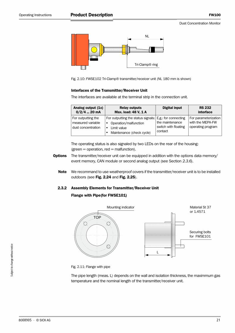
Fig. 2.10: FWSE102 Tri-Clamp® transmitter/receicer unit (NL 180 mm is shown)
Interfaces of the Transmitter/Receiver Unit
The interfaces are available at the terminal strip in the connection unit.
The operating status is also signaled by two LEDs on the rear of the housing:
(green = operation, red = malfunction).
Options The transmitter/receiver unit can be equipped in addition with the options data memory/
event memory, CAN module or second analog output (see Section 2.3.6).
Note We recommand to use weatherproof covers if the transmitter/receiver unit is to be installed
outdoors (see Fig. 2.24 and Fig. 2.25).
2.3.2 Assembly Elements for Transmitter/Receiver Unit
Flange with Pipe(for FWSE101)
Fig. 2.11: Flange with pipe
The pipe length (meas. L) depends on the wall and isolation thickness, the maximmum gas
temperature and the nominal length of the transmitter/receiver unit.
Analog output (1x) 0/2/4 ... 20 mA
Relay outputsMax. load: 48 V, 1 A
Digital input RS 232interface
For outputting the
measured variable
dust concentration
For outputting the status signals:
• Operation/malfunction
• Limit value
• Maintenance (check cycle)
E.g.: for connecting
the maintenance
switch with floating
contact
For parameterization
with the MEPA-FW
operating program
NL
Tri-Clamp® ring
TOP
L
Material St 37
or 1.4571
Securing bolts
for FWSE101
Mounting indicator
8008905 · © SICK AG 21

FW100 Operating Instructions
Dust Concentration Monitor
Product Description
2
Flange with Fitting / 1“ Sleeve (for FWSE102)
Fig. 2.12 Assembly elements for FWSE102
2.3.3 Connection Unit
The connection unit contains the power supply for the transmitter/receiver unit, terminals for
the network connection and input/output signals, and an RS 232 interface (9-pole Sub-D
socket) for connecting a PC/laptop. The connection cable for the transmitter/receiver unit
(16-pole, shielded) is securely attached to the connection unit. The cable length is 3 m or
10 m.
Two versions are available:
Connection Unit without Purge-air Supply
Fig. 2.13: Connection unit without purge-air supply
Connection Unit with Integrated Purge-air Supply
This version also has a purge-air fan, air filter, and purge-air nozzle for connecting the purge-
air hose for the transmitter/receiver unit.
Gas temperature
Nominal length of the FWSE101 transmitter/receiver unit (in mm)
435 735 1035 1335
< 150 °C 130
240
130
240
500 800 1100
Measure L
(in mm)> 150 °C 240 500
Seal Tri-Clamp• Fitting
flange
Flange with fitting (Tri-Clamp®) 1“ sleeve
Power supply unit
LCD option
Terminal block
Subj
ect t
o ch
ange
with
out n
otice
2 8008905 · © SICK AG

Operating Instructions FW100
Dust Concentration Monitor
Product DescriptionSu
bjec
t to
chan
ge w
ithou
t not
ice
Fig. 2.14: Connection unit with integrated purge-air supply
The connection units can also be fitted with the LCD module with additional relay outputs
(see section 2.3.6).
The different versions are also defined by a type key:
Connection unit: AK1-X-XXXX-X-X
Integrated purge-air supply
- P: With
- N: Without
Cable length
- 03: 3 m
- 10: 10 m
Supply voltage
- WR: Power supply 100 ... 240 V AC (wide-range power unit)
- 02: 24 V DC
LCD option
- N: No display
- D: Display
Special version
- 0: Without
- S: Special design (e.g. stainless steel housing)
Note At use of the connection unit with integrated purge-air supply, a purge-air hose with nominal
diameter 25 mm is required in addition to sypply the transmitter/receiver unit sends (see
Section 8.1.5). The length must be the same as the cable length.
Purge-air fan
Air filter
Power supply unit
(on rear of mounting plate)
LCD option
I/O board with
terminal block
Mounting plate
Purge-air nozzle
8008905 · © SICK AG 23

FW100 Operating Instructions
Dust Concentration Monitor
Product Description
Subj
ect t
o ch
ange
with
out n
otice
2.3.4 External Purge-Air Unit (Optional)
The connection unit with integrated purge-air supply cannot be used if the internal duct
pressure is greater than +10 mbar. In this case, the option with an external purge-air unit
must be used. It features a high-performance fan and is suitable for use in pressurized ducts
of up to 70 mbar.
Fig. 2.15: Pugre-air unit SLV 4 with purge-ait reduction
The purge-air hose nominal diameter 40 mm (length 5 m or 10 m, scope of supply ) is
connected to purge-air nozzle of the transmitter/receiver unit via the separate component
purge-air reduction (see Section 8.1.4).
A weatherproof cover is available if the system is to be used outdoors (see Fig. 2.23).
2.3.5 Adapter for Instrument Air Supply
The FW100 can be operated also with instrument air instead of the purge-air supplies from
the connection unit AK1-P or an external purge-air unit. To connect the instrument air, an
adapter is available with connection thread G 1/4“ and installed reduction nozzle (installing
at the purge-air nozzle of the transmitter/receiver unit).
Fig. 2.16: Adapter for instrument air supply
Puge-air
hose
Air filter
Fan (standard
type 2BH13)
BaseplateCover with opening
(part of the purge-air reduction)
(Purge-air nozzle)
Purg-air
reduction
Reduction
nozzle
Inner
diameter
Admission
pressure
D3 3 mm 1 ... 3 bar
D2 2 mm 3 ... 6 bar
Reduction nozzle
G 1/4“
(Ø 25)
Purge-air consumption
approx. 6 ... 13 m³/h
(depending on admission
pressure)
24 8008905 · © SICK AG

Operating Instructions FW100
Dust Concentration Monitor
Product DescriptionSu
bjec
t to
chan
ge w
ithou
t not
ice
2.3.6 Data Acquisition, Communication, Measured Value Output, and Display Options
Note The options described here can only be installed by the manufacturer.
Data Memory/Event Memory
Installed in transmitter/ receiver unit
This option enables up to 7,280 measured values and 100 events to be recorded in
continuous operation. The measured values can be saved as mean values over a definable
period (e.g. every half hour) and assigned a time stamp by an integrated real-time clock. All
changes in the device operating status (maintenance, limit value violation, error statuses)
are recorded as events The menu-driven MEPA-FW parameterization program reads or
displays the data (see section 4.5.1).
CAN Module
Installed in transmitter/ receiver unit
A separate evaluation unit is available to complement the existing input/output and
connection options (see section 8.2.5). To enable communication with this evaluation unit
via the CAN bus, the transmitter/receiver unit must be equipped with this module. In this
way, up to three FW100 systems can be connected to the evaluation unit with a data
transfer of up to 1000 m.
Second Analog Output
Installed in transmitter/ receiver unit
Instead of a CAN module, the transmitter/receiver unit can be fitted with a second,
electrically isolated analog output (0/2/4 ... 20 mA). It has the same technical specifications
as the standard output. The measuring range can be parameterized independently (see
section 4.5.3).
Note If a CAN module or second analog output is installed, you can only install two additional relay
outputs (operation/malfunction and limit value/maintenance; can be parameterized in
MEPA-FW). The following option is recommended here.
LCD
Installed in connection unit
To display the measured values and status information, a module with a 2-row LCD, two LED
for signaling "Maintenance" (green) and "Malfunction" (red), and three additional relays for
maintenance, the second limit value, and the check cycle can be integrated in the
connection unit. This module is activated by the transmitter/receiver unit, which must be
configured accordingly, that is, it must be ordered with the LCD.
The LCD shows the following status information:
Indications on the LCD Meaning
„Limit1 “ Limit 1 is exceeded
„ Limit2“ Limit 2 is exceeded
„Limit1 Limit2“ Limit 1 and limit 2 are exceeded
„Soft “ „Maintenance“ mode is set via MEPA-FW (Software maintenance)
„Hard (In1)“ „Maintenance“ mode is set by using of an external switch (hardware
maintenance; see section 3.3)
„Soft Hard (In1)“ Hardware and software maintenance are set
„Warning xxx“ see Section 6.2.1
„Malfunction xxx“ see Section 6.2.2
8008905 · © SICK AG 25

FW100 Operating Instructions
Dust Concentration Monitor
Product Description
Subj
ect t
o ch
ange
with
out n
otice
2.3.7 ASC Option (Automatic Self Control, only for FW102)
Using this option, the FW102 can be checked for proper device function. Especially at very
low dust concentrations near to zero an information is possible with it whether the device
still measures or has a malfunction (= Live Zero at the analog output).
The supervision is based on a permanent determination of the difference between the hig-
hest and lowest measuring value in an adjustable time interval. The device works normal if
a preselectable value was exceeded at least once (parameterization see Section 4.5.5).
Otherwise a malfunction message appears (“Automatic Self Control“). In this case it has to
be checked, whether there is really a device malfunction or merely minimal dust concentra-
tions are existing no longer measurable with the FW100.
2.3.8 Elbow Plug
To prevent damages at the signal cable to the connection unit by installation the FWSE101
in vertical ducts (cable connection from the side, see Fig. 4.1) and use of the weatherproof
cover for analyzer (see Fig. 2.24), we recommend to connect the transmitter/receiver unit
via the elbow plug option (see Section 8.2.1).
2.3.9 Check Filter Set for FW100
A linearity test can be performed to check the correct device function (see Section 6.4.3).
Absorption filters with defined transmission values are placed in the beam path and the
values are compared with those measured by the FW100. If the results match and are
within the permissible tolerance, the FW100 is functioning correctly. The absorption filters
and brackets are supplied with a case (see Section 8.2.4)
26 8008905 · © SICK AG

Operating Instructions FW100
Dust Concentration Monitor
Product DescriptionSu
bjec
t to
chan
ge w
ithou
t not
ice
2.4 Device Configuration
The components required for the measuring system depend on the application. The
following table will help you decide which components you need.
Transmitter/Receiver Unit
Note Choose the nominal length of the transmitter/receiver unit so that the measuring opening
has a sufficient distance of the duct inside wall (> 100 mm). The measuring opening (see
Fig. 2.7) must not be in the middle of the duct!
Power and Purge-Air Supply
*: Instrument air provided by the customer (free of dust, oil, humidity, condensates, non corrosive)
ATTENTION
Important
If the gas temperature is higher than 220 °C, the optional external purge-air unit must be
installed! Only FWSE101 transmitter/receicer units up to 400 °C can be used.
Flange with Pipe (only for FWSE101)
The pipe length is assigned tightly to the nominal length of the transmitter/receiver unit (see
Section 2.3.2).
Internal duct diameterr
in mm
Wall and isolation thickness
in mm
Exhaust gases, waste air Type of the transmitter/receiver unit
max. temperaturein °C
Composition
> 150
max. 10
220 Low corrosive
FWSE102 1“ NL180
FWSE102 Tri-Clamp® NL180
max. 100FWSE102 1“ NL280
FWSE102 Tri-Clamp® NL280
> 250 max. 150220
Low corrosive FWSE101 NL435, up to 220 °C
Strongly corrosive FWSE101 NL435 Hastelloy, up to 220 °C
400 FWSE101 NL435, up to 400 °C
> 300
max. 400220
Low corrosive FWSE101 NL735, up to 220 °C
Strongly corrosive FWSE101 NL735 Hastelloy, up to 220 °C
400 FWSE101 NL735, up to 400 °C
400 ... 720220
Low corrosive
FWSE101 NL1035, up to 220 °C
400 FWSE101 NL1035, up to 400 °C
700 ... 1020220 FWSE101 NL1335, up to 220 °C
400 FWSE101 NL1335, up to 400 °C
Internal duxt pressure mbar
Connection and supply components
Purge-air Power
-50 ... +10 AK1 -P-XXXX-X-X + purge-air hose DN 25
-50... +70Optional external purge-air supply
+ purge-air reduction AK1 -N-XXXX-X-X
-50 ... 1000 Adapter for instrument air supply *
8008905 · © SICK AG 27

FW100 Operating Instructions
Dust Concentration Monitor
Product Description
Subj
ect t
o ch
ange
with
out n
otice
2.5 Technical Data
Measured value acquisition
Measured variable Scattered light intensity
after gravimetric comparision measurement, dust concentration in mg/m³
Measuring range Minimum range: 0 ... 5 mg/m³ higher ranges avaliable on request
stepplessly variableMaximum range: 0 ... 200 mg/m³
Measuring accuracy ±2 % of upper range limit (full scale)
Response time 0.1 ... 600 s; freely selectable
Application data
Gas temperature (above
dewpoint)
FW101, FW102 standard version -20 °C ... 220 °C
FW101 high temperature version -20 °C ... 400 °C
Internal duct pressure Connection unit with purge-air supply -50 mbar ... +10 mbar
External purge-air unit (optional) -50 mbar ... +70 mbar
Instrument air (provided by the customer) -50 mbar ... 1 bar
Ambient temperature Transmitter/receiver unit -20 ... +50 °C
Connection unit with purge-air supply;
Purge air intake temperature
-20 ... +45 °C
Connections
Analog output Electrically isolated, 0/2/4 ... 20 mA, max. load 750 Ω; 10 bit, resolution ± 1 %
Relay outputs For status signals operation/malfunction, limit value, maintenance; Load carrying capacity: 48 V, 1 A;
floating; further relay with optional LCD
Interfaces RS 232 for laptop/PC (9600, 8, N, 1)
Digital input Dig in 1 = connection for maintenance switch with floating contact
Options
LCD 2-row display for the measured variables, as well as warning and malfunction messages
With additional relay outputs for maintenance, second limit value, check cycle
Second analog output Electrically isolated, 0/2/4 ... 20 mA, max. load 750 Ω; can be parameterized separately
CAN module For connecting the FW100 to an evaluation unit
Data memory/event memory For storing and displaying up to 7,280 measured values and 100 events
Power supply
Connection unit Power supply: 100...240 V AC, 47...63 Hz; opt. 24 V d.c. ± 2 V
Power consumption: max. 15 W without purge-air supply
approx. 70 W with purge-air supply
Transmitter/receiver unit Power supply: 24 V from connection unit
Power consumption: max. 4 W
External purge-air unit (optional) (with fan: 2BH13)
Power supply: 200 ... 240 V/345...415 V at 50 Hz;
220...275 V/380...480 V at 60 Hz
Rated current: 2,6 A/Y 1,5 A
Motor rating: 0.37 kW at 50 Hz; 0.45 kW at 60 Hz
Dimensions (W x H x D)
Transmitter/receiver unit FW101 NL 435 mm 150 mm x 150 mm x 645 mm
NL 735 mm 150 mm x 150 mm x 945 mm
NL 1035 mm 150 mm x 150 mm x 1245 mm
NL 1335 mm 150 mm x 150 mm x 1545 mm
FW102 150 mm x 150 mm x 440 mm
28 8008905 · © SICK AG

Operating Instructions FW100
Dust Concentration Monitor
Product DescriptionSu
bjec
t to
chan
ge w
ithou
t not
ice
Dimensions (W x H x D)
Connection unit without purge-air supply 200 mm x 200 mm x 130 mm
with purge-air supply 300 mm x 400 mm x 220 mm
External purge-air unit (optional) 550 mm x 550 mm x 258 mm; with weatherproof cover: 605 mm x 550 mm x 350 mm
Weight
Transmitter/receiver unit FW101 NL 435 mm 5.0 kg
NL 735 mm 6.3 kg
NL 1035 mm 8.0 kg
NL 1335 mm 9.5 kg
FW102 2.7 kg
Connection unit without purge-air supply 3.7 kg
with purge-air supply 13.5 kg
External purge-air unit (optional) 14 kg
Miscellaneous
Class of protection Transmitter/receiver unit, connection unit IP 65
External purge-air unit (optional) IP 54
Electrical safety According to EN 61010-1
• Connection unit and external purge-air unit (optional) protection class I
• Transmitter/receiver unit protection class III
Laser Laser class 2; Power < 1 mW; wavelength between 640 nm and 660 nm
Signal cable length 3 m, 10 m (LiYCY 8x2x0,25 mm²) other lengths available on request
Length of purge-air hose DN 25 3 m , 10 m other lengths available on request
Purge air flow rate Connection unit with internal purge-air supply ca. 5 ... 10 m³/h
External purge-air unit (optional) ca. 40 ... 60 m³/h
8008905 · © SICK AG 29

FW100 Operating Instructions
Dust Concentration Monitor
Product Description
Subj
ect t
o ch
ange
with
out n
otice
2.6 Dimensions and Part Numbers
All dimensions in mm
2.6.1 Transmitter/Receiver Unit
Fig. 2.17 FW101 transmitter/receiver unit
81 55
Ø 6
0
15
0
Ø 5
3
NL
NL
L
L1
128
L
(485) Ø 7
6
Ø 25
FWSE101 NL 435 / 735
FWSE101 NL 1035 / 1335
NL L
435 300
735 600
1035 900
1335 1200
FWSE102 1“
NL L1 L2
180 50 179
280 150 79
FWSE102 Tri-Clamp®
81
Ø 2
5
15
0
NL
L1
L2
Ø 25
Type Transmitter/receiver unit Part no.
FWSE101 NL435, up to 220 °C 7047500
FWSE101 NL735, up to 220 °C 7047501
FWSE101 NL435, up to 400 °C 7047502
FWSE101 NL735, up to 400 °C 7047503
FWSE101 Hastelloy NL435, up to 220 °C 7047570
FWSE101 Hastelloy NL735, up to 220 °C 7047571
FWSE101 NL1035, up to 220 °C 7047576
FWSE101 NL1335, up to 220 °C 7047577
FWSE101 NL1035, up to 400 °C 7047578
FWSE101 NL1335, up to 400 °C 7047579
FWSE102 Tri-Clamp® NL180 7047505
FWSE102 1“ NL180 7047506
FWSE102 Tri-Clamp® NL280 7047507
FWSE102 1“ NL280 7047508
L2 NL
30 8008905 · © SICK AG

Operating Instructions FW100
Dust Concentration Monitor
Product DescriptionSu
bjec
t to
chan
ge w
ithou
t not
ice
2.6.2 Flange with Pipe
Fig. 2.18 Flange with pipe
2.6.3 Tri-Clamp® Flange
Abb. 2.19 Tri-Clamp• flange and seal
TOP
D1
LD2
D3
Dim. Flange with pipe
D100 D150
D1 Ø 76 Ø 127
D2 Ø 100 Ø 150
D3 Ø 130 Ø 190
L 240, 500 800, 1100
G M10 M12
45° 45°
G
Typ Flange with pipe Part no.
D100
Length 130 mm, St37 2017845
Length 240 mm, St37 2017847
Length 500 mm, St37 2017849
Length 130 mm, V4A 2017846
Length 240 mm, V4A 2017848
Length 500 mm, V4A 2017850
D150
Length 800 mm, St37 7047580
Length 1100 mm, St37 7047581
44.5
Ø 3
8.1
Ø 3
4.8
Ø 4
3
Ø 5
0.5
Tri-Clamp®-FDA seal 1 1/2“ Tri-Clamp® flange
Part no. 7047770 Part no. 7047779
8008905 · © SICK AG 31
FW100 Operating Instructions
Dust Concentration Monitor
Product Description
Subj
ect t
o ch
ange
with
out n
otice
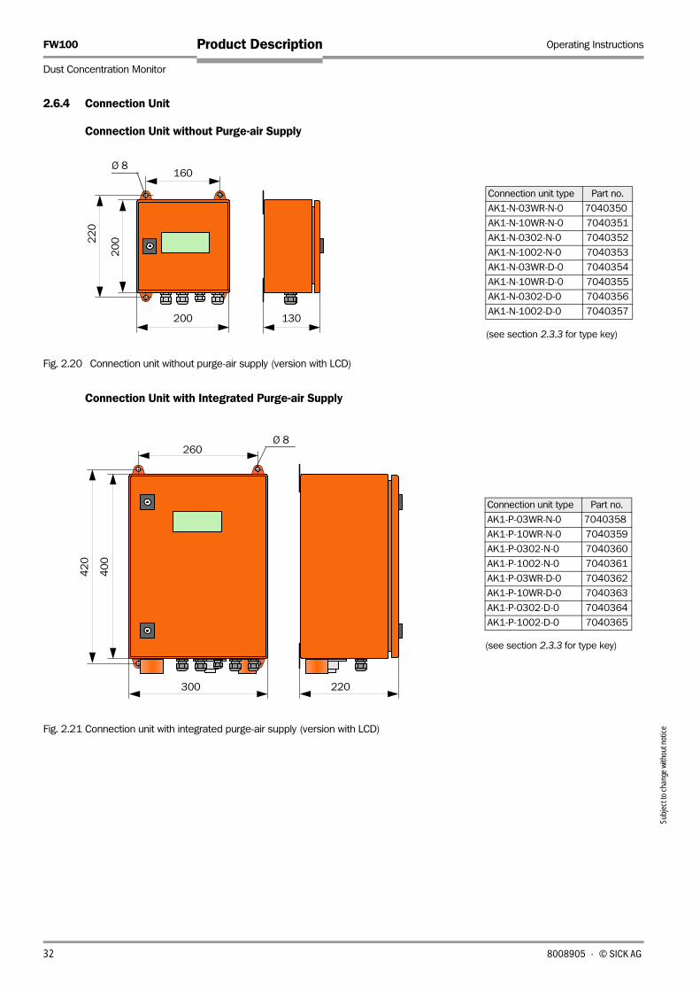
2.6.4 Connection Unit
Connection Unit without Purge-air Supply
Fig. 2.20 Connection unit without purge-air supply (version with LCD)
Connection Unit with Integrated Purge-air Supply
Fig. 2.21 Connection unit with integrated purge-air supply (version with LCD)
200 130
20
0
160
22
0
Ø 8
(see section 2.3.3 for type key)
Connection unit type Part no.
AK1-N-03WR-N-0 7040350
AK1-N-10WR-N-0 7040351
AK1-N-0302-N-0 7040352
AK1-N-1002-N-0 7040353
AK1-N-03WR-D-0 7040354
AK1-N-10WR-D-0 7040355
AK1-N-0302-D-0 7040356
AK1-N-1002-D-0 7040357
40
0
300 220
42
0
260Ø 8
(see section 2.3.3 for type key)
Connection unit type Part no.
AK1-P-03WR-N-0 7040358
AK1-P-10WR-N-0 7040359
AK1-P-0302-N-0 7040360
AK1-P-1002-N-0 7040361
AK1-P-03WR-D-0 7040362
AK1-P-10WR-D-0 7040363
AK1-P-0302-D-0 7040364
AK1-P-1002-D-0 7040365
32 8008905 · © SICK AG

Operating Instructions FW100
Dust Concentration Monitor
Product DescriptionSu
bjec
t to
chan
ge w
ithou
t not
ice
2.6.5 External Purge-Air Unit (Optional)
Fig. 2.22 External purge-air unit (optional)
Fig. 2.23 Weatherproof cover for external purge-air unit
550
258
ø 144
70
55
0
40
40 470
128
40
Purge-air unit type Part no.
SLV4-21112
with fan (2BH13) and
purge-air hose
(length: 10 m)
1012409
SLV4-21111
with fan (2BH13) and
purge-air hose
(length: 5 m)
1012424
550
605
350
245
55
0
Component Part no.
Weatherproof cover
for purge-air unit
5306108
8008905 · © SICK AG 33

FW100 Operating Instructions
Dust Concentration Monitor
Product Description
Subj
ect t
o ch
ange
with
out n
otice
2.6.6 Weatherproof Cover for Transmitter/Receiver Unit
Weatherproof Cover for FWSE101 Transmitter/Receiver Unit
Fig. 2.24 Weatherproof cover for analyzer
Weatherproof Cover for Housing of Transmitter/Receiver Unit (FWSE101 and FWSE102)
Fig. 2.25 Weatherproof cover for housing FWSE/FWR-D
492 365
239
36
0
Component Part no.
Weatherproof cover
for analyzer
2702407
Weatherproof cover
for FWSE101 long
7047582
160 166
15
7
Component Part no.
Weatherproof cover
for housing FWSE/
FWR-D
7040394
Spacer pins
(Housing of transmitter/receiver)
34 8008905 · © SICK AG

Project Planning
Assembly
Installation
FW100
Dust Concentration Monitor
Assembly and Installation


Operating Instructions FW100
Dust Concentration Monitor
Assembly and InstallationSu
bjec
t to
chan
ge w
ithou
t not
ice
3 Assembly and Installation
3.1 Project Planning
The following table provides an overview of the project planning work you have to carry out
to ensure that the device is correctly installed and fully functional. You can use this table as
a checklist by ticking off all the steps you have carried out.
Task Requirements Step
Determine
the
measuring
and
installation
locations for
the device
components
Inlet and outlet
sections must be of
sufficient length, each
at least 3 x "hydraulic
diameter" (Dh)
Round and square ducts:
Dh = duct diameter
Comply with specifications for new
installations; choose the best possible
location for existing installations;
if the inlet/outlet sections are too
short: inlet section > outlet section
Rectangular ducts:
Dh = 4 x cross-section divided by circumference
• Homogeneous flow
distribution
• Representative dust
distribution
If possible, no bends, cross-section variations, feed
pipes, discharge pipes, flaps, or fittings in the inlet
and outlet sections.
If this cannot be ensured, determine
the flow profile to VDI 2066 and
choose the best possible location.
Mounting position of
the transmitter/
receiver unit
Must not be installed vertically on horizontal ducts
or ducts positioned at an angle; max. measurement
axis angle to the horizontal: 45 °
Choose the best possible location
Accessibility, accident
prevention
The device components must be easily and safely
accessible
Provide platforms if necessary
Vibration-free
installation
Accelerations < 1 g Take appropriate measures
to eliminate/reduce vibrations
Ambient conditions For limit values, see "Technical data". If necessary:
• Fit weatherproof covers/sun
protection
• Cover or insulate the device
components
Choose the
purge-air
supply
Sufficient purge-air pre-
pressure (depending
on the internal duct
pressure)
• Up to +10 mbar connection unit with integrated
purge-air supply
• Up to +70 mbar external purge-air unit option
• Up to +1 bar instrument air
Determine the supply type
Clean intake air As little dust as possible,
no oil, humidity, corrosive gases
• Choose the best possible intake
location
• Determine the required purge-air
hose lengths
Choose the
device
components
Internal duct diameter,
duct wall strength with
insulation
Nominal length of transmitter/receiver unit, flange
with pipe
Choose the components according to
the configuration table and notes in
Section 2.4; nominal length of the
transmitter/receiver units only as long
as required (measuring not necessary
in the middle of the duct).
If necessary, plan additional measures
to install the flange with pipe
(see section 3.2.1).
Internal duct pressure Type of purge-air supply
Gas temperature Transmitter receiver unit version (up to 220 °C or
to 400 °C)
Gas condition For korrosive gases up to 220 °C Hastelloy
protection tube
Installation locations Cable and purge-air hose lengths
Plan the
calibration
openings
Accessibility Easy and safe Provide platforms/pedestals if
necessary
Distances to the
measurement level
No mutual interference between calibration probe
and FW100
Ensure sufficient distance between the
measurement and calibration level
(distance approx. 500 mm)
Plan the
power supply
Operating voltage,
maximum demand
According to the technical data in section 2.5 Ensure sufficient cable cross-sections
and fuse
8008905 · © SICK AG 37

FW100 Operating Instructions
Dust Concentration Monitor
Assembly and Installation
Subj
ect t
o ch
ange
with
out n
otice
3.2 Assembly
All of the assembly and installation work has to be carried out by the customer. This includes:
‡ Installing the flanges with pipe, Tri-Clamp® flange or 1“ sleeve.
‡ Installing the connection unit.
‡ Installing the external purge-air unit (optional).
DANGER
Warning
• When carrying out assembly and installation work, observe the relevant safety regulations
and the safety information in Chapter 1!
• Assembly and installation work on potentially dangerous machinery (hot, corrosive, or
explosive gases, high internal duct pressure) must only be carried out when the
machinery is shut down!
• Suitable measures must be taken to protect against local or installation-specific hazards!
3.2.1 Installing the Assembly Elements for the Transmitter/Receiver Units
Installation Flange with Pipe
ATTENTION
Important
• The pipe length must match the nominal length of the scheduled transmitter/receiver unit
depending on the gas temperature in accordance with section 2.3.2.
• The pipes may not be shortened!
Fig. 3.1 Installing the flanges with pipe
Notes Meas. a: The distance between flange and outer duct wall/insulation must be so large that
a weatherproof cover to be installed if necessary can be mounted without pro-
blems (approx. 40 mm).
Meas. b: The distance between inside duct wall and pipe end must be as large as possible
considering measure a.
TOP
Installation in a steel duct Installation in a brick duct Installation in a thin-walled
duct
Duct wall Armature base plate Junction plateFlange with pipe
A AAA
Marking for
mounting ba
approx.
1°
Ø 7
6
38 8008905 · © SICK AG

Operating Instructions FW100
Dust Concentration Monitor
Assembly and InstallationSu
bjec
t to
chan
ge w
ithou
t not
ice
Installing the Tri-Clamp® flanges
Fig. 3.2: Installing the Tri-Clamp• flanges
Installation 1“ sleeve
Fig. 3.3: Installing 1“ sleeve
Activities
‡ Measure out the mounting locations and mark the mounting location.
‡ Remove the insulation (if present).
‡ Cut out suitable apertures in the duct wall; with brick and concrete ducts, drill suitably
sized holes (for flange pipe diameter, see Fig. 3.1; for Tri-Clamp® flange see Fig. 3.2; for
1“ sleeve see Fig. 3.3)
ATTENTION
Important
Make sure that parts do not fall into the duct!
‡ Put the assemly element easily inclined to below (1 to 3 °, see Fig. 3.1 and Fig. 3.2) in
the aperture (1“ sleeve centrically in the aperture) so that possible existing condensate
can drain away to the channel, and weld it
Notes – Insert the flange with pipe into aperture in such a way that the marking "Top" faces
upwards (see Fig. 3.1) .
– With brick or concrete ducts, weld the assembly element onto the armature base
plate; with thin-walled ducts, use junction plates (see Fig. 3.1)
‡ Once installed, cover the the flange aperture to prevent gas from escaping.
approx. 5 °
approx. 1°
(Ø 3
8.1
)
(44.5)
Duct wallWelded seam
Installation in a brick duct or
thin-walled duct in the same
way as for flanges with pipe
Dimensions in mm
Ø 3
5 ...
40
Duct wallWelded seam
approx. 1° Installation in a brick duct or
thin-walled duct in the same
way as for flanges with pipe
Dimensions in mm
8008905 · © SICK AG 39

FW100 Operating Instructions
Dust Concentration Monitor
Assembly and Installation
4
3.2.2 Installing the Connection Unit
The following points must be taken into account when selecting the mounting location:
‡ The connection unit must be mounted on a level, vertical base at an accessible,
protected location (see Fig. 3.4 for dimensions).
‡ The mounting location must be vibration free.
‡ The ambient temperatures must be within the permissible range (see section 2.5) (take
into account any radiant heat).
‡ The connection unit with the integrated purge-air supply must be mounted at a location
with clean air. If necessary, lay an intake hose or pipe at a location where the conditions
are more favorable.
‡ You must take into account the length not only of the connection cables to the
transmitter/receiver unit and, if used, rotating reflector, but also the purge-air hoses for
the connection unit with integrated purge-air supply.
‡ The connection cable and purge-air hoses must be routed out on the underside.
Fig. 3.4: Mounting dimensions for the connection unit
Note At the securing points, you are advised to use M6 pins that can be used to attach the
connection unit and secure it with self-locking nuts.
a
b
c
Dim. Connection unit type
AK1 -N-XXXX-X-X AK1-P-XXXX-X-X
a 160 260
b 220 420
c > 350 > 550
Clearance for opening
the door
Clearance for cables
(and purge-air hoses) > 3
00
M6
(All dimensions
in mm)
Subj
ect t
o ch
ange
with
out n
otice
0 8008905 · © SICK AG
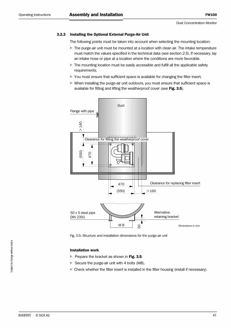
Operating Instructions FW100
Dust Concentration Monitor
Assembly and InstallationSu
bjec
t to
chan
ge w
ithou
t not
ice
3.2.3 Installing the Optional External Purge-Air Unit
The following points must be taken into account when selecting the mounting location:
‡ The purge-air unit must be mounted at a location with clean air. The intake temperature
must match the values specified in the technical data (see section 2.5). If necessary, lay
an intake hose or pipe at a location where the conditions are more favorable.
‡ The mounting location must be easily accessible and fulfill all the applicable safety
requirements.
‡ You must ensure that sufficient space is available for changing the filter insert.
‡ When installing the purge-air unit outdoors, you must ensure that sufficient space is
available for fitting and lifting the weatherproof cover (see Fig. 3.5).
Fig. 3.5: Structure and installation dimensions for the purge-air unit
Installation work
‡ Prepare the bracket as shown in Fig. 3.5.
‡ Secure the purge-air unit with 4 bolts (M8).
‡ Check whether the filter insert is installed in the filter housing (install if necessary).
> 160
(55
0)
Duct
Clearance for replacing filter insert
> 1
40
(550)
Flange with pipe
47
0
Alternative:
retaining bracket50 x 5 steel pipe
DIN 2391
50
470
M 8
Clearance for fitting the weatherproof cover
Dimensions in mm
8008905 · © SICK AG 41

FW100 Operating Instructions
Dust Concentration Monitor
Assembly and Installation
Subj
ect t
o ch
ange
with
out n
otice
3.2.4 Fitting the Weatherproof Covers
Weatherproof cover for analyzer
This weatherproof cover protects the transmitter/receiver unit (see Fig. 2.24). It comprises
a baseplate and cover.
Installation:
‡ Mount the baseplate sideways on the flange with pipe and secure it onto the surface of
the flange plate using the threaded pins (see Fig. 3.6).
‡ Mount the cover from above.
‡ Insert the side lock bolts into the counterparts, and rotate them until they latch into place.
Fig. 3.6: Fitting the weatherproof cover for the analyzer
Weatherproof cover for FWSE/FWR-D housing
This weatherproof cover is secured directly onto the rear of the transmitter/receiver unit and
reflector housing (see Fig. 2.25).
Installation:
‡ Remove the M6 plastic covers.
‡ Screw the spacer pins into the thread openings on the rear of the housing.
‡ Secure the weatherproof cover onto the spacer pins.
Weatherproof cover for external purge-air unit
The weatherproof cover (see Fig. 2.23) comprises a cover and lock set.
Installation:
‡ Mount the lock parts from the lock set on the baseplate.
‡ Fit the cover from above.
‡ Insert the lock bolts into the counterparts sideways, and rotate them until they latch into
place.
Lock bolt
Lifting clearanceCover Baseplate
(492) (365)
(239)> 2
50
(36
0)
Flange with pipe Threaded pin
Duct
Dimensions in mm
42 8008905 · © SICK AG

Operating Instructions FW100
Dust Concentration Monitor
Assembly and InstallationSu
bjec
t to
chan
ge w
ithou
t not
ice
3.3 Installation
3.3.1 General Instructions and Prerequisites
Before you start the installation work, you must have carried out the steps described in
Section 3.2.
Unless otherwise agreed with SICK or an authorized SICK representative, all of the
installation work must be carried out by the customer. This includes laying and connecting
the power supply and signal cables, installing circuit-breakers and power fuses, fitting the
device attachments, and connecting the purge-air supply.
Notes ‡ Ensure the cable cross-sections are of sufficient size (see section 2.5, "Technical Data").
‡ The cable ends with the connector for connecting the transmitter/receiver unit must be
of adequate length.
DANGER
Warning
• All installation work must be carried out in line with the relevant safety regulations and
instructions listed in Chapter 1.
• Suitable measures must be taken to protect against danger.
3.3.2 Connection UnitThe power supply cables (terminals L1, N, and PE) and signal cables (analog output, digital
inputs/outputs) must be connected to the terminal strip as shown in Fig. 3.7.
8008905 · © SICK AG 43

FW100 Operating Instructions
Dust Concentration Monitor
Assembly and Installation
Subj
ect t
o ch
ange
with
out n
otice
Fig. 3.7: Terminal strip connections for the customer wiring
RS 232 connection
Analog output (LiY 2x 0.5 mm² (approx.)
Digital input (maintenance) (LiY 2x 0.5 mm² (approx.)
Digital input (input for synchronization filter bag control
Maintenance
Limit value
Malfunction
115/230 V AC; 50/60 Hz
Terminal strip
White
Bro
wn
Yello
w
Gre
en
Pin
k
Gre
y
Red
Blu
e
Purp
le
Bla
ck
Gre
y/Pin
k
Red/B
lack
White/G
reen
Bro
wn/G
reen
White/Y
ello
w
Bro
wn/Y
ello
w
Bro
wn
Blu
e
Yello
w/G
reen
Signal cablePower
cable
Re
lay
1
Re
lay
2
Re
lay
3
G
nd +
0...
20
mA
–
Dig
in 1
Dig
in 2
RS 232
Txd
Rxd
GndCustomer wiring
RS 232 assignment
Socket
(9 pole)
FW100
Plug
(9 pole)
PC
2 Txd 2 Rxd
3 Rxd 3 Txd
5 Gnd 5 Gnd
Connection units with 24 V DC power supply:
Instead of L1 Instead of N
+ -
Fuse T1A
Shield
44 8008905 · © SICK AG

Operating Instructions FW100
Dust Concentration Monitor
Assembly and InstallationSu
bjec
t to
chan
ge w
ithou
t not
ice
3.3.3 Connecting/Commissioning the Optional External Purge-Air Unit
Activities
‡ Compare the supply voltage and frequency with the specifications on the rating plate of
the purge-air motor.
ATTENTION
Important
Do not connect the purge-air unit if the values do not match.
‡ Connect the power supply cable to the terminals on the purge-air motor (see
supplementary sheet on purge-air motor and cover of motor terminal box; see the
connection arrangement shown in Fig. 3.8).
‡ Connect a protective conductor to the terminal.
If you are in doubt, or if
you are using a special
motor version, the
operating instructions
supplied with the motor
take priority over any
other information.
‡ Set the motor circuit-breakers in accordance with the connection data of the fan (see
technical data of purge-air unit) to a value 10% greater than the rated current.
‡ Check the functioning and running direction of the fan (flow direction of the purge-air unit
must match the arrows at the inlet and outlet openings on the fan). If the direction of
running on 3-phase motors is incorrect, swap power connections L1 and L2.
‡ Connect the (optional) pressure monitor for monitoring the purge-air supply.
Important
ATTENTION
• Use a fail-safe power supply (emergency power supply, bar with redundant supply).
• The purge-air unit must be fused separately from the other system components. The fuse
type must match the rated current (see technical details of purge-air unit). Fuse each
phase separately. Provide circuit-breakers to protect against a phase failure on one side.
Fig. 3.8: Electrical connections for the external purge-air unit
Power supply4 x 1.5 mm2 L1 L1
U1 U1
U1
U1
V1 V1
V1
V1
W1 W1
W1
W1
PE PE
W2 W2
W2
W2
V2 V2
V2V2
U2 U2
U2
U2
L2 L2 + 24 VL3 L3 _PE PE
Low-pressure monitor
8008905 · © SICK AG 45

FW100 Operating Instructions
Dust Concentration Monitor
Assembly and Installation
Subj
ect t
o ch
ange
with
out n
otice
3.3.4 Installing the Purge-Air Supply
‡ Lay the purge-air hoses without kinks along the shortest path (shorten the purge-air
hoses if necessary). Provide sufficient distance from hot duct walls.
‡ Switch on the connection unit with purge-air supply or optional external purge-air unit
(switch on the power supply) and ensure that the purge air is flowing in the right direction.
Connection Unit with Integrated Purge-air Supply
‡ Adjust the purge-air connector according to Fig. 3.9 (FW101) oder Fig. 3.10 (FW102)
(loosen the upper securing screw and rotate the connector correspondingly).
Note At applications with duct inside pressure greater 0 mbar (overpressure), adjust the con-
nector generally in accordance with Fig. 3.10 .
‡ Push the purge-air hoses DN 25 onto the purge-air connector and secure it with the hose
clamp.
Fig. 3.9: Underside of the connection unit with integrated purge-air supply, adjustment for FW101
Fig. 3.10: Underside of the connection unit with integrated purge-air supply, adjustment for FW102
Upper
securing screw
Purge-air outlet
must be closed
with cover
Purge-air outlet
Purge-air connector
Purge-air inlet
Purge-air inlet
Upper
securing screw
Purge-air outlet
must be closed
with cover
Purge-air outlet
Purge-air connector
46 8008905 · © SICK AG

Operating Instructions FW100
Dust Concentration Monitor
Assembly and InstallationSu
bjec
t to
chan
ge w
ithou
t not
ice
Optional External Purge-air Unit
‡ Push the purge-air hoses DN 40 onto the Y distributor of the optional external purge-air
unit and the purge-air reduction, and secure them with hose clamps.
‡ Close the second outlet at the Y distributor of the purge-air unit with the cover.
Fig. 3.11: Connection of the optional external purge-air unit
Note For FWSE101 transmitter/receiver units in high temperature version up to 400 C use the
purge-air reduction installed at the instrument.
Purging with Instrument air
ATTENTION
Important
The instrument air to be provided by the customer must be free of dust, oil, humidity and
condensates!
‡ Choose the reduction nozzle(scope of supply) corresponding to the admission pressure
of the instrument air and screw it into the adapter for instrument air supply.
‡ Connect the instrument air hose to the screw at the adapter.
Note The adapter for instrument air supply can be delivered on request with reducing nipple for
other connection threads.
Fig. 3.12: Connection of the adapter for instrument air supply
Optional external purge-air unit
Cover with opening (part of the purge-air reduction)
Purge-air reduction
Purge-air connector of the transmitter/receiver unit
Reduction nozzle Inner diameter Admission pressure
D3 3 mm 1 ... 3 bar
D2 2 mm 3 ... 6 bar
Reduction nozzle
G 1/4“
Purge-air connector of the transmitter/receiver unit
Connection for instrument air
Purge-air consumption approx. 6 ... 13 m³/h
(depending on admission pressure)
8008905 · © SICK AG 47

FW100 Operating Instructions
Dust Concentration Monitor
Assembly and Installation
Subj
ect t
o ch
ange
with
out n
otice
3.3.5 Connecting Optional Devices
CAN Module and Second Analog Output
The "Maintenance" relay output (relay 3) is not required when the optional CAN module or
second analog output is installed. The cables to the connection unit for the CAN bus or
analog signal are used instead.
Fig. 3.13: Terminal assignment when the optional CAN module or 2nd analog output is installed
Note Instead of relay 3, which is not required, relay 2 can be used to signal the "Maintenance"
operating status (setting in MEPA-FW, see section 4.5.2).
ATTENTION
Important
To ensure that data is transmitted reliably on the CAN bus, you must connect a terminating
resistor to the end of the bus (terminating resistor equal to line impedance value).
RS 232 connection
Analog output (LiY 2x 0.5 mm² (approx.)
Digital input (maintenance) (LiY 2x 0.5 mm² (approx.)
Digital input (input for synchronization filter bag control
115/230 V AC; 50/60 Hz
Terminal strip
White
Bro
wn
Yello
w
Gre
en
Pin
k
Gre
y
Red
Blu
e
Purp
le
Bla
ck
Gre
y/P
ink
Red/B
lack
White/G
reen
Bro
wn/G
ree
n
White/Y
ello
w
Bro
wn/Y
ello
w
Bro
wn
Blu
e
Yello
w/G
reen
Signal cablePower
cable
Rela
y 1
Rela
y 2
G
nd +
0...
20
mA
–
Dig
in 1
Dig
in 2
RS 232
Txd
Rxd
GndCustomer wiring
Fuse T1A
Option CAN
module or 2nd
analog output
Limit value
Malfunction
Option Terminal 15 Terminal 16
CAN module CAN + high CAN - low
2nd analog output + -
Connection units with 24 V d.c. power supply:
Instead of L1 Instead of N
+ -
RS 232 assignment
Socket
(9 pole)
FW300
Connector
(9 pole)
PC
2 Txd 2 Rxd
3 Rxd 3 Txd
5 Gnd 5 Gnd
Shield
48 8008905 · © SICK AG

Operating Instructions FW100
Dust Concentration Monitor
Assembly and InstallationSu
bjec
t to
chan
ge w
ithou
t not
ice
Evaluation Unit EVU
EVU at the bus end
Fig. 3.14: Connection of the optional EVU
H L
H L
CAN 1
CAN 1
15 16
15 16
15 16
15 16
15 16
15 16
EVU
Connection unit
FW100
(Connection unit
FW100)
(Connection unit
FW100)
Terminating resistor
(value equal to line impedance)
Terminating resistor of the EVU
(realized by a jumper)
Connect the terminating
resistor in the connection
unit which is removed
from the EVU furthest.
EVU in the middle of the bus
Connection unit
FW100
(Connection unit
FW100)
(Connection unit
FW100)
Connect the terminating
resistors in the connection
units which are removed
from the EVU furthest
The terminating resistor
of the EVU is not needed
(remove the jumper)
If only one FW100 is connected to the EVU, the terminating resistors must be con-
nected in the EVU and connection unit.
The terminating resistors in the connection units have to be supplied by the customer.
8008905 · © SICK AG 49

FW100 Operating Instructions
Dust Concentration Monitor
Assembly and Installation
Subj
ect t
o ch
ange
with
out n
otice
LCD
If the optional LCD is installed, the terminal strip in the connection unit for the customer
wiring (see Fig. 3.7) is replaced by an additional board with terminals to which the cables
for the analog and status signals are attached as shown in Fig. 3.15.
Fig. 3.15 Terminal assignment with optional LCD
Fig. 3.16: Signal cable connection
Analog output
Malfunction
Option CAN module
or 2nd analog
output
Limit value 1Digital input (maintenance)
115/230 V AC; 50/60 Hz
Connections for the signal cables to the T/R unit
Re
lay
1
R
ela
y 2
G
nd +
0...
20
mA
–
Dig
in 1
Dig
in 2
RS 232
Txd
Rxd
Gnd
Customer wiring
RS 232 connection
(Assignment as shown in Fig. 3.7) Board
Terminal block 2
Connection for shield
Terminal block 1
Re
lay
4
Re
lay
5
Re
lay
6
Check
cycle
Maintenance
Limit value 2
Option Terminal 15 Terminal 16
CAN module CAN + high CAN - low
2nd analog output + -
Connection units with 24 V DC power supply:
Instead of L1 Instead of N
+ -
Shield
Digital input (input for synchronization filter bag control)
White
Bro
wn
Ye
llow
Gre
en
Pin
k
Gre
y
Re
d
Blu
e
Purp
le
Bla
ck
Gre
y/P
ink
Re
d/B
lack
White
/Gre
en
Bro
wn/G
ree
n
White
/Ye
llow
Bro
wn/Y
ello
w
Scre
en
Board
Signal cable
50 8008905 · © SICK AG

Basics
Installing and Connecting the Transmitter/Receiver Unit
Parameterization
Parameterizing Optional Devices
FW100
Dust Concentration Monitor
Commissioning and Parameterization


Operating Instructions FW100
Dust Concentration Monitor
Commissioning and ParameterizationSu
bjec
t to
chan
ge w
ithou
t not
ice
4 Commissioning and Parameterization
4.1 Basics
4.1.1 General Notes
Commissioning the FW100 involves the following steps:
‡ Mounting the transmitter/receiver unit at the duct.
‡ Customer-specific parameterization in accordance with requirements.
If the FW100 is to be implemented for continuously measuring dust content, it must be
calibrated using a gravimetric comparison measurement to ensure accurate measurements
(see Section 4.4).
The process of setting options in accordance with Section 2.3.6 is described in Section 4.5.
The MEPA-FW parameterization program is shipped with the device. The required settings
can be easily configured using the program menus. Other functions (such as data storage
and graphic display functions) are also available.
Certain instrument functions can only be accessed once you have entered a password (see
appendix). The access rights are assigned in 3 stages:
4.1.2 Prerequisites
‡ Laptop/PC with:
– Processor: Pentium 2 or higher
– VGA graphics card
Pin assignment – Serial interface COM 1 or COM 2
– Main memory (RAM): minimum 32 MB
– Operating system: Microsoft Windows 95 or higher
‡ Interface cable (serial cable; see Options, Section 8.2) for connecting a laptop/PC to the
FW100.
‡ The MEPA-FW operating and parameterization program must be installed on the laptop/
PC. To install the program, insert the disk/CD supplied into your disk/CD drive, call up the
corresponding drive, run the "mepa-fw_setup.exe" file, and follow the instructions.
‡ The power supply must be connected.
Level Password Access to
"User" none Measured value displays, device status query, display/output
parameter log; parameterization not possible
"Authorized
user"
Level 1 Displays, queries, and parameters for commissioning and
customizing.
"Service" Level 2 Displays, queries, and all parameters.
For performing all on-site service activities (for example,
diagnosis and troubleshooting).
RS 232
socket in
connection
unit
PC
connector,
9 pole
Pin 2 (txd) Pin 2 (rxd)
Pin 3 (rxd) Pin 3 (txd)
Pin 5 (gnd) Pin 5 (gnd)
8008905 · © SICK AG 53

FW100 Operating Instructions
Dust Concentration Monitor
Commissioning and Parameterization
Subj
ect t
o ch
ange
with
out n
otice
4.2 Installing and Connecting the Transmitter/Receiver Unit
First ensure that the assembly element for transmitter/receiver unit has been mounted at
the duct (see Section 3.2.1) and the purge-air supply is in operation (insure that the flow
direction is correct and the purge-air hoses are securely attached to the connector).
4.2.1 Aligning the Transmitter/Receiver Unit
The transmitter/receiver unit (FWSE 101, FWSE 102) must be aligned in the duct so that
the particle loaded gas can flow unhindered through the measuring volume.
To ensure that the labeling on the cover of the transmitter/receiver unit is clearly legible, the
cover should rotate through 90 ° in case of mounting the transmitter/receiver unit at a
vertical duct (loosen the securing screws, rotate the cover according to Fig. 4.1 or Fig. 4.2
and remount it again).
FWSE101 Alignment
Fig. 4.1: FWSE101 alignment
Notes • To prevent the device from being aligned incorrectly the next time it is mounted (e.g. after
maintenance), the holes on the bayonet catch that are not required should be sealed
using the cover supplied.
• Use the optional elbow plug in case of mounting the transmitter/receiver unit in a vertical
duct and using the weatherproof cover for the analyzer (see Section 2.3.8).
Horizontal duct Vertical duct
Flow
direction Flow
direction
Cover
Option
Elbow
plug
Connector
Cover of the electronic unit
rotated through 90 °
54 8008905 · © SICK AG

Operating Instructions FW100
Dust Concentration Monitor
Commissioning and ParameterizationSu
bjec
t to
chan
ge w
ithou
t not
ice
FWSE102 Alignment
Fig. 4.2: FWSE102 alignment
4.2.2 Starting up the Transmitter/Receiver Unit
‡ Connect the transmitter/receiver unit type FWSE101 and FWSE102 Tri-Clamp® to the
purge-air supply. Depending of the direction of the supply, practice the following:
– Connection unit with integrated purge-air supply:
Push the purge-air hose DN 25 onto the purge-air nozzle of the transmitter/receiver
unit and secure it with a hose clamp.
– Optional external purge-air unit:
Push the purge-air hose DN 40 onto the purge-air reduction and then the reduction
onto the purge-air nozzle of the transmitter/receiver unit, and secure hose and reduc-
tion with a hose clamp (see Fig. 3.11.).
Note For FWSE101 transmitter/receiver units in high temperature version up to 400 °C use
the purge-air reduction installed at the instrument.
– Instrument air supply:
Connect the instrument air hose to the adapter for instrument air supply (see Fig. 3.12), push the adapter onto the purge-air nozzle of the transmitter/receiver unit and
secure it with a hose clamp.
‡ Install the transmitter/receiver unit in the duct.
– FWSE101:
Insert it unit into the flange and secure it with the 3 nuts of the flange/reflector
installation set (see Section 8.1.5).
– FWSE102 Tri-Clamp® version:
Insert it in the right alignment into the Tri-Clamp® flange and secure it with the fitting.
– FWSE102 1“ version: Screw it in the 1“ sleeve, align it according to Fig. 4.2 and fix it
with the locknut. Immediately after this connect the transmitter/receiver unit to the
purge-air supply as described below.
‡ Connect the signal cable to the connection unit tightly to the connector (or elbow plug).
Horizontal duct Vertical duct
Flow
direction
Flow
directionOption
Elbow
plug
Connector
Cover of the electronic unit
rotated through 90 °
8008905 · © SICK AG 55

FW100 Operating Instructions
Dust Concentration Monitor
Commissioning and Parameterization
5
4.3 Connecting the Device
‡ Connect the interface cable to the connection unit and laptop/PC.
‡ Start the "MEPA-FW.EXE" operating and parameterization program.
‡ The "Connection" menu appears on the screen.
Fig. 4.3: „Connection“ menu
‡ Enter password level 1 (only necessary if parameters have to be changed).
‡ Connect to the FW100.
Choose the serial interface on the PC (e.g. COM 1) and click "Connection". The active
parameter set for the device is then imported to MEPA-FW.
Note You cannot connect to the device while the system is calculating the check values during
a check cycle (duration max. 40 s; the information is displayed in a separate window).
Once you have successfully connected to the device, the start menu is displayed and shows
a graphical representation of the measured values, system state, and analog value(s).
Fig. 4.4: MEPA-FW start menu
‡ If necessary, change the language setting under "Options / Language".
Menu bar
Status bar
Desktop
Tab page
Displayed only with 2nd analog output
option
Current measured valuet
Subj
ect t
o ch
ange
with
out n
otice
6 8008905 · © SICK AG

Operating Instructions FW100
Dust Concentration Monitor
Commissioning and ParameterizationSu
bjec
t to
chan
ge w
ithou
t not
ice
4.4 Parameterization
The FW100 is shipped with default settings (see Fig. 4.5). The standard values are
enclosed in the parameter log. You can also view these settings on the "Protocol" tab page
in MEPA-FW.
If you do not have to change these settings, you can use the FW100 in your installation
straight away.
4.4.1 Customer-Specific Parameterization
If you do have to change the parameters, set the password level 1 (see Section 4.1.1) once
the connection to MEPA-FW has been established, and activate "Maintenance" mode
(menu "Operating mode / Maintenance" or with external maintenance switch at the
terminals for the digital input Dig in 1). The device status is displayed in the „Measured values“ tab page by shining the system state LED „Maintenance“ (when the status is set via
MEPA-FW, the addition „(SOFT)“ for software setting is signaled). Then choose the "Parameter" tab page (see Fig. 4.5).
Fig. 4.5: "Parameter“ tab page
"Signal calculation" field
‡ Response time t90 (see Section 2.2.2)
Enter a value between 0.1 s and 600 s in the relevant field (in the format: XXX.XX).
Note The t90 time setting affects the response behavior of the measured value and the output
of analog values and the limit value relay. If you enter a high t90 time, the limit value relay
does not respond to transient, high measured value peaks. At low t90 times , the
response behavior of the FW100 is extremely quick (noise is greater).
8008905 · © SICK AG 57

FW100 Operating Instructions
Dust Concentration Monitor
Commissioning and Parameterization
Subj
ect t
o ch
ange
with
out n
otice
‡ Calibration function
To realize the correlation between the primary measured variable scattered light intensity
and the dust concentration in the duct as exactly as possible, a regression function is in-
stalled in the field “Calibration function“. This function can be set as a quare or linear func-
tion. A total of 4 coefficient sets are supplied:
In the coefficient set 0 the regression coefficients can entered as required. This set has
to be selected if the FW100 must be calibrated to measure the dust concentration.
The coefficient sets 1 – 3 cannot be modified. The corresponding default set is activated
when you select one of these coefficient sets. You can use them if a maximum level of
precision is not essential. These sets are based on SICK’s extensive experience.
Note The regression coefficients of set 1 - 3 refer to dusts with a mean density of 2,5 g/m³, approximately spherical grain structure and even distribution of the dust in the duct cross-
section.
"Output" field
The current output and limit value relay is set in this field.
‡ Analog output
– Live Zero (LZ)
You can set the zero point to 0.2, or 4 mA.
Recommendation This value should ideally be set to 2 or 4 mA to differentiate between the measured
value and when the device is switched off or the power supply is interrupted.
– Measuring range (MR)
You must enter the lower MR limit for LZ and the upper MR limit for 20 mA.
‡ Limit value
Enter a value below or above which (depending on the selected measured variable) the
limit value relay is to drop out. The limit value relay has a hysteresis equal to 10 % of the
defined limit value.
Set Setting of the regression
coefficients
Typical application Regression coefficients
square linear absolute
Set 0 freely selectable all 0 1 0
Set 1 fix; for small particle sizes
(average size 2 µm)
downstream of
cloth filter systems
0 0,5 0
Set 2 fix; for medium particle
sizes (average size 5 µm)
downstream of
electrostatic preci-
pitators
0 2 0
Set 3 fix; for big particle sizes
(average size 10 µm)
downstream of
coarse filters (cyc-
lone dust separa-
tors)
0 3 0
58 8008905 · © SICK AG

Operating Instructions FW100
Dust Concentration Monitor
Commissioning and ParameterizationSu
bjec
t to
chan
ge w
ithou
t not
ice
"Check cycle" field
The check cycle is activated by default and the cycle time is set to 8 hours. You can
deactivate it by deselecting the "Enable" checkbox.
‡ Define the cycle time
In the "Interval" window, enter the time between the start of one check cycle and the next
check cycle (range: between 2 and 24 hours).
‡ Output at analog output
When you activate the "Check values analog output" checkbox, the check values
calculated during the cycle check are output at the analog output (see section 2.2.3).
Notes • Each time you switch on the device, and when the device exits "Maintenance" mode, a
check cycle is triggered after 60 s and the check cycle time begins again.
• An automatic check cycle is not triggered if the FW100 is in "Maintenance" mode at the
starting time.
ATTENTION
Important
• After entering of the parameters these must be transferred to the FW100. To do this,
press the button „Write to device“.
• If you change to another tab page before the parameter are transferred to the FW100,
the parameters set before parameterization remain valid.
4.4.2 Calibration for Dust Concentration Measurement
To measure the dust concentration exactly, the correlation between the primary measured
variable scattered light intensity and the actual dust concentration in the duct must be
established. For this purpose, the dust concentration must be determined by means of a
gravimetric measurement to VDI 2066 or ISO 9096 and compared to the scattered light
intensity values measured simultaneously by the FW100.
Required steps
The steps described here
will help you avoid making
input errors. Comparison
measurements require
special knowledge that
cannot be described in
detail here.
‡ Check whether the regression coefficients cc2 = 0, cc1 = 1, cc0 = 0 are set in the MEPA-
FW (if not, correct them accordingly). The measured scattered light intensity is directly
assigned to the mA value as a mg value at the analog output.
‡ Estimate the necessary measuring range and enter it in the "Parameter" tab page (see
Fig. 4.5).
‡ Carry out the gravimetric measurement to VDI 2066 or ISO 9096.
‡ Determine the regression coefficients
First, determine the correlation between the gravimetrically measured dust
concentrations and the mA values of the FW100.
c = K2 · I out² + K1 · Iout + K0 (1)
c: dust concentration in mg/m³K2, K1, K0: regression coefficients of the function c = f (Iout )
Iout: current output value in mA
8008905 · © SICK AG 59

FW100 Operating Instructions
Dust Concentration Monitor
Commissioning and Parameterization
Subj
ect t
o ch
ange
with
out n
otice
Iout = LZ + SI · (2)
SI = measured scattered light intensity value
LZ = Live Zero
URL = defined upper range limit (entered value for 20 mA;
normally 2.5 x fixed limit value)
‡ Enter the regression coefficients
There are two possibilities:
– Direct input of K2, K1, K0 into a measurement computer.
The coefficient set and measuring range entered in the FW100 will not be changed
any more.
– Use of the FW100 regression function (no measurement computer necessary).
In this case the correlation to the scattered light intensity has to be determined. To do
so, the regression coefficients cc2, cc1, cc0 to be entered in the FW100 have to be
calculated from K2, K1, K0.
c = cc2 · SI² + cc1· SI + cc0 (3)
By using (2) in (1), the result is as follows:
c = K2 · (LZ + SI · ) + K1 · (LZ + SI · )+ K0
Using (3), the result is as follows:
cc2 = K2 · ( )
cc1 = (2 · K2 · LZ + K1) ·
cc0 = K2 · LZ2 + K1 · LZ + K0
‡ Enter regression coefficients cc2, cc1, and cc0 in the FW100.
Notes • A special program is available for calculating the regression coefficients.
• If a data memory / event memory is available, the FW100 measured values can be saved
as a file, from which the coefficients can be determined in MS Excel.
• If the new regression coefficients cc2, cc1 and cc0 are entered into the FW100 (but not
into a measurement computer), the analog output parameterization can be changed in
every way.
4.4.3 Filter Bag Control
The FW100 can be used to locate defective filter bags in cyclically cleaned hose or other
filter installations consisting of several individual filters (filter bags).
The check is carried out by continuously evaluating the cleaning peaks of all the filter bags
in a cleaning cycle. If the current filter value exceeds the limit value set in the FW100, the
limit value violation is assigned to the filter in question by means of an internal counter.
20 mA - LZ
URL
20 mA - LZ
URL
20 mA - LZ
URL
20 mA - LZ
URL
20 mA - LZ
URL
2
2
60 8008905 · © SICK AG

Operating Instructions FW100
Dust Concentration Monitor
Commissioning and ParameterizationSu
bjec
t to
chan
ge w
ithou
t not
ice
To use this feature, the following prerequisites must be available:
• Debounced synchronization signal of 25 … 900 ms for triggering a measurement cycle.
This synchronization signal must be provided by the plant operator and applied to
terminals 10 (DIG IN2) and 4 (GND) in the FW100 connection unit (e.g. connect terminals
10 and 4 with a relay contact).
• The time between the cleaning cycles of two consecutive filter bags must be greater than
twice the t90 time of the FW100, and equal to at least 2 sec.
Parameterization
Open the „Filterwatch“ tab page and activate the button „Stop“ (the „Measure“ mode is
automatically set when opening the tab page).
Fig. 4.6: „Filterwatch“ tab page
To assign the current measured value or limit value violation to a filter bag, enter the fol-
lowing parameters (see Fig. 4.6):
Adjustment range in bra-
ckets before the re-
spective input field
• Input field "Cleaning impulses": Number of filter groups to be cleaned in a cycle
• Input field „Delay": Delay between the synchronization signal and
the time at which the dust clouds reach the
measuring site
• Input field "Impulse interval": Time that elapses before the next filter bag is
cleaned.
Measuring window
Event table
Counter for limit value violations Maximum measuring value
8008905 · © SICK AG 61

FW100 Operating Instructions
Dust Concentration Monitor
Commissioning and Parameterization
Subj
ect t
o ch
ange
with
out n
otice
4.4.4 Data Backup
In some cases, you may have to reconfigure the parameter settings. You have the following
possibilities for the registration necessary for it:
‡ Print out the parameter log ("Protocol" tab page , button "Print protocol"; see Fig. 4.7)
and keep it with your documentation on the instrument.
Prerequisite: A printer has to be avalilable at the measuring site.
‡ Save the parameter log into a file (button "Save to file", define a new name if necessary).
This can be reloaded (button „Load from file“) and printed at a later time again. The
FW100 need not be connected to do so (select „Connection“ menu, interface „Simulati-
on“).
The parameter log can also be useful for determining the cause of malfunctions (send the
log to SICK).
Fig. 4.7: Parameter log (example)
Notes • The value shown on the field "Status code“ serves for the evaluation by the manufacturer
in the case of device malfunctions. If you want to analyze the instrument status, please
change to the "Diagnosis/Test" tab page. Possible messages displayed there and
corrective measures are described in Section 6.2.
• The device protocol can be changed also into a text file (ASCII format) and then edited
using any editor or text program. To do this, press the button “Print protocol“ and activate
the checkbox “Print to text file“ in the “Printer selection“ menu (see Fig. 4.8).
62 8008905 · © SICK AG

Operating Instructions FW100
Dust Concentration Monitor
Commissioning and ParameterizationSu
bjec
t to
chan
ge w
ithou
t not
ice
Fig. 4.8: „Printer selection“ menu
4.4.5 Starting Standard Measuring Mode
Standard measuring mode is started when you switch to "Measure" mode ("Operation mode / Measure" menu). This completes the standard commissioning procedure. The
measured values are displayed graphically on the "Measured values" tab page in MEPA-FW
and as a current value of the analog output (see Fig. 4.9).
Fig. 4.9: "Measured values" tab page
Notes • You can change the resolution of the displayed measured values in the "Diagram scale"
field by resetting the value in the "Peak auto scale" and entering a value between 1 and
10000 in the "Maximum" field.
• The instrument also switches to measuring mode when you close the MEPA-FW
operating and parameterization program. If “Maintenance“ mode has been set, the
FW100 automatically switches to "Measure".
• A check cycle is automatically triggered 1 min after the system has switched to measuring
mode.
• The current measuring values are displayed in the diagram when a check cycle is carried
out or if the FW100 is set into “Maintenance“ mode. Conversely, the check values are
given out at the analog output (if so parameterized, see Section 4.4.1) or the live zero
value in status maintenance.
8008905 · © SICK AG 63

FW100 Operating Instructions
Dust Concentration Monitor
Commissioning and Parameterization
Subj
ect t
o ch
ange
with
out n
otice
4.5 Parameterizing Optional Devices
This section describes the settings required for the data memory / event memory, CAN
module, second analog output, and LCD options. Before you can enter or change the
parameters, you must switch to "Maintenance" mode and enter the relevant password.
Note The respective option must be installed in the factory (indicate it at ordering). Retrofitting is
only possible by the manufacturer.
4.5.1 Data Memory / Event Memory
The data is saved by additional hardware in the transmitter/receiver unit and activated by a
release code entered by the manufacturer. If these prerequisites exist and the system has
been connected, the data memory / event memory is available on the "Data memory / event memory" tab page.
Fig. 4.10: "Data memory / Event memory" tab page
Notes • The measured value and event table displays a maximum of 10 values/events along with
their date and time. If more exist, you can go to the required area by scrolling through the
table.
• In the measured value display, you can activate/deactivate the zoom function in the
center of the screen to choose all of the measured values that have been saved or just
those visible in the measured value table. You can scroll through the zoom area in the
table in the same way.
• When you call up this tab page, the column headers in the event table are always
displayed in abbreviated form. You can click the column header to display them in their
full form (column becomes wider), which enables you to see what each column indicates.
Measured value table
Graphical display of
measured values
Zoom option
Zoom area
Event table
Events Centralized malfunctionIndividual faults
System mode-dependent
display
64 8008905 · © SICK AG

Operating Instructions FW100
Dust Concentration Monitor
Commissioning and ParameterizationSu
bjec
t to
chan
ge w
ithou
t not
ice
• The "Erase data memory" and "Erase event memory" buttons are only displayed when
the password is set (inactive display). The system must be in "Maintenance" mode for
active use.
Data memory
The measured value is averaged over the set period, whereby the current measured value
is totaled every 500 ms and, after the time interval has elapsed, the sum is divided by the
number of times it has been totaled. A prerequisite here is that no faults are present and
the system is not in maintenance mode. The resulting average value is not written to the
data memory, however, until the current measured values have been valid for at least 2/3
of the time interval, that is, the total sum of the times for "Maintenance", "Malfunction", or
check cycle was less than 1/3 of the time interval.
You can set or change the interval period for saving the measured values in the "Option
memory measurement value/save interval" field on the "Parameter" tab page within a
range of 1 s to 2 h (see Fig. 4.11).
Fig. 4.11: Setting the storage intervals
Event memory
The following events are registered in this memory:
• When they occur (= 1):
– Start...=Device restart (reset)
– Mea...= Data memory deletion
– Eve... = Event memory deletion
• At start ( = 1) and end (= 0)
– Wro.. = Wrong file format
– Limit...= Limit value violation
– War... = Warning contamination
– Mai... = Maintenance
– M=... = Centralized malfunction
set/reset when one of the following faults is present / no longer present
- M1... = Device temperature > 75 °C- M2... = Span test not successful
- M3... = Monitor signal too low
- M4... = Real-time clock has failed
- M5... = Contamination > 70 %
- M6... = Trigger level check cycle
- M7... = Measured value override
- M8... = EEPROM check sum
- M9... = Communication with display
8008905 · © SICK AG 65

FW100 Operating Instructions
Dust Concentration Monitor
Commissioning and Parameterization
Subj
ect t
o ch
ange
with
out n
otice
Description
Note The "Save to file" and "ASCII export" functions can only be used if measured values or
events have already been read.
Function Description
"Read data memory" • When you press the "Read data memory" button, the measured values stored in the
connected FW100 are displayed in tabular and graphical form. Up to 7,280 measured values
can be displayed.
• The time range starts with the first measured value interval read and ends with the storage
time of the last (current) measuring interval. If (o) (=overflow) appears at the end of the row,
the data memory has overflowed at least once since it was last cleared.
• The time information for the measured values in the table always relates to the end of an
averaging interval (the storage time).
• If the cyclic backup was interrupted (power off, maintenance), the next measured value is
assigned a new time stamp. In this case, the row may not appear in full in the table.
"Erase data memory" The data memory is deleted after you have confirmed the system prompt. This function is only
available in "Maintenance" mode after you have entered your password.
Important
The data memory is also cleared if you change the set storage interval time ("Parameter" tab
page).
"Read event memory" • When you press the "Read event memory" button, the events stored in the connected
FW100 are displayed in tabular and graphical form. Up to 100 events can be displayed.
• The time range starts with the first event read and ends with the storage time of the last
(current) event.
• The time information for the measured values in the table always relates to the storage time.
"Erase event memory" The event memory is cleared after you have confirmed the system prompt. This function is only
available in "Maintenance" mode after you have entered your password.
"Load from file" You can choose and read a measured value file (*.dat) or event file (*.eve) stored in the system
(separate MEPA format).
"Save to file" The measured values or events displayed are store in a measured value or event file (separate
MEPA format).
"ASCII export" The measured values or events displayed can be stored in an ASCII file (*.txt). The data can
then, for example, be processed subsequently for a graphical analysis in a spreadsheet
program (such as Excel) or processed for logging purposes in a word processing program.
Important
The ASCII file cannot be re-read by MEPA-FW!
66 8008905 · © SICK AG

Operating Instructions FW100
Dust Concentration Monitor
Commissioning and ParameterizationSu
bjec
t to
chan
ge w
ithou
t not
ice
Setting the real-time clock
The FW100 has a battery-buffered real-time clock that is set by the manufacturer before
shipment. If required, this clock can be synchronized with the system time of a connected
PC. Ensure that the clock in the PC has the right date (year numbers from 2000 [00] to
2066 [66] only).
To set the clock, press the "Set with PC time" button in the "Option memory measurement
value" field on the "Parameter" tab page in MEPA-FW (see Fig. 4.12). This sets the device-
internal clock to the time and date of the connected PC.
ATTENTION
Important
Changing the time or date does not automatically reset the data memory / event memory,
which means that time ranges may occur twice or gaps may exist in the relevant memories.
4.5.2 CAN Module
An address must be assigned to the FW100 so that it can communicate with the evaluation
unit. Enter this in the "Option CAN-Bus" on the "Parameter" tab page (see Fig. 4.12). The
address can be set in a range of 73 to 127.
Fig. 4.12: Parameterizing optional devices
For communication between FW100 and evaluation unit, only the addresses 73, 74 and 75
are selectable. The assignment to the connected FW100 is displayed on the LCD of the eva-
luation unit in the following way:
• FW_1: FW100 with address 73
• FW_2: FW100 with address 74
• FW_3: FW100 with address 75
Only displayed if the
option is installed
8008905 · © SICK AG 67

FW100 Operating Instructions
Dust Concentration Monitor
Commissioning and Parameterization
Subj
ect t
o ch
ange
with
out n
otice
4.5.3 Second Analog Output
You can set the required measuring range in the "Option measurement range analog output
2" field on the "Parameter" tab page (see Fig. 4.13). The range limits are set in the same
way as for the standard output (see section 4.4.1).
The standard output values apply for live zero.
Since the lines for relay 3 are used for this option (see also Section 3.3.5), relay 2 can be
set to signal either maintenance mode or the limit value. You make the assignment in the
"Relay 2 signals“ field by choosing the appropriate checkbox.
Fig. 4.13: Parameterizing option 2 (analog output and LCD)
4.5.4 LCD
This option enables you to define a second limit value. Enter the value in the "Option limit
value 2" field on the "Parameter" tab page (see Fig. 4.13).
No further parameterization is required.
Only displayed
if the option is
installed
68 8008905 · © SICK AG

Operating Instructions FW100
Dust Concentration Monitor
Commissioning and ParameterizationSu
bjec
t to
chan
ge w
ithou
t not
ice
4.5.5 ASC Option (Automatic Self Control, only for FW102)
Using this option, the FW102 can be checked for proper device function. To do this, enter
the supervision time interval between 0 and 45 hours and the difference limit between the
highest and lowest measuring value in a range of 0.1 to 1000 mg/m³ in the „ASC - Automa-
tic Self Control“ field on the “Parameter“ tab page (see Fig. 4.14).
The device works normal if the difference value was exceeded at least once in the set time
intervall. Otherwise a malfunction message appears (“Automatic Self Control“, see Section
6.2.2).
Fig. 4.14: „Parameter“ tab page (only for FW102)
Notes • If the difference value was exceeded in a time interval, a new one is automatically started
as well after changing the check values.
• The ASC option is deactivated by entering of zero for the difference limit.
8008905 · © SICK AG 69

FW100 Operating Instructions
Dust Concentration Monitor
Commissioning and Parameterization
Subj
ect t
o ch
ange
with
out n
otice
70 8008905 · © SICK AG
General
Maintaining the Transmitter/Receiver Unit
Maintaining the Purge-Air Supply
Removal from Service
FW100
Dust Concentration Monitor
Maintenance


Operating Instructions FW100
Dust Concentration Monitor
MaintenanceSu
bjec
t to
chan
ge w
ithou
t not
ice
5 Maintenance
5.1 General
The FW100 is designed for long-term and nearly maintenance-free operation. You simply
have to ensure that the optical boundary surfaces are clean and the purge-air supply is
functioning properly.
Before you carry out these maintenance tasks, you have to set the FW100 to
"Maintenance" mode. You can do this by connecting the digital input Dig in 1 (terminals 4,
9; see Fig. 3.7/Fig. 3.13/Fig. 3.15) externally on the hardware side, or by choosing
"Operating mode / Maintenance" in the MEPA-FW menu on the software side.
Once you have completed these activities, switch the system back to measuring mode
(switch off the external maintenance switch or choose "Measure" in the "Operating mode"
menu).
Note • When the maintenance switch is set, warning and fault messages are suppressed. The
live zero value is given out at the analog output.
• If the FW100 was set into "Maintenance" mode via MEPA-FW („Software maintenance“),
this status is reset at a voltage loss (in this case the FW100 switch automatically into
„Measurement“ after the operating voltage is switched on).
• If „Maintenance“ is set by an external switch, the FW100 remains in this status as long
as the contact is closed at the terminals 4, 9.
Maintenance intervals
The plant operator is responsible for defining the maintenance intervals. This will depend on
specific operating parameters, such as dust content and type, gas temperature, plant
operational procedures, and ambient conditions. For this reason, only general
recommendations can be provided here. The maintenance intervals are normally in the
starting time approx. 4 weeks for the FW101 and approx. 2 weeks for the FW102, and can
gradually be prolonged up to a year if the corresponding conditions are available. The
activities required and their completion must be documented by the operator in a
maintenance log.
Maintenance agreement
Regular maintenance activities can be carried out by the plant operator. These activities
must be carried out by qualified persons (as described in Chapter 1) only. If requested, all
maintenance activities can also be performed by the SICK Service department, or an
authorized service partner. SICK offers a range of economical maintenance and repair
agreements. SICK undertakes all maintenance and servicing work specified in these
agreements. Wherever possible, specialists carry out repairs on site.
DANGER
Warning
All installation work must be carried out in line with the relevant safety regulations and
instructions listed in Section 1.3 (especially Section 1.3.3).
8008905 · © SICK AG 73

FW100 Operating Instructions
Dust Concentration Monitor
Maintenance
Subj
ect t
o ch
ange
with
out n
otice
5.2 Maintaining the Transmitter/Receiver Unit
DANGER
Warning
• Make sure that none of the components or accessories of the FW100 are damaged
when performing maintenance work on.
• The purge-air supply must not be interrupted.
Required tools:
• Brush, cloth, cotton buds,
• Water,
• Compressed air (dust and oil free; e.g. compressed air in 200 to 500 ml spray cans),
• A blind plug for the device attachment (if required).
5.2.1 Cleaning the Transmitter/Receiver Unit (Externally)
Clean the outside of the FW100 transmitter/receiver unit (particularly the measuring probe)
at regular intervals. Remove deposits with water or suitable mechanical aids.
To clean the transmitter/receiver unit remove it from the duct in the following way:
‡ For FW101 loosen the securing nuts.
‡ For FW102 in Tri-Clamp® version loosen the Tri-Clamp®-Fitting.
‡ For FW102 in 1“version loosen the locknut and remove the purge-air connection.
‡ Pull or turn out (FW102 1“) the transmitter/receiver unit.
After cleaning the transmitter/receiver unit install it in the duct.
5.2.2 Cleaning the Optical Boundary Surfaces
The "optical boundary surface" is the surface of the optics or glass that faces the duct.
The optical boundary surfaces of the T/R unit only require cleaning if they are visibly dirty or
if the current degree of contamination is reached and is monitored by FW101; limit 50 %
for warning, 70 % for malfunction).
Procedure
‡ Remove the transmitter/receiver unit from the duct.
‡ Unscrew the cap (black) on the cleaning opening; for FW101 also the cover at the top of
the probe.
‡ Clean the optics carefully with cotton buds, also the light trap if necessary (see Fig. 5.1
bzw. Fig. 5.2).
‡ Reassemble the transmitter/receiver unit and install it in the duct.
Note We recommend to check the the laser beam alignment in connection with cleaning of the
optical boundary surfaces (see Section 6.3.1).
74 8008905 · © SICK AG

Operating Instructions FW100
Dust Concentration Monitor
MaintenanceSu
bjec
t to
chan
ge w
ithou
t not
ice
Fig. 5.1: Cleaning the optical boundary surfaces for FW101
Fig. 5.2: Cleaning the optical boundary surfaces for FW102
Note To clean the light trap for FW102, remove the cover and the small pipe.
Cleaning opening for transmitter optics Protection tube
Cap
Transmitter
optics
Cover
Receiver optics Light trap
Cover
(Small pipe )
Transmitter
optics Receiver optics
Cleaning opening for
transmitter optics
Light trap
8008905 · © SICK AG 75

FW100 Operating Instructions
Dust Concentration Monitor
Maintenance
7
5.3 Maintaining the Purge-Air Supply
You must carry out the following maintenance activities:
• Inspect the entire purge-air supply
• Clean the filter housing
• Replace the filter insert (if necessary)
The dust load and wear on the filter insert depend on the degree of contamination of the
ambient air that is drawn in. For this reason, we cannot provide specific recommendations
regarding maintenance intervals, although you are advised to inspect the purge-air unit in
short intervalls (approx. 2 weeks) after commissioning. The maintenance intervals can then
be optimized accordingly.
ATTENTION
Important
• If the purge-air supply is not maintained at regular intervals or maintenance is not
thorough enough, it can fail and destroy the transmitter/receiver unit.
• You must ensure that the purge-air supply is functioning properly when the transmitter/
receiver unit is installed. When replacing a damaged purge-air hose, you must remove the
transmitter/receiver unit beforehand (see section 5.4).
Inspection
‡ Check the running noise of the fan at regular intervals; an increased noise level can
indicate a fan failure.
‡ Check that all the hoses are secure and free of damage.
‡ Check the filter insert for contamination.
You must replace the filter insert when:
– a high degree of contamination is visible on the filter surface
– the purge-air quantity is considerably less than during operation with a new filter
Note You must not switch off the purge-air supply when cleaning the filter housing or replacing
the filter insert, which means that the transmitter/receiver unit do not have to be removed
from the duct.
Subj
ect t
o ch
ange
with
out n
otice
6 8008905 · © SICK AG

Operating Instructions FW100
Dust Concentration Monitor
MaintenanceSu
bjec
t to
chan
ge w
ithou
t not
ice
5.3.1 Connection Unit with Integrated Purge-Air Supply
Cleaning or replacing the filter insert
‡ Open the door of the connection unit using the appropriate key.
‡ Remove the clamping tape at the filter output (1) and remove the filter from the gland (2).
‡ Remove the filter housing.
‡ Turn the filter housing cover in the direction of the arrow to "OPEN" and remove it.
‡ Remove the filter insert and replace it with a new one.
‡ Clean the filter housing and housing cover with a cloth and brush.
ATTENTION
Important
You must only use a cloth soaked in water to wet-clean the components. Make sure that
you dry the components thoroughly.
Spare part:
Filter insert C1140,
Part no. 7047560
‡ Insert the new filter insert.
‡ Replace the filter housing cover and turn it against the direction of the arrow until it clicks
into position.
‡ Place the filter housing back into the connection unit.
Fig. 5.3: Changing the filter insert for the connection unit with purge-air supply
Clamping tape
Filter housing
Filter housing cover 2
Intake hose
1
8008905 · © SICK AG 77

FW100 Operating Instructions
Dust Concentration Monitor
Maintenance
Subj
ect t
o ch
ange
with
out n
otice
5.3.2 External Purge-Air Unit (Optional)
ATTENTION
Important
The purge-air unit must be maintained at the very latest when the low-pressure monitor at
the filter output is activated (see Fig. 5.4).
Replacing the filter insert
‡ Ensure that you have a new filter insert (2) ready.
‡ Loosen the hose clamp (6) on the purge-air hose (7) and remove the hose. Secure the
hose onto a clean surface.
ATTENTION
Important
Attach the end of the hose in such a way that no foreign bodies can enter it (danger of
destroying the fan), but do not seal it! During this time, the purge-air entering the purge-
air glands is unfiltered.
‡ Remove any dust from the outside of the filter housing (1).
‡ Press the two quick-release locks (4) on the filter housing cover (3) to remove it.
‡ Remove the filter insert (2) by turning it counter-clockwise.
‡ Clean the filter housing and housing cover with a cloth and brush.
ATTENTION
Important
You must only use a cloth soaked in water to wet-clean the components. Make sure that
you dry the components thoroughly.
Spare part:
Filter insert Micro-Top
element C11 100,
Part no. 5306091
‡ Insert the new filter insert by turning it clockwise while applying pressure.
‡ Mount the filter housing cover and ensure that it is properly aligned with the housing. Snap
the quick-release locks into position.
‡ Reconnect the purge-air hose to the filter outlet using the hose clamp.
Fig. 5.4: Replacing the filter insert
9 1 2 3 4
8 7
6 5
1 Filter housing 6 Hose clamp
2 Filter insert 7 Purge-air hose
3 Filter housing cover 8 Hose clamp
4 Quick-release lock 9 Low-pressure monitor
5 Air intake gland
78 8008905 · © SICK AG

Operating Instructions FW100
Dust Concentration Monitor
MaintenanceSu
bjec
t to
chan
ge w
ithou
t not
ice
5.4 Removal from Service
The FW100 must be removed from service:
‡ as soon as the purge-air supply fails
‡ if the plant is shut down for a prolonged period (more than approx. 1 week)
ATTENTION
Important
The purge-air supply must never be switched off or interrupted when the FW100 is installed
in the duct!
Activities
‡ Loosen the cable to the connection unit.
‡ Remove the transmitter/receiver unit from the duct.
‡ Seal the assembly elements using a blind plug.
‡ Switch off the purge-air supply.
‡ Loosen the hose clamping bands and detach the purge-air hoses from the glands. Seal
the ends of the hoses to prevent dirt and moisture from entering.
‡ Disconnect the connection unit from the power supply.
DANGER
Warning
• When disassembling the system, observe the relevant safety regulations and the safety information in Chapter 1!
• Disassembly work on potentially dangerous machinery (high internal duct pressure, hot,
corrosive, or explosive gases) must only be carried out when the machinery is shut down!
• Suitable measures must be taken to protect against danger!
• Switches that must not be activated for safety reasons are labeled accordingly and
safeguarded to prevent unintentional activation.
Storage
‡ Store the components in a clean, dry location.
‡ Take suitable measures to protect cable connectors against dirt and moisture.
‡ Ensure that no dirt or moisture can enter the purge-air hoses.
8008905 · © SICK AG 79

FW100 Operating Instructions
Dust Concentration Monitor
Maintenance
Subj
ect t
o ch
ange
with
out n
otice
80 8008905 · © SICK AG

Malfunctions
Warnings and Malfunction Messages
Removal of Malfunctions
Test and Diagnosis Options
FW100
Dust Concentration Monitor
Troubleshooting


Operating Instructions FW100
Dust Concentration Monitor
TroubleshootingSu
bjec
t to
chan
ge w
ithou
t not
ice
6 Troubleshooting
6.1 Malfunctions
Symptom Possible cause Remedy
Transmitter/receiver unit LEDs
do not light up
LEDs on LCD do not light up, no
indication on display
• No power supply
• Fuse defective
• Power supply unit defective
• Signal cable defective or not
properly connected
• Transmitter/receiver unit
connector defective
• Processor board defective
• LCD defective
‡ Disconnect the device from the power supply
‡ Open the connection unit cover
‡ Check the fuse (see Section 7.2.1)
‡ Check the power supply after connecting it to terminals N and
L1
‡ Check the 24 V supply in the connection unit at terminals
7 (+) and 8 (Gnd) and in the transmitter/receiver unit at test
point +24 V and ground (e.g. spacer pin) (see Fig. 7.1)
‡ Check the plug connection and cable
ImportantAlways observe the relevant safety regulations when carrying out
work on live components!
No laser beam • Laser diode temperature >
70 °C• Laser failure
‡ Cool the device
‡ Examine operating conditions
‡ Check parameterization
‡ Contact SICK service.
Analog output on Live Zero • Device is set in status „main-
tenance“.
• Device has malfunction(s).
‡ Check device status
‡ Check the device for malfunctions and remove them as far as
possible.
‡ Contact SICK service.
No analog signal or output of a
fix value greater than Live Zero
D/A converter defective Contact SICK service.
Laser beam can be seen but no
measuring signal
• Laser beam not correctly
adjusted
• Receiver optics, optical fiber
cable or receiver electronics
defective
‡ Adjust the laser beam (see Section. 6.3.1)
‡ Contact SICK service.
Probe protection tube badly
corroded (stainless steel ver-
sion)
Unfavorable application
conditions
Replace the protection tube; with Hastelloy version if necessary
(see Section 7.1.1).
Probe internal damaged by too
high gas temperature
• Use doesn’t correspond to
the device specification (gas
temperatur is over the limit for
the selected type).
• Purge-air failure
‡ Check the device type in relation to the existing application
conditions; change t/r unit for FW101 high temperature type
if necessary.
‡ Check purge-air supply; change connection to fail-safe power
supply if necessary.
‡ Send the device to the manufacturer for repair.
8008905 · © SICK AG 83

FW100 Operating Instructions
Dust Concentration Monitor
Troubleshooting
Subj
ect t
o ch
ange
with
out n
otice
6.2 Warnings and Malfunction Messages
6.2.1 Warnings
Since no malfunctions are present when warning messages are given out, the "Operation"
status is still displayed (the green LED on the rear of the housing lights up; the status
indicator in MEPA-FW is green ("Operation")). The current measuring value is given out via
the analog output.
Current warnings can also be interrogated in MEPA-FW on the "Diagnosis/Test" tab page
(see Fig. 6.1). In the "Warnings" field, all warnings currently present are displayed as a short
text. Comments are also available for each warning, although they are only displayed when
a message is selected.
Fig. 6.1: "Diagnosis/Test" tab page
If the LCD option is installed, warnings are also signaled in the second line of the display in
plain text.
These are only displayed if
the LCD option is installed
Comment fieldShort text
Comment fieldShort text
Warning message Possible cause Remedy
MEPA-FW LCD
„Current contami-nation > 50 %“ (only FW101)
• Deposits on the optical boundary
surfaces
• Purge air unclean or purge-air supply
has failed
• openings on the purge-air outlets or
aperture plates inside the probe
• Laser beam is out of alignment
‡ Clean optical boundary surfaces (see Section
5.2.2).
‡ Check purge-air filter; replace it if necessary
(see Section 5.3).
‡ Check the laser beam for free transit; clean the
probe inside or adjust the laser beam if
necessary (see Sections 6.3.1 and 6.3.2).
Compared to the reference
value, the current light intensity
in the contamination check has
dropped by more than 50 %. The
measuring signal is internally corrected.
84 8008905 · © SICK AG

Operating Instructions FW100
Dust Concentration Monitor
TroubleshootingSu
bjec
t to
chan
ge w
ithou
t not
ice
Notes Contamination values up to approx. 10 % displayed also after cleaning the optical boundary
surfaces indicate on wear and tear of the surfaces but have no influence on measuring
behavior and accuracy.
6.2.2 Malfunction messages
Device malfunctions are signaled when the red LED on the rear of the transmitter/receiver
unit lights up and, if the device is connected to MEPA-FW, the status indicator on the
"Measured values" tab page ("System status" field) switches from green ("Operation") to
red ("Malfunction"). The set Live Zero value is given out via the analog output.
Current malfunction messages can also be interrogated in MEPA-FW on the "Diagnosis/Test" tab page (see Fig. 6.1) in the same way as for warnings. If the LCD option is installed,
malfunction messages are also signaled in the second line of the display in plain text.
Warning message Possible cause Remedy
MEPA-FW LCD
"Test mode active"
Analog and relay outputs are set to fix
values by activation of the "Test mode
on" checkbox in the "Test output signals"
field.
You have to deactivate the "Test mode on"
checkbox before you exit the "Diagnosis/Test" tab
page or MEPA-FW (see Section 6.4.1).Measuring values are invalid
"Reset real-time clock"
"Battery low" The real-time clock can be addressed,
but it has lost the date and time.
‡ Reset the clock (see section 4.5.1)
‡ Check the battery voltage; replace battery if
necessary (see Section 7.1.4)
‡ If a warning is still present, send the device back
to the manufacturer for repair.
Only with data memory/event memory
option
Only time differences can be
measured; absolute times cannot be
specified.
Malfunction messages Possible cause Remedy
MEPA-FW LCD
"Checksum EEPROM"
"Checksum EEPROM"
• The last parameters could not be
saved due to reset or power failure
• EEPROM security area violated
Reload the device parameters
‡ Switch to the "Protocol" tab page and press the
"Load from file" button (the parameters must be
saved beforehand; see Section 4.4.4)
‡ Press the "Write to device" button (password
level 1 and "Maintenance" operating mode must be
set).
‡ Connect the FW100 to a fail-safe power supply.
A checksum is calculated from the data
in the EEPROM. This error is generated
if the data and checksum differ.
"Overflow meas. value"
"Meas. overflow" • FW101 receiver optics is not in
measurement position.
• Direct light irradiation (sun, lamp)
on receiver optics
• Damping relay defective.
‡ Start a check cycle (switch from „Maintenance“ into
„Measurement“ mode or power reset) and check
the run (remove cover at probe head).
‡ Change the arrangement so that no external light
source can shine directly on the receiver optics.
‡ Contact SICK service.
If the scattered light intensity is too
high, damping relays are activated
electronically. This error is generated if
the damping cannot be increased.
„Span test not successful“
• Sudden change in measurement
conditions during the check value
determination (e.g. foreign parts in
the laser beam)
• Direct light irradiation (sun, lamp)
on receiver optics
• Electronic defective
‡ Repeat check cycle.
‡ Check cable between laser and processor board
(see Fig. 6.3).
‡ Change the arrangement so that no external light
source can shine directly on the receiver optics.
‡ Contact SICK service.
The check value determined during
check cycle deviates more than ±2 %
from the 70 % value. The measuring
accuracy cannot be guaranteed.
8008905 · © SICK AG 85

FW100 Operating Instructions
Dust Concentration Monitor
Troubleshooting
Subj
ect t
o ch
ange
with
out n
otice
Malfunction messages Possible cause Remedy
MEPA-FW LCD
„Trigger level check cycle“ (only FW101)
• Openings on the purge-air outlets,
aperture plate or sintered metal fil-
ter inside the probe are blocked.
• Laser beam is out of alignment
• Receiver optics don't move correct-
ly during the contamination
measurement
• Laser diode failure
• Failure of the motor or move me-
chanics for receiver optics (wear)
‡ Check the laser beam for free transit; clean the pro-
be inside or adjust the laser beam if necessary (see
Sections 6.3.1 and 6.3.2).
‡ Repeat check cycle after cleaning the optical
boundary surfaces.
‡ If the error appears again, deactivate the check cyc-
le („Parameter“ tab page) and restart the device
(error is no longer displayed, measurement values
are corrected with the last contamination value that
was measured).
‡ Contact SICK service.
The current contamination level could
not be calculated in the contamination
measurement (see Section. 2.2.3).
This error is generated if the minimum
light intensity is not reached (signal too
low).
„Current contami-nation > 70 %“ (only FW101)
• Deposits on the optical boundary
surfaces
• Purge air unclean or purge-air
supply has failed
• Openings on the purge-air outlets,
aperture plate or sintered metal
filter inside the probe are blocked
• Laser beam is out of alignment
• Wearing of the optical fiber cable
‡ Clean optical boundary surfaces (see Section
5.2.2).
‡ Check purge-air filter; replace it if necessary (see
Section 5.3).
‡ Check the laser beam for free transit; clean the pro-
be inside or adjust the laser beam if necessary (see
Sections 6.3.1 and 6.3.2).
‡ Contact SICK service.
Compared to the reference value, the
current light intensity in the
contamination check has dropped by
more than 70 %. The measuring
accuracy cannot be guaranteed.
„Automatic Self Control“ (only FW102)
• Plant is out of order
• Laser beam is out of alignment
• Openings on the purge-air outlets
are blocked
• Laser diode failure
‡ Check the plant state.
‡ Check the laser beam, adjust it if necessary (see
Section 6.3.1).
‡ Contact SICK service.Change of the dust concentration
below the set difference limit (see
Section 4.5.5)
"Monitor signal too low"
"Monitor signal" • Laser diode failure (defective)
• Transmitter diode has been
switched off because temperature
is too high
‡ Check laser current ("Protocol" tab page, "Factory
settings" field).
The value must be between 30 mA and 60 mA
(temperature dependent; permissible range:
+20 ... +70 °C).
‡ Contact SICK service.
Transmission electronics and light
intensity are checked automatically by
a monitor measurement. This error is
generated if the monitor value is not
sufficiant. The measuring values are
invalid.
"Device temperature > 75 °C"
"Temp. > 70 grdC"
• Internal device temperature too
high
• Temperature sensor defective
• Temperature sensor incorrectly
calibrated
‡ Check installation conditions.
‡ Protect transmitter/receiver unit against ambient or
radiant heat (insulate).
‡ Check the temperature sensor (comparison
measurement with separate sensor).
‡ Contact SICK service.
=> Laser is switched off until the
temperature reaches < 70 °C
"Real-time clock" "Real-time clock" Real-time clock cannot be addressed Contact SICK service.
Only with data memory/event memory
option
Control cycle cannot be triggered /
measured values cannot be saved
automatically
"No display communication"
"Comm. failureWaiting for data"
Defective connection ‡ Check the signal cable connections between the
transmitter/receiver unit and connection unit
‡ Check the LCD module connections in the
connection unit
‡ Switch off power supply for approx. 5 s and switch
back on again (PowerOn-Reset)
‡ Ensure that the LCD option is enabled in MEPA-FW
Only if the LCD option is installed.
No interrogation of Dig in1 to Dig in4
and no signaling of the 2nd limit value.
86 8008905 · © SICK AG

Operating Instructions FW100
Dust Concentration Monitor
TroubleshootingSu
bjec
t to
chan
ge w
ithou
t not
ice
6.2.3 Other Malfunctions or Abnormal Behavior
Symptom Measure
Severely fluctuating measured
values, dust concentration too
high (implausible)
‡ Check that the optical boundary surfaces are not excessively contaminated or damaged.
‡ Check the laser beam for free transit; clean the probe inside or adjust the laser beam if necessary
(see Sections 6.3.1 and 6.3.2).
‡ Ensure that fittings in the electronic unit of the transmitter/receiver unit (laser board, processor
board) are secure and undamaged.
Important!The disk springs for adjusting the Laser board in the transmitter/receiver unit must have sufficient
pre-loading strength (see Section 6.3.1).
Check values generated during
the check cycle are not output
via the analog output or are
outside tolerance (± 2 %).
‡ Check the device status.
Malfunction messages (see Section 6.2.2;): in "Maintenance" mode, "Live Zero" is output
constantly.
‡ Check whether the check value output via the analog output has been deactivated (MEPA-FW:
"Parameters" tab page).
‡ Start the check cycle manually and ensure that it runs correctly ("Maintenance" mode must not be
active).
Switch off power supply for approx. 5 s and switch back on again (PowerOn-Reset); a check cycle
must be triggered after one minute (if activated).
Temporary contamination on
optical boundary surfaces
‡ Check the purge-air supply (replace filter if necessary); check the hoses for damage or leakage
(replace hoses if necessary).
‡ Check the duct pressure for fluctuations or surges.
‡ Check whether the fan power is sufficient (use a more powerful fan if necessary).
‡ If you have installed an external purge-air unit, ensure that a constant purge-air supply is available.
Use a fail-safe power supply and ensure that the motor contactor setting is not too fine (see
Section 3.3.3).
‡ If the filters are heavily contaminated for a temporary period, choose a different intake location
(see Section 3.2.3) or install additional prefilters.
‡ Check the inside of the purge-air hoses for contamination or deposits. Clean or replace them if
necessary, and establish the cause of the contamination or deposits. If very fine dust is penetrating
the filter, install additional fine filters (with a more powerful fan if necessary).
8008905 · © SICK AG 87

FW100 Operating Instructions
Dust Concentration Monitor
Troubleshooting
Subj
ect t
o ch
ange
with
out n
otice
6.3 Removal of Malfunctions
The reasons for some of the malfunctions described in the previous sections can be
recognized and cleared by the following points.
WARNING
Warning
When checking the laser beam for correct alignment, free transit and during adjustment
work, observe the safety information at all times:
• Never look directly into the laser beam.
• Never direct the laser beam at other persons.
• Make sure that the laser beam is not aimed at a reflective surface.
6.3.1 Adjusting the Laser Beam
The laser beam must be placed in the middle of the light trap opening. To check this please
do the following:
‡ Remove the transmitter/receiver unit from the duct.
‡ Loosen the securing bolts for the cover and remove it (only FW101).
‡ For FW101 put one finger behind the light trap, for FW102 cover it of the front with half
transparent material (see Fig. 6.2).
‡ Check if laser beam is placed in the middle .
Fig. 6.2: Check of laser beam alignment
‡ If not, remover the cover of the electronic unit and adjust the laser board by means of the
3 screws (siehe Fig. 6.3).
ATTENTION
Important
Loosen the screws only as far as the adjustment is possible. The initial tension by the disk
springs must remain unchanged.
half transparent
material
Light trap opening
Laserbeam
FW101 FW102
To avoid laser adjustment
failures due to parallax
observe the horizontal
position of the laser
beam from the top and
the vertical position from
the side.
88 8008905 · © SICK AG

Operating Instructions FW100
Dust Concentration Monitor
TroubleshootingSu
bjec
t to
chan
ge w
ithou
t not
ice
Fig. 6.3: Adjustment points for the laser board
Assemble the transmitter/receiver unit after adjustment and install it at the duct.
6.3.2 Checking the Laser Beam for free Transit (FW101)
Check and correction of
the FW102 are only
possible by the manuf-
acturer.
The laser beam must go centrically through the aperture plate (see Fig. 6.4). If this is not so
but the laser beam is adjusted correctly, the aperture plate has to be adjusted. To this the
following steps are necessary:
‡ Remove the transmitter/receiver unit from the duct.
‡ Remove the cover and the protection tube (see Fig. 5.1) (for protection tube use hexa-
gon socket screw key w/s 4).
Replace the sintered
metal filter in case of
bad contamination (see
Section Part no.).
‡ Check the beam transit and re-adjust the aperture plate if necessary.
If there are contaminations at the aperture plate opening, inside the sintered metal filter
or the purge-air outlets which influence the laser beam or block it, remove them.
‡ Assemble the transmitter/receiver unit, check if the laser beam is adjusted correctly ac-
cording to the previous section, and re-adjust if necessary.
‡ Install the transmitter/receiver unit in the duct.
Fig. 6.4: Check of the FW101 beam path
Electronic unit
Receiver diode
Laser board
Processor board
Adjustment screws
Aperture plate Cover for check Sintered Purge-air outlet
metal filter
Securing bolts Laser beam Securing bolts
8008905 · © SICK AG 89

FW100 Operating Instructions
Dust Concentration Monitor
Troubleshooting
Subj
ect t
o ch
ange
with
out n
otice
6.3.3 Checking the FW101 Receiver Optics for Correct Movement
The receiver optics is moved during a check cycle from the measuring position (approx.
15 ° inclined towards the beam axis) into the reference position and back. For different
reasons (particularly for an older device) it can happen that the receiver optics has moved
from the correct start position. In this case the check cycle cannot be exactly carried out
(→ malfunction messages „Trigger level check cycle“).
Fig. 6.5: Receiver optics
Check
‡ Remove the transmitter/receiver unit from the duct.
‡ Remove the cover from the top of the probe.
‡ Start a check cycle (switch from „Maintenance“ into „Measurement“ mode or power
reset) and pay attention to the following (see Fig. 6.5):
– The sliding bar must be just visible in measuring position.
– The receiver optics must be freely mobile (sufficiently big slit between optics housing
and bracket).
– The laser beam must run completely centric about the optics with the movement of
the receiver optics in the reference position and back.
Correction
• Start position sliding bar
Wait during the check cycle is carried out until you can just see the sliding bar still and
disconnet at this moment the transmitter/receiver unit from the power supply (remove
the cable to the connection unit). Then connect the power supply and check again.
• Movement of the receiver optics
If the case grips during the movement, turn it carefully according to Fig. 6.5 until a suffici-
ent distance to the bracket is available.
Sliding bar Receiver optics
Movement direction of the laser beam Slit Bracket
90 8008905 · © SICK AG

Operating Instructions FW100
Dust Concentration Monitor
TroubleshootingSu
bjec
t to
chan
ge w
ithou
t not
ice
6.4 Test and Diagnosis Options
You can call up the "Diagnosis/Test" tab page in MEPA-FW to check that the analog output,
relay outputs, digital inputs, and LCD are functioning properly (see Fig. 6.6). To do so, the
device must be connected to MEPA-FW via a laptop or PC, password level 1 must be set,
and the device must be set to "Maintenance" mode.
Fig. 6.6: "Diagnosis/Test" tab page
6.4.1 Testing the Signal Output
After you have activated the "Test mode on" checkbox in the "Test output signals" field, you
can check whether the analog output and relay outputs are functioning correctly by entering
an analog value and setting the radio button for the relays to "ON" or "OFF". To start the test,
click the "Write to device" button.
ATTENTION
Important
You have to deactivate test mode again before you exit the "Diagnosis/Test" tab page,
otherwise the measurement cannot be carried out properly.
6.4.2 Check Cycle
Click the "Check-point verification" button to check the check values (zero and span). Do
not activate the "Test mode on" checkbox. The following message is output if the check was
successful:
Zero point OK
Check point deviation < 2 %
Acknowledge the message by clicking "OK".
8008905 · © SICK AG 91

FW100 Operating Instructions
Dust Concentration Monitor
Troubleshooting
Subj
ect t
o ch
ange
with
out n
otice
6.4.3 Linearity Check
To ensure that the device functions properly, you are advised to check the linearity of the
transmission measurement at regular intervals (e.g. during the annual functional check) to
ensure that the other measured variables are accurate. The FW100 Check Filter Set can be
used here. This equipment has been specially designed for the FW100. It consists of an
adapter for integrating special transmission filters and a filter set with different transmission
values.
For a description of the individual steps that have to be carried out in a linearity test, see the
accompanying operating instructions.
92 8008905 · © SICK AG
Transmitter/Receiver Unit
Connection Unit
FW100
Dust Concentration Monitor
Repairs


Operating Instructions FW100
Dust Concentration Monitor
RepairsSu
bjec
t to
chan
ge w
ithou
t not
ice
7 Repairs
Any repair work on the FW300 is limited to replacing the system components listed under
the spare parts (see 8.4) (e.g. fan, power supply unit). Individual modules can only be
repaired at the manufacturer.
Note Repairs that are not authorized by the manufacturer may render existing warranty claims
invalid.
Required tools:
• Socket wrenches: w/s 7 and w/s 13
• Spanner: w/s 7
• Hexagon socket screw key: w/s 3 and w/s 4
• Small and medium-sized recessed-head screwdriver
• Medium-sized flat screwdriver (for approx. 5 mm slot length)
• Medium-sized flat screwdriver (for approx. 3 mm slot length)
8008905 · © SICK AG 95

FW100 Operating Instructions
Dust Concentration Monitor
Repairs
Subj
ect t
o ch
ange
with
out n
otice
7.1 Transmitter/Receiver Unit
7.1.1 Replacing the Cover and/or Protection tube (FW101)
Spare part:
Cover, part no. 7047705;
Protection tube NL 435,
part no.7047704;
Protection tube NL 735,
part no.7047710;
Protection tube NL 435
Hastelloy, part
no.7047891; Protection
tube NL 735 Hastelloy, part
no.7047890
‡ Remove the transmitter/receiver unit from the duct.
‡ Unplug the connection cable to the connection unit.
‡ Remove the cover and the protection tube (see Fig. 5.1).
‡ Reassemble the transmitter/receiver unit with the new parts and reconnect the
connection cable.
‡ Check the laser beam alignment (see Section. 6.3.1 and 6.3.2) and adjust it if necessary.
‡ Install the transmitter/receiver unit in the duct.
7.1.2 Replacing the Sintered Metall Flter (FW101)
Spare part:
Sintered metal filter
part no. 7047714
‡ Remove the transmitter/receiver unit from the duct.
‡ Unplug the connection cable to the connection unit.
‡ Remove the cover and the protection tube (see Fig. 5.1).
‡ Loosen the securing bolts for the sintered metal filter (see Fig. 6.4) and replace it with a
new one.
‡ Reassemble the transmitter/receiver unit and reconnect the connection cable.
‡ Check the laser beam alignment (see Section. 6.3.1 and 6.3.2) and adjust it if necessary.
‡ Install the transmitter/receiver unit in the duct.
7.1.3 Replacing the Entire T/R Unit Connector
Spare part: En-
tire T/R Unit Connector,
part no. 7040432
‡ Remove the transmitter/receiver unit from the duct.
‡ Unplug the connection cable to the connection unit.
‡ Remove the cover of the electronic unit.
‡ Loosen the nuts for securing the processor board (see Fig. 7.1).
ATTENTION
Important
Use only socket wrenches w/s 7 for loosening or screwing the securing nuts!
‡ Loosen the screws for securing the optical fiber cable.
‡ Loosen the connector from the processor board and remove the board carefully from the
housing.
‡ Loosen the screws for securing the connector on the underside of the housing.
‡ Loosen the nuts for securing the contact plate and remove them together with the
washers and spring washers (see Fig. 7.2).
‡ Remove the board with the connector and ribbon cable from the housing.
‡ Remove the contact plate and seal (on housing interior) and replace them with new ones
(supplied with the module).
96 8008905 · © SICK AG

Operating Instructions FW100
Dust Concentration Monitor
RepairsSu
bjec
t to
chan
ge w
ithou
t not
ice
Fig. 7.1: Electronic unit opened
Fig. 7.2: Electronic unit without laser and processor board
‡ Insert the new board with connector and re-assemble the transmitter/receiver unit by
carrying out the above steps in reverse order.
‡ Reconnect the connection cable to the connection unit.
‡ Adjust the laser beam according to Section 6.3.1.
‡ Install the transmitter/receiver unit in the duct.
1 Laser board
2 Nuts for securing the laser board
3 Processor bord
4 Screws for securing the optical fiber cable
5 Nuts for securing the processor board
5
4
3
2
1
5
Test point +24 V
Contact plate
Connector
T/R Unit
(assembly)
8008905 · © SICK AG 97

FW100 Operating Instructions
Dust Concentration Monitor
Repairs
9
7.1.4 Checking / Replacing the Battery for the Transmitter/Receiver Unit
The battery is soldered onto the processor board in the transmitter/receiver unit. The rated
voltage is 3 to 3.3 V. The service life depends on the operation duration of the transmitter/
receiver unit (constant use: more than 5 years; occasional use: 1 - 2 years).
Voltage check
‡ Unplug the connection cable to the connection unit from the connector on the bottom of
the housing.
‡ Remove the housing cover of the transmitter/receiver unit.
‡ Connect the digital multimeter to the positions marked + and - in Fig. 7.3 and measure
the voltage.
Fig. 7.3: Battery for the data memory/event memory
If the voltage is less than 2.2 V, the battery must be replaced with battery type BR 2032 V
(vertical installation, capacity: 190 mAh) (can be supplied by SICK on request).
Replacing the battery
‡ Save stored measured values and events to a file (see Section 4.5.1).
‡ Remove the transmitter/receiver unit from the stack.
‡ Loosen the signal cable to the connection unit.
‡ Remove the processor board as described in Section 7.1.3.
‡ Unsolder the battery (see Fig. 7.3).
‡ Solder the new battery on.
‡ Reassemble the transmitter/receiver unit and connect the connection cable to the con-
nection unit.
‡ Install the transmitter/receiver unit at the duct.
‡ Delete the data memory/event memory (see Section 4.5.1).
‡ Set the real-time clock as described in Section .4.5.1
Battery connections
+
_
Processor board
Subj
ect t
o ch
ange
with
out n
otice
8 8008905 · © SICK AG

Operating Instructions FW100
Dust Concentration Monitor
RepairsSu
bjec
t to
chan
ge w
ithou
t not
ice
7.2 Connection Unit
ATTENTION
Important
‡ You must disconnect the connection unit from the power supply before carrying out
repairs!
‡ When carrying out repairs on a connection unit with an integrated purge-air supply, you
must remove the transmitter/receiver unit from the duct for the duration of the repair
work.
‡ Work on parts (e.g. power supply) leading mains voltage only may be executed by
persons qualified to do so (see Section 1 Safety Instructions).
7.2.1 Connection Unit without Purge-Air Supply
Replacing the fuse
‡ Open the cover of the connection unit.
‡ Fold out the fuse holder and open the cover (see Fig. 7.4).
Fine-wire fuse T1A
(5 x 20 mm)
‡ Remove the defective fuse and install the new one.
‡ Close and secure the fuse holder.
‡ Close the cover and reconnect the power supply.
Fig. 7.4: Replacing the fuse
Fuse holder
Cover
Spare fuse
8008905 · © SICK AG 99

FW100 Operating Instructions
Dust Concentration Monitor
Repairs
Subj
ect t
o ch
ange
with
out n
otice
Replacing the Power Supply Unit
Spare part:
24 V 60 W power supply
unit (part no. 7047557)
‡ Open the cover of the connection unit.
‡ Loosen the lock nuts for the mounting bracket (1) (see Fig. 7.5).
‡ Loosen the conduit thread connections and push the connection cable a small distance
into the connection unit.
‡ Remove the mounting bracket with the power supply unit and disconnect the wires.
‡ Loosen the securing bolts for the power supply unit (2).
Fig. 7.5: Mounting bracket with power supply unit
‡ Loosen the retaining bolt or nut (3) and remove the power supply unit.
Fig. 7.6: The mounting bracket and power supply unit have been removed from the connection unit
‡ Insert and connect (see Fig. 7.7) the new power supply unit, and reassemble the
connection unit by carrying out the above steps in reverse order.
‡ Close the cover and connect the power supply.
Fig. 7.7: Terminal assignment
Power
supply unit
Mounting
bracket
Mounting
bracket
Red
BlueBlue
Brown
100 8008905 · © SICK AG
Operating Instructions FW100
Dust Concentration Monitor
RepairsSu
bjec
t to
chan
ge w
ithou
t not
ice
7.2.2 Connection Unit with Integrated Purge-Air Supply
Notes • The fuse is replaced as described in Section 7.2.1.
• The filter is replaced as described in Section 5.3.1 (part no. 7047560).
Replacing the Power Supply Unit
Spare part:
24 V 60 W power supply
unit (part no. 7047557)
‡ Open the cover of the connection unit.
‡ If the LCD is installed, loosen the lock nuts of the I/O board (1) and fold out the board
(see Fig. 7.8).
‡ Loosen the securing bolts for the power supply unit (2).
‡ Loosen the securing bolts for the mounting plate (3).
‡ Loosen the conduit threads and push the connection cable a small distance into the
connection unit.
‡ Fold out the mounting plate and disconnect the wires.
‡ Loosen the retaining bolts (4) (see Fig. 7.9) and remove the power supply unit.
‡ Insert and connect the new power supply unit (see Fig. 7.9) and reassemble the
connection unit by carrying out the above steps in reverse order.
‡ Close the cover and connect the power supply.
Fig. 7.8: Mounting plate with I/O board
Fig. 7.9: Power supply unit with mounting plate (rear)
I/O board
Fuse holder
Mounting plate
Power supply Mounting plate
Black
Blue
Blue
Re
Yellow/
8008905 · © SICK AG 101

FW100 Operating Instructions
Dust Concentration Monitor
Repairs
Subj
ect t
o ch
ange
with
out n
otice
Replacing the Fan
Spare part:
Fan, part no. 7047042
‡ Disassemble the filter housing (see Section 5.3.1)
‡ Remove the fan connector and protective conductor (see Fig. 7.10)
‡ Loosen the securing bolts.
‡ Remove the clamping tape and disconnect the purge-air hose.
Fig. 7.10: Fan in the connection unit with an integrated purge-air supply
‡ Take out the fan and remove the connection plate with the seal from the purge-air outlet
(see Fig. 7.11).
‡ Install and connect the new fan by carrying out the above steps in reverse order.
ATTENTION
Important
Do not forget the connection for the protective conductor.
‡ Install and connect the filter housing.
‡ Close the cover and connect the power supply.
Fig. 7.11: Fan purge-air outlet
Securing bolts Fan
Connector
Protective
conductor
Purge-air hose
Protective
conductor
connection
Connection plate
Seal
Purge-air outlet
102 8008905 · © SICK AG

Operating Instructions FW100
Dust Concentration Monitor
RepairsSu
bjec
t to
chan
ge w
ithou
t not
ice
7.2.3 Replacing the LCD Module
Spare part:
LCD module part no. 7040434
‡ Open the cover of the connection unit.
‡ Remove the connector on the LCD module (see Fig. 7.12).
‡ Loosen the lock nuts on the LCD and remove the module.
‡ Install, secure, and connect the new module.
‡ Close the cover and connect the power supply.
Fig. 7.12: LCD module
Connector
Lock nut
LCD module
8008905 · © SICK AG 103

FW100 Operating Instructions
Dust Concentration Monitor
Repairs
Subj
ect t
o ch
ange
with
out n
otice
104 8008905 · © SICK AG
Standard Components
Options
Consumable Parts for 2-Year Operation
Spare Parts
FW100
Dust Concentration Monitor
Parts Overview


Operating Instructions FW100
Dust Concentration Monitor
Parts OverviewSu
bjec
t to
chan
ge w
ithou
t not
ice
8 Parts Overview
8.1 Standard Components
The standard components required for a complete measuring system depend on the
measuring distance and the internal duct pressure. The following table displays the possible
combinations and the quantities required:
The different versions are listed in the following sections. They are defined by abbreviations
in accordance with the type code (see 2.3).
Internal duct diameter
[mm]
Wall and isolation thickness
[mm]
Max. gas temperature
[°C]
Transmitter/receiver unit Assembly element
> 150
max. 10
220
FWSE102 1“ NL180 1“ sleeve
FWSE102 Tri-Clamp® NL180 Tri-Clamp® flange
max. 100FWSE102 1“ NL280 1“ sleeve
FWSE102 Tri-Clamp® NL280 Tri-Clamp® flange
> 250 max. 150
FWSE101 NL435, max. 220 °C Flange with pipe
D100 NL240
400 FWSE101 NL435, max. 400 °C Flange with pipe
D100 NL240
> 300
max. 400
220 FWSE101 NL735, max. 220 °C Flange with pipe
D100 NL500
400 FWSE101 NL735, max. 400 °C Flange with pipe
D100 NL500
400 ... 720220 FWSE101 NL1035, max. 220 °C Flange with pipe
D150 NL800 400 FWSE101 NL1035, max. 400 °C
700 ... 1020220 FWSE101 NL1335, max. 220 °C Flange with pipe
D150 NL1100 400 FWSE101 NL1335, max. 400 °C
Connection unit(AK1-P up to +10 mbar)
Purge-air hose DN 25
External purge-air unit (optional)
(up to +70 mbar)
Instrument air(up to 1 bar)
AK1-P-XXXX-X-X 1 pc. - -
AK1-N-XXXX-X-X -
1 x
+ Purge-air reduction-
-1x Adapter for instru-
ment air supply
8008905 · © SICK AG 107

FW100 Operating Instructions
Dust Concentration Monitor
Parts Overview
Subj
ect t
o ch
ange
with
out n
otice
8.1.1 Transmitter/Receiver Units
8.1.2 Assembly Elements
Name Part number
Transmitter/Receiver Unit FWSE101 NL435, max. 220 °C 7047500
Transmitter/Receiver Unit FWSE101 NL735, max. 220 °C 7047501
Transmitter/Receiver Unit FWSE101 NL435, max. 400 °C 7047502
Transmitter/Receiver Unit FWSE101 NL735, max. 400 °C 7047503
Transmitter/Receiver Unit FWSE101 NL1035, max. 220 °C 7047576
Transmitter/Receiver Unit FWSE101 NL1335, max. 220 °C 7047577
Transmitter/Receiver Unit FWSE101 NL1035, max. 400 °C 7047578
Transmitter/Receiver Unit FWSE101 NL1335, max. 400 °C 7047579
Transmitter/Receiver Unit FWSE102 Tri-Clamp® NL180 7047505
Transmitter/Receiver Unit FWSE102 1“ NL180 7047506
Transmitter/Receiver Unit FWSE102 Tri-Clamp® NL280 7047507
Transmitter/Receiver Unit FWSE102 1“ NL280 7047508
Name Part number
FW101
Flange with pipe D100
Flange with pipe, Di = 70.2, length = 130 mm, St37 2017845
Flange with pipe, Di = 70.2, length = 240 mm, St37 2017847
Flange with pipe, Di = 70.2, length = 500 mm, St37 2017849
Flange with pipe, Di = 70.2, length = 130 mm, 1.4571 2017846
Flange with pipe, Di = 70.2, length = 240 mm, 1.4571 2017848
Flange with pipe, Di = 70.2, length = 500 mm, 1.4571 2017850
Flange with pipe D150
Flange with pipe, length 800 mm, St37 7047580
Flange with pipe, length 1100 mm, St37 7047581
FW102
Tri-Clamp®-Fittings with flange 1.5“ 7047520
1“ sleeve 7047526
108 8008905 · © SICK AG

Operating Instructions FW100
Dust Concentration Monitor
Parts OverviewSu
bjec
t to
chan
ge w
ithou
t not
ice
8.1.3 Connection Units
Operating voltage: 90 ... 260 V AC, 47 ... 63 Hz
8.1.4 External Purge-Air Units (optional)
8.1.5 Miscellaneous
Name Part number
Connection unit AK1-N-03WR-N-0
Without purge-air supply, signal cable length = 3 m
7040350
Connection unit AK1-N-10WR-N-0
Without purge-air supply, signal cable length = 10 m
7040351
Connection unit AK1-P-03WR-N-0
With integrated purge-air supply, signal cable length = 3 m
7040358
Connection unit AK1-P-10WR-N-0
With integrated purge-air supply, signal cable length = 10 m
7040359
Name Part number
Purge-air unit SLV4-21112
With fan 2BH13, 3ph and purge-air hose (length = 10 m)
1012409
Purge-air unit SLV4-21111
With fan 2BH13, 3ph and purge-air hose (length = 5 m)
1012424
Purge-air reduction 7047538
Name Part number
Flange/reflector installation set 2018184
Purge-air hose DN 25, length = 3 m 7047535
Purge-air hose DN 25, length = 10 m 7047536
Adapter for instrument air supply 7047539
8008905 · © SICK AG 109

FW100 Operating Instructions
Dust Concentration Monitor
Parts Overview
1
8.2 Options
8.2.1 Transmitter/Receiver Units
8.2.2 Connection Units
Operating voltage: 90 ... 260 V AC, 47 ... 63 Hz
Operating voltage 24 V DC
Name Part number
Transmitter/Receiver Unit FWSE101 Hastelloy NL435, max. 220 °C 7047570
Transmitter/Receiver Unit FWSE101 Hastelloy NL735, max. 220 °C 7047571
CAN-Bus module for Transmitter/Receiver Unit FW100 7047541
Data and event memory for FW100 7047542
Option Second analog output for FW100 7047572
Elbow plug 17 poles 7047563
Name Part number
Without purge-air supply
Connection unit AK1-N-03WR-D-0
With LCD, signal cable length = 3 m
7040354
Connection unit AK1-N-10WR-D-0
With LCD, signal cable length = 10 m
7040355
With integrated purge-air supply
Connection unit AK1-P-03WR-D-0
With LCD, signal cable length = 3 m
7040362
Connection unit AK1-P-10WR-D-0
With LCD, signal cable length = 10 m
7040363
Name Part number
Without purge-air supply
Connection unit AK1-N-0302-N-0
Without options, signal cable length = 3 m
7040352
Connection unit AK1-N-1002-N-0
Without options, signal cable length = 10 m
7040353
Connection unit AK1-N-0302-D-0
With LCD, signal cable length = 3 m
7040356
Connection unit AK1-N-1002-D-0
With LCD, signal cable length = 10 m
7040357
With integrated purge-air supply
Connection unit AK1-P-0302-N-0
Without options, signal cable length = 3 m
7040360
Connection unit AK1-P-1002-N-0
Without options, signal cable length = 10 m
7040361
Connection unit AK1-P-0302-D-0
With LCD, signal cable length = 3 m
7040364
Connection unit AK1-P-1002-D-0
With LCD, signal cable length = 10 m
7040365
Subj
ect t
o ch
ange
with
out n
otice
10 8008905 · © SICK AG

Operating Instructions FW100
Dust Concentration Monitor
Parts OverviewSu
bjec
t to
chan
ge w
ithou
t not
ice
8.2.3 Weatherproof Covers
8.2.4 Accessories for Testing the Device
8.2.5 Miscellaneous
8.3 Consumable Parts for 2-Year Operation
8.3.1 Transmitter/Receiver Units
8.3.2 Connection Unit with Internal Purge-Air Supply
8.3.3 External Purge-Air Unit (Optional)
Name Part number
Weatherproof cover for analyzer 2702407
Weatherproof cover for FWSE101 long 7047582
Weatherproof cover for housing FWSE/FWR-D 7040394
Weatherproof cover for purge-air unit 5306108
Name Part number
Check filter set FW100 7047547
Filter bracket for FW101 7047548
Filter bracket for FW102 7047549
Name Part number
Evaluation unit for connecting max. 3 x FW100/FW300 7047540
Interface cable (for connecting the evaluation unit to a laptop/PC) 7040012
Name Quantity Part number
Seal K100 (for FWSE101 NL435/735) 2 7047036
Seal K150 (for FWSE101 NL1035/1335) 2 7047937
Name Quantity Part number
Filter insert C1140 4 7047560
Optics cloth 4 4003353
Name Quantity Part number
Filter insert Micro-Topelement C11 100 4 5306091
Optics cloth 4 4003353
8008905 · © SICK AG 111

FW100 Operating Instructions
Dust Concentration Monitor
Parts Overview
Subj
ect t
o ch
ange
with
out n
otice
8.4 Spare Parts
8.4.1 Transmitter/Receiver Unit
8.4.2 Connection Unit
8.4.3 Miscellaneous
Name Part number
Cover FW101 7047705
Protection tube D60 NL 435 7047704
Protection tube D60 NL 735 7047710
Protection tube D76 NL 1035 7047927
Protection tube D76 NL 1335 7047948
Protection tube D60 NL 435 Hastelloy 7047891
Protection tube D60 NL 735 Hastelloy 7047890
Protection tube D76 NL 1035 HT 7047947
Protection tube D76 NL 1335 HT 7047904
Sinter metal filter (for FWSE101) 7047714
Entire T/R Unit Connector 7040432
Seal K100 (for FWSE101 NL435/735) 7047036
Seal K150 (for FWSE101 NL1035/1335) 7047937
Name Part number
Signal cable with plug length = 3 m 7047530
Signal cable with plug length = 10 m 7047531
24 V 60 W power supply unit 7047557
Fan (for AK1-P-XXXX-X-XX) 7047042
Filter insert (for AK1-P-XXXX-X-XX) 7047560
LCD module 7040434
Name Part number
Purge-air hose DN 25 length = 3 m 7047535
Purge-air hose DN 25, length = 10 m 7047536
Flange/reflector installation set 2018184
Filter insert Micro-Topelement C11 100 5306091
112 8008905 · © SICK AG12

Standard Settings for the FW100
Password
FW100
Dust Concentration Monitor
Appendix


Operating Instructions FW100
Dust Concentration Monitor
AppendixSu
bjec
t to
chan
ge w
ithou
t not
ice
9 Appendix
9.1 Standard Settings for the FW100
9.1.1 FW101
Fig. 9.1: Standard settings for the FW101 (on delivery)
Parameter protocol 31 Aug 2004 12:59:37
------------------------------------------------------------------------------- Productinformation-------------------------------------------------------------------------------Type FW101Firmware 03001128Compilation date May 16 2003Serialnumber 04118735Option memory measurement value -Option analog output 2 -Option CAN-Bus -Device adress -Option display -------------------------------------------------------------------------------- Parameter and measured value-------------------------------------------------------------------------------Response time 60.00 secLimit value 15.00 mg/m³Limit value 2 - mg/m³Calibration function set 0Coefficients square/lin./abs. 0.00 / 1.00 / 0.00Live Zero 4 mARange LiveZero...20mA 0.00 ... 20.00 mg/m³Range2 LiveZero...20mA - mg/m³Save interval - secCheck cycle enableCheck cycle interval 08:00 hh:mmAnalog output checkpoints enableRelay 2 used for Limit valueLast measured contamination 1.4 %Laser current 30.14 mA------------------------------------------------------------------------------- Factory settings-------------------------------------------------------------------------------Scattering light factor 0.3998Gain101 5.39Gain102 25.10Gain103 115.50GainAN01 10.50Statuscode 00000000Offset 0 -0.20Offset 101 -0.17Offset 102 -0.01Offset 103 0.00Burstfrequency 10000 HzNumber of impulses per Burst 100Burstcycle 20 msecCalibration analog output 1 -12Calibration analog output 2 -
8008905 · © SICK AG 115

FW100 Operating Instructions
Dust Concentration Monitor
Appendix
Subj
ect t
o ch
ange
with
out n
otice
9.1.2 FW102
Fig. 9.2: Standard settings for the FW102 (on delivery)
Parameter protocol 31 Aug 2004 12:24:05
------------------------------------------------------------------------------- Productinformation-------------------------------------------------------------------------------Type FW102Firmware 03001130Compilation date Apr 13 2004Serialnumber 04118734Option memory measurement value -Option analog output 2 -Option CAN-Bus -Device adress -Option display activated------------------------------------------------------------------------------- Parameter and measured value-------------------------------------------------------------------------------Response time 1.00 secLimit value 15.00 mg/m³Limit value 2 30.0 mg/m³Calibration function set 0Coefficients square/lin./abs. 0.00 / 1.00 / 0.00Live Zero 4 mARange LiveZero...20mA 0.00 ... 20.00 mg/m³Range2 LiveZero...20mA - mg/m³Save interval - secCheck cycle enableCheck cycle interval 08:00 hh:mmAnalog output checkpoints enableRelay 2 used for Limit valueLast measured contamination - %Laser current 30.63 mAASC - Difference limit 0 mg/m³ASC - Time interval 0 h------------------------------------------------------------------------------- Factory settings-------------------------------------------------------------------------------Scattering light factor 0.3642Gain101 5.47Gain102 25.40Gain103 115.00GainAN01 10.50Statuscode 00000000Offset 0 -0.55Offset 101 -0.25Offset 102 -0.04Offset 103 -0.01Burstfrequency 10000 HzNumber of impulses per Burst 100Burstcycle 20 msecCalibration analog output 1 -6Calibration analog output 2 -
116 8008905 · © SICK AG

Operating Instructions FW100
Dust Concentration Monitor
AppendixSu
bjec
t to
chan
ge w
ithou
t not
ice
9.2 Password
Fig. 9.3: MEPA-FW password
The password is provided with the FW100 on delivery.
Passwort „Autorisierter Nutzer“
Nach dem Start des menügeführten Parametrierprogrammes MEPA-FW sind nur dieProgrammfunktionen verfügbar, die keinen Einfluss auf die Gerätefunktion haben.
Nicht eingewiesenes Personal kann keine Änderungen der Parameter vornehmen. ZurNutzung des erweiterten Funktionsumfanges wird das
Passwort benötigt.
Falls zur Eingabe eine falsche Taste gedrückt wird, muss das Fenster geschlossen undanschließend die Passworteingabe wiederholt werden.
High level password
After the start of the MEPA-FW parameterization program, the only menus available arethose which have no effect on the functioning of the device.Untrained personnel cannot alter the device parameters. To access the extended rangeof functions the
High level password must be entered
If a wrong key is pressed when entering the password, the window must be closed andthen the password repeated.
SICKOPTIC
SICKOPTIC
8008905 · © SICK AG 117

FW100 Operating Instructions
Dust Concentration Monitor
Appendix
Subj
ect t
o ch
ange
with
out n
otice
118 8008905 · © SICK AG


SICK AG | Waldkirch | Germany | www.sick.com
8008
905/
V1.1
/201
2-12
|Su
bjec
t to
chan
ge w
ithou
t not
ice SICK worldwide
You will find our local subsidiary
or agency at:
www.sick.com
Your local sales and service partner
FW100