![[CTRL] FW: Ralph McGehee - sttpml.orgsttpml.org/wp-content/uploads/2014/12/Ralph-McGehee-CIA-Reading... · [CTRL] FW: Ralph McGehee Dave Tue, 30 ... all copies of various specialty](https://static.fdocuments.in/doc/165x107/5b5224e77f8b9adf538cebc5/ctrl-fw-ralph-mcgehee-ctrl-fw-ralph-mcgehee-dave-tue-30-all-copies.jpg)
Fw Reference 30
20
1 CheckPoint Software Technologies LTD. FireWall-1 Revision 3.0 Quick Install / Technical Reference Authored By: Lewis Colascione Jr. Area Technical Consultant CheckPoint Software Technologies LTD.
-
Upload
joseph-alexander -
Category
Documents
-
view
214 -
download
0
Transcript of Fw Reference 30

8/3/2019 Fw Reference 30
http://slidepdf.com/reader/full/fw-reference-30 1/20
1
CheckPoint Software Technologies LTD.
FireWall-1 Revision 3.0
Quick Install / Technical Reference
Authored By: Lewis Colascione Jr.
Area Technical Consultant
CheckPoint Software Technologies LTD.

8/3/2019 Fw Reference 30
http://slidepdf.com/reader/full/fw-reference-30 2/20
2
FireWall-1 3.0 Quick Install / Technical Reference
The purpose of this document is to outline a basic FireWall-1 3.0 configuration. We will be
configuring a basic single FireWall-1 Gateway between a private corporate network and the
Internet. The security objectives will follow. The example assumes that FireWall-1 3.0 was installed
on a Sun Server with all of the default options.
Figure 1: Example FireWall-1 3.0 Using A Sun Solaris Server As A Gateway:
Working from the above diagram we will look to achieve the following security objectives:
1. Allow internal users unrestricted access to the Internet and the DMZ network.
2. Allow external access only to the Mail, FTP, and Web servers on the DMZ (ESN) network.
3. Configure Session Authentication for nomadic user’s Bill and Joe to access the Mail Server on
the DMZ using Telnet and POP-3 for purposes of management and Mail retrieval.
4. Install the Session authentication agent on Bill & Joe’s remote client systems to facilitate
Session Authentication.
Internal NetworkIP: 199.199.199.0SM: 255.255.255.0
Internet
Nomadic UserIP: 24.24.24.24
Client DesktopInternal User
IP: 199.199.199.200
CorporateNetwork
Corporate DMZExternal Services
Web Server192.32.42.1
Mail Server192.32.42.2
FTP Server192.32.42.3
CheckPoint FireWall-1 3.0 Example Configuration
le2: 199.199.199.32
le1: 192.32.42.32
le0: 192.32.32.32
Nomadic User: Joe
FireWall-1
(fw1)
Router
e0: 192.32.32.33
Global Subnet Mask: 255.255.255.0
Nomadic UserIP: 192.2.3.5
Nomadic User: Bill

8/3/2019 Fw Reference 30
http://slidepdf.com/reader/full/fw-reference-30 3/20
3
FireWall-1 3.0 Quick Installation / Technical Reference Example Configuration
The following will step us through a hypothetical configuration:
Step-1: Define the following objects using the FireWall-1 GUI Client Network Objects Manager:
• FireWall-1 Gateway (fw1).
• The Internal Network. (Internal-Net)
• The DMZ Network. (DMZ)
• World Wide Web Server (WWW-Svr)
• Mail Server (Mail-Svr)
• FTP Server (FTP-Svr)
Step-2: Define a user for Joe & Bill with a FireWall-1 password authentication scheme, using the
User Manager.
Step-3: Create the rule base using the rule base editor to reflect the security policy.
Step-4: Install the rule base on the FireWall-1 gateway.
Step-5: Configure and Install the Session Authentication Client on Bill & Joe’s Windows95 client
PC’s workstations.
NOTE: Their are many different ways to configure FireWall-1 and achieve the same net result for a given
environment. The purpose of this overview is to familiarize the user with the basic functions and features of
the 3.0 product. Please refer to the Getting Started With FireWall-1 and FireWall-1 Architecture and
Administration guides included with your 3.0 distribution for more detail on Version 3.0’s features.
Revision 3.0 includes a GUI Client for management of FireWall-1 as well as the traditional OpenLook
interface from the previous version. The client run’s on Windows95, Windows-NT, and a UNIX version
using a Motif window manager to give the product a common look and feel among all the supported
platforms. For the purposes of this example we will be using the GUI client running under Windows95. For
more information regarding the different interfaces for FireWall-1 management please refer to Managing
FireWall-1 Using the Open Look GUI and Managing FireWall-1 Using the Windows GUI manuals
included in your 3.0 distribution package.
Before you can use the GUI Clients you must first setup a user and host for administration. This is done for
you during the installation process where you will be prompted to indicate users and allowed workstations
who are permitted to connect to the management station to manipulate the security policy. These users can
be assigned different levels of permissions from Monitor only to full Read/Write. Please refer to FireWall-1
Architecture and Administration for detailed information on administrator permissions.
To start the GUI client Interface on Windows95 or NT simply go the FireWall-1 program Group menu from
the Start menu -> Programs->FireWall-1 and select the Security Policy application. You can start the Log
Viewer and Status Viewer independently, or from the main Security Policy menu.
To start the Motif version of the GUI client under Solaris type the following:
# cd /etc/fw/bin
# fwpolicy & NOTE: fwpolicy replaces fwui.
This should launch the GUI Client Interface. The look and feel will be identical to the Windows version.

8/3/2019 Fw Reference 30
http://slidepdf.com/reader/full/fw-reference-30 4/20
4
Figure 2: GUI Client Login Screen:
The initial screen after starting the GUI is the login
dialog box. From here we include our login account,
and the management server we wish to connect to
for management. If we were an administrator with
read only access to the management station we
would click on the read only check box. If another
user is connected to the management server with
read/write access we would be prompted to connect
in read only mode. Only one user can connect to the
management server in read/write mode at any time.
Figure 3: Checkpoint FireWall-1 3.0 GUI Client Main Management Screen:
This is the top level management window for creation and deployment of our security policy. From this level
we can access all of the sub menus to configure all of our objects, users, servers, resources and rules.
Looking from left to right we can review the top level drop down menus:
• File - This is a standard Windows file menu in that it allows you to Save and Open rule base’s,
Print, and exit the GUI interface.
• Edit - This menu is where you can Add and Delete rules, Cut, Copy, and Paste.
• View - This menu will allow you to turn off the toolbar, status bar, and rules tab.
• Manage - This menu is where you will manage your Objects, Resources, Services, Servers,
Encryption Keys, etc.
• Policy - This menu allows us to Verify, Install or Un-install our security policy. It is also where
we can access the Policy Properties Dialog box, as well as Router Access List management.
• Window - The windows menu will allow us to start the Log Viewer, and System Status Viewer
windows.
• Help - Basic help functions for FireWall-1.

8/3/2019 Fw Reference 30
http://slidepdf.com/reader/full/fw-reference-30 5/20
5
In addition to the drop down menu’s their are two tabs on the main screen as well, one for the Security
Policy View, the other for the Address Translation View. Version 3.0 and the GUI client interface allow you
to configure Address Translation right from the GUI as opposed to fwxlconf in previous revisions.
Although fwxlconf is still included for backward compatibility, it is recommended that you use the GUI.
In addition to the management window there are two other primary screen’s for the GUI client. The first isthe log viewer, followed by the system status viewer. The Log viewer is used to view current log files, real
time connection information, and FireWall-1 accounting information. The second is the System Status
Viewer which gives statistical information about all of the Gateway’s managed by the management server.
These windows can be accessed by the Window drop down menu on the main management window.
Figure 4: Log Viewer:
Figure 5: System Status Viewer:
The system status viewer will give you statistics
information regarding your gateway.

8/3/2019 Fw Reference 30
http://slidepdf.com/reader/full/fw-reference-30 6/20
6
Step-1 : Define The Network Objects:
To begin our tasks we will use the Network Objects Manager from the main control panel. You access the
Network Objects Manager from the Manage drop down menu from the main management window.
Figure 6: Client Management Drop Down Menu:
The Network Objects Manager Dialog Box Opens.
Figure 7: FireWall-1 3.0 GUI Network Objects Viewer:
Select Workstation from the New drop menu for any host we
configure as an object. A Workstation can be any system
including the gateway. Next we will fill out the dialog box with the
basic information about our gateway.
NOTE: In order for all of our objects to function properly, all
hosts in question must be able to ping each other across the
network. All host files, DNS, NIS, and routing tables must be
established before implementing your security policy.
A sample host file (i.e. c:\Winnt\System32\Drivers\etc\hosts)
for our NT gateway should look like this:
# FireWall-1 Gateway Host File
127.0.0.1 localhost loghost192.32.32.32 fw1-le0 fw1
192.32.42.32 fw1-le1
199.199.199.32 fw1-le2
192.32.42.1 WWW
192.32.42.2 ` Mail
192.32.42.3 FTP
192.32.32.33 Router

8/3/2019 Fw Reference 30
http://slidepdf.com/reader/full/fw-reference-30 7/20
7
Figure 8: Workstation properties: General
At this point we will enter in the following
information to define our fw1 gateway object.
• Click The General Tab.
• Enter the name from the host file thatreflects the IP address of le0.
• If the system can resolve the IP
address of that name click Get address
Otherwise manually enter the address.
• Enter any comment to help define the
object.
• Click on Location Internal .
• Click on Type Gateway.
• Click on FireWall-1 installed .
• Select a Color for the icon.
Dialog Box Description:
The tab’s across the top of the Workstation Properties dialog box allow you to configure the following:
• General - Define the specifics about the Host object.
• Interfaces - Define the all of the interfaces & Anti-Spoofing.
• Authentication - Configure valid authentication methods for the object.
• Encryption - Define and configure an encryption domain.
• Address Translation - For adding automatic translation rules to the object.
The General dialog box which we configured break’s down as follows:
• Name - This is the name as it appears in the hosts file for this interface
•
IP Address - This is the address of the interface.( You Could Click “Get address” if the server can resolve that name to an IP address.)
• Comment - Any text to identify the object.
• Location - We will select internal. Internal defines an object that is considered behind
the gateway, or protected by the gateway. Also any gateway controlled by this
management station would be considered internal. We will select external when we
configure the object for nomadic user’s Bill & Joe.
• Type - We will select Gateway. A system not operating as a gateway would be
considered a Host.
• FireWall-1 Installed - This defines if a FireWall Module is running a given host.
• Exportable - This makes encryption information about the gateway available to
SecuRemote clients.
• Color - The color that the object’s icon.
We will now configure the interfaces for our Gateway. In addition to the interfaces we will setup basic Anti-
Spoofing for each interface. Spoofing is a technique where an intruder attempts to gain unauthorized access
by altering a packet’s IP address to make it appear as though the packet originated in a part of the network
with higher privileges. For example, a packet originating from the Internet may be disguised as a local packet.
If undetected, this packet might then have unrestricted access to internal network reasources. You can
defend against this by configuring Anti-Spoofing.

8/3/2019 Fw Reference 30
http://slidepdf.com/reader/full/fw-reference-30 8/20
8
Figure 9: FireWall-1 3.0 GUI Workstation properties:
Click on Interfaces from the
Workstation Properties Dialog
box. If SNMP is configured and
functioning on your Sungateway click on SNMP Get to
automatically configure the
Interface entries.
It is recommended that you use
the SNMP feature to insure the
information is accurate. You must
Edit each interface to configure
Anti-Spoofing.
If SNMP is not available add the
information manually. Select Add
to add and configure our
interfaces. You must configure all
interfaces on the gateway.
Figure 10: Checkpoint FireWall-1 3.0 GUI Interface Properties:
If Adding manually:
• Enter the interface Name.
• Enter the IP address & Mask.
• * If SNMP was used you must
Edit each interface to perform
the next step Anti-Spoofing.
Edit brings up the Interface
Properties dialog box.• Click on Others for Anti-
Spoofing. Only packets with
source IP addresses belonging
to neither le1:192.32.42.0 nor
the le2:199.199.199.0 should be
allowed to enter. A packet
entering le0 whose source IP
address is either 192.32.42.0 or
199.199.199.0 is spoofed.
Packets from these networks
should enter from le1 or le2
respectively.
• Select Log for simple loggingof Anti-Spoofing.
NOTE: For the DMZ and local-net we will configure “This net” for Anti-Spoofing. Only packets whose
source IP addresses are part of the network connected to this interface are allowed.

8/3/2019 Fw Reference 30
http://slidepdf.com/reader/full/fw-reference-30 9/20
9
Figure 11: Workstation Properties:
The interfaces section of our Workstation
dialog box should look like this for our
gateway object fw1.
NOTE: For the purpose of this document
we will not be configuring encryption or
address translation. We will need to go into
the Authentication tab to enable the
method of FireWall-1 password for our
session authentication of our nomadic
clients.
Figure 12: Authentication:
• Click on Authentication.
• Click on FireWall-1 Password to
enable this authentication method
for our gateway interface’s.
• Click OK.
8/3/2019 Fw Reference 30
http://slidepdf.com/reader/full/fw-reference-30 10/20
10
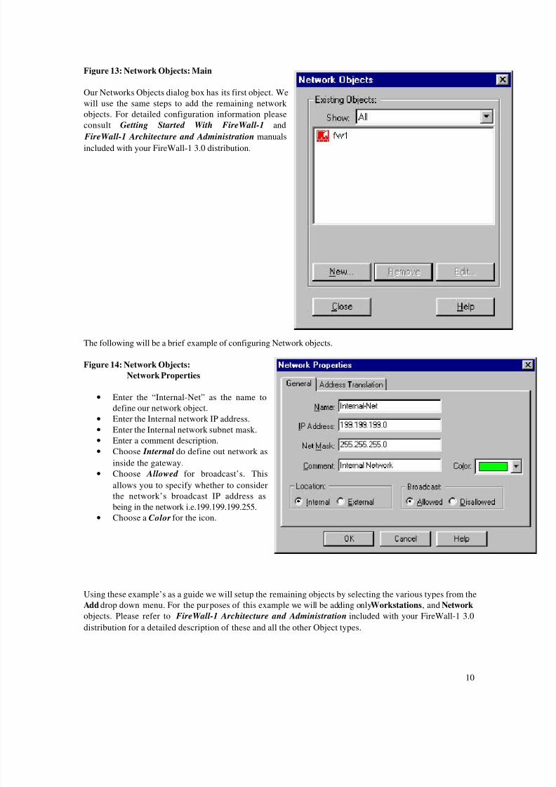
Figure 13: Network Objects: Main
Our Networks Objects dialog box has its first object. We
will use the same steps to add the remaining network
objects. For detailed configuration information please
consult Getting Started With FireWall-1 and
FireWall-1 Architecture and Administration manualsincluded with your FireWall-1 3.0 distribution.
The following will be a brief example of configuring Network objects.
Figure 14: Network Objects:
Network Properties
• Enter the “Internal-Net” as the name to
define our network object.
• Enter the Internal network IP address.
• Enter the Internal network subnet mask.
• Enter a comment description.
• Choose Internal do define out network as
inside the gateway.
• Choose Allowed for broadcast’s. This
allows you to specify whether to consider
the network’s broadcast IP address as
being in the network i.e.199.199.199.255.
• Choose a Color for the icon.
Using these example’s as a guide we will setup the remaining objects by selecting the various types from the
Add drop down menu. For the purposes of this example we will be adding onlyWorkstations, and Network
objects. Please refer to FireWall-1 Architecture and Administration included with your FireWall-1 3.0
distribution for a detailed description of these and all the other Object types.

8/3/2019 Fw Reference 30
http://slidepdf.com/reader/full/fw-reference-30 11/20
11
Using the examples above configure the following Network objects:
NAME TYPE IP Address Mask FireWall-1
fw1 Workstation/Gateway 192.32.32.32 255.255.255.0 Installed/GW
Internal-Net Network 199.199.199.0 255.255.255.0 N/AWWW-Svr Workstat ion/Host 192.32.42.1 255.255.255.0 Not
Installed.
Mail-Svr Workstation/Host 192.32.42.2 255.255.255.0 Not Installed.
FTP-Svr Workstat ion/Host 192.32.42.3 255.255.255.0 Not
Installed.
NOTE: When configuring the Workstation/Host objects remember that they are not gateway’s, nor do they
have FireWall-1 installed on them in this example.
Figure 15: Network Objects: Main
Our completed Network Objects dialog box should look likethis. All of our network objects should be visible in this
window. We can now configure a rule base based on these
objects.

8/3/2019 Fw Reference 30
http://slidepdf.com/reader/full/fw-reference-30 12/20
12
Step-2 : Define User Definitions:
To begin our tasks we will use the User Manager from the main control panel. You access the User ObjectsManager from the Manage drop down menu from the main management window.
Figure 16: Define The User Objects:

8/3/2019 Fw Reference 30
http://slidepdf.com/reader/full/fw-reference-30 13/20
13
Figure 17: Users:
• Select New than Standard User from the Users dialog
box.
• The Show dialog box would allow us to narrow our
view to only groups for example.
• The User Properties dialog box will appear.• We will return to this dialog box to create our group
Managers in which Bill and Joe will be added.
• We could also create a new Template for addition of
multiple common users
Lets Add Our Users:
Figure 18: User: User Properties
• Click the General and add the User
Name “Joe” in this case.
• Enter in a Comment to describe the
user.
• Choose a Color for the icon.
• Enter the users Expiration Date.
For example December 12, 1997
• For user Joe and Bill we will need to
define an authentication method for
their Session Authentication
connections, and set the locations
that they can come from or go to.
Looking at the other options on this dialog box we can configure additional parameters for these users:
• Groups - Add this user to already established groups.
• Authentication - Choose the scheme to authenticate this user.
• Location - Chose the source and destination locations expected from this user.
• Time - Choose specific times that this user’s account will be active.
• Encryption - Define information regarding the user’s SecuRemote Encryption methods.
8/3/2019 Fw Reference 30
http://slidepdf.com/reader/full/fw-reference-30 14/20
14
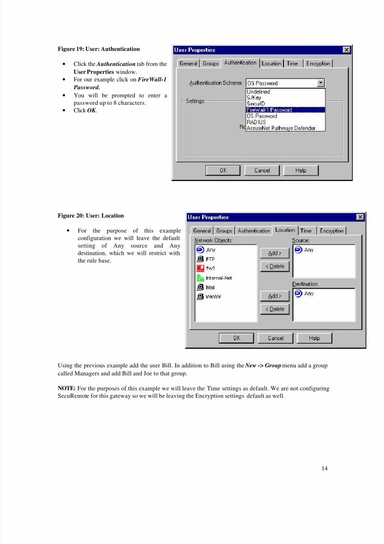
Figure 19: User: Authentication
• Click the Authentication tab from the
User Properties window.
• For our example click on FireWall-1
Password.
• You will be prompted to enter apassword up to 8 characters.
• Click OK .
Figure 20: User: Location
• For the purpose of this example
configuration we will leave the default
setting of Any source and Any
destination, which we will restrict with
the rule base.
Using the previous example add the user Bill. In addition to Bill using the New -> Group menu add a group
called Managers and add Bill and Joe to that group.
NOTE: For the purposes of this example we will leave the Time settings as default. We are not configuring
SecuRemote for this gateway so we will be leaving the Encryption settings default as well.

8/3/2019 Fw Reference 30
http://slidepdf.com/reader/full/fw-reference-30 15/20
15
Figure 21: Users
Our completed User dialog box should look like this:
We have our users Bill and Joe configured for FireWall-1
password authentication, and they both belong to the group
Managers.
Step-3 : Define Rule Base:
From the rule base editor select the Edit drop down menu, select Add Rule, then Bottom to add a new rule
to the Bottom of the policy window:
Figure 22: Security Policy
8/3/2019 Fw Reference 30
http://slidepdf.com/reader/full/fw-reference-30 16/20
16
This action places a generic drop rule to the Bottom of the window. Using the Right Mouse button in each
of the fields (Source - Destination - Service - Action - Track - Install On - Time - and Comment) select Add ,
and modify this rule to achieve our first goal which is allow Internal users to access the Internet and DMZ
unrestricted.
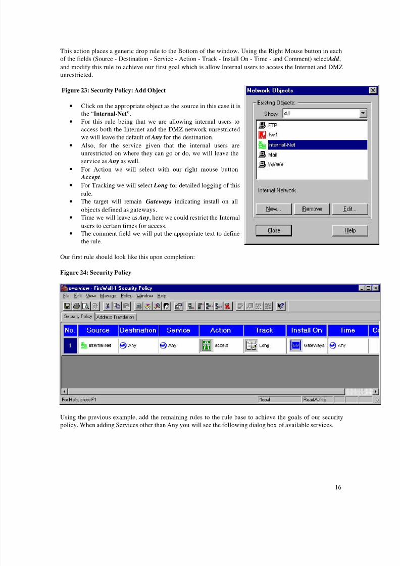
Figure 23: Security Policy: Add Object
• Click on the appropriate object as the source in this case it is
the “Internal-Net”.
• For this rule being that we are allowing internal users to
access both the Internet and the DMZ network unrestricted
we will leave the default of Any for the destination.
• Also, for the service given that the internal users are
unrestricted on where they can go or do, we will leave the
service as Any as well.
• For Action we will select with our right mouse button
Accept.
• For Tracking we will select Long for detailed logging of this
rule.
• The target will remain Gateways indicating install on all
objects defined as gateways.
• Time we will leave as Any, here we could restrict the Internal
users to certain times for access.
• The comment field we will put the appropriate text to define
the rule.
Our first rule should look like this upon completion:
Figure 24: Security Policy
Using the previous example, add the remaining rules to the rule base to achieve the goals of our security
policy. When adding Services other than Any you will see the following dialog box of available services.
8/3/2019 Fw Reference 30
http://slidepdf.com/reader/full/fw-reference-30 17/20
17
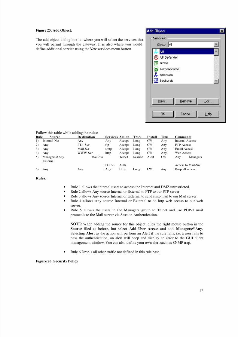
Figure 25: Add Object:
The add object dialog box is where you will select the services that
you will permit through the gateway. It is also where you would
define additional service using the New services menu button.
Follow this table while adding the rules:Rule Source Destination Services Action Track Install Time Commen ts
1) Internal-Net Any Any Accept Long GW Any Internal Access
2) Any FTP-Svr ftp Accept Long GW Any FTP Access
3) Any Mail-Svr smtp Accept Long GW Any Email Access
4) Any WWW-Svr htt p Accept Long GW Any Web Access
5) Managers@Any Mail-Svr Telnet Session Alert GW Any Managers
External
POP-3 Auth Access to Mail-Svr
6) Any Any Any Drop Long GW Any Drop all others
Rules:
• Rule 1 allows the internal users to access the Internet and DMZ unrestricted.
• Rule 2 allows Any source Internal or External to FTP to our FTP server.
• Rule 3 allows Any source Internal or External to send smtp mail to our Mail server.
• Rule 4 allows Any source Internal or External to do http web access to our web
server.
• Rule 5 allows the users in the Managers group to Telnet and use POP-3 mail
protocols to the Mail server via Session Authentication.
NOTE: When adding the source for this object, click the right mouse button in the
Source filed as before, but select Add User Access and add Managers@Any.
Selecting Alert as the action will perform an Alert if the rule fails, i.e. a user fails to
pass the authentication, an alert will beep and display an error to the GUI client
management window. You can also define your own alert such as SNMP trap.
• Rule 6 Drop’s all other traffic not defined in this rule base.
Figure 26: Security Policy

8/3/2019 Fw Reference 30
http://slidepdf.com/reader/full/fw-reference-30 18/20
18
Our completed rule base should look like this:
Step-4 : Install Rule Base:
Figure 27: Install Security Policy Module:
At this point we are ready to install our rule base on the fw1
gateway. From the main GUI window select the Policy drop down
menu and click on Install . You will see a dialog box indicating the
gateways that FireWall-1 is preparing to install to. You should only
see fw1, our gateway. Click OK to install the Policy. The Log
Viewer and System Status windows should indicate the start of a
new Policy.

8/3/2019 Fw Reference 30
http://slidepdf.com/reader/full/fw-reference-30 19/20
19
Step-5 : Install Session Authentication Agent:
Figure 28: Session Authentication Overview:
Figure 29: Session Authentication: Agent Pop-up
In order for nomadic users Joe and Bill to Telnet or
POP-3 to the Mail Server they must first load the
Session Authentication agent on their clients. The
agent is included on the FireWall-1 3.0 CD under the
directory windows/agents. Once the agent is installed
and the user attempts to perform the selected action
he will be prompted to authenticate by the gateway.
First the Authentication agent will challenge the userfor his or her user id so that it can use that information
to determine the users authentication scheme i.e. FW-
1 Password, SKey, SecureID, etc.
InternetNomadic UserIP: 24.24.24.24
FireWall
Mail Server192.32.42.2
Nomadic User: Joe
DMZ
2) FireWall-1 Intercepts
Joe's Packet and verifiesvia the rule base thatSession Authentication isrequired. FW-1 sendsb a c k a S e s s i o nAuthentication ControlPacket which launches theSession AuthenticationAgent on the client.
6) FW-1 receives the User
ID and can now determinethe Users authenticationmethod from the UserDatabase. In this case weused FireWall-1 password.
4) User Joe Prompted ForUser ID.
8) User Joe Prompted ForPassword.
Session Authentication Process
3) FW-1 sends Session Auth. Control Packet To Agent
5) Client Joe Enters His User ID. It is sent back to FW-1.
1) Client Joe Telnet's to the Mail Server.
7) FW-1 sends Password Request To Session Agent
9) Client Joe Enters Password. It is sent back to FW-1.
10) Authentication Passed - Telnet Connection Established

8/3/2019 Fw Reference 30
http://slidepdf.com/reader/full/fw-reference-30 20/20
Figure 30: Session Authentication: Agent Pop-up
After the user ID is verified by the FireWall, the user
is challenged for his or here password based upon theuser authentication scheme defined in the user
database on the FireWall-1 management server.
If the password matches the user’s authentication
scheme, authentication is granted and the Telnet
session is permitted to pass through the FireWall.
This concludes our quick-setup. Please consult the FireWall-1 3.0 documentation for more detailed
information regarding FireWall-1 3.0 configuration options and features.
![FW: [Fwd: FW: Beautiful_TIBET]](https://static.fdocuments.in/doc/165x107/54b8dcf94a79592d6a8b4612/fw-fwd-fw-beautifultibet.jpg)


![Fw 190 D-9 · 2020. 12. 30. · DCS [Fw 190 D-9] 2 INTRODUCTION Dear User, Thank you for your purchase of DCS: Fw 190 D-9, a simulation of the legendary German World War II fighter,](https://static.fdocuments.in/doc/165x107/61047c1d6046b4467a6b93a6/fw-190-d-9-2020-12-30-dcs-fw-190-d-9-2-introduction-dear-user-thank-you.jpg)


![thriftynorthwestmom.com · 2018-06-10 · .lunodqg6ljqdwxuh3uhplxp'ulqnlqj:dwhu r] fw hd .lunodqg6ljqdwxuh3uhplxp'ulqnlqj:dwhu owu erwwohv fw hd 3huulhu6sdunolqj0lqhudo:dwhu fw hd](https://static.fdocuments.in/doc/165x107/5f6d829cc2050f4ba47bcca9/2018-06-10-lunodqg6ljqdwxuh3uhplxpulqnlqjdwhu-r-fw-hd-lunodqg6ljqdwxuh3uhplxpulqnlqjdwhu.jpg)