Fuzzy Pid With Gimbal
8
Internation al Journal of Compute r Applications (0975 – 8887) Volume 77 – No.3, September 2013 6 Fuzzy Stabilization Loop of One Axis Gimbal System Maher Abdo Department of Electrical Engineering MUT, Tehran Ahmad Reza Vali Department of Electrical Engineering MUT, Tehran Ali Reza Toloei Department of Aerospace science SBU, tehran ABSTRACT The application of inertial stabilization system is to stabilize the sensor’s line of sight toward a target by isolating the sensor from the disturbances induced by the operating environment. The purpose of this paper is to present a model of control servo system for one axis gimbal mechanism using fuzzy PID type controller. The gimbals torque relationships are derived using Newton’s law considering the base angular motion and dynamic unbalance. Then, the stabilization loop is constructed and the proposed fuzzy controller is designed. The overall control system is simulated using MATLAB/Simulink, then the system performance is investigated in different cases for both conventional PI and fuzzy PID controller. A comparison study is made based on some performance criteria. The results obtained in different conditions confirms that a further improved system performance can be achieved using the proposed fuzzy controller as compared to the conventional PI controller. The simulation results proves the efficiency of the proposed fuzzy controller which offers a better response than PI one, and improves further the transient and the steady-state performance. General Terms Inertial stabilization systems, fuzzy control, servo systems Keywords Gimbal System, Rate Gyro, Line of Sight, Stabilization Loop 1. INTRODUCTION The optical equipments (such as IR, radar, laser, and television) have found a wide use in many important applications, for example image processing, guided missiles, tracking systems, and navigation systems. In such systems, the optical sensor axis must be accurately pointed from a movable base to a fixed or moving target. Therefore, the sensor’s line of sight (LOS) must be strictly controlled. In such an environment where the equipment is typically mounted on a movable platform, maintaining sensor orientation toward a target is a serious challenge. An Inertial Stabilization Platform (ISP) is an appropriate way that can solve this challenge [1]. These systems can provide stabilization to the sensor while different disturbances affect it. The most important disturbance sources are the base angular motion, the dynamics of gimbaled system, and the gimbal mass unbalance. (ISPs) are usually constructed as an assembly of structure, bearings, and motors called a gimbal to which a gyroscope is placed [2]. It has been shown earlier that the jitter on the LOS can be reduced by mounting the electro optical EO payload on a set of gimbals. Gimbals are precision electro-mechanical combinations which are mainly used to isolate the optical equipment from the disturbance caused by the operating environment, such as various disturbance torques and body motion [3]. Such systems are usually required to maintain stable operation and guarantee accurate pointing and tracking for the target even when there are changes in the system dynamics and operational conditions. The mathematical model and the control system of gimbal systems have been studied in many researches. Concerning the mathematical model, several derivations have been proposed using different assumptions. In [4], the kinematics and geometrical coupling relationships for two degree of freedom gimbal assembly have been obtained for a simplified case when each gimbal is balanced and the gimbaled elements bodies are suspended about principal axes. The equations of motion for the two axes gimbal configuration have been presented in [5] based on the assumption that the gimbals are rigid bodies and have no mass unbalance. Both researches [4, 5] mentioned above have not been simulated. A single degree of freedom (SDOF) gimbal operating in a complex vibration environment has been presented by Daniel in [6]. It has been illustrated how the vibrations excite both static and dynamic unbalance disturbance torques, which can be eliminated by statically and dynamically balancing the gimbal, which is regarded costly and time consuming [6]. In [7], the motion equations have been derived on the assumption that gimbals have no dynamic mass unbalance, and the mass distribution of gimbals is symmetrical with respect to the frame axes considered. In addition, the effects of base angular velocities were not highlighted. In [8], a two axes gimbal mechanism was introduced and just the modeling of azimuth axis was focused, and the elevation angle was kept fixed and cross moments of inertia were taken to be zero. In both [5] and [9], the dynamical model of elevation and azimuth gimbals have been derived on the assumption that gimbals mass distribution is symmetrical with respect to the gimbals frame axes. Therefore, the products of inertia were neglected, and the model was simplified. On the other hand, the control system of gimbal configurations has been constructed using different control approaches. In [7], a proxy-based sliding mode has been applied on two axes gimbal system. Also, [10] proposed the sliding mode control under the assumption of uncoupled identical elevation and azimuth channels. In [11], modern synthesis tools such as linear quadratic regulator (LQR) or linear quadratic Gaussian with loop transfer recovery (LQG/LTR) control for a wideband controller have also been used in the line of sight stabilization for mobile land vehicle. Also, [12] presented a linear quadratic Gaussian (LQG) algorithm for estimating and compensating in real time a particular class o f disturbances. Besides con ventional control methods mentioned above, some advance control techniques, such as fuzzy logical control (FLC) [13], robust control [14], variable structure control (VSC) [15], were also applied in LOS inertia stabilization systems during recent years. In [15],
-
Upload
ahmed-alostaz -
Category
Documents
-
view
243 -
download
0
Transcript of Fuzzy Pid With Gimbal
8/14/2019 Fuzzy Pid With Gimbal
http://slidepdf.com/reader/full/fuzzy-pid-with-gimbal 1/8
International Journal of Computer Applications (0975 – 8887)
Volume 77 – No.3, September 2013
6
Fuzzy Stabilization Loop of One Axis Gimbal System
Maher AbdoDepartment of Electrical
EngineeringMUT, Tehran
Ahmad Reza ValiDepartment of Electrical
EngineeringMUT, Tehran
Ali Reza ToloeiDepartment of Aerospace
scienceSBU, tehran
ABSTRACT The application of inertial stabilization system is to stabilizethe sensor’s line of sight toward a target by isolating thesensor from the disturbances induced by the operatingenvironment. The purpose of this paper is to present a modelof control servo system for one axis gimbal mechanism using
fuzzy PID type controller. The gimbals torque relationshipsare derived using Newton’s law considering the base angularmotion and dynamic unbalance. Then, the stabilization loop isconstructed and the proposed fuzzy controller is designed.The overall control system is simulated usingMATLAB/Simulink, then the system performance isinvestigated in different cases for both conventional PI andfuzzy PID controller. A comparison study is made based onsome performance criteria. The results obtained in differentconditions confirms that a further improved system performance can be achieved using the proposed fuzzycontroller as compared to the conventional PI controller. Thesimulation results proves the efficiency of the proposed fuzzycontroller which offers a better response than PI one, andimproves further the transient and the steady-state performance.
General Terms Inertial stabilization systems, fuzzy control, servo systems
Keywords Gimbal System, Rate Gyro, Line of Sight, Stabilization Loop
1. INTRODUCTIONThe optical equipments (such as IR, radar, laser, andtelevision) have found a wide use in many importantapplications, for example image processing, guided missiles,tracking systems, and navigation systems. In such systems,the optical sensor axis must be accurately pointed from a
movable base to a fixed or moving target. Therefore, thesensor’s line of sight (LOS) must be strictly controlled. Insuch an environment where the equipment is typicallymounted on a movable platform, maintaining sensororientation toward a target is a serious challenge. An InertialStabilization Platform (ISP) is an appropriate way that cansolve this challenge [1]. These systems can providestabilization to the sensor while different disturbances affectit. The most important disturbance sources are the baseangular motion, the dynamics of gimbaled system, and thegimbal mass unbalance. (ISPs) are usually constructed as anassembly of structure, bearings, and motors called a gimbal towhich a gyroscope is placed [2]. It has been shown earlier thatthe jitter on the LOS can be reduced by mounting the electrooptical EO payload on a set of gimbals. Gimbals are precisionelectro-mechanical combinations which are mainly used toisolate the optical equipment from the disturbance caused by
the operating environment, such as various disturbancetorques and body motion [3]. Such systems are usuallyrequired to maintain stable operation and guarantee accurate pointing and tracking for the target even when there arechanges in the system dynamics and operational conditions.The mathematical model and the control system of gimbalsystems have been studied in many researches. Concerningthe mathematical model, several derivations have been proposed using different assumptions. In [4], the kinematicsand geometrical coupling relationships for two degree offreedom gimbal assembly have been obtained for a simplifiedcase when each gimbal is balanced and the gimbaled elements bodies are suspended about principal axes. The equations ofmotion for the two axes gimbal configuration have been presented in [5] based on the assumption that the gimbals arerigid bodies and have no mass unbalance. Both researches [4,5] mentioned above have not been simulated. A single degreeof freedom (SDOF) gimbal operating in a complex vibrationenvironment has been presented by Daniel in [6]. It has beenillustrated how the vibrations excite both static and dynamicunbalance disturbance torques, which can be eliminated by
statically and dynamically balancing the gimbal, which isregarded costly and time consuming [6]. In [7], the motionequations have been derived on the assumption that gimbalshave no dynamic mass unbalance, and the mass distribution ofgimbals is symmetrical with respect to the frame axesconsidered. In addition, the effects of base angular velocitieswere not highlighted. In [8], a two axes gimbal mechanismwas introduced and just the modeling of azimuth axis wasfocused, and the elevation angle was kept fixed and crossmoments of inertia were taken to be zero. In both [5] and [9],the dynamical model of elevation and azimuth gimbals have been derived on the assumption that gimbals mass distributionis symmetrical with respect to the gimbals frame axes.Therefore, the products of inertia were neglected, and the
model was simplified. On the other hand, the control systemof gimbal configurations has been constructed using differentcontrol approaches. In [7], a proxy-based sliding mode has been applied on two axes gimbal system. Also, [10] proposedthe sliding mode control under the assumption of uncoupledidentical elevation and azimuth channels. In [11], modernsynthesis tools such as linear quadratic regulator (LQR) orlinear quadratic Gaussian with loop transfer recovery(LQG/LTR) control for a wideband controller have also beenused in the line of sight stabilization for mobile land vehicle.Also, [12] presented a linear quadratic Gaussian (LQG)algorithm for estimating and compensating in real time a particular class of disturbances. Besides conventional controlmethods mentioned above, some advance control techniques,such as fuzzy logical control (FLC) [13], robust control [14],
variable structure control (VSC) [15], were also applied inLOS inertia stabilization systems during recent years. In [15],
8/14/2019 Fuzzy Pid With Gimbal
http://slidepdf.com/reader/full/fuzzy-pid-with-gimbal 2/8
International Journal of Computer Applications (0975 – 8887)
Volume 77 – No.3, September 2013
7
a variable structure-augmented adaptive controller for a gyro-mirror line of sight stabilization platform has been developed.The H∞ control methodology was used in [16] to design ahigh performance controller so as to control the rate of theline of sight. [17] Introduced an efficient full-matrix fuzzylogic controller for a gyro mirror line-of-sight stabilization platform. However, a majority of these algorithms were
complex and difficult to be realized. In recent years, the fuzzycontrol technology has been developed successfully. Itimproves the system control performance, and has the goodadaptability for the system with nonlinear mathematicalmodel and uncertain factors [18]. It can be realized that theimportance of gimbal systems gave rise to be investigated in alot of papers as mentioned above. Without doubt, theseresearches have contributed in studying and explaining gimbalsystems, but the model of such systems is still difficult andcomplicated to be understood by engineers because the vastmajority of these researches have interested in the two ormulti axes gimbal systems as well as these systems have beeninvestigated considering the inertia cross coupling betweenaxes. Therefore, this paper is devoted for twofold purpose.
First, to present the model of one axis gimbal system in orderto simplify the picture of the gimbal systems and to furtherinvestigate the properties of this configuration. In anotherwords, this paper forms a primary theoretical base fordesigning a multi axes gimbal systems. Second aim is tointroduce a self-tuning PID-type fuzzy technique for one axisgimbal system. The paper is organized in the followingmanner. The problem is formulated and the equation ofgimbal motion is derived in section 2 and 3 respectively.Afterwards, the stabilization loop is investigated andconstructed in section 4. Then, in section 5 the proposed fuzzycontroller is designed. The simulation results are introduced insection 6. Finally, the conclusion remarks are highlighted insection 7.
2. PROBLEM FORMULATIONRegarding the rotational motion, Newton’s first law states thata torque must be applied on the body to make it acceleratingwith respect to an inertial frame. Moreover, utilizing Newton’s second law, it can be established that if a net torqueT is applied to a homogenous rigid mass having a moment ofinertia J, then the body develops an angular acceleration α [2]according to
.T J (1)
Therefore, it can be concluded that to prevent an object fromrotating with respect to inertial space, the applied torque must be zero. However, even in a carful electromechanical design,multiple torque disturbances sources can affect on a real
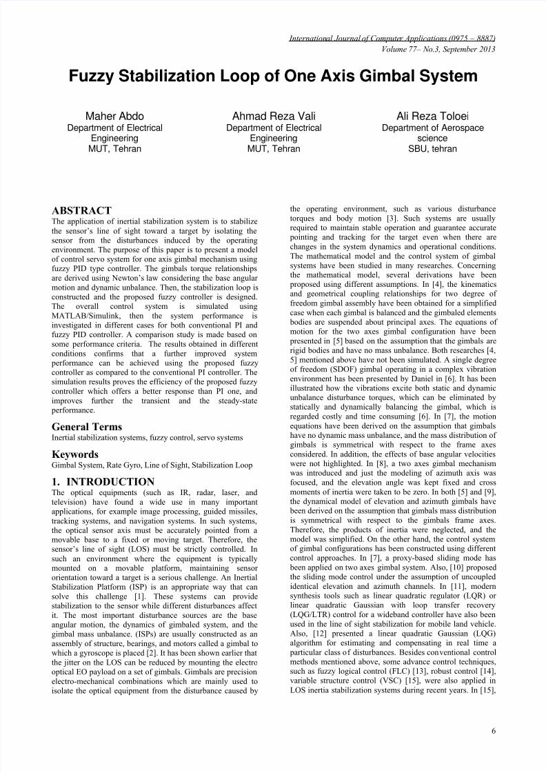
mechanism causing excessive motion or jitter of (LOS). Also,a means is required to control the object so that it canaccurately respond to command inputs. Therefore, rate ordisplacement gyros are typically attached to the object tomeasure the inertial rotation about the axes that requirestabilization and control. The gyro is used in a closed-loopservo system to counteract the disturbances and at the sametime, allow the object to be controlled from external commandinputs [2]. The single-axis stabilized gimbal is shown inFigure 1. It is clear that the purpose of the gimbal is to isolatethe stabilized object from base rotation, and allow (LOS) to be pointed. The block diagram in Figure 2 shows the gimbalstabilization system. It is typically configured as a rate servo.That is, the system attempts to null the difference between the
rate command input c and the angular rate of the gimbal Ae
.
(
A
)platform
r
d
ei
j
k
Ae
Fig 1: A single-axis gimbal mechanism.
When the rate command input is zero or absent, the systemattempts to null the total torque applied to the gimbal, whichrequires that the stabilization closed-loop generates a controltorque at the motor that is equal and opposite to the netdisturbance torque.
c Rate
command
Gyro rate feedback LOS rate
Totaltorque
Rate error
1
JsController DC motor
Inertia
Rate gyro
Ae
DT
mT T E
Motortorque
Torquedisturbance
Fig 2: LOS stabilized servo control loop.
From Figure 2, it can be seen that
1 Ae
Ae AeT J s J J T J s
(2)
The control loop introduced works as stabilization system
when the rate command inputc
is zero, which means that
the control system output Ae
must be zero. While this
system tries to track the nonzero rate command input. As aresult, the problem can be formulated as follows. The servocontrol in general can be broken into two fundamental classes.The first class deals with command tracking. It addresses thequestion of how well does the actual motion follow what is being commanded. The second general class of servo controladdresses the disturbance rejection characteristics of the
system. Disturbances can be anything from torquedisturbances on the motor shaft to incorrect motor parameterestimations used in the feed forward control.
3. MATHEMATICAL MODEL OF
GIMBAL MOTIONIn this research, two reference frames are interested as shownin Figure 1. Frame P fixed to the fuselage body (base) withaxes , ,i j k , and frame A fixed to the gimbal (stabilized
object) with axes , ,r e d where r-axis coincides with the
sensor optical axis. The center of rotation is at the origin ofthe two frames. A transformation between frame P and A ismade in terms of positive angle ε (gimbal angle) about the e -axis.
8/14/2019 Fuzzy Pid With Gimbal
http://slidepdf.com/reader/full/fuzzy-pid-with-gimbal 3/8
International Journal of Computer Applications (0975 – 8887)
Volume 77 – No.3, September 2013
8
cos 0 sin
0 1 0
sin 0 cos
A
P C
(3)
The inertial angular velocity vectors of frames P and A,respectively are
,
pi Ar
p A
P I pj A I Ae
Ad pk
(4)
Where , ,i j k p p p are the base angular velocities of frame
P in relation to inertial space about i, j, and k axes
respectively, and , ,r e d A A A are the gimbal angular
velocities in relation to inertial space about the r, e, and d axesrespectively. The inertia matrix of the gimbal is
r re rd
A
re e de
rd de d
A A A
J A A A
A A A
(5)
Where , ,r e d
A A A are gimbal moments of inertia about r, e,
and d axes, , ,re rd de
A A A are gimbal moments products of
inertia. The angular velocitiese A is the output of the
stabilization loop (servo control system), the purpose of which
is to make it possible to keep 0e A despite disturbances,
and by that keep the sensor nonrotating in inertial space [5].
e A can be measured by a rate gyro placed on the gimbal.
Utilizing (3), the angular velocities of the stabilized object are
cos sin ( )
( )sin cos ( )
Ar Pi Pk
Ae Pj
Ad Pi Pk
a
bc
(6)
In [5], by Newton’s second law, the external kinematictorques applied to the body A can be written as follows
A A A
A I
d T H H
dt (7)
Where A H is the angular momentum given by
. A A A
A I H J (8)
r Ar re Ae rd Ad r
A
re Ar e Ae de Ad e
rd Ar de Ae d Ad d
A A A H
H A A A H
A A A H
(9)
The moment equation for a rotating frame is
r Ae d Ad e
e Ad r Ar d
d Ar e Ae r
H H H
T H H H
H H H
(10)
The torque provided by the DC motor and applied about thegimbal e-axis is the e-component of matrix (10).
m e Ad r Ar d T H H H (11)
This equation can be obtained as a differential equation for the base angular velocity in the following form
2 2( ) ( )
( ) ( )
e Ae m d r Ar Ad rd Ar Ad
de Ad Ae Ar re Ar Ae Ad
A T A A A
A A
(12)
mT represents the sum of the motor torque and external
imperfection disturbance torques. From stabilization point of
view, the "inertia terms" on the right represent unwanteddisturbances. They will enter the control system in the same point as an external torque; consequently, they can be
regarded as torque disturbance DT (Figure 2).2 2( ) ( )
( ) ( )
D d r Ar Ad rd Ar Ad
de Ad Ae Ar re Ar Ae Ad
T A A A
A A
(13)
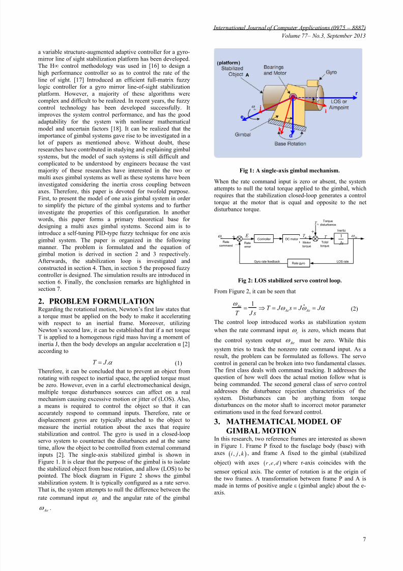
From the control point of view, it is suitable to let mT
represent only the motor torque. Therefore, the equation (12)can be represented by the block diagram in Figure 3. It is clearthat the motor torque and the disturbance torques are inputs to
an integrator which includes the moment of inertiae
A , and
the output is the angular velocity Ae
.
DT
mT 1
e A s
Ae
Fig 3: Gimbal motion equation.
Equation 13 shows that the torque disturbance is caused bythe base angular motion and the gimbal inertia parameters.Therefore, when the base is nonrotating
0 Pi Pj Pk the disturbance term is zero and just
the motor torque mT affects on the platform (stabilized object
A). With regard to inertia parameters, it must be mentionedthat the dynamic mass unbalance is the result of a non-symmetrical mass distribution called Product of Inertia (POI)[6]. The dynamic unbalance concept can be indicated by theinertia matrix. Therefore, if the considered gimbal has asymmetrical mass distribution with respect to its frame axes,
then the gimbal has no dynamic unbalance and its inertiamatrix is diagonal. Also, if the gimbal has a non-symmetricalmass distribution with respect to its frame axes, then thegimbal has dynamic unbalance and its inertia matrix is notdiagonal. Actually, in most papers, the model of gimbalsystem has been simplified using certain choices of inertia parameters to reduce the effects of dynamic mass unbalancewhich is considered an inevitable imperfection that can beencountered even in a well designed system. For example, in[4, 5], it has been assumed that the gimbal has no dynamicunbalance i.e., 0re rd de A A A . When this assumption is
applied on the gimbal model indicated in (12), the equation ofgimbal motion will be simplified to
( )e Ae m d r Ar Ad A T A A . In this paper, it is assumed that
the gimbal has dynamic mass unbalance, so the modelindicated in equation (12) will be interested.
4. STABILIZATION LOOP
CONSTRUCTIONIt can be seen from Figure 2 that the stabilization loop isconstituted of controller, DC motor, platform, and rate gyro.These components are identified as follows. Although, theresearchers tried to utilize and apply many different moderntechniques to control inertia stabilization systems, theconventional PID and its constructors are still the most usedapproach due to their simple structure, cheap costs, simpledesign and high performance [19]. Therefore, In order toevaluate the efficiency of proposed fuzzy controller, PI
controller (equation 14) has been utilized to be compared laterwith the performance of the proposed fuzzy controller.
8/14/2019 Fuzzy Pid With Gimbal
http://slidepdf.com/reader/full/fuzzy-pid-with-gimbal 4/8
International Journal of Computer Applications (0975 – 8887)
Volume 77 – No.3, September 2013
9
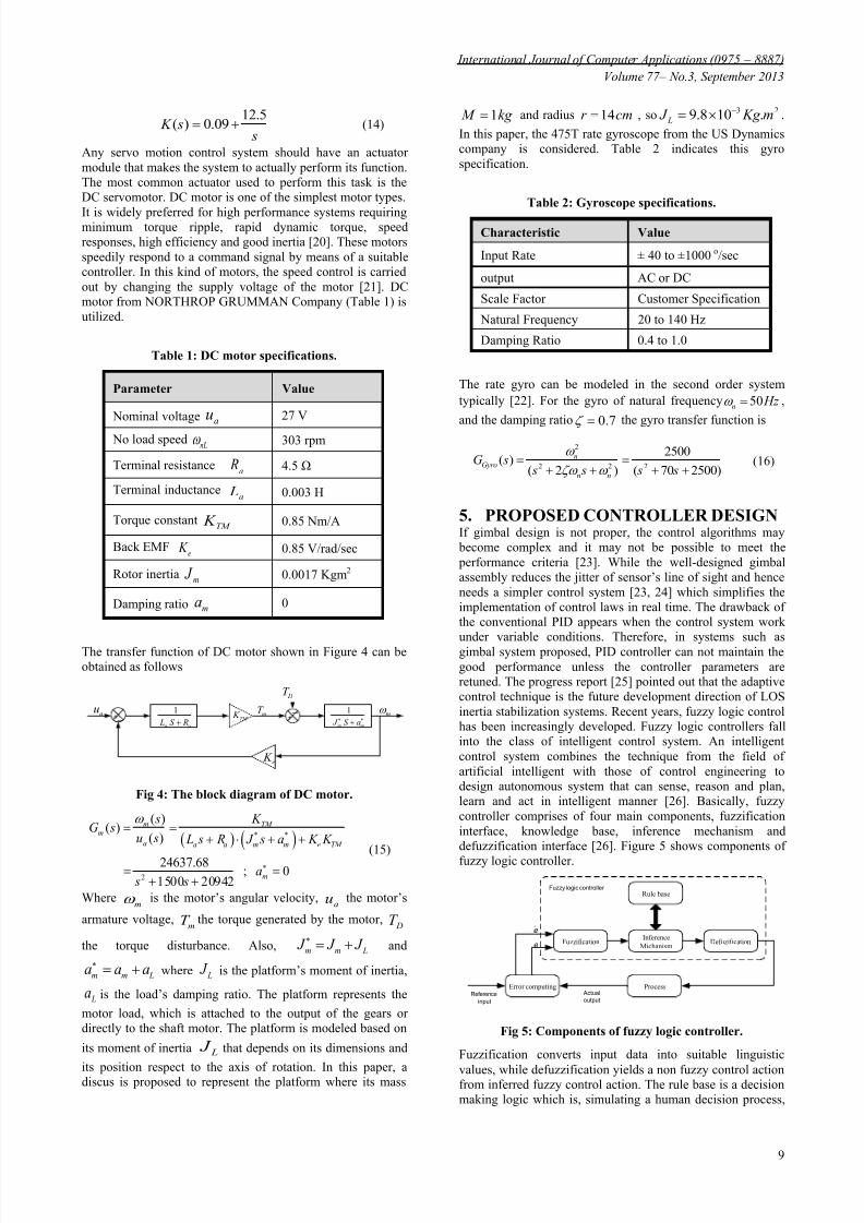
12.5( ) 0.09 K s
s (14)
Any servo motion control system should have an actuatormodule that makes the system to actually perform its function.The most common actuator used to perform this task is theDC servomotor. DC motor is one of the simplest motor types.
It is widely preferred for high performance systems requiringminimum torque ripple, rapid dynamic torque, speedresponses, high efficiency and good inertia [20]. These motorsspeedily respond to a command signal by means of a suitablecontroller. In this kind of motors, the speed control is carriedout by changing the supply voltage of the motor [21]. DCmotor from NORTHROP GRUMMAN Company (Table 1) isutilized.
Table 1: DC motor specifications.
Parameter Value
Nominal voltage au 27 V
No load speednL
303 rpm
Terminal resistancea
R 4.5 Ω
Terminal inductancea L 0.003 H
Torque constantTM K 0.85 Nm/A
Back EMFe K 0.85 V/rad/sec
Rotor inertiam J 0.0017 Kgm2
Damping ratio ma 0
The transfer function of DC motor shown in Figure 4 can beobtained as follows
1
a a L S R
1
m m J S a TM
K
e K
au
DT
mT m
Fig 4: The block diagram of DC motor.
* *
2
( )( )
( )
24637.68; 0
1500 20942
m TM m
a a a m m e TM
m
s K G s
u s L s R J s a K K
a s s
(15)
Wherem is the motor’s angular velocity,
au the motor’s
armature voltage,mT the torque generated by the motor,
DT
the torque disturbance. Also, m m L J J J
and
m m La a a where L J is the platform’s moment of inertia,
La is the load’s damping ratio. The platform represents the
motor load, which is attached to the output of the gears ordirectly to the shaft motor. The platform is modeled based on
its moment of inertia L
J that depends on its dimensions and
its position respect to the axis of rotation. In this paper, adiscus is proposed to represent the platform where its mass
1 M kg and radius 14r cm , so 3 29.8 10 . L J Kg m .
In this paper, the 475T rate gyroscope from the US Dynamicscompany is considered. Table 2 indicates this gyrospecification.
Table 2: Gyroscope specifications.
Characteristic Value
Input Rate ± 40 to ±1000 o/sec
output AC or DC
Scale Factor Customer Specification
Natural Frequency 20 to 140 Hz
Damping Ratio 0.4 to 1.0
The rate gyro can be modeled in the second order systemtypically [22]. For the gyro of natural frequency 50
n Hz ,
and the damping ratio 0.7 the gyro transfer function is
2
2 2 2
2500( )
( 2 ) ( 70 2500)
nGyro
n n
G s s s s s
(16)
5. PROPOSED CONTROLLER DESIGNIf gimbal design is not proper, the control algorithms may become complex and it may not be possible to meet the performance criteria [23]. While the well-designed gimbalassembly reduces the jitter of sensor’s line of sight and henceneeds a simpler control system [23, 24] which simplifies theimplementation of control laws in real time. The drawback ofthe conventional PID appears when the control system work
under variable conditions. Therefore, in systems such asgimbal system proposed, PID controller can not maintain thegood performance unless the controller parameters areretuned. The progress report [25] pointed out that the adaptivecontrol technique is the future development direction of LOSinertia stabilization systems. Recent years, fuzzy logic controlhas been increasingly developed. Fuzzy logic controllers fallinto the class of intelligent control system. An intelligentcontrol system combines the technique from the field ofartificial intelligent with those of control engineering todesign autonomous system that can sense, reason and plan,learn and act in intelligent manner [26]. Basically, fuzzycontroller comprises of four main components, fuzzificationinterface, knowledge base, inference mechanism anddefuzzification interface [26]. Figure 5 shows components of
fuzzy logic controller.
Fuzzification Defuzification
Rule base
Inference
Michanism
ProcessError computingReference
input
Actual
output
Fuzzy logic controller
e
e
Fig 5: Components of fuzzy logic controller.
Fuzzification converts input data into suitable linguistic
values, while defuzzification yields a non fuzzy control actionfrom inferred fuzzy control action. The rule base is a decisionmaking logic which is, simulating a human decision process,
8/14/2019 Fuzzy Pid With Gimbal
http://slidepdf.com/reader/full/fuzzy-pid-with-gimbal 5/8
International Journal of Computer Applications (0975 – 8887)
Volume 77 – No.3, September 2013
10
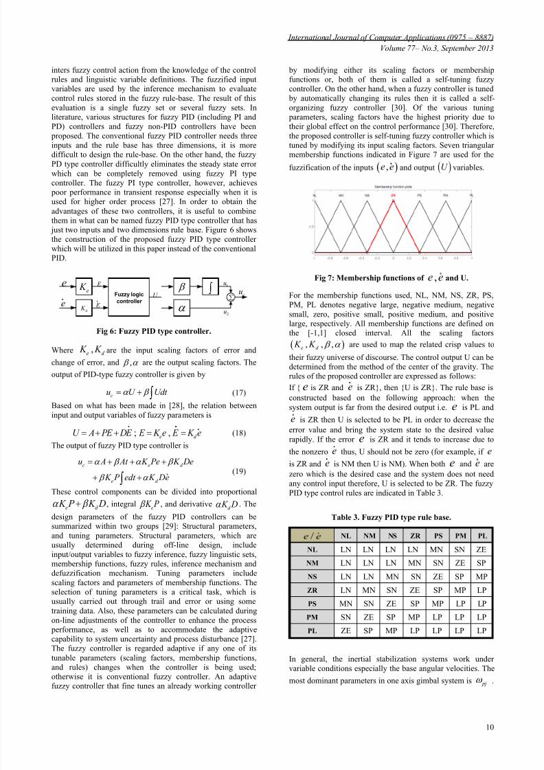
inters fuzzy control action from the knowledge of the controlrules and linguistic variable definitions. The fuzzified inputvariables are used by the inference mechanism to evaluatecontrol rules stored in the fuzzy rule-base. The result of thisevaluation is a single fuzzy set or several fuzzy sets. Inliterature, various structures for fuzzy PID (including PI andPD) controllers and fuzzy non-PID controllers have been
proposed. The conventional fuzzy PID controller needs threeinputs and the rule base has three dimensions, it is moredifficult to design the rule-base. On the other hand, the fuzzyPD type controller difficultly eliminates the steady state errorwhich can be completely removed using fuzzy PI typecontroller. The fuzzy PI type controller, however, achieves poor performance in transient response especially when it isused for higher order process [27]. In order to obtain theadvantages of these two controllers, it is useful to combinethem in what can be named fuzzy PID type controller that has just two inputs and two dimensions rule base. Figure 6 showsthe construction of the proposed fuzzy PID type controllerwhich will be utilized in this paper instead of the conventionalPID.
Fuzzy logic
controller
e
e
e K
d K
E
E
U
1u
2u
cu
Fig 6: Fuzzy PID type controller.
Where ,e d
K K are the input scaling factors of error and
change of error, and , are the output scaling factors. The
output of PID-type fuzzy controller is given by
cu U Udt (17)
Based on what has been made in [28], the relation betweeninput and output variables of fuzzy parameters is
; ,e d
U A PE DE E K e E K e (18)
The output of fuzzy PID type controller is
c e d
e d
u A At K Pe K De
K P edt K De
(19)
These control components can be divided into proportional
e d K P K D , integral
e K P , and derivative
d K D . The
design parameters of the fuzzy PID controllers can besummarized within two groups [29]: Structural parameters,
and tuning parameters. Structural parameters, which areusually determined during off-line design, includeinput/output variables to fuzzy inference, fuzzy linguistic sets,membership functions, fuzzy rules, inference mechanism anddefuzzification mechanism. Tuning parameters includescaling factors and parameters of membership functions. Theselection of tuning parameters is a critical task, which isusually carried out through trail and error or using sometraining data. Also, these parameters can be calculated duringon-line adjustments of the controller to enhance the process performance, as well as to accommodate the adaptivecapability to system uncertainty and process disturbance [27].The fuzzy controller is regarded adaptive if any one of itstunable parameters (scaling factors, membership functions,and rules) changes when the controller is being used;
otherwise it is conventional fuzzy controller. An adaptivefuzzy controller that fine tunes an already working controller
by modifying either its scaling factors or membershipfunctions or, both of them is called a self-tuning fuzzycontroller. On the other hand, when a fuzzy controller is tuned by automatically changing its rules then it is called a self-organizing fuzzy controller [30]. Of the various tuning parameters, scaling factors have the highest priority due totheir global effect on the control performance [30]. Therefore,
the proposed controller is self-tuning fuzzy controller which istuned by modifying its input scaling factors. Seven triangularmembership functions indicated in Figure 7 are used for the
fuzzification of the inputs ,e e and output U variables.
Fig 7: Membership functions of ,e e and U.
For the membership functions used, NL, NM, NS, ZR, PS,PM, PL denotes negative large, negative medium, negativesmall, zero, positive small, positive medium, and positivelarge, respectively. All membership functions are defined onthe [-1,1] closed interval. All the scaling factors
, , ,e d K K are used to map the related crisp values to
their fuzzy universe of discourse. The control output U can bedetermined from the method of the center of the gravity. Therules of the proposed controller are expressed as follows:
If { e is ZR and e is ZR}, then {U is ZR}. The rule base isconstructed based on the following approach: when the
system output is far from the desired output i.e. e is PL ande is ZR then U is selected to be PL in order to decrease theerror value and bring the system state to the desired valuerapidly. If the error e is ZR and it tends to increase due to
the nonzero e thus, U should not be zero (for example, if e
is ZR and e is NM then U is NM). When both e and e arezero which is the desired case and the system does not needany control input therefore, U is selected to be ZR. The fuzzyPID type control rules are indicated in Table 3.
Table 3. Fuzzy PID type rule base.
/e e NL NM NS ZR PS PM PL
NL LN LN LN LN MN SN ZE
NM LN LN LN MN SN ZE SP
NS LN LN MN SN ZE SP MP
ZR LN MN SN ZE SP MP LP
PS MN SN ZE SP MP LP LP
PM SN ZE SP MP LP LP LP
PL ZE SP MP LP LP LP LP
In general, the inertial stabilization systems work undervariable conditions especially the base angular velocities. The
most dominant parameters in one axis gimbal system is pj .
8/14/2019 Fuzzy Pid With Gimbal
http://slidepdf.com/reader/full/fuzzy-pid-with-gimbal 6/8
8/14/2019 Fuzzy Pid With Gimbal
http://slidepdf.com/reader/full/fuzzy-pid-with-gimbal 7/8
International Journal of Computer Applications (0975 – 8887)
Volume 77 – No.3, September 2013
12
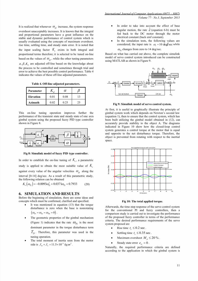
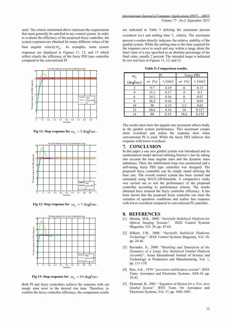
used. The criteria mentioned above represent the requirementsthat must generally be satisfied in any control system. In orderto evaluate the efficiency of the proposed fuzzy controller, thesystem responses are obtained for many different values of the
base angular velocity pj . As examples, some system
responses are displayed in Figures 11, 12, and 13 which
reflect clearly the efficiency of the fuzzy PID type controllercompared to the conventional PI.
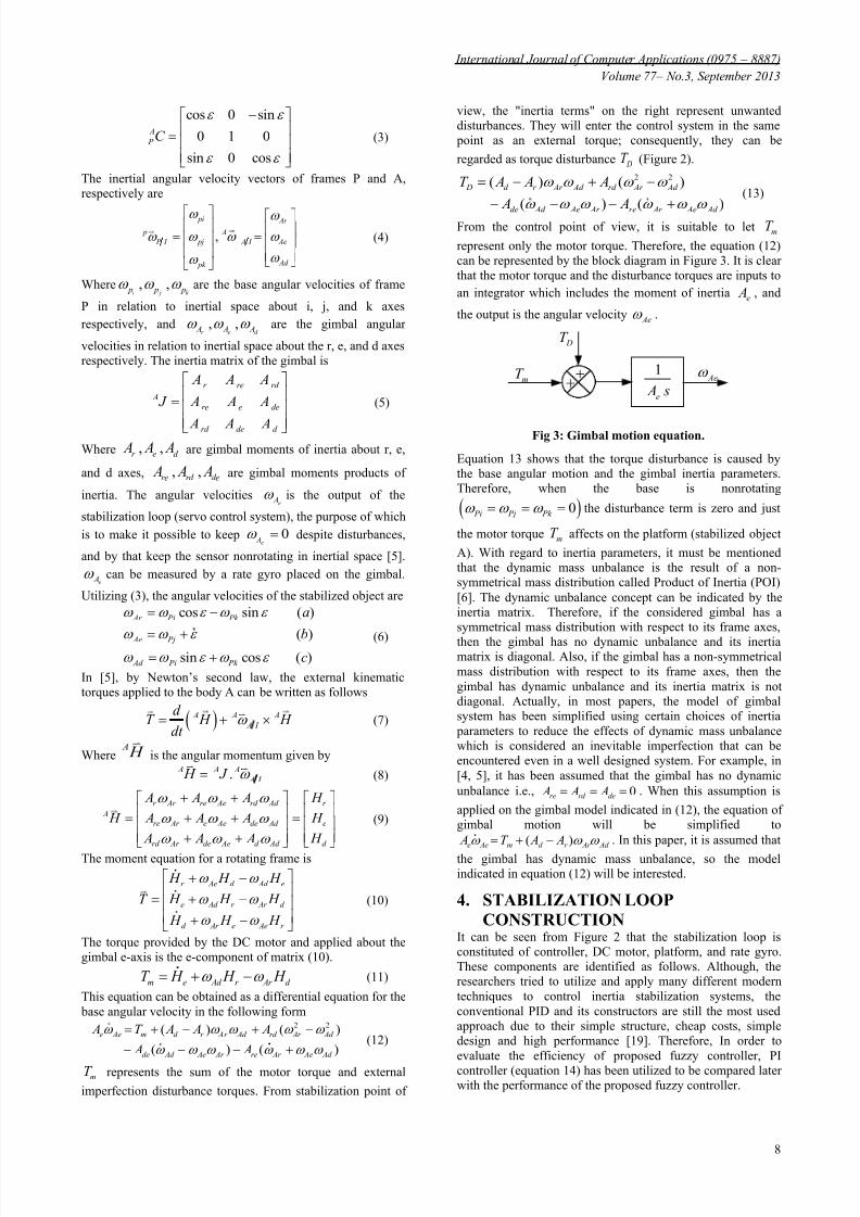
Fig 11: Step response for 3 deg sec Pj .
Fig 12: Step response for 7 deg sec Pj .
Fig 13: Step response for 10 deg sec Pj .
Both PI and fuzzy controllers achieve the response with outsteady state error in the desired rise time. Therefore, toconfirm the fuzzy controller efficiency, the comparison results
are indicated in Table 5 utilizing the maximum percent
overshoot (ov) and settling time st criteria. The maximum
percent overshot directly indicates the relative stability of thegimbal system. While the settling time is the time required forthe response curve to reach and stay within a range about thefinal value of a size specified as an absolute percentage of the
final value, usually 2 percent. The intended range is indicated by two red lines in Figures 11, 12, and 13.
Table 5: Comparison results.
(deg sec)
Pj
PI Fuzzy PID
ov (%) sec st ov (%) sec st
2 9.7 0.19 0 0.134 15.1 0.17 0 0.16 24.3 0.16 0 0.078 36.2 0.16 2 0.05
10 50 0.15 2.3 0.0312 64.6 0.16 16 0.127
14 80 0.15 18.6 0.125
The results show how the angular rate increment affects badlyin the gimbal system performance. This increment createsmore overshoot and makes the response slow whenconventional PI is used. While the fuzzy PID achieves fastresponse with lower overshoot.
7. CONCLUSIONIn this paper a one axis gimbal system was introduced and itsmathematical model derived utilizing Newton’s law by takinginto account the base angular rates and the dynamic massunbalance. Then, the stabilization loop was constructed and aself-tuning fuzzy PID type controller was designed. The
proposed fuzzy controller can be simply tuned utilizing the base rate. The overall control system has been created andsimulated using MATLAB/Simulink. A comparative studywas carried out to test the performance of the proposedcontroller according to performance criteria. The resultsobtained have ensured the fuzzy controller efficiency. It has been shown that the proposed fuzzy controller can meet thevariation of operation conditions and realize fast responsewith lower overshoot compared to conventional PI controller.
8. REFERENCES[1] Masten, M.K., 2008: “ Inertially Stabilized Platform for
Optical Imaging Systems”. IEEE Control SystemsMagazine, Vol. 28, pp. 47-64.
[2] Hilkert, J.M., 2008: “ Inertially Stabilized PlatformeTechnology”. IEEE Control Systems Magazine, Vol. 28, pp. 26-46.
[3] Ravindra, S., 2008: “ Modeling and Simulation of the Dynamics of a Large Size Stabilized Gimbal Platform Assembly”. Asian International Journal of Science andTechnology in Production and Manufacturing, Vol. 1, pp. 111-119.
[4] Rue, A.K., 1974: “ precision stabilization systems”. IEEETrans. Aerospace and Electronic Systems. AES-10, pp.34-42.
[5] Ekstrand, B., 2001: “ Equation of Motion for a Two Axes
Gimbal System”. IEEE Trans. On Aerospace andElectronic Systems, Vol. 37, pp. 1083-1091.
0 0.1 0.2 0.3 0.4 0.5 0.6 0.7 0.8 0.9 10
2
4
6
8
10
12The step response of one axis stabilization loop
Time(sec)
T h e b a s e a n g u l a r r a t e W A e ( d e g / s e c )
Input
Fuzzy PID
PI
0 0.1 0.2 0.3 0.4 0.5 0.6 0.7 0.8 0.9 10
2
4
6
8
10
12
14The step response of one axis stabilization loop
Time(sec)
T h e b a s e a n g u
l a r r a t e W A e ( d e g / s e c )
Input
Fuzzy PID
PI
0 0.1 0.2 0.3 0.4 0.5 0.6 0.7 0.8 0.9 10
2
4
6
8
10
12
14
16The step response of one axis s tabilization loop
Time(sec)
T h e b a s e a n g u l a r r a t e W A e ( d e g / s e c )
Input
Fuzzy PID
PI
8/14/2019 Fuzzy Pid With Gimbal
http://slidepdf.com/reader/full/fuzzy-pid-with-gimbal 8/8
International Journal of Computer Applications (0975 – 8887)
Volume 77 – No.3, September 2013
13
[6] Daniel, R., 2008: “ Mass properties factors in achieving stable imagery from a gimbal mounted camera”. Published in SPIE Airborne Intelligence, Surveillance,Reconnaissance (ISR) Systems and Applications V.6946.
[7] Özgür, H., Aydan, E., and İsmet E., 2011: “ Proxy-Based
Sliding Mode Stabilization of a Two-Axis Gimbaled Platform”. Proceedings of the World Congress onEngineering and Computer Science, San Francisco, USA(WCECS), I.
[8] Ravindra, S., 2008: “ Modeling and Simulation of the
Dynamics of a Large Size Stabilized Gimbal Platform Assembly”. Asian International Journal of Science andTechnology in Production and Manufacturing, Vol. 1, pp. 111-119.
[9] Khodadadi, H., 2011: “ Robust control and modeling a 2- DOF Inertial Stabilized Platform”. InternationalConference on Electrical, Control and ComputerEngineering, Pahang, Malaysia.
[10] Smith, B.J., Schrenck, W.J., Gass, W.B, and Shtessel,Y.B., 1999: “Sliding mode control in a two axis gimbal system”. in Proc. IEEE Aerospace Applicat. Conf, Vol. 5, pp. 457 – 470.
[11] Willian, B., and Steven, P.T., 1989: “Optimal motion stabilization control of an electrooptical sight system”.Proc. SPIE Conference, Vol. 1111, pp. 116 – 120.
[12] Hullender, L. Bo, and DeRenzo, D., M., 1998:“ Nonlinear induced disturbance rejection in inertial stabilization systems”. IEEE Trans, Vol. 6, pp. 421 – 427.
[13] Krishna Moorty, J.A.R., Marathe, R., and Hari B., 2004:“ Fuzzy controller for line of sight stabilization system”. Optical Engineering, Vol. 43,pp. 1394 – 1400.
[14] Lin, C.M., Hsu, C.F., and Mon, Y.J, 2003: “Self-organizing fuzzy learning CLOS guidance law design”. IEEE Trans. AES. 39, pp. 1144 – 1151.
[15] Tam, K.K., Lee, T.H., Mamum, A., Lee, M.W., andKhoh, C.J., 2001: “composite control of a gyro mirrorline of sight stabilization platform design and autotuning ”. ISA transaction, Vol. 40, pp. 155-171.
[16] Krishna Moorty, J.A.R ., Marathe, R., and Sule V.R.,2002: “ H ∞ control law for line-ofsight stabilization formobile land vehicles”. Optical Engineering, Vol. 41, pp.2935 – 2944.
[17] Tan, K.C., Lee, T.H., and Khor, E.F., 2002: “ Design and
real-time implementation of a multivariable gyro-mirrorline-of-sight stabilization platform”. Fuzzy Sets andSystems, Vol. 128, pp. 81 – 93.
[18] Li, C., and Jing, W., 2007: “ Fuzzy PID controller for 2D
differential geometric guidance and control problem”.
IET Control Theory & Applications, Vol. 1, pp. 564 – 571.
[19] Tang, K.Z., Huang, S.N., Tan, K.K, and Lee, T.H, 2004:“Combined PID and adaptive nonlinear control for servo
mechanical systems”. Mechatronics, Vol. 14, pp. 701-714.
[20] Malhotra, R., Singh, N., and Singh, Y., 2010: “ Design of Embedded Hybrid Fuzzy-GA Control Strategy for SpeedControl of DC Motor: A Servo Control Case Study”. International Journal of Computer Applications, Vol. 6, pp. 37-46.
[21] Fujita, H., and Sasaki, J., 2010: “Torque Control for DCServo Motor using Adaptive Load TorqueCompensation”. Proceedings of the 9thWSEASinternational conference on System science andsimulation in engineering, pp. 454-458.
[22] Ho-Pyeong, L., and Inn-Eark, Y., 2007: “Robust ControlDesign for a Two-axis Gimbaled Stabilization System”. IEEEAC paper #1010, Version 3.
[23] Masten, M.K., and Hilkert, J.M, 1987:“ Electromechanical system configuration for pointing,tracking and stabilization application”. SPIE, Vol. 779, pp. 75-87.
[24] Stokum, L.A. and Carroll, G.R., 1984: “ Precision stabilized platform for shipborne electro-optical
systems”. SPIE, Vol. 493, pp. 414-425.
[25] Hilkert, J.M., and Hullender, D.A., 1990: “ Adaptive
control system techniques applied to inertial stabilization
systems”. Proc. SPIE Conference, Vol. 1304, pp. 190 – 206.
[26] Wahid, N., Hassan, N., Rahmat, M.F., and Mansor, S.,
2011: “ Application of Intelligent Controller in FeedbackControl Loop for Aircraft Pitch Control ”. AustralianJournal of Basic and Applied Sciences, Vol. 5, pp. 1065-1074.
[27] Karasakal, O., Yesil, E., GU Zelkaya, M., and Eksin I.,2005: “ Implementation of a New Self-Tuning Fuzzy PIDController on PLC ”. Turk J Elec Engin, Vol. 13.
[28] Qiao, W.Z., and Mizumoto, M., 1996: “ PID type FuzzyController and Parameters Adaptive Method ”. FuzzySets and Systems, Vol. 78, pp. 23-35.
[29] Hu, B., Mann, G.K.I, and Gosine, R.G., 1999: “ A newmethodology for analytical and optimal design of fuzzy PID controllers”. IEEE Trans, Fuzzy Systems, Vol. 7, pp. 521-539.
[30] Rajani, K., Mudi, K., and Nikhil, R. Pal., 1999: “ A Robust Self-Tuning Scheme for PI- and PD-Type FuzzyControllers”. IEEE Transactions on fuzzy systems, Vol.7.
IJCATM : www.ijcaonline.org