Fuzzy PID Control Compensation System for Speed …ijcte.org/papers/819-V4006.pdfFuzzy PID...
6
Abstract—The objective of research was to present the closed loop speed controller of variable-voltage variable-frequency (VVVF) induction motor drive. The main issues regarding a Fuzzy PID controller were designed for controlling an induction motor. The proposed controller is composed the rule base with analysis two degree of freedom to fuzzy rule. The little fluctuation slope of rise time can be minimize with compensation Fuzzy and PID controllers. The study used LabVIEW program and adjustment of controller parameters were set consistently with the mathematic equation of the motor. In this study, the 0.375 kW model of three phase induction motor was used in the simulation. The results showed that the Fuzzy PID controller can drive the induction motor system more effectively with good tracking and found robust is suitable for controlling the system. Index Terms—Closed loop control, motor drive, fuzzy controller, PID controller. I. INTRODUCTION The induction motor is the electric motor type most used industry. The certain excellent features of the induction motor such as for the user this low cost and high reliability, good efficiency and low maintenance. The induction motors are asynchronous induction machines whose speed depends upon applied frequency, pole pair number, and load torque. This market need and growing at a healthy rate as users of operating motors at variable speeds [1]. The core of algorithm traditional control for induction motor drives were PI/PID control. That the simple structure and stable performance. But it is difficult to meet the high precision and fast response [2]. The Fuzzy Logic Control novel design applied for the speed of an induction motor [1], [3], [4]-[6].The fuzzy two-degree of freedom to obtain good tracking and regulating response [7]. An advantage of traditional controlled that can be easily modified into the conventional controller structure by adding a compensator [8], [9]. In addition, that the two-layered control structure is robust to variations, as well as the steady-state gain of the plant [10]. Unfortunately, in the real control application, a global model is very difficult to build, and even when a model is available, complex conditions are obtained. The nonlinear system can be controlled if the dynamic . Manuscript received January 12; 2013; revised April 10, 2013. Opas Ruksaboon is with the Department of Education Technology, Rajamangala University of Technology Isan, Khonkaen Campus, Thailand (e-mail: op_asr@ hotmail.com). Chaiyapon Thongchaisuratkrul is with the Department of Teacher Training in Electrical Engineering, King’s Mongkut University of Technology North Bangkok, Thailand (e-mail: [email protected]). model was established [11].Induction motor is a complex system, the control techniques such as PI, PID or Fuzzy controllers with auto-tuning function can be applied for driving [12], [13]. The compensation control system minimized torque ripple, reaches the reference speed rapidly and without overshoot [11], [14].The remainder of this paper is the further verification concept of high application in system drive. To find the Fuzzy PID control compensation performance of this system, the three phase induction motor with variable voltage-variable frequency technique (VVVF) is implemented. The computer control experimental was setup two-degree of freedom are chosen for rule base to compensating signal is added to PID by using LabVIEW. The simulation and real time control results are illustrated and compared. II. INDUCTION MOTOR DRIVE A. Variable-Voltage Variable-Frequency (VVVF) Induction Motor Drive Some problem in the operation of induction motor this open-loop control are the following: the speed cannot be controlled precisely, the slip speed cannot be maintained [12]. These problems are to an extent overcome by having outer speed loop in the induction motor drive. The actual rotor speed ( ) is compare with its command value( ∗ )and the error is processed a controller usually a PI/PID. The slip-speed command is added to electrical rotor speed to obtain the stator frequency command. Thereafter, the stator frequency command is processed as in driven unit. The constant of proportionality between the dc load voltage and the stator frequency. The closed-loop variable-voltage variable-frequency (VVVF) shown in Fig 1. The induction motor drive system, limits on the slip speed, offset voltage and reference speed are adjustable variables. The speed controlled with the inverter-driven motor apart from variable frequency. Thus, the speed can be derived as follows [12]: 4.4 l wl m s l E K fT (1) ph l V E (2) ph m s l b s V fT Kf (3) vf K (4) b K is constant value Fuzzy PID Control Compensation System for Speed of VVVF Induction Motor Drive Opas Ruksaboon and Chaiyapon Thongchaisuratkrul International Journal of Computer Theory and Engineering, Vol. 5, No. 6, December 2013 900 DOI: 10.7763/IJCTE.2013.V5.819
Transcript of Fuzzy PID Control Compensation System for Speed …ijcte.org/papers/819-V4006.pdfFuzzy PID...

Abstract—The objective of research was to present the closed
loop speed controller of variable-voltage variable-frequency
(VVVF) induction motor drive. The main issues regarding a
Fuzzy PID controller were designed for controlling an induction
motor. The proposed controller is composed the rule base with
analysis two degree of freedom to fuzzy rule. The little
fluctuation slope of rise time can be minimize with
compensation Fuzzy and PID controllers. The study used
LabVIEW program and adjustment of controller parameters
were set consistently with the mathematic equation of the motor.
In this study, the 0.375 kW model of three phase induction
motor was used in the simulation. The results showed that the
Fuzzy PID controller can drive the induction motor system
more effectively with good tracking and found robust is suitable
for controlling the system.
Index Terms—Closed loop control, motor drive, fuzzy
controller, PID controller.
I. INTRODUCTION
The induction motor is the electric motor type most used
industry. The certain excellent features of the induction
motor such as for the user this low cost and high reliability,
good efficiency and low maintenance. The induction motors
are asynchronous induction machines whose speed depends
upon applied frequency, pole pair number, and load torque.
This market need and growing at a healthy rate as users of
operating motors at variable speeds [1].
The core of algorithm traditional control for induction
motor drives were PI/PID control. That the simple structure
and stable performance. But it is difficult to meet the high
precision and fast response [2]. The Fuzzy Logic Control
novel design applied for the speed of an induction motor [1],
[3], [4]-[6].The fuzzy two-degree of freedom to obtain good
tracking and regulating response [7]. An advantage of
traditional controlled that can be easily modified into the
conventional controller structure by adding a compensator
[8], [9]. In addition, that the two-layered control structure is
robust to variations, as well as the steady-state gain of the
plant [10]. Unfortunately, in the real control application, a
global model is very difficult to build, and even when a
model is available, complex conditions are obtained.
The nonlinear system can be controlled if the dynamic
.
Manuscript received January 12; 2013; revised April 10, 2013. Opas Ruksaboon is with the Department of Education Technology,
Rajamangala University of Technology Isan, Khonkaen Campus, Thailand
(e-mail: op_asr@ hotmail.com). Chaiyapon Thongchaisuratkrul is with the Department of Teacher
Training in Electrical Engineering, King’s Mongkut University of
Technology North Bangkok, Thailand (e-mail: [email protected]).
model was established [11].Induction motor is a complex
system, the control techniques such as PI, PID or Fuzzy
controllers with auto-tuning function can be applied for
driving [12], [13]. The compensation control system
minimized torque ripple, reaches the reference speed rapidly
and without overshoot [11], [14].The remainder of this paper
is the further verification concept of high application in
system drive. To find the Fuzzy PID control compensation
performance of this system, the three phase induction motor
with variable voltage-variable frequency technique (VVVF)
is implemented. The computer control experimental was
setup two-degree of freedom are chosen for rule base to
compensating signal is added to PID by using LabVIEW. The
simulation and real time control results are illustrated and
compared.
II. INDUCTION MOTOR DRIVE
A. Variable-Voltage Variable-Frequency (VVVF)
Induction Motor Drive
Some problem in the operation of induction motor this
open-loop control are the following: the speed cannot be
controlled precisely, the slip speed cannot be maintained [12].
These problems are to an extent overcome by having outer
speed loop in the induction motor drive. The actual rotor
speed (𝑉𝑡𝑔) is compare with its command value(𝑉∗)and the
error is processed a controller usually a PI/PID. The
slip-speed command is added to electrical rotor speed to
obtain the stator frequency command. Thereafter, the stator
frequency command is processed as in driven unit. The
constant of proportionality between the dc load voltage and
the stator frequency. The closed-loop variable-voltage
variable-frequency (VVVF) shown in Fig 1. The induction
motor drive system, limits on the slip speed, offset voltage
and reference speed are adjustable variables. The speed
controlled with the inverter-driven motor apart from variable
frequency. Thus, the speed can be derived as follows [12]:
4.4l wl m s lE K f T (1)
ph lV E (2)
ph
m s l
b s
Vf T
K f (3)
vfK (4)
bK is constant value
Fuzzy PID Control Compensation System for Speed of
VVVF Induction Motor Drive
Opas Ruksaboon and Chaiyapon Thongchaisuratkrul
International Journal of Computer Theory and Engineering, Vol. 5, No. 6, December 2013
900DOI: 10.7763/IJCTE.2013.V5.819

ph
m vf
s
VK
f (5)
vfK is the ratio between phV and sf
Fig 1. Overall block diagram of the VVVF controlled
induction motor drive.
The external drive with input voltage 𝑉∗ is used as follows
[15]:
−𝑉𝑐𝑚 < 𝑉∗ < +𝑉𝑐𝑚 V (6)
𝑉𝑐𝑚 is the maximum control voltage(+ 5 or +10V)
𝑉∗ is the command speed of the motor
The proportionality constant is defined as
𝐾∗ =𝑉∗
𝜔𝑟∗ =
𝑉𝑐𝑚
𝑚𝑎𝑥 𝜔𝑟∗
volt/(rad/sec) (7)
The gain of tachogenerator is defined as
𝐾𝑡𝑔 =𝑉𝑐𝑚
𝜔𝑚=
𝑉𝑐𝑚
𝜔𝑟/ 𝑃/2 =
𝑃
2∙ 𝐾∗ (8)
𝐾𝑓 =1
2𝜋𝐾∗ Hz/Volt (9)
𝐾𝑓 is the gain of the frequency transfer.
𝜔𝑟∗ is the commanded electric rotor speed
𝜔𝑟 is the electric rotor speed
Stator frequency are written
𝑓𝑠 = 𝐾𝑓 𝐾∗𝜔𝑠𝑙 +
𝑃
2∙ 𝐾∗𝜔𝑚
= 𝐾𝑓𝐾∗ 𝜔𝑟 + 𝜔𝑠𝑙 Hz (10)
𝜔𝑠𝑙 is the electric rotor slip-speed
The output of rectifier is given in terms as
𝑉𝑐 =2.22
𝐾𝑟 𝑉𝑜 + 𝐾𝑣𝑓𝑓𝑠
𝑉𝑟 = 2.22𝐾𝑓 𝑉𝑜 + 𝐾𝑓𝐾∗𝐾𝑣𝑓 𝜔𝑟 + 𝜔𝑠𝑙 (11)
The slip speed and the offset voltage are generalized as
follows:
𝑉𝑜 = 𝐼𝑠𝑟𝑅𝑠
𝜔𝑠𝑙 = 𝑓𝑛 𝑉∗ − 𝑉𝑡𝑔
= 𝑓𝑛 𝑉∗ −𝜔𝑚𝐾𝑡𝑔
= 𝑓𝑛 𝐾∗𝜔𝑟
∗ − 𝐾∗𝜔𝑟 (12)
𝐼𝑠𝑟 is the rate stator current
𝑓𝑛 is the speed controller function
The synchronous speed is given in terms as
𝜔𝑠 = 2𝜋𝑓𝑠 = 2𝜋𝐾𝑓𝐾∗ 𝜔𝑓 + 𝜔𝑠𝑙 (13)
B. Dynamic Modeling of Induction Motor
The model of three-phase induction motor can be
described as D-Q equivalent circuit [5], [6], [11]. Thus, the
vector can be derived as follows:
𝑆 = 𝑆𝑞 − 𝑗𝑆𝑑
In other words, 𝑆𝑞 = 𝑅𝑒(𝑆) and 𝑆𝑑 = −𝐼𝑚(𝑠)
The dynamic equation of an induction motors can be used
as a standard form of difference equation. Thus, we have
𝑝𝑋 = 𝐴𝑋 + 𝐵𝑈 (14)
The matrix quantities equation is given by
(15)
X= , U = , B =1/ (16)
and A = 1/
(17)
Then, we have = 𝐿𝑠𝐿𝑟 − 𝐿𝑚2 , 𝑜 = 𝑝0
The stator and the rotor voltage equations are given by
𝑉𝑞𝑠 = 𝑅𝑠𝐼𝑞𝑠 + 𝑝𝜆𝑞𝑠 + 𝜔𝑠𝜆𝑑𝑠 (18)
𝑉𝑑𝑠 = 𝑅𝑠𝐼𝑑𝑠 + 𝑝𝜆𝑑𝑠 + 𝜔𝑠𝜆𝑞𝑠 (19)
0 = 𝑅𝑟𝐼𝑞𝑟 + 𝑝𝜆𝑞𝑟 + 𝜔𝑟𝜆𝑑𝑟 (20)
0 = 𝑅𝑟𝐼𝑑𝑟 + 𝑝𝜆𝑞𝑟 + 𝜔𝑟𝜆𝑞𝑟 (21)
The flux linkage equations are as follows:
𝜆𝑞𝑠 = 𝐿𝑠𝐼𝑞𝑠 + 𝐿𝑚 𝐼𝑞𝑟 (22)
𝜆𝑑𝑠 = 𝐿𝑠𝐼𝑑𝑠 + 𝐿𝑚 𝐼𝑑𝑟 (23)
𝜆𝑞𝑟 = 𝐿𝑚 𝐼𝑞𝑠 + 𝐿𝑟 𝐼𝑞𝑟 (24)
𝜆𝑑𝑟 = 𝐿𝑚 𝐼𝑑𝑠 + 𝐿𝑟 𝐼𝑑𝑟 (25)
The torque equation is defined as
𝑇𝑜 =3
4𝑃(
𝐿𝑚
𝐿 𝑟) 𝜆𝑑𝑟 𝐼𝑞𝑠 − 𝜆𝑞𝑟 𝐼𝑑𝑠 (26)
C Vdc
AC
Power
supply
Controlled
Rectifier
VVVF
Inverter Induction
Motor
K*Kvf
Kf Kf
Tach
Vo
Kr
V*
Vtg
Vsl
Controlled Limiter
Vc
Vr
𝑅𝑠 + 𝐿𝑠𝑝−𝑒𝐿𝑠𝐿𝑚𝑝
−𝑒𝐿𝑚
𝑒𝐿𝑠𝑅𝑠 + 𝐿𝑠𝑝𝑟𝐿𝑠𝐿𝑚𝑝
𝐿𝑚𝑝−𝑒𝐿𝑚𝑅𝑟 + 𝐿𝑟𝑝−𝑟𝐿𝑟
𝑒𝐿𝑚𝐿𝑚𝑝𝑟𝐿𝑟
𝑅𝑟 + 𝐿𝑟𝑝
𝑉𝑞𝑠𝑉𝑑𝑠00
=
𝐼𝑞𝑠𝐼𝑑𝑠𝐼𝑞𝑟𝐼𝑑𝑟
𝑉𝑞𝑠𝑉𝑑𝑠00
𝐿𝑟0
−𝐿𝑚0
0𝐿𝑟0
−𝐿𝑚
−𝐿𝑚0𝐿𝑠0
0−𝐿𝑚
0𝐿𝑠
𝐼𝑞𝑠𝐼𝑑𝑠𝐼𝑞𝑟𝐼𝑑𝑟
.
𝑅𝑠𝐿𝑟
𝑟𝐿𝑚2 − 𝑒𝐿𝑠𝐿𝑟−𝑅𝑠𝐿𝑚𝑜𝐿𝑠𝐿𝑚
𝑒𝐿𝑠𝐿𝑟 −𝑟𝐿𝑚2
𝑅𝑠𝐿𝑟
−𝑜𝐿𝑠𝐿𝑚−𝑅𝑠𝐿𝑚
−𝑅𝑟𝐿𝑚−𝑜𝐿𝑟𝐿𝑚
𝑅𝑟𝐿𝑠
−𝑒𝐿𝑚2 − 𝑟𝐿𝑠𝐿𝑟
𝑜𝐿𝑚𝐿𝑟−𝑅𝑟𝐿𝑚
𝑟𝐿𝑠𝐿𝑟 −𝑒𝐿𝑚2
𝑅𝑟𝐿𝑠
17
International Journal of Computer Theory and Engineering, Vol. 5, No. 6, December 2013
901
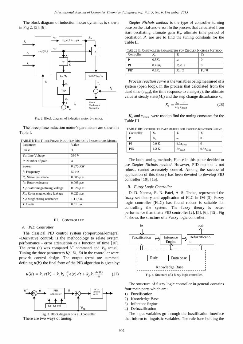
The block diagram of induction motor dynamics is shown
in Fig 2. [5], [6].
Fig. 2. Block diagram of induction motor dynamics.
The three phase induction motor’s parameters are shown in
Table I.
TABLE I: THE THREE PHASE INDUCTION MOTOR’S PARAMETERS MODEL
Parameter Value
Phase 3
Vll: Line Voltage 380 V
P: Number of pole 4
Power 0.375 KW
f : Frequency 50 Hz
Rs: Stator resistance 0.005 p.u.
Rr: Rotor resistance 0.005 p.u.
Xls: Stator magnetizing leakage 0.028 p.u.
Xlr: Rotor magnetizing leakage 0.025 p.u.
Xm: Magnetizing resistance 1.11 p.u.
J: Inertia 0.01 p.u.
III. CONTROLLER
A. PID Controller
The classical PID control system (proportional-integral
–Derivative control) is the methodology to relate system
performance - error attenuation as a function of time [10].
The error (e) was compared V* command and Vtg actual.
Tuning the three parameters Kp, Ki, Kd in the controller were
provide control design. The output terms are summed
defining 𝑢 𝑘 the final form of the PID algorithm is given by:
𝑢 𝑘 = 𝑘𝑝𝑒 𝑘 + 𝑘𝑝𝑘𝑖 𝑒(𝑡)𝑡
0𝑑𝑡 + 𝑘𝑝𝑘𝑑
𝑑𝑒 (𝑡)
𝑑𝑡 (27)
Fig. 3. Block diagram of a PID controller.
There are two ways of tuning:
Ziegler Nichols method is the type of controller turning
base on the trial-and-error. In the process that calculated from
start oscillating ultimate gain Ku, ultimate time period of
oscillation Pu are use to find the tuning constants for the
Table II.
TABLE II: CONTROLLER PARAMETERS FOR ZIEGLER NICHOLS METHOD
Controller Kp Ti Td
P 0.5Ku 0
PI 0.45Ku Pu /1.2 0
PID 0.6Ku Pu / 2 Pu / 8
Process reaction curve is the variables being measured of a
system (open loop), in the process that calculated from the
dead time (dead), the time response to change(), the ultimate
value at steady state(Mu) and the step change disturbance xo.
𝐾𝑜 =𝑥𝑜
𝑀𝑢
𝜏
𝜏𝑑𝑒𝑎𝑑 (28)
𝐾𝑜 and 𝜏𝑑𝑒𝑎𝑑 were used to find the tuning constants for the
Table III
TABLE III: CONTROLLER PARAMETERS FOR PROCESS REACTION CURVE
Controller Ko Ti Td
P Ko 0
PI 0.9 Ko 3.3𝜏𝑑𝑒𝑎𝑑 0
PID 1.2 Ko 2𝜏𝑑𝑒𝑎𝑑 0.5𝜏𝑑𝑒𝑎𝑑
The both turning methods, Hence in this paper decided to
use Ziegler Nichols method. However, PID method is not
robust, cannot accurately control. Among the successful
application of this theory has been devoted to develop PID
controller [10], [15].
B. Fuzzy Logic Controller
D. D. Neema, R. N. Patel, A. S. Thoke, represented the
fuzzy set theory and application of FLC in IM [3]. Fuzzy
logic controller (FLC) has found robust is suitable for
controlling the system. The fuzzy theory is better
performance than that a PID controller [2], [5], [6], [15]. Fig
4. shows the structure of a Fuzzy logic controller.
Fig. 4. Structure of a fuzzy logic controller.
The structure of fuzzy logic controller in general contains
four main parts which are:
1) Fuzzification
2) Knowledge Base
3) Inference Engine
4) Defuzzification
The input variables go through the fuzzification interface
that inform to linguistic variables. The rule base holding the
exp(𝑗𝑠)
𝐿𝑚/(1 + 𝜏𝑟𝑝)
0.75𝑃𝐿𝑚/𝐿𝑟 𝐿𝑚/𝜏𝑟
1/𝑝
X
÷
Motor
Mechanical
Dynamics
D
N
𝜔𝑟
𝑟
𝑒
𝑜
𝑇𝑒
𝑇𝐿
𝜆𝑑𝑟 𝐼𝑑𝑠
𝐼𝑞𝑠
𝐼𝑎
𝐼𝑏
𝐼𝑐
+
+
+
-
VVVF
Inverter
& IM
e u V*
Vtg
PID
Controller
Kp Ki Kd
Rule
base Data base
Fuzzification Inference
Engine
Defuzzificatio
n
Knowledge Base
in out
International Journal of Computer Theory and Engineering, Vol. 5, No. 6, December 2013
902

decision-making logic used to infer the fuzzy output, a
defuzzification converts the fuzzy output into a signal output.
Fig. 5. Block diagram of a Fuzzy logic controller.
Fig. 5 shows the block diagram of a Fuzzy logic controller.
The two variable input are the error of speed (e) and the
change in error of speed (e). The output (u) is voltage signal
to control the amplifier and VVVF Inverter.
C. Dynamic Signal
Tracking and regulating that importance proposes to
methodology design of system [7]. The speed error tuning to
fasted by using the fuzzy controlled [5], [6], [9]. The two
degrees of freedom that was to check the error and assisted e,
e input of Fuzzy Logic Controller (FCL). Fig. 6. shows the
compared of the command, reference and dynamics signal.
Fig. 6. Dynamics signal analysis: step command.
Our aim is to eliminate the steady state error and improve
the performance of the output response for control system.
The purposed controller we define the error e(𝑘) and change
error ∆𝑒(𝑘) as follows [9], [15]:
𝑒 𝑘 = 𝑉∗ 𝑘 − 𝑉𝑡𝑔(𝑘) (29)
∆𝑒 𝑘 = 𝑒 𝑘 − 𝑒(𝑘 − 1) (30)
a1, a5, a9: e = + and e = +, the error is positive and error
increased
a2, a6, a10: e = + and e = -, the error is positive and error
decreased
a3, a7, a11: e = - and e = -, the error is negative and error
increased
a4, a8, a12: e = - and e = +, the error is negative and error
decreased, the error is positive and error increased
D. Design of Fuzzy Tuning Speed Controller
The error (e), change in error (e) and output variable (u)
are represented as linguistic values as follows:
1) Fuzzy number
Positive Big: PB Positive Medium: PM
Positive Small: MS Zero: ZE
Negative Small: NS Negative Medium: NM
Negative Big: NB
2) Membership function
In this paper, the triangular-shaped functions were selected.
The fuzzy number and membership function is shown in Fig.
7.
Fig. 7. The membership functions.
3) Quantization levels
Fuzzy sets of a FLC shows the corresponding rule table for
the speed control. There are 7 × 7 = 49 possible rules in the
matrix, for example as follows:
If e negative small (NS) and e is positive small (PS) then
output (u) is zero (ZE).
The fuzzy inference process to calculated fuzzy output.
The Mamdani’s method that found suitable for DC machine
or Induction machine [7]. The Mamdani’s method was
convert fuzzy output into the crisp value of the output
variable. This method, the centre of area (COA)
de-fuzzification method is generally used. The crisp value of
the output variable torque is applied to the VVVF inverter.
The VVVF inverter controlled the magnitude and frequency
of the V/f to desired speed of the motor.
E. Fuzzy PID Compensation System
The PID controllers are widely, exhibit poor performance
when applied to nonlinearities [9]. However, the PID
controllers are minimized the steady state error system. The
closed loop PID controller can be used controls the speed of
DC motor [10]. A variable gain PI controller that designed to
replace the classical PI the motor reaches the reference speed
d/dt
VVVF
Inverter
& IM
e
e u V*
Vtg
a1
a2
a3
a4
a5 a6
a7 a8
a9 a10 a11 a12
+
+
+ +
+ +
-
-
- -
- -
-
-
+
+ +
-
- +
+
+ - -
e e
Command
Reference
Dynamic signal
Response
Time
-6 -4 -2 0 2 4 6 0
1
e,e
NB NM NS ZE PS PM PB
Output
(u) -6 -4 -2 0 2 4 6 0
1
NB NM NS ZE PS PM PB
e
e
NB NM NS ZE PS PM PB
NB NB NB NB NB NM NS ZE
NM NB NB NB NM NS ZE PS
NS NB NB NM NS ZE PS PM
ZE NB NM NS ZE PS PM PB
PS NM NS ZE PS PM PB PB
PM NS ZE PS PM PB PB PB
PB ZE PS PM PB PB PB PB
International Journal of Computer Theory and Engineering, Vol. 5, No. 6, December 2013
903

rapidly and without overshoot [16]. The constant flux of three
phase induction motor drives using fuzzy logic controller that
has been achieved in rise time and steady state of speed
controlled [3], [5], [6]. The robust, tracking and regulating of
induction motor drive that analysis by compensated method
[9], [17]. Hence, Fuzzy PID compensation control can
improve of the performance single loop control. The Fuzzy
PID compensation structures system is shown in the Fig. 8.
Fig. 8. Block diagram of the Fuzzy PID control system.
F. Simulation the Speed Control System
The system is modeled and implemented via LabVIEW
program is shown in Fig 9. For the turning in this paper, we
set PID gains with Ziegler Nichols and trial-error method.
The variable quantities of Kp, Ti, Td are derived by fuzzy
logic controller.
Fig. 9. The three phase induction motor model.
Experiment 1. The PI VVVF controller set references
speed = 0.6 pu, Kp = 0.045, Ki = 0.009 for the no load 0.375
kW, 3-phase induction motor started. And take load 0.5 pu. at
3 second of time.
Experiment 2. The Fuzzy PID compensation VVVF drive
set values are references speed = 0.6 pu., G1 = 3.8, G2 =
0.345, Kp = 20, Ti = 0.008 and Td = 0.001, for the no load
0.375 kW, 3-phase induction motor started. And take load 0.5
pu. at 3 second of time.
Experiment 3. The Fuzzy PID compensation VVVF drive
set values are references speed = 0.5 pu. , G1 = 3.8, G2 =
0.345, Kp = 20, Ti = 0.008 and Td = 0.001, for the no load
0.375 kW, 3-phase induction motor started. And take load 0.5
pu. at 3 second of time.
Fig. 10. The Volt/Hz controlled induction motor drive usually is a Fuzzy PID
compensation controller.
IV. RESULTS AND DISCUSSION
Fig. 11. Result of induction motor PI VVVF controller drive. The simulation
of speed, slip speed and Te with references speed = 0.6 pu., Kp = 0.045, Ki =
0.009, load 0.5 pu. at 3 sec.
The speed responses with the step speed references input
are implemented by LabVIEW program. The parameters
from table I. are used and the references speed is referred to
0.6 pu. and 0.5 pu. The first simulation is setup for the no load
0.375 kW 3- phase induction motor and take load 0.5 pu. at 3
second of time. The simulation model in LabVIEW is shown
in Fig. 9 and Fig 10. The results of PI VVVF controller drive
obtained by Kp = 0.045, Ki = 0.009 is shown in Fig. 11.
Membership function of error and change in error are the
same. The inputs of fuzzy logic controller are the error and
change in error. The variable quantities of PID parameters are
derived by fuzzy reasoning, and corresponding values for
PID control parameter are tuned (use of the Ziegler-Nichols
and trial-error method) until the output follows the set point
adequately. The proportional parameter Kp obtained between
20 and 25. The integration parameter Ki obtained between
0.008 and 0.006. The differential parameter Kd obtained
between 0.001 and 0.0015. The results of PI VVVF control
and Fuzzy PID compensation VVVF control are compared
d/dt
VVVF
Inverter
& IM
e
e V*
Vtg
PID
Ti
Kp G1
G2
d/dt
e
e G1
G2
d/dt
e
e G1
G2
Td
u
International Journal of Computer Theory and Engineering, Vol. 5, No. 6, December 2013
904
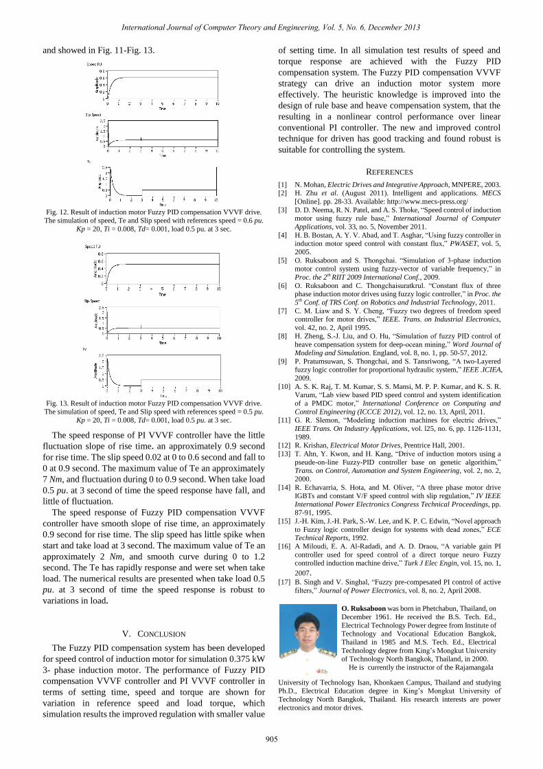
and showed in Fig. 11-Fig. 13.
Fig. 12. Result of induction motor Fuzzy PID compensation VVVF drive.
The simulation of speed, Te and Slip speed with references speed = 0.6 pu.
Kp = 20, Ti = 0.008, Td= 0.001, load 0.5 pu. at 3 sec.
Fig. 13. Result of induction motor Fuzzy PID compensation VVVF drive.
The simulation of speed, Te and Slip speed with references speed = 0.5 pu.
Kp = 20, Ti = 0.008, Td= 0.001, load 0.5 pu. at 3 sec.
The speed response of PI VVVF controller have the little
fluctuation slope of rise time. an approximately 0.9 second
for rise time. The slip speed 0.02 at 0 to 0.6 second and fall to
0 at 0.9 second. The maximum value of Te an approximately
7 Nm, and fluctuation during 0 to 0.9 second. When take load
0.5 pu. at 3 second of time the speed response have fall, and
little of fluctuation.
The speed response of Fuzzy PID compensation VVVF
controller have smooth slope of rise time, an approximately
0.9 second for rise time. The slip speed has little spike when
start and take load at 3 second. The maximum value of Te an
approximately 2 Nm, and smooth curve during 0 to 1.2
second. The Te has rapidly response and were set when take
load. The numerical results are presented when take load 0.5
pu. at 3 second of time the speed response is robust to
variations in load.
V. CONCLUSION
The Fuzzy PID compensation system has been developed
for speed control of induction motor for simulation 0.375 kW
3- phase induction motor. The performance of Fuzzy PID
compensation VVVF controller and PI VVVF controller in
terms of setting time, speed and torque are shown for
variation in reference speed and load torque, which
simulation results the improved regulation with smaller value
of setting time. In all simulation test results of speed and
torque response are achieved with the Fuzzy PID
compensation system. The Fuzzy PID compensation VVVF
strategy can drive an induction motor system more
effectively. The heuristic knowledge is improved into the
design of rule base and heave compensation system, that the
resulting in a nonlinear control performance over linear
conventional PI controller. The new and improved control
technique for driven has good tracking and found robust is
suitable for controlling the system.
REFERENCES
[1] N. Mohan, Electric Drives and Integrative Approach, MNPERE, 2003. [2] H. Zhu et al. (August 2011). Intelligent and applications. MECS
[Online]. pp. 28-33. Available: http://www.mecs-press.org/
[3] D. D. Neema, R. N. Patel, and A. S. Thoke, “Speed control of induction
motor using fuzzy rule base,” International Journal of Computer
Applications, vol. 33, no. 5, November 2011.
[4] H. B. Bostan, A. Y. V. Abad, and T. Asghar, “Using fuzzy controller in induction motor speed control with constant flux,” PWASET, vol. 5,
2005.
[5] O. Ruksaboon and S. Thongchai. “Simulation of 3-phase induction motor control system using fuzzy-vector of variable frequency,” in
Proc. the 2th RIIT 2009 International Conf., 2009.
[6] O. Ruksaboon and C. Thongchaisuratkrul. “Constant flux of three phase induction motor drives using fuzzy logic controller,” in Proc. the
5th Conf. of TRS Conf. on Robotics and Industrial Technology, 2011.
[7] C. M. Liaw and S. Y. Cheng, “Fuzzy two degrees of freedom speed controller for motor drives,” IEEE. Trans. on Industrial Electronics,
vol. 42, no. 2, April 1995.
[8] H. Zheng, S.-J. Liu, and O. Hu, “Simulation of fuzzy PID control of heave compensation system for deep-ocean mining,” Word Journal of
Modeling and Simulation. England, vol. 8, no. 1, pp. 50-57, 2012.
[9] P. Pratumsuwan, S. Thongchai, and S. Tansriwong, “A two-Layered
fuzzy logic controller for proportional hydraulic system,” IEEE .ICIEA,
2009.
[10] A. S. K. Raj, T. M. Kumar, S. S. Mansi, M. P. P. Kumar, and K. S. R. Varum, “Lab view based PID speed control and system identification
of a PMDC motor,” International Conference on Computing and
Control Engineering (ICCCE 2012), vol. 12, no. 13, April, 2011. [11] G. R. Slemon, “Modeling induction machines for electric drives,”
IEEE Trans. On Industry Applications, vol. l25, no. 6, pp. 1126-1131,
1989. [12] R. Krishan, Electrical Motor Drives, Prentrice Hall, 2001.
[13] T. Ahn, Y. Kwon, and H. Kang, “Drive of induction motors using a
pseude-on-line Fuzzy-PID controller base on genetic algorithim,” Trans. on Control, Automation and System Engineering, vol. 2, no. 2,
2000.
[14] R. Echavarria, S. Hota, and M. Oliver, “A three phase motor drive IGBTs and constant V/F speed control with slip regulation,” IV IEEE
International Power Electronics Congress Technical Proceedings, pp.
87-91, 1995.
[15] J.-H. Kim, J.-H. Park, S.-W. Lee, and K. P. C. Edwin, “Novel approach
to Fuzzy logic controller design for systems with dead zones,” ECE Technical Reports, 1992.
[16] A Miloudi, E. A. Al-Radadi, and A. D. Draou, “A variable gain PI
controller used for speed control of a direct torque neuro Fuzzy controlled induction machine drive,” Turk J Elec Engin, vol. 15, no. 1,
2007. [17] B. Singh and V. Singhal, “Fuzzy pre-compesated PI control of active
filters,” Journal of Power Electronics, vol. 8, no. 2, April 2008.
O. Ruksaboon was born in Phetchabun, Thailand, on
December 1961. He received the B.S. Tech. Ed.,
Electrical Technology Power degree from Institute of Technology and Vocational Education Bangkok,
Thailand in 1985 and M.S. Tech. Ed., Electrical
Technology degree from King’s Mongkut University of Technology North Bangkok, Thailand, in 2000.
He is currently the instructor of the Rajamangala
University of Technology Isan, Khonkaen Campus, Thailand and studying Ph.D., Electrical Education degree in King’s Mongkut University of
Technology North Bangkok, Thailand. His research interests are power
electronics and motor drives.
International Journal of Computer Theory and Engineering, Vol. 5, No. 6, December 2013
905