Fuzzy motor
31
Integrated fuzzy logic controller for a Brushless DC Servomotor system Department of Biomedical Engineering Faculty of Engineering University of Isfahan Seyed Yahya Moradi [email protected] [email protected]
-
Upload
seyed-yahya-moradi -
Category
Engineering
-
view
184 -
download
0
Transcript of Fuzzy motor

Integrated fuzzy logic controller for a Brushless DC Servomotor system
Department of Biomedical EngineeringFaculty of Engineering
University of Isfahan
Seyed Yahya [email protected]@mehr.ui.ac.ir

Outlines
• Abstract
• Problem description.
• The Mathematical Model Of the system.
• The control system.
• Conclusion
Keywords: BLDC: Brushless DC servomotorFLC: Fuzzy logic controllerIFLC: Integrated fuzzy logic controller

Abstract
• The proposed controller systems consist of two -input fuzzy integrated fuzzy logic controller (IFLC) for rotation speed control of brushless dc servomotor drive.
• The input for the controller are error e(t), and change in error (first derivative of error ce(t)) with a single-output.
• The IFLC is designed using FLC and proportional derivation integral (PID) controllers.

• The brushless dc motors (BLDC) are used in various applications such as defense, industries, robotics, etc. In these applications, the motor should be precisely controlled to give the desired performance.
• BLDC motors are relatively easy to control, and considered to be high performance motor that is capable of providing large amounts of torque over a vast speed range.
• The Torque vs. speed curve is shown in figure.1
Problem description

BLDC Motor Torque-Speed characteristics curve

The physical system structure

The mathematical model
The voltage equation of motor can be described by
The electromagnetic torque is linearly proportional to the armature current and the equation is given by:
The load torque
And the motion equation can be expressed as:


The transfer function parameters

The Block Diagram and the unity feedback response


PID controller design
S-C: Kp=2.124, Ki=29.104 C-C: Kp=0.567, Ki=2845.865
PID Time response

Increasing Friction and inertia

FLC Controller
Cd k= 1*10^(-14), Cd k1= 1000, Sat=[-6000, 6000] (optimal response)

FLC Inputs fuzzy sets and Rules using Sugeno-type reasoning and Matlab Anfis tool box


FLC Controller response


IFLC Controller
Cd k= 1*10^(-14), Sat=[-1000, 1000], C-S: Kp= 30, KI= 88.107, Kd=1.00
C-C: Kp=1.00, Ki= 350.941 (optimal response)

IFLC Time response


Conclusion
• The design and development of two-input FLC and IFLC for the speed control of brushless DC servomotor is being developed.
• Simulation results indicate that the IFLC provides the best performance in comparison with PID and conventional FLC.
• By several further tuning attempts, we got a better responses for both CFLC and IFLC as shown below:

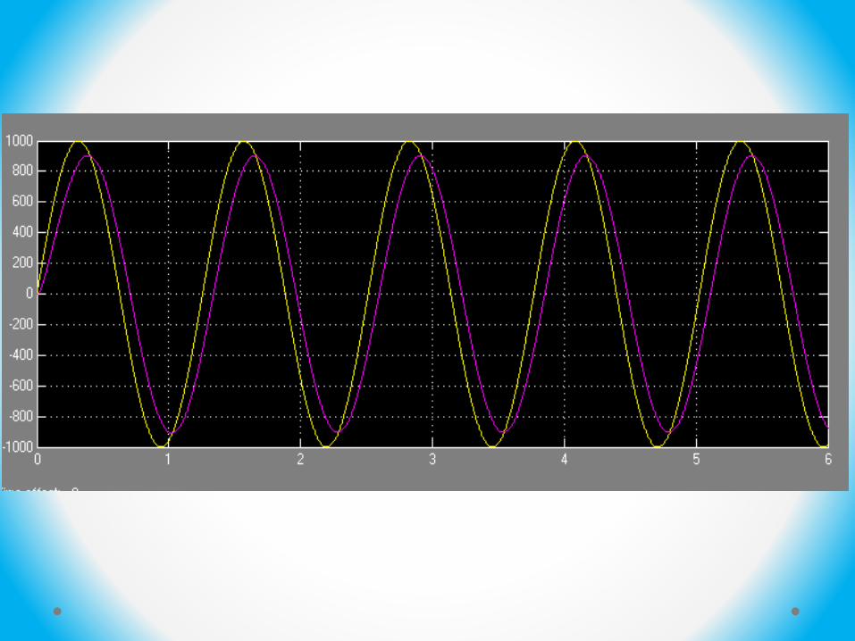
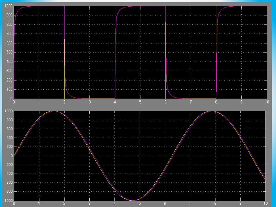
CFLC Response after several tuning attempts


IFLC Response after several tuning attempts
• The present system can further be improved by adding one more input variable (change of change of error cce). With three-input IFLC will get superior, more robust, faster, flexible, cost-effective, insensitive to the parameter variations control system , but it will require more computational time, so it’s necessary to use more powerful processing unit.

THANK YOU