Fuzzy Logic Controlled Dual Active Bridge Series … · Fuzzy Logic Controlled Dual Active Bridge...
12
Journal of Energy and Power Engineering 9 (2015) 741-752 doi: 10.17265/1934-8975/2015.08.008 Fuzzy Logic Controlled Dual Active Bridge Series Resonant Converter for DC Smart Grid Application Thabit Salim Nassor, Atsushi Yona and Tomonobu Senjyu Graduate School of Engineering and Science, University of the Ryukyus, Okinawa 903-0213, Japan Received: May 25, 2015 / Accepted: July 01, 2015 / Published: August 31, 2015. Abstract: Over the last few years, smart grids have become a topic of intensive research, development and deployment across the world. This is due to the fact that, through the smart grid, stable and reliable power systems can be achieved. This paper presents a fuzzy logic control for dual active bridge series resonant converters for DC smart grid application. The DC smart grid consists of wind turbine and photovoltaic generators, controllable and DC loads, and power converters. The proposed control method has been applied to the controllable load’s and the grid side’s dual active bridge series resonant converters for attaining control of the power system. It has been used for management of controllable load’s state of charge, DC feeder’s voltage stability during the loads and power variations from wind energy and photovoltaic generation and power flow management between the grid side and the DC smart grid. The effectiveness of the proposed DC smart grid operation has been verified by simulation results obtained by using MATLAB ® and PLECS ® cards. Key words: DC smart grid, dual active bridge series resonant converter, wind turbine, controllable loads, photovoltaic. 1. Introduction For more than five decades, the power system has heavily depended on fossil fuels, including oil, coal and natural gas, as energy sources. These fossil fuels are nonrenewable and the reserves on the earth are being consumed rapidly. Also exhaust generated from these resources is associated with the environmental destruction such as global warming and pollution [1]. Therefore, in response to these challenges, global attention has been focused on finding alternative energy resources that can sustain long-term industry development. Currently, the identified and implemented RES (renewable energy sources) include wind, hydro, solar, tidal, geothermal and waste energy. These resources are also called green energy because they do not release carbon dioxide (CO 2 ) into the atmosphere during electric energy generation and are abundant in nature. These RES are important Corresponding author: Thabit Salim Nassor, Ph.D. student, research fields: smart grid, power system control, intelligent energy management, power electronics and renewable energy. E-mail: [email protected]. substitutes of fossil fuels for their exploitation durability and environmental friendliness. In fact, this situation has brought about many research studies and deployment across the world for effective methods to harness the RES. The SG (smart grid) is a re-working of electricity infrastructures-encompassing technology, policy, and business models, which is under way globally [2]. The smart grid architecture would encompass but is not limited to distribution automation/management systems, an advanced metering infrastructure, data communication, and intelligent devices and tools for monitoring, control and optimization. By engaging in the smart grid, several challenges associated with current power and energy systems can be addressed. These include: greenhouse gas emissions and climate change, reliability, economic and energy security as explained in Ref. [2]. For better operation of electrical power systems which incorporate diversified RES, the smart grid is a critical system that determines the effectiveness and efficiency of these systems. It offers a variety of D DAVID PUBLISHING
Transcript of Fuzzy Logic Controlled Dual Active Bridge Series … · Fuzzy Logic Controlled Dual Active Bridge...

Journal of Energy and Power Engineering 9 (2015) 741-752 doi: 10.17265/1934-8975/2015.08.008
Fuzzy Logic Controlled Dual Active Bridge Series
Resonant Converter for DC Smart Grid Application
Thabit Salim Nassor, Atsushi Yona and Tomonobu Senjyu
Graduate School of Engineering and Science, University of the Ryukyus, Okinawa 903-0213, Japan
Received: May 25, 2015 / Accepted: July 01, 2015 / Published: August 31, 2015.
Abstract: Over the last few years, smart grids have become a topic of intensive research, development and deployment across the world. This is due to the fact that, through the smart grid, stable and reliable power systems can be achieved. This paper presents a fuzzy logic control for dual active bridge series resonant converters for DC smart grid application. The DC smart grid consists of wind turbine and photovoltaic generators, controllable and DC loads, and power converters. The proposed control method has been applied to the controllable load’s and the grid side’s dual active bridge series resonant converters for attaining control of the power system. It has been used for management of controllable load’s state of charge, DC feeder’s voltage stability during the loads and power variations from wind energy and photovoltaic generation and power flow management between the grid side and the DC smart grid. The effectiveness of the proposed DC smart grid operation has been verified by simulation results obtained by using MATLAB® and PLECS® cards. Key words: DC smart grid, dual active bridge series resonant converter, wind turbine, controllable loads, photovoltaic.
1. Introduction
For more than five decades, the power system has
heavily depended on fossil fuels, including oil, coal and
natural gas, as energy sources. These fossil fuels are
nonrenewable and the reserves on the earth are being
consumed rapidly. Also exhaust generated from these
resources is associated with the environmental
destruction such as global warming and pollution [1].
Therefore, in response to these challenges, global
attention has been focused on finding alternative
energy resources that can sustain long-term industry
development. Currently, the identified and
implemented RES (renewable energy sources) include
wind, hydro, solar, tidal, geothermal and waste energy.
These resources are also called green energy because
they do not release carbon dioxide (CO2) into the
atmosphere during electric energy generation and are
abundant in nature. These RES are important
Corresponding author: Thabit Salim Nassor, Ph.D. student,
research fields: smart grid, power system control, intelligent energy management, power electronics and renewable energy. E-mail: [email protected].
substitutes of fossil fuels for their exploitation
durability and environmental friendliness. In fact, this
situation has brought about many research studies and
deployment across the world for effective methods to
harness the RES.
The SG (smart grid) is a re-working of electricity
infrastructures-encompassing technology, policy, and
business models, which is under way globally [2]. The
smart grid architecture would encompass but is not
limited to distribution automation/management
systems, an advanced metering infrastructure, data
communication, and intelligent devices and tools for
monitoring, control and optimization. By engaging in
the smart grid, several challenges associated with
current power and energy systems can be addressed.
These include: greenhouse gas emissions and climate
change, reliability, economic and energy security as
explained in Ref. [2].
For better operation of electrical power systems
which incorporate diversified RES, the smart grid is a
critical system that determines the effectiveness and
efficiency of these systems. It offers a variety of
D DAVID PUBLISHING

Fuzzy Logic Controlled Dual Active Bridge Series Resonant Converter for DC Smart Grid Application
742
advantages over the current systems in terms of
digitalization, flexibility, intelligence, resilience,
sustainability and customization [3].
The DC grid has the following advantages compared
to an AC power distribution system: (1) Each power
generator connected to the DC grid can easily be used
cooperatively because the DC grid controls only the
DC bus voltage; (2) when the AC grid experiences
abnormal or fault conditions, the DC grid is
disconnected from the AC grid, and it is then switched
to stand-alone operation, in which the generated and
stored power are supplied to the loads connected to the
DC grid, hence, loads can be operated continuously
without instantaneous interruption; (3) the cost and
losses involved with the DC system can be reduced
because only a single AC grid connected inverter unit
is needed; (4) distributed generators usually supply DC
power. Therefore, the phase detection associated with
the AC grid is not needed. Thus, the cost and loss of the
system can be reduced; and (5) although a DC
distribution line is required, the cost performance of
DC houses, hospitals, and information centers are
satisfactory [4].
At present, only AC smart grids are used in practical
applications, whereby the DCSG (DC smart grid) has
been proposed by the authors [5-8]. In Refs. [5, 6], the
authors have proposed the operation of a DC MSG (DC
micro smart grid) and the multi DC smart grid in
isolated mode. However, there was no discussion on
how the DC MSG will operate in insolation mode,
especially if there is less power generation in
comparison to load demand. Moreover, the operation
in deficit or surplus power in the system was not
considered.
In Refs. [7, 8], the authors covered the earlier
mentioned cases and proposed protection of the DC
transmission line in multi DC smart grid operation,
respectively. Nevertheless, neither of the papers
considered controllable load and power flow
management during the grid connected mode of
operation.
In this paper, the fuzzy logic control has been used
for controlling PWM (pulse width modulation) delay
angle of the DABSRCs (dual active bridge series
resonant converters) for different operation conditions.
These includes: controllable load’s SOC (state of
charge) management, DC feeder’s voltage stability and
power flow management between the grid side and the
DCSG. The fuzzy logic control is used due to its
benefits compare to other controls which includes:
design simplicity, robustness and minimal requirement
for accurate mathematical model [9], can be well
implemented to low-resolution analogue to digital
converters and low-cost systems based on cheap
sensors [10].
The proposed DCSG consists of a PMSG
(permanent magnet synchronous generator) WT (wind
turbine) and PV generation, a WT generator inverter, a
PV boost converter, a GS (grid-side) and CL
(controllable load) DABSRCs, controllable loads, and
normal DC loads. During the DCSG operation, the DC
distribution line voltage fluctuations due to power
supplied by the renewable energy plants (WT and PV)
and loads are suppressed by applying the power
consumption control to the CL. In the case where the
CL cannot stabilize the system, the GS converter will
participate in power stabilization and CL management
by power transfer operation between DCSG and grid.
This paper has been organized as follows: Section 2
describes the modeling of all components of the power
system including WT and PV generators, converters
and loads with their control system. Section 3 discusses
the results, which are obtained in different operation
cases. The paper is finalized with Section 4 which will
present conclusions from this work.
2. Power System Modeling and Control
The proposed DCSG power system as shown in Fig. 1
contains a WT and PV generators, variable DC loads,
controllable loads, a generator-side converter, CWT,
PV boost converter, CPV, and bidirectional DC/DC
converters, DABSRCs, for connecting the controllable

Fuzzy Logic Controlled Dual Active Bridge Series Resonant Converter for DC Smart Grid Application
743
Fig. 1 The system configuration block diagram of the DC smart grid.
loads, CB, as well as the grid, CGS, which is connected
to DC infinity bus though DC CB (circuit breaker). The
PMSG’s and PV’s output power are supplied to the DC
loads through the DC feeder (DC distribution line).
When excess power in PMSG and PVs is generated
relative to the loads demand, it is supplied to the grid
through the grid connected converter. The grid
connected and controllable load DABSRCs control
their output power to maintain: (1) feeder’s voltage, Vdc
within a range of 5%, and (2) operation
management of controllable load power’s SOC within
the acceptable range of 80%-20% for upper and lower
limits [11]. The operations of the converters are
controlled using fuzzy logic control.
2.1 Wind Energy Conversion System
The WTG (wind turbine generator) is a gearless 2 MW
PMSG as modeled in Refs. [12-14]. The PMSG has a
simple structure and high efficiency; it is expected to
be installed in the next generation of WTG systems.
Wind power energy obtained from the windmill is sent
to the PMSG. In order to generate maximum power, the
rotational speed of the PMSG is controlled by the
PWM converter. The generator-side converter controls
the rotational speed of the PMSG in order to achieve
variable speed operation with MPPT (maximum power
point tracking) control and implements the
maximum torque control [15, 16]. Optimum
rotational speed of the PMSG used in this paper is
approximated as in Eq. (1) for MPPT [5]:
_ 2.0615e opt wV (1)
where, ωe_opt is optimum rotational speed of the PMSG
in rad/s and Vw is wind speed in m/s.
Generally, the MPPT control is applied when Vw is
smaller than the rated wind speed, Vrw. If the Vw is
greater than Vrw, then the output power of the PMSG is
controlled by the pitch angle (β) control system. When
Vw ranges between cut-in Vw (5 m/s) to rated Vw (12
m/s), the β is set to 0°, since wind windmill energy is
maximum at 0° [14], when Vw is between Vrw and the
cut-out Vw (24 m/s), the pitch angle is controlled to
deliver windmill output (Pg = 1), when the Vw is above
the cut-out Vw the β is set to 90° because the energy of
a windmill is the smallest at 90°. The control diagram
is shown in Fig. 2. The detailed pitch angle control was
described in Ref. [17].
The speed control of the PMSG is realized on a rotating
frame, where the rotational speed error from optimum
rotational speed, ωe_opt and measured rotational speed,
ωe are used as the input of the speed controller (PI1),
which produces, q axis stator current command, i1q* as
shown in Fig. 3. Generally, the salient pole type
synchronous machine is desirable to control the d-axis
stator current, i1d and the reference i1d* as expressed in
Eq. (2). 2
21 122( ) 4( )
f fd q
d q q d
i iL L L L
(2)
where, f is the permanent magnetic flux, Ld and Lq
are the dq-axis inductance, and i1q is the q-axis current.
The parameters of the PMSG and windmill are shown
in Table 1 [5].
Fig. 2 Pitch angle control system.

Fuzzy Logic Controlled Dual Active Bridge Series Resonant Converter for DC Smart Grid Application
744
Fig. 3 Generator-side converter control system.
2.2 PV System
PV generation is very important for the utilization of
renewable energy provided by the sun. A PV generator
converts solar or artificial light to electric energy due to
the movement of positive and negative charge carriers
when the light strikes its surface. Normally, the PV
generation systems suffer low energy conversion
efficiency due to non-linear variations of output
voltage and current, which is caused by environmental
and operational conditions [18]. These include:
ambient temperature, operating temperature, insulation,
dirt, sunlight characteristics and load current
technologies [18, 19]. Different methods have been
used and proposed for solving this problem, such as: (1)
sun tracking; (2) MPPT; and (3) a combination of
both [19].
Single diode PV model as in Refs. [20, 21] has been
used for modeling the PV generation system in this
research. Eq. (3) describes the output current (I) of the
PV from the model.
L DI I I (3)
where,
( )
0 ( 1)Sq V IR
nkTDI I e
1 0 1( )(1 ( ))L LI I T K T T
1,
1
( )
( )( )
nomSC T
L Tnom
GII
G
2 1( ) ( )
02 1
SC T SC TI IK
T T
where, IL is the current source which is equal to the
short circuit current, ISC and directly proportional to
solar irradiance, G (W·m2), Rs is the series resistance, I0
is the reverse saturation current of the diode, q is the
electron charge (1.60 × 10⁻¹⁹ C), Vd is the voltage across
Table 1 Parameters of wind turbine generator.
Rated power Pref 2 MW
Rated wind speed Vw_ref 12 m/s
Stator resistance Ra 0.01 pu
Leakage inductance Lls 0.1 pu
Stator d/q axis inductance Ld, Lq 1/0.65 pu
Number of pole pairs p 11
Field flux K 136.25 Wb
Radius of wind turbine rotor R 38 m
Equivalent inertia Jeq 8,000 kg·m2
Rotational damping D 0
the diode, k is Boltzmann constant (1.38 × 10⁻²³ J/K), T
is the junction temperature (K), T1 is the standard PV
designed temperature (25 °C), T2 is the ambient
temperature (°C) and n is the diode ideality factor.
In this paper, in order to generate maximum and
optimum power from the PV system as the temperature,
insolation and load varies, a maximum power point
tracker has been implemented to DC/DC boost
converter connected between the PV system and
distribution line as shown in Fig. 4. The PV modules
have been modeled and arranged in parallel and series
to give out power of 1 MW. The PV module has been
modeled as of BP365 65 W with the specifications
shown in Table 2.
Fig. 4 PV system model.
Table 2 Specifications of the BP365 65 W PV module.
Maximum power Pm 65 W
Voltage, max power Vm 17.6 V
Current, max power Im 3.69 A
Open circuit voltage VOC 22.1 V
Short circuit current Isc 3.99 A

Fuzzy Logic Controlled Dual Active Bridge Series Resonant Converter for DC Smart Grid Application
745
2.3 Controllable Loads
In this paper, the DC feeder voltage is maintained by
the voltage control of the DC/DC converter connected
to the controllable loads. Batteries are used as
controllable loads. Although the battery is installed in
DC houses, the EV (electric vehicle) will be also used
as a battery in the future. The EV is important due to
the depletion of energy sources and its availability as a
backup power in the residential houses.
The battery is modeled as from Refs. [22, 23].
Terminal voltage, Eb and state of charge, SOC are
calculated by Eqs. (4) and (5), respectively. A 940 V/1 kAh
battery was modeled and used in the power system. In
order to show all simulation condition results with high
and low battery capacity, the charging and discharging
time constant of 14 s was used instead of actual time of
1 h (3,600 s).
(- d )0 +
dbB i t
b b b
b
QE E R i K Ae
Q i t
(4)
d100(1 )
bi tSOC
Q (5)
where, E0 is the battery constant voltage (V), Rb is
internal resistance of the battery (Ω), ib is the battery
charging current (A), Q is the battery capacity (Ah), K
is the polarization voltage (V), A is exponential voltage
(V) and B is the exponential capacity (1/Ah).
2.4 Bidirectional Converter
The bidirectional converters chosen in this study to
connect the controllable loads and grid bus to the DC
distribution line are DABSRC as shown in Fig. 5.
DABSRC has been chosen due to its numerous
advantages such as, small size, low cost, simple control
and high power density [24, 25]. Ref. [26] mentioned
different modulation methods for these converters. In
this paper, phase shift modulation was used. Among
the advantages of this method are low complexity of
computations for the phase shift method, simplicity of
the circuit, and a reduction of power loss due to ZVS
(zero voltage switching) [27].
The detailed AC analysis of this converter was
described in Refs. [24, 25]. The output active power, P0
which is the average value of instantaneous power,
tank parameters, inductor, Ls and capacitor, Cs are
given by Eqs. (6)-(8), respectively.
2π0, 0
2
1 8( )d( ) sin
12π π ( )pu pu s
MP P t t
Q FF
(6)
'r s
L
LQ
R
(7)
2πs s
s sr
fF
L C
(8)
where,
' 20
1
/ i t
EM V V n
E
'LR is the load resistance transferred to the primary
side, ωr is angular resonant frequency, fs is switching
frequency, nt:1 is transformer turns ratio, '0V is output
voltage transferred to the primary side, Vi is primary
input voltage and φ is phase shift angle.
Eq. (6) can be used to determine φ for the amount of
power delivered to either side of the converter, whereas
the net power flow is positive with φ > 0 and negative
with φ < 0. In Refs. [24, 25], the design curves were
used to obtain the optimized values of voltage gain, (M
= 0.95), normalized frequency, (F = 1.1), and value of
Q which is equal to 1 for achieving soft switching,
lower resonant current, high efficiency and small tank
size. Table 3 shows the design parameters for
controllable load and grid side bidirectional converters.
2.4.1 Fuzzy Logic Control Strategy for DABSRCs
Fuzzy logic is used in this paper for controlling the
phase shift angle of the PWM of bidirectional
converters. In controllable load’s DABSRC, the fuzzy
Fig. 5 Dual active bridge series resonant converter.
Fuzzy Logic Controlled Dual Active Bridge Series Resonant Converter for DC Smart Grid Application
746
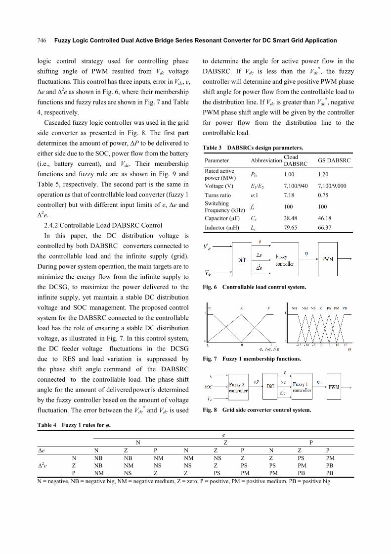
logic control strategy used for controlling phase
shifting angle of PWM resulted from Vdc voltage
fluctuations. This control has three inputs, error in Vdc, e,
∆e and ∆2e as shown in Fig. 6, where their membership
functions and fuzzy rules are shown in Fig. 7 and Table
4, respectively.
Cascaded fuzzy logic controller was used in the grid
side converter as presented in Fig. 8. The first part
determines the amount of power, ∆P to be delivered to
either side due to the SOC, power flow from the battery
(i.e., battery current), and Vdc. Their membership
functions and fuzzy rule are as shown in Fig. 9 and
Table 5, respectively. The second part is the same in
operation as that of controllable load converter (fuzzy 1
controller) but with different input limits of e, ∆e and
∆2e.
2.4.2 Controllable Load DABSRC Control
In this paper, the DC distribution voltage is
controlled by both DABSRC converters connected to
the controllable load and the infinite supply (grid).
During power system operation, the main targets are to
minimize the energy flow from the infinite supply to
the DCSG, to maximize the power delivered to the
infinite supply, yet maintain a stable DC distribution
voltage and SOC management. The proposed control
system for the DABSRC connected to the controllable
load has the role of ensuring a stable DC distribution
voltage, as illustrated in Fig. 7. In this control system,
the DC feeder voltage fluctuations in the DCSG
due to RES and load variation is suppressed by
the phase shift angle command of the DABSRC
connected to the controllable load. The phase shift
angle for the amount of delivered power is determined
by the fuzzy controller based on the amount of voltage
fluctuation. The error between the Vdc* and Vdc is used
to determine the angle for active power flow in the
DABSRC. If Vdc is less than the Vdc*, the fuzzy
controller will determine and give positive PWM phase
shift angle for power flow from the controllable load to
the distribution line. If Vdc is greater than Vdc*, negative
PWM phase shift angle will be given by the controller
for power flow from the distribution line to the
controllable load.
Table 3 DABSRCs design parameters.
Parameter Abbreviation Cload DABSRC
GS DABSRC
Rated active power (MW)
P0 1.00 1.20
Voltage (V) E1/E2 7,100/940 7,100/9,000
Turns ratio n:1 7.18 0.75 Switching Frequency (kHz)
fs 100 100
Capacitor (μF) Cs 38.48 46.18
Inductor (mH) Ls 79.65 66.37
Fig. 6 Controllable load control system.
Fig. 7 Fuzzy 1 membership functions.
Fig. 8 Grid side converter control system.
Table 4 Fuzzy 1 rules for φ.
e
N Z P Δe N Z P N Z P N Z P
Δ2e N NB NB NM NM NS Z Z PS PM Z NB NM NS NS Z PS PS PM PB P NM NS Z Z PS PM PM PB PB
N = negative, NB = negative big, NM = negative medium, Z = zero, P = positive, PM = positive medium, PB = positive big.

Fuzzy Logic Controlled Dual Active Bridge Series Resonant Converter for DC Smart Grid Application
747
Fig. 9 Fuzzy 2 membership functions.
Table 5 Fuzzy 2 rules for ΔP0.
Vdc
H N L
ib BN BN SN Z SP BP BP
SOC
VL VSN VSP SP BP VBP VBP VBP
L SN Z Z Z Z Z LP
N SN Z Z Z Z Z SP
H BN Z Z Z Z Z SP
VH VBN VBN VBN BN SN VSN VSP
VBN = very big negative, BN = big negative, SN = small negative, Z = zero, SP = small positive, BP = big positive, VBP = very big positive, VL = very low, L = low, N = normal, H = high, VH = very high.
2.4.3 Grid Side DABSRC Control
With a surfeit or deficit of power generation over
the load demand, or when the SOC management of the
controllable load is needed, the grid connected
DABSRC is controlled to stabilize the power system.
By power transfer operation between the DCSG and
the grid, distribution line voltage stabilization and SOC
management are guaranteed. In the case of power
transfer, when excess power is generated or a
deficiency of power occurs in a DCSG, the amount of
the power to be transferred to either side is determined
by the fuzzy controller shown in Fig. 8. The first part
determines the amount of power, ∆P to be delivered to
either side and thesecond part is fixing PWM shift
angle corresponding to the calculated ∆P. Therefore,
Vdc of the DCSG is also controlled according to the
energy transfer between DCSG and grid side when the
grid side converter is in operation.

Fuzzy Logic Controlled Dual Active Bridge Series Resonant Converter for DC Smart Grid Application
748
3. Simulation Results
The simulation of the power system model in Fig. 1
has been carried out for different operation cases of the
DCSG. Figs. 10 and 11 present the wind speed and
solar insolation for WT and PV power generation. The
generated active power from WT (PWT), PV (PPV) and
their summation (PTG) are presented in Figs. 12-14,
respectively.
Furthermore, Fig. 15 shows three DC loads (PL) with
a maximum consumption of 1 MW each switched in
different capacities to show the effectiveness of the
power system, while Fig. 16 describes the total
combined DC load (PTL) as seen by the control system
during operation. For power stabilization in the DCSG,
due to power generation and load variation during
simulation, the controllable load converter phase shift
angle (φCL) is shown in Fig. 17 and its corresponding
active power output (PCL) is shown in Fig. 18. Whereas,
a phase shift angle of grid converter (φG) is shown in
Fig. 19 with its active output power (PG) in Fig. 20.
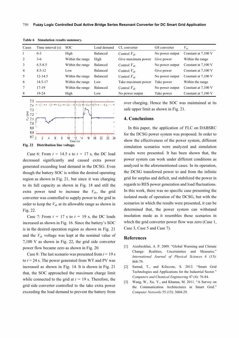
Moreover, despite the power generation and load
variations, Fig. 21 shows that, the SOC of the battery is
well maintained within acceptable operating
boundaries and also the distribution line voltage, Vdc
always stays within acceptable limits of 5% of Vdc
as shown in Fig. 22.
Time (s)
Fig. 10 Wind turbine speed.
Time (s)
Fig. 11 Solar insolation.
Time (s)
Fig. 12 Wind turbine active power.
Time (s)
Fig. 13 Photovoltaic active power.
Time (s)
Fig. 14 Total active power generation.
Time (s)
Fig. 15 DC loads .
Time (s)
Fig. 16 Total DC loads.
Apart from that, in the simulation results shown
from Figs. 10-22, different scenarios have been tested
during the simulation to show how the power system
will react in response to changes in power generation,
load variation and the on-line battery SOC. These
Sol
ar in
sola
tion
(pu
)
PW
T (
MW
) P
PV (
MW
) P
TG (
pu)
PL (
MW
) P
TL (
MW
)
Win
d sp
eed
(pu)

Fuzzy Logic Controlled Dual Active Bridge Series Resonant Converter for DC Smart Grid Application
749
scenarios are explained from Case 1 to Case 8 (C1-C8),
and their summaries are presented in Table 4.
Case 1: This case presents the operation mode of
DCSG in which the power generated from WT and PV,
and load demand are balanced as shown in the
simulation results from t = 0 s to t = 3 s. Different DC
load capacities have been switched in order to show the
demand response operation of the system. Since the
SOC of the controllable load (battery) is high and the
load power demand can be fulfilled by the controllable
load alone, hence the output power of the grid
converter is kept at zero as shown in Fig. 20 and Vdc is
kept constant at the nominal value of 7,100 V as shown
in Fig. 22. Therefore, the Vdc voltage is kept within the
acceptable range in isolated mode.
Case 2: This scenario is shown in the simulation
results from t = 3 s to t = 6 s. In this case, even though
the SOC is within the desired operating region as
shown in Fig. 21, the Vdc in Fig. 22 starts to drop due to
insufficient power from controllable loads, which are
operating at maximum output power as shown in Fig. 18,
and low power generation from the RES, as shown in
Fig. 14. Hence, the grid converter gives power to the
DCSG as shown in Fig. 20 so that the Vdc is maintained
at the accepted range.
Case 3: From t = 6 s to t = 8.5 s, power generation
increases as shown in Fig. 14. Since the SOC is within
the desired operating region as shown in Fig. 21, and
the batteries can be used to stabilize Vdc and maintain it
constant at the nominal value of 7,100 V as shown in
Fig. 22, therefore, the grid converter power output to
the DCSG was abstained.
Case 4: From t = 8.5 s to t = 12 s though the battery
can still supply power to stabilize the Vdc at 7,100 V, at
t = 8.5 s the lower limit of the SOC was approached as
shown in Fig. 21. The grid converter was controlled to
give power to the DCSG so that SOC can be improved.
Case 5: In this case, the SOC has been improved
enough for the battery alone to control the Vdc
fluctuations as shown in Fig. 21 from t = 12 s to t =
14.5 s. Since the Vdc is kept at 7,100 V by the
controllable load converter as shown in Fig. 22,
therefore, the grid converter gives no power to the
DCSG as shown in Fig. 20.
Time (s)
Fig. 17 Phase shift angle of controllable load converter.
Time (s)
Fig. 18 Controllable load active power.
Time (s)
Fig. 19 Phase shift angle of grid converter (φG: φ of grid side converter).
Time (s)
Fig. 20 Grid converter active power.
Time (s)
Fig. 21 Controllable load SOC.
φ CL (°
) P
CL (
MW
) φ G
(°)
P
G (
MW
) SO
C (
%)
Fuzzy Logic Controlled Dual Active Bridge Series Resonant Converter for DC Smart Grid Application
750
Table 6 Simulation results summary.
Time (s)
Fig. 22 Distribution line voltage.
Case 6: From t = 14.5 s to t = 17 s, the DC load
decreased significantly and caused extra power
generated exceeding load demand in the DCSG. Even
though the battery SOC is within the desired operating
region as shown in Fig. 21, but since it was charging
to its full capacity as shown in Fig. 18 and still the
extra power tend to increase the Vdc, the grid
converter was controlled to supply power to the grid in
order to keep the Vdc at its allowable range as shown in
Fig. 22.
Case 7: From t = 17 s to t = 19 s, the DC loads
increased as shown in Fig. 16. Since the battery’s SOC
is in the desired operation region as shown in Fig. 21
and the Vdc voltage was kept at the nominal value of
7,100 V as shown in Fig. 22, the grid side converter
power flow became zero as shown in Fig. 20.
Case 8: The last scenario was presented from t = 19 s
to t = 24 s. The power generated from WT and PV was
increased as shown in Fig. 14. It is shown in Fig. 21
that, the SOC approached the maximum charge limit
while connected to the grid at t = 19 s. Therefore, the
grid side converter controlled to the take extra power
exceeding the load demand to prevent the battery from
over charging. Hence the SOC was maintained at its
safe upper limit as shown in Fig. 21.
4. Conclusions
In this paper, the application of FLC on DABSRC
for the DCSG power system was proposed. In order to
show the effectiveness of the power system, different
simulation scenarios were analyzed and simulation
results were presented. It has been shown that, the
power system can work under different conditions as
analyzed in the aforementioned cases. In its operation,
the DCSG transferred power to and from the infinite
grid for surplus and deficit, and stabilized the power in
regards to RES power generation and load fluctuations.
In this work, there was no specific case presenting the
isolated mode of operation of the DCSG, but with the
scenarios in which the results were presented, it can be
determined that, the power system can withstand
insolation mode as it resembles those scenarios in
which the grid converter power flow was zero (Case 1,
Case 3, Case 5 and Case 7).
References
[1] Aizebeokhai, A. P. 2009. “Global Warming and Climate
Change: Realities, Uncertainties and Measures.”
International Journal of Physical Sciences 4 (13):
868-79.
[2] Samad, T., and Kiliccote, S. 2012. “Smart Grid
Technologies and Applications for the Industrial Sector.”
Computers and Chemical Engineering 47 (4): 76-84.
[3] Wang, W., Xu, Y., and Khanna, M. 2011. “A Survey on
the Communication Architectures in Smart Grid.”
Computer Networks 55 (15): 3604-29.
Cases Time interval (s) SOC Load demand CL converter GS converter Vdc
l 0-3 High Balanced Control Vdc No power output Constant at 7,100 V
2 3-6 Within the range High Give maximum power Give power Within the range
3 6.5-8.5 Within the range Balanced Control Vdc No power output Constant at 7,100 V
4 8.5-12 Low Balanced Control Vdc Give power Constant at 7,100 V
5 12-14.5 Within the range Balanced Control Vdc No power output Constant at 7,100 V
6 14.5-17 Within the range Low Take maximum power Take power Within the range
7 17-19 Within the range Balanced Control Vdc No power output Constant at 7,100 V
8 19-24 High Low No power output Take power Constant at 7,100 V
Vdc
(pu
)

Fuzzy Logic Controlled Dual Active Bridge Series Resonant Converter for DC Smart Grid Application
751
[4] Ito, Y., Yang, Z., and Hirofumi, A. 2009. “A Control Method for Small-Scale DC Power Systems Including Distributed Generators.” Electrical Engineering in Japan 167 (2): 1236-42.
[5] Kurohane, K., Senjyu, T., Yona, A., Urasaki, N., Goya, T.,
and Funabashi, T. 2010. “A Hybrid Smart ac/dc Power
System.” IEEE Transactions on Smart Grid 1 (2):
199-204.
[6] Yamauchi, H., Kina, M., Kurohane, K., Uchida, K., Yona,
A., and Senjyu, T. 2011. “Operation Principle of Multiple
DC Smart Grids.” In Proceedings of the 2011 IEEE Ninth
International Conference on PEDS (Power Electronics
and Drive Systems), 304-9.
[7] Nassor, T., Ziadi, Z., Yona, A., Senjyu, T., and
Abdel-Akher, M. 2012. “Comprehensive Analysis of DC
Smart Grid Operation.” In Proceedings of the 2012 IEEE
International PECon (Conference on Power and Energy),
880-5.
[8] Nassor, T. S., Kina, M., Senjyu, T., Yona, A., and
Funabashi, T. 2012. “Operation of Multi DC Smart
Grids Based on Renewable Energy Sources and
Protection of DC Transmission Line.” International
Journal of Emerging Electric Power Systems 13 (3):
1553-779.
[9] Balamurugan, T., and Manoharam, S. 2012. “Fuzzy
Controller Design Using Soft Switching Boost Converter
for MPPT in Hybrid System.” International Journal of
Soft Computing and Engineering 2 (5): 87-94.
[10] Yong, Y., Xing, L., Shen, G., Zude, Z., and Jihong, W.
2008. “A Battery Charging Control Strategy for
Renewable Energy Generation Systems.” In Proceedings
of the WCE (World Congress on Engineering),
356-61.
[11] Neeraj, S., Bohn, T., Duoba, M., Lohse-Busch, H., and
Sharer, P. 2007. “PHEV ‘All Electric Range’ and Fuel
Economy in Charge Sustaining Mode for Low SOC
Operation of the JCS VL41M Li-ion Battery Using
Battery HIL.” Argonne National Laboratory. Accessed
July 04, 2015.
http://www.transportation.anl.gov/pdfs/HV/463.pdf.
[12] Hu, W., Chen, Z., Wang, Y., and Wang, Z. 2008. “Wind
Power Fluctuations Mitigation by DC-Link Voltage
Control of Variable Speed Wind Turbines.” In
Proceedings of the 43rd International UPEC
(Universities Power Engineering Conference), 1-5.
[13] Haque, M., Muttaqi, K., and Negnevitsky, M. 2008.
“Control of a Stand Alone Variable Speed Wind Turbine
with a Permanent Magnet Synchronous Generator.” In
Proceedings of the Power and Energy Society General
Meeting—Conversion and Delivery of Electrical Energy
in the 21st Century, 1-9.
[14] Rosyadi, M., Muyeen, S. M., Takahashi, R., and Tamura, J.
2012. “A Design Fuzzy Logic Controller for a Permanent
Magnet Wind Generator to Enhance the Dynamic Stability
of Wind Farms.” Applied Sciences 2 (5): 780-800.
[15] Wu, F., Zhang, X. P., and Ju, P. 2009. “Small Signal
Stability Analysis and Control of the Wind Turbine with
the Direct-Drive Permanent Magnet Generator Integrated
to the Grid.” Electric Power Systems Research 79 (12):
1661-7.
[16] Hansen, A. D., and Michalke, G. 2008. “Modelling
and Control of Variable-Speed Multi-pole Permanent
Magnet Synchronous Generator Wind Turbine.” Wind
Energy 11 (5): 537-54.
[17] Senjyu, T., Sakamoto, R., Urasaki, N., Funabashi, T.,
Fujita, H., and Sekine, H. 2006. “Output Power Leveling
of Wind Turbine Generator for All Operating Regions by
Pitch Angle Control.” IEEE Transactions on Energy
Conversion 21 (2): 467-75.
[18] Rahmani, R., Seyedmahmoudian, M., Mekhilef, S., and
Yusof, R. 2013. “Implementation of Fuzzy Logic
Maximum Power Point Tracking Controller for
Photovoltaic System.” Journal of Electrical and
Electronics Engineering 10 (3): 209-18.
[19] Chung, H. H., Tse, K. K., Hui, S., Mok, C. M., and Ho, M.
T. 2003. “A Novel Maximum Power Point Tracking
Technique for Solar Panels Using a Sepic or Cuk
Converter.” IEEE Transactions on Power Electronics 18
(3): 717-24.
[20] Walker, G. 2001. “Evaluating MPPT Converter
Topologies Using a MATLAB PV Model.” Journal of
Electrical and Electronics Engineering 21 (1): 49-56.
[21] Agarwal, V., and Vishwakarma, A. 2009. “A Modified
Method for Maximum Power Point Tracking of PV Cell.”
Journal of Electrical and Electronic Systems Research 2
(June): 2161-5.
[22] Tremblay, O., Dessaint, L. A., and Dekkiche, A. I. 2007.
“A Generic Battery Model for the Dynamic Simulation of
Hybrid Electric Vehicles.” In Proceedings of the VPPC
(Vehicle Power and Propulsion Conference), 284-9.
[23] Pang, S., Farrell, J., Du, J., and Barth, M. 2001. “Battery
State-of-Charge Estimation.” In Proceedings of the
American Control Conference, 1644-9.
[24] Li, X., and Bhat, A. K. S. 2008. “AC Equivalent
Circuit Analysis for High-Frequency Isolated Dual-Bridge
Series Resonant DC/DC Converter.” In Proceedings of
the PESC (Power Electronics Specialists Conference),
238-44.
[25] Li, X., and Bhat, A. K. S. 2010. “Analysis and Design of
High-Frequency Isolated Dual-Bridge Series Resonant
DC/DC Converter.” IEEE Transactions on Power
Electronics 25 (4): 850-62.

Fuzzy Logic Controlled Dual Active Bridge Series Resonant Converter for DC Smart Grid Application
752
[26] Krismer, F., Round, S., and Kolar, J. 2006. “Performance
Optimization of a High Current Dual Active Bridge with a
Wide Operating Voltage Range.” In Proceedings of the
37th IEEE PESC (Power Electronics Specialists
Conference), 1-7.
[27] Biela, J., Aggeler, D., Inoue, S., Akagi, H., and Kolar, J. 2008. “Bi-directional Isolated DC-DC Converter for Next-Generation Power Distribution Comparison of Converters Using Si and SiC Devices.” The Institute of Electrical Engineers of Japan 128 (7): 1-10.