Fuses - System Controls & Switchgears. Cat.-Fuses-BS Fuses … · fully rated in accordance with...
16
179 High Voltage HBC Fuselinks 163 Semi Conductor Fuselinks Fuses 139 Low Voltage HBC Fuselinks 159 Fuse Bases 197 Fuse Distribution Boards
-
Upload
nguyenlien -
Category
Documents
-
view
217 -
download
1
Transcript of Fuses - System Controls & Switchgears. Cat.-Fuses-BS Fuses … · fully rated in accordance with...

179High Voltage HBC Fuselinks
163Semi Conductor Fuselinks
Fuses
139Low Voltage HBC Fuselinks
159Fuse Bases
197Fuse Distribution Boards

GE imagination at work

Low Voltage HBC Fuselinks
Salient Features
●
In the event of a damaging short-circuit, the fault energy is severely restricted by rapid fuselink operation.
●
The fuselinks limit the amount of electromagnetic stress thereby reducing mechanical damage to current carrying components.
●
Proven technology and expertise has ensure d guaranteed performance over many decades.
● Uninterrupted service in various environment with no change in tripping Characteristics.
●
Provides accurate discrimination between the upstream & downstream thereby ensuring uninterrupted supply in healthy feeders
●
The fuselinks provide type 2 co-ordination.
●
An early cut off ensures optimization of cable size & connected equipment, thereby reducing cost.
●
Fuselinks having time/current characteristics which are suitable for motor circuits are available. They withstand motor starting surges without deterioration / Nuisance tripping.
●
The Fuses have very low watt-loss, ensuring conservation of energy.
ApprovalApproved by the Bureau of Indian Standards and bear ISI marking as a mark of superior quality.
High breaking capacity and energy limitation
Restriction of electromagnetic stress
Reliability
Non-deterioration
Accurate discrimination
Reliable short-circuit and back up protection
Current Limiting Design
Motor circuit capability
Low Watt Loss
High breaking capacity and energy limitation
Range - 2A to 800A , 415 V / 660 V AC in bolted & clip-on version Ref Std IS 13703 - 1 & 2 - 1993 / IEC 269 / BS 88Breaking Capacity - 80 kA
EE
139
Low Voltage HBC fuselinks - BS Type

Range :Voltage and current as per table below. All have breaking capacity of 80 kA at the respective voltages indicated.
APPLICATIONSteady-load circuitsThe HBC fuselink selected should have a current rating not less than the normal full-load current of the circuit.Complete Cable ProtectionClass ‘gG’ ‘T’ range fuselinks provide complete protection and enable cables to be fully rated in accordance with IEE wiring regulations for electrical installation (16th edition).Both overload and short-circuit protection are provided if the current rating of the fuselink is equal to or less than, the current rating of the cable.In some circuits, like motor applications, it is not economical to match fuselink and cable ratings to provide complete cable protection, because of the significant over-currents produced during switching. In such cases, the fuselinks are chosen to provide only short-circuit protection to the associated cables and other circuit components, the necessary over-load protection being provided by other means.
Discrimination between Fuselinks
Positive discrimination under ‘short-circuit’ conditions is achieved when the larger or ‘major’ fuselink is unaffected by the fault current which caused the smaller or ‘minor’
2fuselink to operate. The total operating l t let through by the ‘minor’ fuselink must therefore
2be less than the pre-arching l t of the ‘major’ fuselinks.
Low Voltage HBC Fuselinks
EE
140
Low Voltage HBC fuselinks - BS Type

Ambient Air Temperatures
IS 13703-1993/ IEC 269-1986 on HBC fuselinks requires the fuselinks to be 0suitable for use in ambient air temperatures not exceeding 40 C and
recognises that derating may be necessary at higher ambient temperatures.
HBC fuselinks in ratings up to 63Amp. can be used at full rating in ambient 0temperatures up to 60 C (in most cases even higher) and ratings 63Amp. to
0160Amp. can be used in full rating in ambient temperatures up to 50 C.
The table 1 gives the derating of fuselinks at higher ambients.
These assume that the temperature inside the fuse enclosure is not more than 015 C,above ambient air temperature. If the difference between enclosure
0temperature and ambient temperature exceeds 15 C, the enclosure temperature should be used to assess derating.
0To obtain comparative enclosure temperature add 15 C to the figures in Table 1.
This table applies only for continuous loads. Where fuse ratings are chosen in motor, capacitor and transformer applications, additional deration is necessary in most cases.
Capacitor Circuits
HBC fuselinks are widely used to protect against rupture of the capacitor case and to protect cables and associated equipment from damage in the event of capacitor failure.
The fuselink selected must be capable of withstanding a normal full-load current higher than that calculated from the kVA rating (because of circuit hormonics) as well as the high transient current which occurs at ‘switch on’.
It has been proved in practice that these requirements are catered for by selecting a fuselink with a current rating not less than 1.5 times the rated capacitor current. These recommendations refer to three-phase power factor correction capacitors.
Low Voltage HBC Fuselinks
EE
141
Low Voltage HBC fuselinks - BS Type

Selecting GE Power Controls HBC fuselinks for the protection of3-Phase Induction Motors
Motor starting conditions
Example
The recommended rating of GE Power Controls HBC fuselink for a given motor starting duty can be readily obtained by the application of the data set out in Table 2, as illustrated in the example and should be adjusted to suit the starting conditions as indicated below.
Suitable adjustments to the recommended ratings should be made to allow for the following special conditions which may occur either singly or in combination.- Starting currents in excess of the assumed ones.- A large no. of starts in rapid succession. The recommendation below allows
for 2 starts in rapid succession and upto 8 starts per hour.0- Ambient temperatures in excess of 40 C
- Long run-up time due to high inertia loads.Any additional information and assistance which may be required regarding the application will be made available on receipt of the relevant details regarding circuit and operating conditions.
To find the correct fuselink for a 20 H.P. 415 Volt 3 phase induction motor with direct-on-line (DOL) starting:- full load current 28 Amp.- In Table 2 under the heading ‘Direct-on-line start,’ against the full load current
of 28Amp, the fuselink rating is 63 Amp.
Warning
- Do not use wires as replacement for blown HBC fuselinks. Arcing takes place inside HBC fuse cartridge during fault and hence your installation is safe. Bare wire will vapourise and bridge the contacts inside the equipments. This may cause explosion and danger to personnel.
- Buy fuselinks only from Authorised Dealers of
GE Power Controls India (list available at our offices) to avoid purchase of spurious and rewired fuselinks.
- Do not auction blown HBC fuselinks as these are the raw materials for spurious fuselinks. Break the blown HBC fuselinks and sell the caps, tags and elements as scrap.
Low Voltage HBC Fuselinks
EE
142
Low Voltage HBC fuselinks - BS Type

Low Voltage HBC Fuselinks
EE
143
Low Voltage HBC fuselinks - BS Type Overall Dimensions

Low Voltage HBC Fuselinks
EE
144
Low Voltage HBC fuselinks - BS Type Overall Dimensions

Low Voltage HBC Fuselinks
EE
145

Low Voltage HBC Fuselinks
EE
146

Low Voltage HBC Fuselinks
EE
147
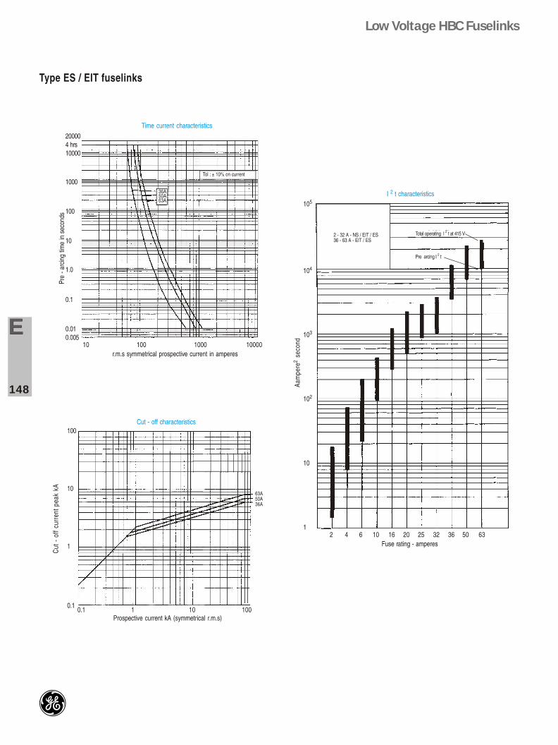
Low Voltage HBC Fuselinks
EE
148

Low Voltage HBC Fuselinks
EE
149

Low Voltage HBC Fuselinks
EE
150

Low Voltage HBC Fuselinks
EE
151

Low Voltage HBC Fuselinks
EE
152