Fuses and relays - autostellecar.files.wordpress.com
16
Fuses and relays 4-1 PASSENGER COMPARTMENT FUSE BOX (1016) location This fuse box is located in the passenger compartment on the driver’s side. Fuse symbols on vehicles produced before 16 June 2003. 28 32 36 38 39 34 35 37 33 UCH 30 31 29 ABS SE2107 22 25 27 12 16 19 20 21 24 23 26 10 11 15 14 18 17 UCH 4 8 STOP 2 3 6 7 9 13 1 5 Fuse symbols on vehicles produced after 16 June 2003. 28 32 36 38 39 34 35 37 33 30 31 29 SE2234 22 25 27 12 16 19 20 21 24 23 26 10 11 15 14 18 17 4 8 2 3 6 7 9 13 1 5 Allocation of fuses (according to equipment level) No. Symbol Amps Description F1 15A Airbag (756) F2 15A Brake lights (160) - Instrument panel (247) Eco/Perf control (129) - Diagnostic socket (225) - Driving school (469) - Opening warning (771) - Cruise control / Speed limiter control (1081) - Car phone connection (R251) - Heated door mirror control (134) for vehicles produced after 16 June 2003
Transcript of Fuses and relays - autostellecar.files.wordpress.com

Fuses and relays
4-1
PASSENGER COMPARTMENT FUSE BOX (1016)
location This fuse box is located in the passenger compartment on the driver’s side. Fuse symbols on vehicles produced before 16 June 2003.
28
32
363839
3435
37
33
UCH
3031 29
ABS
SE2107
22
25
27
12
16
19
2021
24 23
26
1011
15 14
18 17
UCH
4
8
STOP23
67
9
13
1
5
Fuse symbols on vehicles produced after 16 June 2003.
28
32
363839
3435
37
33
3031 29
SE2234
22
25
27
12
16
19
2021
24 23
26
1011
15 14
18 17
4
8
23
67
9
13
1
5
Allocation of fuses (according to equipment level)
No. Symbol Amps Description
F1
15A Airbag (756)
F2
15A Brake lights (160) - Instrument panel (247) Eco/Perf control (129) - Diagnostic socket (225) - Driving school (469) - Opening warning (771) - Cruise control / Speed limiter control (1081) - Car phone connection (R251) - Heated door mirror control (134) for vehicles produced after 16 June 2003

Fuses and relays
4-2
No. Symbol Amps Description
F3
15A Windscreen wiper compound control (145) - Reversing lights switch (155) - Air conditioning control panel (319) - Passenger compartment temperature sensor fan (418) - Air conditioning control unit (419) - Footwell vents air conditioning distribution motor (1115) - Rain sensor computer (1124) - Starter relay (232) - Discharge bulb ECU (989) - Headlight adjuster motors (537-538)
F4
20A Windscreen wiper (145)
F5
10A ABS system (118-1094)
F6
10A Multi-timer unit (645) - Air conditioning computer (419)
F7
15A Radio (261) - Cigarette lighter (101) - Clock (210) (653) - Courtesy mirror
(588) - Heated rear screen relay (235) - Central communication unit (1125)
F8 15A Horn (105)
F9
15A Left-hand dipped headlight (226-226-562-989)
F10
15A Right-hand dipped headlight (226-227-247)
F11
10A Right-hand main beam headlight (226-227)
F12
10A Left-hand main beam headlight (226-227)
F13 20A Rear screen wiper via passenger compartment ECU (645)
F14
-- Reserved
F15
-- Reserved
F16
-- Reserved
F17
10A Heated door mirrors (239-240)
F18
20A Front fog lights (231)
F19
30A Passenger electric windows (204-1512)
F20 20A Driver's electric windows via UCH (203-645)
F21
5A Multi-timer unit (645) - Diagnostic socket (225) - Central door locking control
(123) - Instrument panel (247)
F22
15A Indicators and hazard warning lights via passenger compartment ECU (645)
F23
15A Rear fog light (172-173)
F24
-- Reserved
F25
-- Reserved
F26
10A LH side lights - Interior control lighting
F27
10A RH side lights - Interior control lighting

Fuses and relays
4-3
No. Symbol Amps Description
F28 2A Decoder unit (503)
F29
20A Consumer cut-out - Interior lights - Radio (261)- Clock (210) - Heated door mirror control (134) for vehicles produced before 16 June 2003
F30
30A Heated rear screen via passenger compartment ECU (645)
F31
20A Central door locking via passenger compartment ECU (645)
F32
-- Reserved
F33
20A Headlight washers (753-1338)
F34
20A Heating/air conditioning fan unit (233)
F35
20A Heated seats via passenger compartment ECU (645)
F36
30A Passenger electric windows via UCH (133-204-645-1168)
F37 10A Passenger compartment ECU (645)
F38
-- Preparing for caravan connection (30A max)
F39
15A Electric power steering (502)

Fuses and relays
4-4
PASSENGER COMPARTMENT RELAY UNIT
location These relays are located in the passenger compartment driver's side next to the UCH.
(remember that the dual relay plates may be in a different order)
B
1
A BB
2 3
A
54
A
6
Allocation (according to equipment level)
Track Description 1 Relay: daytime running lights (289) 2 Relay: daytime running lights monitor (288) 3 Relay: front fog lights (231) 4 Relay: dipped daytime running lights (290) 5 Relay: headlight washers pump 1 (1338) 6 Relay: headlight washers pump 2 (753)

Fuses and relays
4-5
UCH (645)
location This fuse box is located in the passenger compartment on the driver’s side.
P 203
SE2111
A1 B1
A9
A1 B1
B6
A9 B6
P 202
31 21 11 1
40
P 201
2030 10

Fuses and relays
4-6
Allocation (according to equipment level) P201 (black 40-track connector)
Track Description 1 Side lights relay output 2 Dipped headlights input 3 Passenger one-touch electric windows lowering input 4 Passenger one-touch electric windows raising input 5 Software lock warning light output 6 Windscreen wiper timer input 7 battery + feed 8 Transponder line input 9 CAN L 10 CAN H 11 Dipped headlights relay output 12 Main beam headlights input 13 Rain sensor line 14 Starter relay output 15 Electric central locking warning light output 16 Rear screen wiper park position contact input 17 Windscreen wiper park position contact input 18 Diagnostic line K 19 CAN L 20 CAN H 21 Windscreen wiper high speed input 22 Windscreen wiper low speed input 23 + Accessories feed 24 Rear screen washer input 25 Windscreen washer input 26 Side lights input 27 Left-hand indicators input 28 Right-hand indicators input 29 Hazard lights input 30 Rear door switch input 31 Hazard warning light output 32 Reverse gear switch input 33 + after ignition feed 34 Rear screen wiper input 35 Heated rear screen input 36 Electric central locking input 37 Driver's one-touch electric windows lowering input 38 Driver's one-touch electric windows raising input 39 Luggage compartment switch input 40 Front door switch input

Fuses and relays
4-7
P202 (clear 15-track connector)
Track Description A1 Windscreen wiper high speed output A2 + after ignition feed for rear screen wiper A3 + battery feed for lighting management A4 + after ignition feed for windscreen wiper A5 Headlight washers pump 1 relay output A6 + battery feed for timed supply A7 Headlight washers pump 2 relay output A8 Courtesy lights output A9 Underfloor output B1 Passenger one-touch electric windows raising output B2 Driver's one-touch electric windows lowering output B3 Driver's one-touch electric windows + battery feed B4 Earth B5 Driver's one-touch electric window raising output B6 Earth
P203 (black 15-track connector)
Track Description A1 + battery feed for indicators A2 Left-hand indicators output A3 Right-hand indicators output A4 Electric central locking closure output A5 Main beam headlights relay output A6 Electric central locking opening output A7 + battery feed for electric central locking A8 Rear wiper output A9 Windscreen wiper low speed output B1 + after ignition feed for heated rear screen B2 Rear screen de-icer output B3 Electric windows input B4 Electric windows + after ignition feed output B5 Passenger one-touch electric windows lowering output B6 + battery feed for passenger one-touch electric windows

Fuses and relays
4-8
ENGINE FUSE BOX (777)
Fuse box (engine side)
4 5
9
777
10
1 2 63
SE2181
11 12
87
Allocation (according to equipment level)
Track Amps Description 1 30A Fuse: injection (236) 2 30A Fuse: engine functions (234) with heater 3 20A Fuse: sequential gearbox computer + protected battery (D4F) 4 5A Fuse: sequential gearbox + after ignition 5 15A Fuse: injection (120-236-238) 6 40A Fuse: sequential gearbox pump assembly (D4F) 7 50A Fuse: engine functions (234-700) with air conditioning 8 60A Fuse: dashboard (104-209-645) 9 25A Fuse: anti-lock braking system, for ABS 8.0 (solenoid valves) 10 50A/60A Fuse: anti-lock braking system 50A (721) or directional stability control 60A (1094) 11 60A Fuse: dashboard (209-645-853) 12 30A Fuse: air conditioning fan (233)
Common fuse:
power assisted steering pump assembly (502)
D7F/D4F/D4F-BVR5 engines except D7F764
80 A
Fuses and relays
4-9
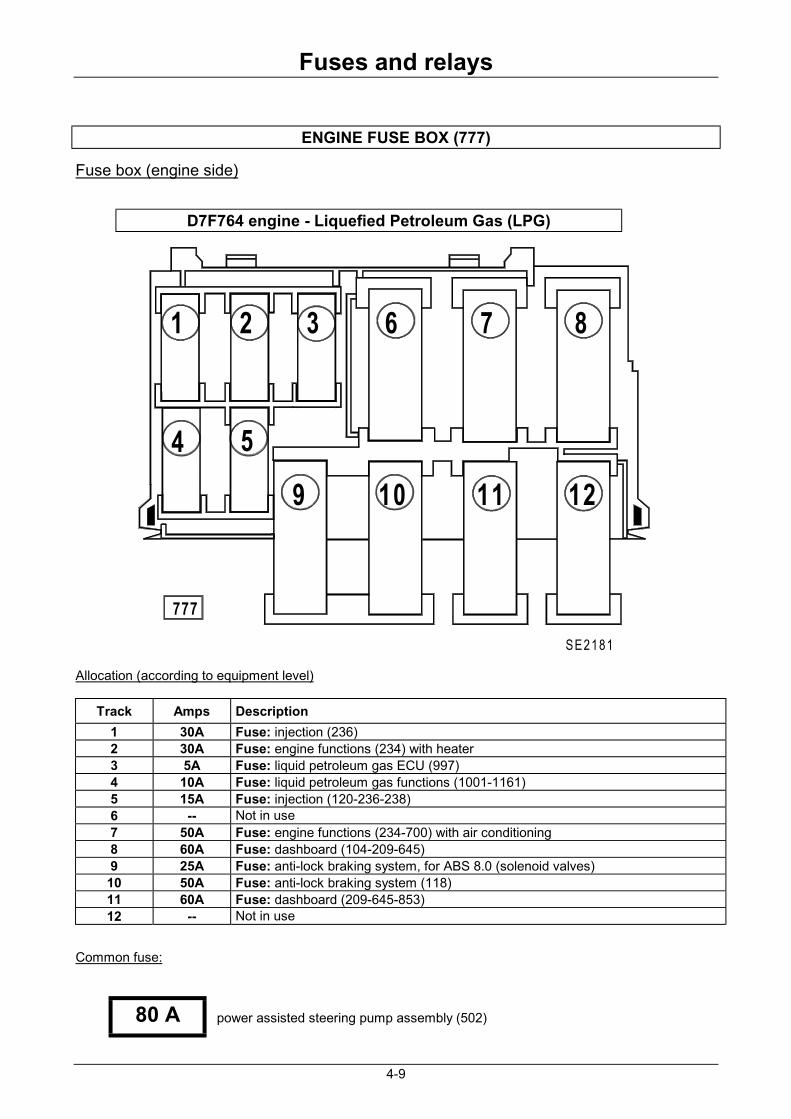
ENGINE FUSE BOX (777)
Fuse box (engine side)
4 5
9
777
10
1 2 63
SE2181
11 12
87
Allocation (according to equipment level)
Track Amps Description 1 30A Fuse: injection (236) 2 30A Fuse: engine functions (234) with heater 3 5A Fuse: liquid petroleum gas ECU (997) 4 10A Fuse: liquid petroleum gas functions (1001-1161) 5 15A Fuse: injection (120-236-238) 6 -- Not in use 7 50A Fuse: engine functions (234-700) with air conditioning 8 60A Fuse: dashboard (104-209-645) 9 25A Fuse: anti-lock braking system, for ABS 8.0 (solenoid valves) 10 50A Fuse: anti-lock braking system (118) 11 60A Fuse: dashboard (209-645-853) 12 -- Not in use
Common fuse:
power assisted steering pump assembly (502)
D7F764 engine - Liquefied Petroleum Gas (LPG)
80 A
Fuses and relays
4-10
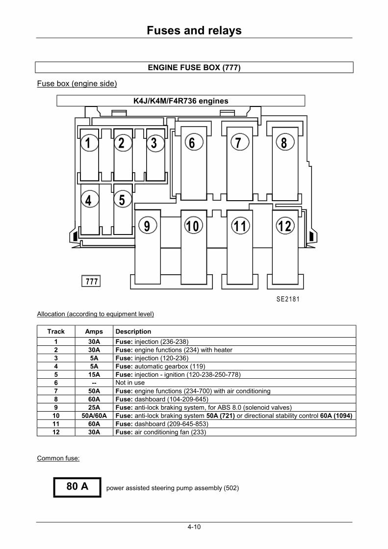
ENGINE FUSE BOX (777)
Fuse box (engine side)
4 5
9
777
10
1 2 63
SE2181
11 12
87
Allocation (according to equipment level)
Track Amps Description 1 30A Fuse: injection (236-238) 2 30A Fuse: engine functions (234) with heater 3 5A Fuse: injection (120-236) 4 5A Fuse: automatic gearbox (119) 5 15A Fuse: injection - ignition (120-238-250-778) 6 -- Not in use 7 50A Fuse: engine functions (234-700) with air conditioning 8 60A Fuse: dashboard (104-209-645) 9 25A Fuse: anti-lock braking system, for ABS 8.0 (solenoid valves) 10 50A/60A Fuse: anti-lock braking system 50A (721) or directional stability control 60A (1094) 11 60A Fuse: dashboard (209-645-853) 12 30A Fuse: air conditioning fan (233)
Common fuse:
power assisted steering pump assembly (502)
K4J/K4M/F4R736 engines
80 A
Fuses and relays
4-11
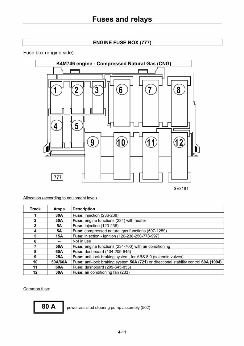
ENGINE FUSE BOX (777)
Fuse box (engine side)
4 5
9
777
10
1 2 63
SE2181
11 12
87
Allocation (according to equipment level)
Track Amps Description 1 30A Fuse: injection (236-238) 2 30A Fuse: engine functions (234) with heater 3 5A Fuse: injection (120-236) 4 5A Fuse: compressed natural gas functions (597-1259) 5 15A Fuse: injection - ignition (120-238-250-778-997) 6 -- Not in use 7 50A Fuse: engine functions (234-700) with air conditioning 8 60A Fuse: dashboard (104-209-645) 9 25A Fuse: anti-lock braking system, for ABS 8.0 (solenoid valves) 10 50A/60A Fuse: anti-lock braking system 50A (721) or directional stability control 60A (1094) 11 60A Fuse: dashboard (209-645-853) 12 30A Fuse: air conditioning fan (233)
Common fuse:
power assisted steering pump assembly (502)
K4M746 engine - Compressed Natural Gas (CNG)
80 A

Fuses and relays
4-12
ENGINE FUSE BOX (777)
Fuse box (engine side)
4 5
9
777
10
1 2 63
SE2181
11 12
87
Allocation (according to equipment level)
Track Amps Description 1 25A Fuse: injection (238) 2 30A Fuse: Engine functions (234) 3 -- Not in use 4 -- Not in use 5 15A Fuse: Engine functions (238-927) 6 70A Fuse: preheater unit (257-120) 7 50A Fuse: Engine functions (234-450-700) 8 60A Fuse: dashboard (104-209-645) 9 25A Fuse: anti-lock braking system, for ABS 8.0 (solenoid valves) 10 50A Fuse: anti-lock braking system (118) 11 60A Fuse: dashboard (209-645-853) 12 60A Fuse: air conditioning fan (233)
Common or dual fuse (according to equipment level):
power assisted steering pump assembly (502)
Thermoplungers (1049)
F9Q /K9K engines
80 A
80 A

Fuses and relays
4-13
ENGINE RELAY UNIT (597)
Relay unit (engine side)
J
597
E
GB D
SE2184
CA
Allocation (according to equipment level)
Track Amps Description A 60A Relay: fan unit (234) with air conditioning B 40A Relay: fuel pump (236) C 60A
40A Relay: sequential gearbox pump assembly (762) Relay: fan assembly (234) without air conditioning for F4R736
D 40A Relay: air conditioning compressor control (474) E 20A Relay: fan unit low speed (700) with air conditioning G 20A Relay: starter (232) J 20A Relay: injection locking (238)
Common or dual fuse (according to equipment level): Relay: cold air blower unit (233) (yellow) Relay: reversing light (602) (brown)
D4F/D7F/ K4J/K4M/ F4R engines except D7F 764
SE2109
SE2109

Fuses and relays
4-14
ENGINE RELAY UNIT (597)
Relay unit (engine side)
J
597
E
GB D
SE2184
CA
Allocation (according to equipment level)
Track Amps Description A 60A Relay: fan unit (234) with air conditioning B 40A Relay: fuel pump (236) C 60A Relay: sequential gearbox pump assembly (762) D 40A Relay: liquid petroleum gas solenoid valve (1161) E 20A Relay: fan unit low speed (700) with air conditioning G 20A Relay: starter (232) J 20A Relay: injection locking (238)
Relay (according to equipment): Relay: cold air blower unit (233) (yellow)
A - Relay: air conditioning compressor control (474) B - Relay: fuel pump cut-out for liquid petroleum gas (1196)
D7F764 engine - Liquefied Petroleum Gas (LPG)
A
S E 2 1 1 0
B

Fuses and relays
4-15
ENGINE RELAY UNIT (597)
Relay unit (engine side)
J
597
E
GB D
SE2184
CA
Allocation (according to equipment level)
Track Amps Description A 60A Relay: fan unit (234) with air conditioning B 40A Relay: fuel pump (236) C 50A Relay: compressed natural gas injection (597-1259) D 40A Relay: air conditioning compressor control (474) E 20A Relay: fan unit low speed (700) with air conditioning G 20A Relay: starter (232) J 20A Relay: injection locking (238)
Common or dual fuse (according to equipment level): Relay: cold air blower unit (233) (yellow)
A - Relay: fuel pump cut-out for compressed natural gas (1161-1196) B - Relay: compressed natural gas tank solenoid valve control (1161-1457)
K4M746 engine - Compressed Natural Gas (CNG)
SE2109
A
SE2110
B
Fuses and relays
4-16
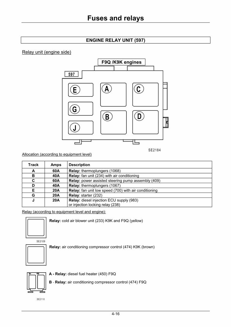
ENGINE RELAY UNIT (597)
Relay unit (engine side)
J
597
E
GB D
SE2184
CA
Allocation (according to equipment level)
Track Amps Description A 60A Relay: thermoplungers (1068) B 40A Relay: fan unit (234) with air conditioning C 60A Relay: power assisted steering pump assembly (409) D 40A Relay: thermoplungers (1067) E 20A Relay: fan unit low speed (700) with air conditioning G 20A Relay: starter (232) J 20A Relay: diesel injection ECU supply (983)
or injection locking relay (238)
Relay (according to equipment level and engine): Relay: cold air blower unit (233) K9K and F9Q (yellow) Relay: air conditioning compressor control (474) K9K (brown) A - Relay: diesel fuel heater (450) F9Q B - Relay: air conditioning compressor control (474) F9Q
F9Q /K9K engines
SE2109
A
S E 2 1 1 0
B