Fused Deposition Modeling: A Technology Evaluation · · 2003-10-17Fused Deposition Modeling: A...
12
Fused Deposition Modeling: A Technology Evaluation Selecting the best rapid prototyping process can be challenging. Without hands-on experience, uncovering both the strengths and weaknesses of a technology can be difficult. Yet, this knowledge is critical in selecting the right tool for the intended application. A previous white paper by Accelerated Technologies, Inc. 1 filled this knowledge gap, from a user perspective, for three technologies: Stereolithography (SLA ® ), Selective Laser Sintering (SLS ® ) and PolyJet. ™ To add to this body of information, another leading technology, fused deposition modeling (FDM ® ) is presented from the user’s point of view. When included in an evaluation, FDM can make selection even more difficult. This is true for two reasons. First, FDM brings forth a new set of evaluation criteria since the technology has a different parameter set than many of the other technologies. Second, while it is widely used, the technology is most often applied to internal 1 The paper is available at www.atirapid.com. use rather than service bureau operations, which limits the availability of hands-on data. To select the right process there are three areas of consideration: physical properties, operational constraints and intended applications. Each of these is addressed in this paper. With this information, a comparative analysis will lead to the selection of the best technology for the project. Process Overview Fused deposition modeling, developed and manufactured by Stratasys, Inc., is available in a number of systems. These include the FDM Maxum, ™ FDM Titan, ™ FDM3000 and Prodigy Plus. ™ FDM offers functional prototypes with ABS, polycarbonate and other materials. These thermoplastics are extruded as a semi-molten filament. This filament is deposited on a layer-by-layer basis to construct a prototype directly from 3D CAD data. The technology is commonly applied to form, fit and function analysis and concept visualization. Todd Grimm T. A. Grimm & Associates, Inc.
Transcript of Fused Deposition Modeling: A Technology Evaluation · · 2003-10-17Fused Deposition Modeling: A...

F u s e d D e p o s i t i o n M o d e l i n g : A T e c h n o l o g y E v a l u a t i o n
Selecting the best rapid prototyping process can be challenging. Without hands-on experience, uncovering both the strengths and weaknesses of a technology can be difficult. Yet, this knowledge is critical in selecting the right tool for the intended application.
A previous white paper by Accelerated Technologies, Inc.1 filled this knowledge gap, from a user perspective, for three technologies: Stereolithography (SLA®), Selective Laser Sintering (SLS®) and PolyJet.™ To add to this body of information, another leading technology, fused deposition modeling (FDM®) is presented from the user’s point of view.
When included in an evaluation, FDM can make selection even more difficult. This is true for two reasons. First, FDM brings forth a new set of evaluation criteria since the technology has a different parameter set than many of the other technologies. Second, while it is widely used, the technology is most often applied to internal 1 The paper is available at www.atirapid.com.
use rather than service bureau operations, which limits the availability of hands-on data.
To select the right process there are three areas of consideration: physical properties, operational constraints and intended applications. Each of these is addressed in this paper. With this information, a comparative analysis will lead to the selection of the best technology for the project.
Process Overview Fused deposition modeling, developed and manufactured by Stratasys, Inc., is available in a number of systems. These include the FDM Maxum,™ FDM Titan,™ FDM3000 and Prodigy Plus.™ FDM offers functional prototypes with ABS, polycarbonate and other materials. These thermoplastics are extruded as a semi-molten filament. This filament is deposited on a layer-by-layer basis to construct a prototype directly from 3D CAD data. The technology is commonly applied to form, fit and function analysis and concept visualization.
Todd GrimmT. A. Grimm & Associates, Inc.
Fused Deposition Modeling: A Technology Evaluation 2
Additionally, FDM can be applied to pattern generation and rapid manufacturing.
FDM Terms
WaterWorks:™ Soluble support structure dissolved in a water-based solution.
Break Away Support Structure (BASS™): Predecessor to WaterWorks that requires manual stripping of supports from the part surface.
Tip: Extrusion nozzle. Tips with various orifice sizes are user selected.
Road: Extrusion of material in a single pass of the tip. Controlled by tip size and feed rate of material.
Physical Properties Matching the physical requirements of the prototype’s application is perhaps the most important factor in selecting a rapid prototyping technology. The physical properties of the rapid prototype define its quality and determine success or failure in a given application.
Material Properties
When asked to rank areas of importance, rapid prototyping users often state that material properties are the most important consideration. To address the needs of industry, material properties that match those of the intended production material are important. And this is
one of FDM’s greatest strengths.
While Stratasys manufactures all of the materials for the FDM process, each is produced from a custom blend of commercially available thermoplastic resins.
ABS All systems in the FDM line-up offer ABS as a material option, and nearly 90 percent of all FDM prototypes are produced in this material. Users report that the ABS prototypes demonstrate between 60 and 80 percent of the strength of injection molded ABS. Other properties, such as thermal and chemical resistance, also approach or equal those of injection molded parts. This makes ABS a widely used material for functional applications.
Polycarbonate Use of a new rapid prototyping material available on the Titan, polycarbonate, is growing rapidly. The additional strength of polycarbonate produces a prototype that can withstand greater forces and loads than the ABS material. Some users believe that this material produces a prototype that demonstrates the strength characteristics of injection molded ABS.
Other materials While not as widely used as ABS, there are other specialty materials for FDM. These include polyphenylsulfone, elastomer and wax. Polyphenylsulfone, soon to be available on the

Fused Deposition Modeling: A Technology Evaluation 3
Titan, offers high heat and chemical resistance with strength and rigidity. The elastomer is intended for functional prototypes that behave like a “rubber” part with a durometer in the mid to upper range of the Shore A scale. The wax material is specifically designed for the creation of investment casting patterns. The properties of the wax allow the FDM pattern to be processed similar to the traditional wax patterns used in foundries.
Color Including white, which is the most frequently used color, ABS comes in eight material colors. The color options include blue, yellow, orange, red, green, black and gray. The medical grade ABSi offers translucency for applications such as automotive light lenses in clear, red or yellow.
Property stability Unlike SLA and PolyJet resins, the material properties of the FDM materials do not change with time or environmental exposure. Just like their injection molded counterparts, these materials retain their strength, toughness and color in nearly any environment.
Accuracy
The dimensional accuracy of a rapid prototype is dependent on many factors, and results can vary from part to part or day to day. Consideration must be given to issues such as the time frame in which measurements are
taken, axis to be measured, part benching and environmental exposure. Accuracy data for Maxum, Titan and Prodigy Plus is presented in Figure 2. The accuracy test part shown in Figure 1 was constructed in each machine (0.007 in. layers) to develop the presented accuracy data.
Part construction In general, FDM provides accuracies that are equal to or better than SLA and PolyJet and better than those of SLS. However, contradictory results may occur on individual prototypes since the accuracy is dependent on many factors.
FDM’s accuracy is affected by fewer variables. With SLA, SLS and PolyJet, the dimensional accuracy can be affected by factors that include machine calibration, operator skill, part orientation and location, age of material and proper application of shrink rates. Additionally, these other technologies often have to address issues of warpage and curling, an adverse effect of shrinkage and residual stress.
Z axis While not always the case, the Z axis may prove to be the least accurate. In addition to the variables previously discussed, the height of a prototype may be altered by round-off error. This is true of all rapid prototyping systems.
Should the topmost or bottommost surface of any feature not be aligned with that of a layer, the slicing algorithm in the preparation software

Fused Deposition Modeling: A Technology Evaluation 4
will round the dimension to the nearest full layer thickness. In the worst case, where one surface rounds down and the other up, the height could be off by one layer thickness. For typical FDM parameters, this could yield a maximum deviation of 0.012 in.
Stability Dimensional stability is a key advantage of FDM prototypes, as it is for SLS. Time and environmental exposure do not alter the size of the part or its features. Once a prototype is removed from the FDM system, and it reaches room temperature, the dimensions are fixed. To
varying degrees, this is not the case with SLA or PolyJet.
Post processing Many rapid prototyping processes require hand finishing for even the most basic levels of part quality. For example, SLA requires that support structures be manually removed from the part surface, which requires some hand sanding. This means that the accuracy of the part is no longer a function of only the system’s accuracy. It is now controlled by the skill level of the bench technician.
®
Figure 1: Illustration of the test part used for both dimensional accuracy and run time analysis. This part was constructed on the FDM Titan with 0.007 in. layers.

Fused Deposition Modeling: A Technology Evaluation 5
For form, fit and function prototypes, most users find that the surface finish of the FDM part is acceptable. This, when combined with WaterWorks, and to some extent, BASS, means that the accuracy of the FDM prototype is not altered by human hands.
Of course, if a mold-ready or paint-ready surface is required, the FDM parts will require benching, as do the other technologies. In this case, the skill of the part finisher plays a critical role in the deliverable accuracy of the prototype.
Surface Finish
The most obvious limitation of FDM, acknowledged by both users and Stratasys, is surface finish. Due to the extrusion of a semi-molten plastic, surfaces exhibit a rougher finish than SLA and PolyJet, and a finish that is comparable to SLS. While improved surface finish is possible with smaller road widths and thinner layers, the top, bottom and side walls will still show the contours of the passes of the extrusion tip and the build layers. Figure 3 lists the surface finish for the Maxum and Titan. To improve surface finish, both the Maxum and Titan now offer 0.005 in. layers.
FDM Maxum
FDM Titan Prodigy Plus
Nominal Actual Deviation % Actual Deviation % Actual Deviation %
A 3.000 3.000 0.000 0.00 3.000 0.000 0.00 2.995 0.005 0.17
B 1.000 1.003 0.003 0.30 1.004 0.004 0.40 1.006 0.006 0.60
C 6.000 6.000 0.000 0.00 5.995 0.005 0.08 6.000 0.000 0.00
D 0.100 0.099 0.001 1.00 0.100 0.000 0.00 0.100 0.000 0.00
E 3.000 2.998 0.002 0.07 2.995 0.005 0.17 2.997 0.003 0.10
F 4.000 3.999 0.001 0.02 3.993 0.007 0.18 3.996 0.004 0.10
G 1.000 1.003 0.003 0.30 1.004 0.004 0.40 1.006 0.006 0.60
H1 0.500 0.497 0.003 0.60 0.498 0.002 0.40 0.494 0.006 1.20
H2 0.500 0.497 0.003 0.60 0.499 0.001 0.20 0.494 0.006 1.20
I 0.500 0.499 0.001 0.20 0.500 0.000 0.00 0.497 0.003 0.60
J 0.250 0.253 0.003 1.20 0.258 0.008 3.20 0.255 0.005 2.00
K 0.500 0.499 0.001 0.20 0.503 0.003 0.60 0.503 0.003 0.60
Minimum 0.00 0.00 0.00
Maximum 1.20 3.20 2.00
Average 0.37 0.47 0.60
Figure 2: Dimensional accuracy data for the Maxum, Titan and Prodigy Plus. All test parts were constructed with 0.007 in. layers. All dimensions are listed in inches.

Fused Deposition Modeling: A Technology Evaluation 6
FDM Maxum Ra (µin.)
FDM Titan
Ra (µin.)
Top Surface
- Unfinished 550 475
- Light sanding 275 150
Side Wall
- Unfinished 450 425
- Light Sanding 200 175
Bottom Surface
- Unfinished 550 575
- Light Sanding 125 100
Figure 3: Surface finish data for the Maxum and Titan. All test parts constructed with 0.007 in. layers.
Users find it wise to consider surface finish requirements when orienting a part for building. Those surfaces that demand a higher level of finish are often oriented vertically. Surfaces of lesser importance are oriented horizontally such that they are either a bottom or top surface.
As with other technologies, secondary operations (post processing) can be used as an equalizer. However, the toughness of the ABS and polycarbonate materials makes sanding more laborious. Users often report that they utilize solvents or adhesives as a one step process or in preparation for sanding. Commercially available, these agents include Weld-On, ABS glue, Acetone and two-part epoxies. With enough finishing, FDM and the competitive processes can produce a mold-ready
or paint-ready surface. The key difference is how much time it will take to achieve the desired result.
Feature Definition
Although advanced operators of an FDM system can produce smaller features, most FDM prototypes are constrained to a minimum feature size that is twice the road width. Without user intervention, the FDM process uses a “closed path” that limits the minimum feature size to two passes of the extrusion tip.
For common tip sizes and build parameters, the minimum feature size ranges from 0.016 to 0.024 in. While larger than that of SLA and PolyJet, this range is in line with the useable minimum feature size of these technologies. Although SLA can build as small as 0.003 (Viper si2™) to 0.010 in. (all others), and PolyJet can build as small as 0.0015 in., few prototypes take advantage of this minimum for all but the smallest details. Considering material properties, it is common to find that both SLA and PolyJet prototypes use a minimum feature size of 0.020 in. FDM’s minimum feature size is equal to or better than that of SLS, which is 0.025 to 0.030 in.
With material properties similar to injection molded ABS or polycarbonate, FDM can deliver a functional feature size in the 0.016 to 0.024 in. range.

Fused Deposition Modeling: A Technology Evaluation 7
Environmental Resistance
FDM prototypes offer material properties similar to those of the base thermoplastic. This includes environmental and chemical exposure. With the ABS material, users can subject their prototypes to temperatures of 200° F and chemical agents that include oil, gas, and even some acids.
A key consideration is moisture exposure, both in terms of immersion and humidity. SLA and PolyJet use photopolymers that can be sensitive to moisture. Exposure to water or humidity will affect not only mechanical properties but also dimensional accuracy. As photopolymers absorb moisture, they will soften and become somewhat pliable. Also, the parts have a tendency to warp or swell, which can have a dramatic effect on accuracy. FDM prototypes, and those from SLS, are unaffected by moisture, so they retain their original mechanical properties and dimensional accuracy.
Machining
With little additional consideration, FDM prototypes can be milled, drilled, tapped and turned. To offset surface deficiencies and improve feature detail, users often perform a secondary machining operation to refine the details of the prototype when exceptional quality is necessary.
Operational Considerations After consideration of the physical properties of the prototype, attention should then be placed on operational parameters. The following areas can impact the use of the prototype for the intended application.
Part Size
Unlike the other technologies, the advertised size of the FDM build envelope is that of the maximum part size. With the family of systems, FDM offers a wide range of build envelopes. Maxum, the biggest, offers parts sizes up to 23.6 x 19.7 x 23.6 inches. This build envelope is on par with that of the largest SLA systems. Titan offers a maximum part size of 16 x 14 x 16 inches. This envelope is slightly larger than that of the SLS Sinterstations.® Prodigy Plus, the smallest, has an envelope of 8 x 8 x 12 inches, which is slightly smaller than both the PolyJet systems and the smallest SLA system.
As with the competitive technologies, prototypes that exceed the build envelope are often constructed in sections and later bonded. Using commercially available ABS adhesives, the bond strength on an FDM part is suitable even in functional applications. In addition, the FDM parts can be ultrasonically welded, an option that is unavailable in SLA and PolyJet since they do not use thermoplastics.

Fused Deposition Modeling: A Technology Evaluation 8
Support Structures
In FDM, a supporting structure is required to form a base to mount the part and to support any over hanging features. At the interface with the part, a solid layer of supporting material is laid down. Beneath this solid layer, roads with 0.020 in. and 0.150 in. gaps are deposited. FDM offers two styles of supports, break away support structures (BASS) and water-soluble support structures (WaterWorks.)
BASS supports are manually removed by stripping them from the part surface. While they do not mar the part surface, consideration must be given to accessibility and proximity to small features.
WaterWorks uses a soluble material that is dissolved in a water/solvent solution. Unlike BASS, the supports can be located in deeply recessed regions of the part, or in contact with small features, since mechanical removal is eliminated. As long as there is no requirement for surface enhancement, WaterWorks offers a prototype that eliminates the need for the labor that is required for the other technologies. In addition, WaterWorks preserves small features. In the other technologies, they pose a challenge to support removal without feature damage.
One-Piece Assembly
With the advent of WaterWorks, FDM offers a unique solution — building working assemblies in one piece. Since WaterWorks supports are dissolved, a multi-piece assembly can be
constructed in one machine run. While multi-piece assemblies are feasible in SLS and PolyJet, careful consideration must be given to the accessibility of the residual material between components. For example, the FDM brain gear shown in Figure 4 can be ready for operation with no manual labor and a few hours to dissolve the WaterWorks supports. This same part in SLS may take an hour or more of manual labor to remove powder from between the gears and shafts.
While it is beneficial to determine if and how parts can be assembled, early in the process it is more important to evaluate the design and functionality of the assembly. With
Figure 4: Brain gear built as a one-piece assembly using WaterWorks to eliminate manual support removal.
Fused Deposition Modeling: A Technology Evaluation 9
WaterWorks, the CAD data for the entire assembly can be processed as one part. Also, there is no labor or time required to tweak and assemble the parts to fit.
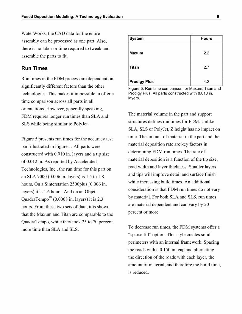
Run Times
Run times in the FDM process are dependent on significantly different factors than the other technologies. This makes it impossible to offer a time comparison across all parts in all orientations. However, generally speaking, FDM requires longer run times than SLA and SLS while being similar to PolyJet.
Figure 5 presents run times for the accuracy test part illustrated in Figure 1. All parts were constructed with 0.010 in. layers and a tip size of 0.012 in. As reported by Accelerated Technologies, Inc., the run time for this part on an SLA 7000 (0.006 in. layers) is 1.5 to 1.8 hours. On a Sinterstation 2500plus (0.006 in. layers) it is 1.6 hours. And on an Objet QuadraTempo™ (0.0008 in. layers) it is 2.3 hours. From these two sets of data, it is shown that the Maxum and Titan are comparable to the QuadraTempo, while they took 25 to 70 percent more time than SLA and SLS.
System Hours
Maxum 2.2
Titan 2.7
Prodigy Plus 4.2
Figure 5: Run time comparison for Maxum, Titan and Prodigy Plus. All parts constructed with 0.010 in. layers.
The material volume in the part and support structures defines run times for FDM. Unlike SLA, SLS or PolyJet, Z height has no impact on time. The amount of material in the part and the material deposition rate are key factors in determining FDM run times. The rate of material deposition is a function of the tip size, road width and layer thickness. Smaller layers and tips will improve detail and surface finish while increasing build times. An additional consideration is that FDM run times do not vary by material. For both SLA and SLS, run times are material dependent and can vary by 20 percent or more.
To decrease run times, the FDM systems offer a “sparse fill” option. This style creates solid perimeters with an internal framework. Spacing the roads with a 0.150 in. gap and alternating the direction of the roads with each layer, the amount of material, and therefore the build time, is reduced.

Fused Deposition Modeling: A Technology Evaluation 10
Since FDM runtime is unaffected by Z height, with the exception of any additional support material, orientation of the part for the best quality is possible without a time penalty. In each of the other technologies, there is often a trade-off between time and quality when an orientation with the lowest Z results in decreased build times but inferior feature quality.
A final consideration is that FDM does not require a significant amount of time to bring the system to operating temperature or to allow a completed part to cool. In the SLS process, the pre-build warm up and post-build cool down can add two to four hours for each run of the system.
Applications To select the best process for a given application, it is important to distinguish between needs and wants. Needs translate to requirements for success while wants correlate with desires and expectations that may not be necessary for a successful application. This distinction is made because many in the industry demand from the rapid prototype what is not necessary for success and in some cases that which cannot be reproduced in production.
With a clear understanding of the needs of the application, the information in the previous sections can be applied to the selection process.
Concept Models
Many FDM users treat the technology as a design peripheral. As such, the technology becomes another tool linked to and driven by the CAD system for the purpose of interrogating and validating design concepts early in the process. With such an application, FDM is used as a concept modeling tool that delivers clear communication of today’s increasingly sophisticated and complex designs.
While FDM may not offer the speed expected from a concept modeler, it offers a combination of benefits that make it a good choice for concept modeling and visualization applications. These strengths include accuracy, material properties, color and the elimination of manual part finishing. Although material strength and toughness may not be critical for a concept model, it is often desirable because a weak prototype is often broken at the most inopportune time.
FDM models are also applied to sales and marketing, both internally and externally. Internally, the FDM prototypes are used to give the sales team, management and other employees a first look at a product before it is released to manufacturing. Externally, the prototypes are used to excite and interest prospective customers well before the product’s commercial release.

Fused Deposition Modeling: A Technology Evaluation 11
Form, Fit & Function Models
With many technologies, the common application of rapid prototyping to form, fit and function analysis requires that some sacrifices be made. While technologies like SLA and PolyJet offer good detail, accuracy and surface finish, they may not deliver the necessary strength and toughness. Similarly, SLS offers strength while sacrificing accuracy and detail.
For FDM, this is a frequent application because it does not require the significant trade-offs of the other technologies. With the ABS and polycarbonate materials, FDM offers strong and tough prototypes with the detail, accuracy, and machinability required for functional analysis of molded plastic parts. Although an unfinished part may not have the surface finish of a production part, many do not find this to be an obstacle for this application. Additionally, surface finish is often secondary to other factors such as dimensional stability, heat resistance and chemical inertness.
Tooling Patterns
Rapid prototypes can be used as patterns for the creation of molds and tooling. And like other rapid prototyping technologies, FDM can be successfully used as a pattern generator. However, consideration must be given to the surface finish and the time required to bench a part to master pattern specifications.
Investment casting has an additional demand of its patterns. The patterns must be able to be burned out of the ceramic mold that they create. Both wax and ABS patterns constructed from the FDM process have proven to be suitable for burn out from the ceramic shell with minimal modification to the standard foundry processes.
Rapid Manufacturing
Rapid prototyping has fueled an interest in short run manufacturing where economic order quantities could be as small as a single unit. This application requires that the part meet functional specifications in many areas. With the accuracy and material properties available from FDM, it is one of the few technologies positioned to address this application.
While an unfinished FDM part would have limited use in visible, cosmetic applications, it is not an obstacle for internal components or those that do not require aesthetic appeal. For rapid manufacturing applications, run times would also be an important consideration. Yet, as several users have proven, the run times for a few parts are significantly less that the total time required to produce tooling and parts.

Fused Deposition Modeling: A Technology Evaluation 12
Conclusion Securing information on both the strengths and weaknesses of rapid prototyping technologies is the first step to making a wise decision. Although the information presented is thorough, it cannot encompass all that is required for every application. So, the next step is to evaluate the necessary requirements for the application and continue to acquire information from other sources. And remember, no technology is right for every situation. You must choose the best tool for the task at hand.
© 2002 T. A. Grimm & Associates, Inc. All Rights Reserved.
3D Systems, SLA, SLS, and Sinterstation are registered trademarks of 3D Systems, Inc. PolyJet and QuadraTempo are trademarks of Object Geometries.
Stratasys and FDM are registered trademarks and Titan, Maxum, Prodigy Plus; WaterWorks and BASS are trademarks of Stratasys, Inc. All others are property of their respective owners.
For More Information on Stratasys: 1-888-480-3548 www.stratasys.com [email protected]
Todd GrimmT. A. Grimm & Associates, Inc.
Todd Grimm, president of T. A. Grimm & Associates, Inc., has been actively involved in the rapid prototyping industry since 1990. After five years in the CAD industry, Todd began working with rapid prototyping service bureaus and has had responsibility for general management, sales and marketing. He is recognized as an accomplished speaker and author on rapid prototyping. With Terry Wohlers, president of Wohlers Associates, Todd co-authors a monthly feature in the industry trade publication Time-Compression Technologies. For the past four years, Todd has served as an advisor for the Society of Manufacturing Engineers’ Rapid Prototyping & Manufacturing conference and tradeshow. He is a graduate of Purdue University where he earned a Bachelor of Science degree in Mechanical Engineering.