Fuse Caps, Blocks, Clips, Holders, Mountings, Panels, and ... · not be used on fuse caps that are...
16
BEU SYSTEM PRAOICES SECTION 026-370-801 AT& TCo Standard Issue 8, April 1983 • FUSE CAPS, BLOCKS, CLIPS, HOLDERS, MOUNTINGS, PANELS, AND POSTS REPAIR AND REPLACEMENT PROCEDURES • CONTENTS PAGE CONTENTS PAGE 1. GENERAL 9. Tooth in Locked Position 9 j 2. APPARATUS 10. Spring Stretched 9 3. REPLAaMENT PROCEDURES 11. P.344900 . Fuse Caps 10 • A. Fuse Caps f« Nonindicating.Type Fuses 12. KS.14170 Fuse Biock 10 13. KS.14473 Fuse Block 10 B. Fuse Caps f« 7().. Type Fuses 14. KS.16364 Fuse Bk,ck 10 c. Neoprene Washers for fuse Caps for 70- Type Fuses 15. KS.19393, l22, fuse Block 11 D. Insertion and Removal of P·11f667 fuse 16. 20A Fuse Bfock Mounting Methods 11 Cap Using 821A Insertion Tool 17. 20A fuse Block (Head Mounting Using 64A E. Fuse Blocks 6 Bracket) 11 • ,. Fuse Clips 12 18. KS.20521 Typical Mounting Arrangement 12 G. Fuse Holders, Mountings, Panels, and Posts 13 19. KS.21613, Ll, Fuse Clip (Battery Terminal) 13 figures 20. KS.21613, l2, fuse Clip (Load Terminal) 1. KS.14169 fuse Block 13 2. P•21E517 and P·12F160 Fuse Caps 21 . KS.21613, l3, fuse Clip (Alarm Terminal) 13 3 . P· 11 F667 and P.344900 Fuse Caps • 22. KS.5842 Fuse Holder 14 4. Identification of Old and New Design Fuse Bloclc Covers 6 23. KS.15715 Fuse Holder 15 5. 8208 Tool 24. KS.15858 Fuse Mounting 15 6. 958A fuse Block Repair Tool 25. KS.19392, l2, Fuse Panel 15 • 7. Fuse Panel 26 • KS.5083 Fuse Post 16 8. Tool Insertion Into Spring Tang 27 . KS.14473, l4, fuse Holder Puller Tool 16 • NOTICE Not for use or disclosure outside the Bell System except under written agreement Printed in U.S.A. Page 1 downloaded from: TCI Library - http://www.telephonecollectors.info - Source: Connections Museum, Seattle, WA
Transcript of Fuse Caps, Blocks, Clips, Holders, Mountings, Panels, and ... · not be used on fuse caps that are...
BEU SYSTEM PRAOICES SECTION 026-370-801 AT& TCo Standard Issue 8, April 1983
• FUSE CAPS, BLOCKS, CLIPS, HOLDERS, MOUNTINGS, PANELS, AND POSTS
REPAIR AND REPLACEMENT PROCEDURES
• CONTENTS PAGE CONTENTS PAGE
1. GENERAL 9. Tooth in Locked Position 9
j 2. APPARATUS 10. Spring Stretched 9
3. REPLAaMENT PROCEDURES 11. P.344900 . Fuse Caps 10 • A. Fuse Caps f« Nonindicating.Type Fuses 12. KS.14170 Fuse Biock 10
13. KS.14473 Fuse Block 10 B. Fuse Caps f« 7().. Type Fuses
14. KS.16364 Fuse Bk,ck 10 c. Neoprene Washers for fuse Caps for 70-
Type Fuses 15. KS.19393, l22, fuse Block 11
D. Insertion and Removal of P·11f667 fuse 16. 20A Fuse Bfock Mounting Methods 11 Cap Using 821A Insertion Tool
17. 20A fuse Block (Head Mounting Using 64A E. Fuse Blocks 6 Bracket) 11 • ,. Fuse Clips 12 18. KS.20521 Typical Mounting Arrangement
12 G. Fuse Holders, Mountings, Panels, and
Posts 13 19. KS.21613, Ll, Fuse Clip (Battery Terminal) 13
figures 20. KS.21613, l2, fuse Clip (Load Terminal)
1. KS.14169 fuse Block 13
2. P•21E517 and P·12F160 Fuse Caps 21 . KS.21613, l3, fuse Clip (Alarm Terminal) 13
3 . P· 11 F667 and P.344900 Fuse Caps • 22. KS.5842 Fuse Holder 14 4. Identification of Old and New Design Fuse
Bloclc Covers 6 23. KS.15715 Fuse Holder 15
5. 8208 Tool 24. KS.15858 Fuse Mounting 15
6. 958A fuse Block Repair Tool 25. KS.19392, l2, Fuse Panel 15
• 7. Fuse Panel 26 • KS.5083 Fuse Post 16
8. Tool Insertion Into Spring Tang 27 . KS.14473, l4, fuse Holder Puller Tool 16
• NOTICE Not for use or disclosure outside the
Bell System except under written agreement
Printed in U.S.A. Page 1 downloaded from: TCI Library - http://www.telephonecollectors.info - Source: Connections Museum, Seattle, WA

SECTION 026-370.801
CONTENTS PAGE 1.04 DANGER: For link-type fuses, covers
Tabte are to be left ia place when DO service is
being performed. A fuse upon failing, particularly the link-type where the fuse metal is
A. KS-20521 Fuse Oips 12 unprotected, usually becomes molten metal instantly and, if spattered, may cause serious la.jury to a person nearby.
1. GENERAL
1.01 This section provides the information necessary for repairing and replacing the following
fuse caps, blocks, clips, holders, mountings, panels, and posts used in telephone power plants:
9A 12 Type 13A 14A 15 Type 18 Type 19A 20A
21A 22 Type 23 Type 24 Type 25 Type 26A 27A 29A
30 Type 31 Type 34 Type KS-14169 KS-14170 KS-14473 KS-16364 KS-19393
1.02 Revision arrows are used to emphasize significant changes. The Equipment Test List is not
affected. The reasons for reissue are listed below.
(a) To change the title
(b) To add information on the replacement of the 20A fuse bl0<k
(c) To rate the 820A tool Mfr Disc. and replaced by the 820B tool
(d) To add a note on the KS-14169 fuse block
(e) To add a note on link-type fuses.
1.03 DANGER: Extreme care must be takea whea working oa or aear equipment
with high current capability aad/or whea high voltage is present. To prevent bodily i.a.jury, bracelets, ri.a.gs, key chains, wrist watches, metal belts, aad buckles should aot be wora while iaspectiag or maiataiaiag electrical equipment. Iasulated tools (see Section 074-000-001), gloves, aad mats should be used at all times. However; it is aot necessary to use aa insulated mat whea working oa de distributing boards which do aot exceed 135 volts.
Page 2
l.05 DANGER: Whea it is aot possible to remove potential from the fuse, clips, or
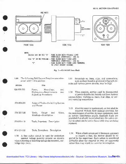
curreat•carryiag coaaectioas of high-voltage/ current circuits, the adjacent clips or coaaec• tioas of opposite polarity shall be wrapped with canvas or friction tape to prevent accidental contact which might result iD a short circuit or injury to the person. Terminals that are spring loaded aad must be free to move to generate contact pressure (terminals such as the load terminals oa fuse block KS-14169) should aot be taped. Tbe contact that is made through the movable terminal may be broken during the application or removal of the tape causing a service iaterruptioa. (See Fig. l tor terminal identification.)
1.06 DANGER: Uaiasulated metal tools, such as pliers, screwdrivers, aad
wrenches used for working oa or aear highvoltage/curreat circuits, should be iasulated with three wrappings of friction tape, each wrapping applied with a bait lap. If access to a aut or bolt is difficult and safety coaditioas warrant, the use of a box-ead wreacb may be advisable.
1.07 Caution: lt is recommended that work on live equipment be performed during
periods of light traffic. Each exception, in• eluding the temperature test of discharge fuses or removal of defective fuses, should be discussed with the supervisor before work is started since the removal of evea aa apparently mi.Dor fuse may result iD a service interruption.
1.08 Waraiog: A fuse cap coataiaiag a fuse should aot be removed from a "live" cir•
cuit for the purpose of de-energizing the equipment which the fuse is protecting. Acci• dental bumping of fuse caps i.a "live" circuits should also be avoided. Either of these occurrences can cause arcing of the curreatcarryi.ag coaaectioas, aad thus shorten fuse block lite.
• • •
•
• • •
downloaded from: TCI Library - http://www.telephonecollectors.info - Source: Connections Museum, Seattle, WA
• • •
•
• • •
ISS 8, SECTION 026-370-801
SEE NOTE
FRONT VIEW SIOE VIEW REAR VIEW
NOTE: RAISED OOT OR REO "X" - FUSE BLOCK WITH PIOVABLE LOAD
TERPIINALS (TERPIINALS 1 AND 2) RED "S" OR ND l'IARKING - FUSE BLOCK WITH FIXED LOAD
TERMINALS ( TERPIINALS 1 AMJ 2) "F" - FUSE BLOCK WITH FIXED LOAD TERPIINAL
IS (PllST RECENT DESIGN)
Fig. 1-KS-14169 Fuse Block
1.09 The following Bell System Practices are referenced within this section:
SECTION
026-370-701
074-000-001
074-220-125
074-226-119
074-257-133
'""' Fuses, Mountings, and Enclosures-Requirements and Adjusting Procedures
Index of Tools-Switching System and Power
Tools, Gauge and Glass, Reading-Description
Tools, Inserters-Description
Tools, Stretchers-Description
1.10 A fuse puller should be used for protection against voltage possibly present on circuits
when removing or inserting spring clip mounted, cartridge-type fuses .
1.11 Potentials on fuses, clips, and connections, such as those found in grounded telegraph cir
cuits and various power circuits, may be high.
1.12 When possible, service shall be disconnected at power distribution boards and from battery
sources before working on fuses, fuse clips, or current-carrying connections.
1.13 If service must be maintained, no fuse shall be removed with out first making provision for
the maintenance of service. In some equipment, such as battery distribution panels, duplicate fuses are provided that should be switched into the active circuit to substitute for active fuses while they are being replaced.
1.14 When a fault occurs and it becomes necessary to remove a fuse, the matter should be re
ported to the supervisor. Such action is considered advisable since the removal or even an apparently minor fuse may result in a service interruption.
Page 3 downloaded from: TCI Library - http://www.telephonecollectors.info - Source: Connections Museum, Seattle, WA

SEOION 026-370-801
2. APPARATUS EQUIPMENT DESCRIPTION
2.01 List of Tools, Materials, and Equipment: KS-14510, Ll The following tools, materials, and equipment
Volt-Ohm Milliammeter or Digital Type
are used in this section:
TOOlS
34-001
34-002
34-003
AT-7825
417A
418A
DESCRIPTION
Fuse Puller, Midget, Ideal Industries, Inc. (or equivalent)
Fuse Puller, 7-1/2 Inches, Ideal Industries, Inc. (or equivalent)
Fuse Puller, 12 inches, Ideal Industries, Inc. (or equivalent)
Soldering Iron.
3. REPLACEMENT PROCEDURES
3.01 After replacement of parts, the replacing parts shall meet the requirements specified in
Section 026-370-701.
A. Fus• Caps for Nonindicating-Type fuses
5-inch, E Screwdriver 3.02 It is recommended that a "two dot" fuse cap (Fig. 2) be substituted for the"one dot"(center
1/4-Inch and 3/8-Inch Open Dou- dot only) fuse cap on the •20A• nonmodular fuse hie-End Flat Wrench block and the 22B, 23B, 25A, 26A, and '!:lA modular
fuse blocks where trouble has been encountered or 5/16-Inch and 7/32-Inch Open heating is evident. Double-End Flat Wrench
t820B Tool•
821A
958A
KS-14473, IA
R-2512
MATERIALS
KS-20521
KS-21613
P-12Fl60
P-21E517
P-2!E546
Page 4
Insertion Tool
Fuse Block Repair Tool
Fuse Holder Puller Tool
Adjustable Wrench
Canvas or Tape
Fuse Clip (see Table A)
Fuse Clip (see Fig. 16, 17, and 18)
Fuse Cap (see Fig. 2)
Fuse Cap (see Fig. 2)
Neoprene Washer
Solder
SPHt:ltlCAL ltAlstO COT IOENTIFltS FUSE .,,, ......, .. "'""'''- ...... RICAL RAlstD DOT IDENTIFIES
CAP WITH STEEL SPRING
P-21E517 FUSE CAP (FOR 20A NON-MDDUL.AR FUSE BL.OCII:}
SPI-ER!CAL. RAISED OO'T IDENTIFIES FUSE CAP WITH IMPMIVED TERMINAL DESIGN
P-12Fl60 FUSE CAP ( FOR 228·, 238·,~A-, 26A-, 27.t.-, ANO 30-TYPE MODULAR FUSE BLOCKS)
fig. 2-P-2IE5l7 and P-12f160 fuse Caps
• • •
•
• • •
downloaded from: TCI Library - http://www.telephonecollectors.info - Source: Connections Museum, Seattle, WA

• • •
•
• • •
3.03 To replace the old fuse cap, fully depress the cap, rotate approximately one-fourth turn
counterclockwise, and remove the cap from the block. Insert and fully depress the new cap in the fuse block and turn approximately one-fourth turn clockwise. The latest design fuse cap, P-12Fl60or P-21E517, can be identified by two raised dots and by the color of the spring. Fuse caps of the modular- and nonmod ular-type fuse blocks are not interchangeable. No attempt should be made to replace the spring.
B. Fuse Caps fo, 70-Type Fuses
3.04 DANGER: The P-11F667 fuse caps were intended for use with modular
blocks and not with the KS-14169 blocks. The P11F667 caps will function electrically with the KS-14169 blocks, but do not completely shield the battery and alarm terminal slots. During violent fuse operation, these openings could act as vents for hot gases resulting in potential serious injury to personnel within 6 inches of the panel. When removing or replacing a fuse cap (Fig. 3) containing a 70-type fuse, the fuse cap must be depressed fully before attempting to rotate approximately one-fourth turn into or out of position. Failure to follow this procedure on the new design 18- through 24-type fuse blocks (Fig. 4) could result in bending of the battery terminal.
C. Neoprene Washen for Fuse Caps for 70-Type Fuses
3.05 The neoprene washer should not be used on fuse caps that are used on the. 18-, 19-, or 21-
type nonmodular fuse blocks. In addition, it should not be used on fuse caps that are used on new design 22-, 23-, and 24-type modular fuse blocks. These blocks have been redesigned and do not require the neoprene washer on the fuse cap. The use of the washer with the new design 22-, 23-, and 24-type blocks will prevent the fuse cap from being fully depressed. Hence, when the fuse cap is rotated into position, the battery terminal will probably be bent. In order to identify the new production ~2-, 23-, and 24-type fuse blocks (Fig. 4), circular mounting screw holes are used on the new design fuse block cover whereas rectangular holes are used on the old design. Neoprene washers should only be added to fuse caps now in the field where interruptions to the battery supply have been experienced due to a slight movement to the fuse cap on old design 22-, 23-, and 24-type modular blocks and all 25-, 26-, and 27-type modular blocks.
ISS 8, SECTION 026-370-801
D. Insertion and Removal of P-11 F667 Fuse Cap Using 821A Insertion Tool
3.06 The 821A insertion tool has been designed and produced to reduce the manual effort required
to insert and remove the P-11F667 fuse cap (Fig. 3), used in modular-type fuse blocks, when equipped with the neoprene washer.
(a} To remove the fuse cap, proceed as follows:
(1) Locate the 821A inserter tool over the fuse cap, and push in slightly.
(2) Rotate the tool counterclockwise to its maximum position.
(3) Retract the 821A insertion tool.
(b) Ti;> insert the fuse cap, proceed as follows:
(1) Locate the 821A insertion tool over the end of the cap.
P-11F667 FUSE CAP
!FIii PIDJI.NI FUSE 8Loac:S TYPE NO. 22, 23. 24. 25, 26. 27, 00 29)
P-344900 FUSE CAP
!f(IIMJII..IID.I.ARFUSE8LOCKSTYPEN0.18.1921KS-14169. KS-14170.KS-14473,AMIKS-16384)
Fig. 3-P-11F667 and P-344900 Fuse Caps
Page 5 downloaded from: TCI Library - http://www.telephonecollectors.info - Source: Connections Museum, Seattle, WA

SECTION 026--370-801
RECTANGULAR MOUNTING SCREW HOLES USED ON OLD DESIGN FUSE BLOCK COVERS
CIRCULAR MOUNTING SCREW HOLES US EDON NEW DESIGN FUSE BLOCK COVERS
Fig. 4-ldentffication of Old and New o.,ign FuMJ Block Coven;
(2) Push in, without rotating, until the neo-prene washer is slightly compressed be
tween the face of the fuse block and the flange of the fuse cap.
(3) Rotate . the tool clockwise to its maximum positio~.
(4) Retract the 821A insertion tool.
Note: See Section 074-226-119 for a description of the 821A insertion tool.
Page 6
E. Fuse lMoclcs
3.07 Silent Failures: Caution: While main-taining equipment which contains KS-
14169 fuse blocks, care must be taken to avoid creating silent failures (failures with no alarm) by moving individual wires or cables containing wires connected to spring loaded movable load terminals of the KS-14169 fuse block. (See Fig. 1.) Terminals 1 and 2 in the rear view are load terminals.
• • •
•
• • •
downloaded from: TCI Library - http://www.telephonecollectors.info - Source: Connections Museum, Seattle, WA

• • •
•
• • •
After the maintenance work is completed, check to insure that continuity bas been maintained in the circuits served by the KS-14169 fuse blocks, in and adjacent to the area, where the work was performed. Silent failures (failure with no alarm) have generally occurred in KS-14169 fuse block installations where one or a combination of the conditions listed below exists or did exist.
•Note: The latest design of the KS-14169 fuse blocks provides fixed terminals to eliminate silent failures.t
(1) Slack loops are inadequate.
(2) Heavy wire (14 gauge or larger) has been soldered directly to the load terminals.
(3) Load terminal leads are tied in a cable so that cable movement is transferred to the movable
load terminals.
(4) Leads have been soldered to the load terminals without removing a dummy fuse (72-type fuse)
before soldering. This causes partial melting of the dummy fuse and a subsequent loss of clearance necessary for functioning of the movable load spring-loaded terminals.
(5) Tape had been used to insulate terminals while working on adjacent apparatus. Either
during tape application or tape removal, forces were applied to the movable, spring-loaded load terminal causing a loss of contact between the terminal and the fuse. (See paragraph 1.05.)
3.08 tSpring Resilience: To check the spring resilience of the 18-, 19-, 21- through 27-, 29-,
30B-, and 30O-type fuse blocks, proceed as follows:t
(1) Either place necessary jumpers across fuse line to continue service or check while service
is disconnected.
(2) Remove the fuse cap from the position to be checked.
(3) Insert the •820B41 tool with the tool flat (Fig. 5) positioned so that the tool clears the block
designation pin (colored dot on the block).
155 8, SECTION 026-370-801
(4) If surface A of the •820841 tool (Fig. 5) contacts the fuse block before any force is felt against
the spring, the spring is considered unsatisfactory. The spring is satisfactory if there is a gap, no matter how small, between the fuse block face and surface A, when the tool makes contact with the spring.
SURFACE A ~-------. .______________q'u"
tFig. 5-820B Toolt
Note: See Section 07 4-220-125 for description of the t820Bt tool.
3.09 Spring Extension Repair: To stretch the spring of the 18-, 19-, or 21-type fuse blocks, or
similar internal springs of modular fuse blocks (22-through 27-, 29-, 30B-, and 30D-type fuse blocks), using the 958A fuse block repair tool (Fig. 6), proceed as follows:
(1) Either place necessary jumpers across fuse line to continue service or repair while service
is disconnected .
(2) Remove fuse cap and fuse.
(3) Visually locate the position of the spring tang (Fig. 7) in the fuse block. Use a portable light
if necessary.
(4) Insert the tool into the block until the spring enters the slot of the stationary shaft of tool.
(See Fig. 8.)
(5) While applying a slight inward pressure on the tool, rotate the knurled wheel clockwise
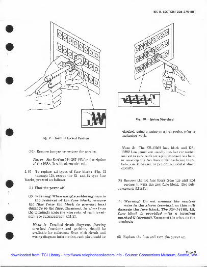
until it stops. This process engages the tooth into the first helix of the spring (Fig. 9).
Page 7 downloaded from: TCI Library - http://www.telephonecollectors.info - Source: Connections Museum, Seattle, WA

SECTION 026-370-801
Fig. 6-958A Fuse Block Repair Tool
~~~ 2A-4'- 1/2A ' 3
J~,:~ -4--C~~R\_ __ P_l_,l~----+-- ~NG
tirtiJ~ Fig. 7-Fuse Panel
Poge 8
Fig. I-Tool Insertion Into Spring Tang
(6) Squeeze the handles until the movable handle contacts the stop of the stationary handle.
This process stretches the spring between the sleeve and the end of the stationary shaft as shown in Fig.10.
(7) Release the handle and rotate the knurled wheel counterclockwise at least one-half of a
tum to disengage the tooth of the sleeve from the spring.
(8) Remove the tool from the fuse block.
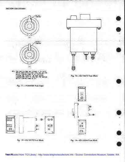
(9) Warning: The fuse cap used after spr~ng stretching must be per latest design
with the wide battery terminal [See J:ig . ll(a).J A fuse cap with a narrow battery terminal [Fig. ll(b)J should not be used after a spring is stretched. Replace fuse and fuse cap.
• • •
•
• • •
downloaded from: TCI Library - http://www.telephonecollectors.info - Source: Connections Museum, Seattle, WA
• • •
•
• • •
fig. 9-Tooth in Locked Position
(10) Remove jumper or restore the service.
Note: See Section 074-257-133 for description of the 958A fuse block repair tool.
3.10 To replace all types of fuse blocks (Fig. 12 through 15), except the 31- and 34-type fuse
blocks, proceed as follows:
(1) Shut the power off.
(2) Warning: When using a soldering iron in the removal of the fuse bloc~ remove
the fuse from the block to prevent heat damage to the fuse. Disconnect the wires from the terminals (note the wire color of each terminal). See subparagraph 3.11(2).
Note 1: Detailed circuit diagrams, showing terminal functions and position, should be available for reference. Even with circuit and wiring diagram information, each pin should be
ISS 8, SECTION 02~70-801
Fig. JO-Spring Stretched
checked, using a meter on a test probe, prior to initiating work.
Note 2: The KS-19393 fuse block and KS-19392 fuse panel are usually bus bar connected and extra care, such as taping exposed bus bars or covering the bus bars with insulating blankets, should be used to prevent accidental short circuits.
(3) Remove the old fuse block from the unit and replace it with the new fuse block. [See sub
paragraph 3.11(5).]
(4) Warning: Do not connect the neutral wire to the alarm terminal, as this will
damage the fuse block. The KS-14169, L3, fuse block is provided with a terminal marked G (ground). Reconnect the wires on the terminals.
(5) Replace the fuse and turn the power on.
Page 9 downloaded from: TCI Library - http://www.telephonecollectors.info - Source: Connections Museum, Seattle, WA
SECTION 026-370-801
<•>
Fig. 11-P4344 900 Fuse Caps
Fig. 12-KS-141 70 Fuse Btoc:k
Page 10
Fig. 13-KS-l 4473 Fuse Block
r□, ~ n
Fig. 14-KS-16364 Fuse Block
• • •
downloaded from: TCI Library - http://www.telephonecollectors.info - Source: Connections Museum, Seattle, WA

• • •
•
• • •
1: 0~ i,:1 FRONT VIEW
TOP VIEW SIDE VIEW
Fig. 15-KS-19393, L22, Fuse Block
3.11 ♦To replace the 20A fuse block, proceed as fol• lows:
(1) Shut the power off.
(2) Remove the lead from the battery terminal by holding inner hex nut with a wrench while
loosening the outer nut.
(3) Remove the lead from the load terminal. [See subparagraph 3.10 (2).]
(4) Remove the fuse block from the mounting pan· el.
Note 1: The 20A fuse block may either be head mounted or rear mounted (Fig. 16). The rear mounting is the preferred method for rea• son of strength and maximum voltage rating.
Note 2: If head mounting is necessary, 20A fuse block breakage can be alleviated by using the 64A bracket (a phosphor bronze bracket designed specifically for use with the 20A fuse block). (See Fig.17.)
ISS 8, SECTION 026-370-801
Il l
(a)IIEARIIOUNTING
111
tb)H£.I.OIIOUNTING
♦ Fig . 16-20A Fuse Btock Mounting Methodst
"'IIOUIHINGPANEL
tFig. 17-20A Fuse Block (Head Mounting Using 64A Bradc.et)t
Page 11 downloaded from: TCI Library - http://www.telephonecollectors.info - Source: Connections Museum, Seattle, WA

SECTION 026-370-801
Note 3: Where large leads are likely to exert loads which stress the fuse block, consideration should be given to the use of modular-type fuse blocks which have much greater strength.
(5) Warning: Regardless of whether the 20A fuse block is head mounted or rear mounted, leads should be performed prior to termination to minimize stress on the fuse block. The only acceptable method for securing the connection to the battery terminal is to hold one nut with a wrench while tightening the other nut with a second wrench to avoid imparting torque to other parts of the fuse block. Care must be taken to avoid applying side loads to the terminal during this operation.t
3. 12 To replace the 31- or 34-type fuse block, proceed as follows:
(1) Shut the power off.
(2) Remove the solder from around the pins on the printed circuit board.
(3) Remove the fuse block from the printed circuit board.
(4) Replace with new fuse block and reSOlder the pins.
(5) Turn pow_er on.
F. Fuse Clips
3.13 The KS-20521 fuse clips are used with car-tridge, ferrule-type fuses and supersede the P-
49472, P-65287, P-65288, and P-65289 fuse clips. Table A lists the KS-20521 fuse clips used with the specified ampere- and voltage-rated cartridge fuses.
3.14 To replace the KS-20521 fuse clip, remove the old clip from the base. Substitute the new fuse
clip, and replace as shown in Fig. 18.
Poge 12
TABLE A
KS-20521 FUSE OIPS
FUSE RATING RJSE QJP PART NO.
KS-20521, LI
KS-20521 , L2
KS-20521, L3
0-30.1.-10/32 31-a<lA-1/4X20
"-" SECUJtlNI NI.IT
AMPEtES VOLTS
= 250
31-60 250
()-30 250
INSULATION
=:::::R·:.e::::::~:;::::~::i:==:i.-.. IPALNUT
0-30.1. #10 RHW,COPPER 31-60.1. ••
F'tg. 18-KS-20521 Typical Mounting Am1ngement
3.15 The KS-21613 fuse clips are used with low-voltage 70-type fuses. The fuse clips are
mounted on printed circuit boards. The KS-21613, Ll, (Fig. 19) is a battery terminal. The KS-21613, L2, (Fig. 20) is the load terminal, and the KS-21613, L3, (Fig. 21) is the alarm terminal.
3.16 To replace the fuse clip, proceed as follows:
(1) Shut the power off.
(2) Remove the solder from the terminals of the fuse clip.
(3) Replace with new fuse clips and resolder.
(4) Turn power on.
• • •
•
• • •
downloaded from: TCI Library - http://www.telephonecollectors.info - Source: Connections Museum, Seattle, WA

• •
---- .....
• □
-
F'9. 19-KS-21613, Ll, Fuse Clip (Battery Terminal)
•
• • [] -
I
• Fig. 20-KS.21613, L2, Fu1e Clip (Load Terminal)
15S 8, SECTION 026.370-801
r" I I I I I
I I
Fig. 21-KS.21613, L3, Fu1e Clip (Alarm Terminal)
G. Fuse Holders, Mountings, Panels, and Posts
3.17 To replace all fuse holders (except KS•l4170, KS•l4473, and KS·16364), fuse mountings,
fuse panels, and fuse posts (Fig. 22 through 26), pro• ceed as follows:
(1) Shut the power off.
(2) Warning: When using a soldering iron in the removal of the unit, remove the fuse
to prevent heat damage to the fuse. Discon• nect the wires from the terminals (note the wire color on each terminal).
Note 1: Detailed circuit diagrams, showing terminal functions and position, should be available for reference. Even with circuit and wiring diagram information, each pin should be checked, using a meter on a test probe, prior to initiating work.
Note 2: The KS·19393 fuse block and KS-19392 fuse panel are usually bus bar connected and extra care, such as taping exposed bus bars
Page 13 downloaded from: TCI Library - http://www.telephonecollectors.info - Source: Connections Museum, Seattle, WA

SECTION 026-370-801
or covering the bus bars with insulating blankets, should be used to prevent accidental short circuits.
(3) Remove the old unit from the system. Replace it with the new unit.
(4) Reconnect the wires or bus bar on the terminals.
(5) Replace the fuse and turn the power on.
•Note: When replacing a link-type fuse on the KS-19392 fuse panel, refer to Section 026-370-701.t
$
3.18 To replace or remove the KS-14170, KS-14473, or KS-16364 fuse holder Crom their associated
fuse block, proceed as follows:.
(1) Place the T bar of the KS-14473, IA, fuse holder puller tool (Fig. 27) over the handle of
the fuse holder.
(2) Place the probes against the top and bottom of the fuse block.
(3) Grip the T bar and pull toward the handle of the KS-14473, L4, tool to remove the fuse hold
er.
~ o-·: -··
@ ~ c::, ~ Fig. 22-KS..5842 Fuse Hokier
Page 14
• • •
•
• • •
downloaded from: TCI Library - http://www.telephonecollectors.info - Source: Connections Museum, Seattle, WA

• • •
•
• • •
KS-1 sass Fuse Mounting Fig. 24-
155 8, SECTION 026-370-801
I ftURYIE"oTQSIIQljlEIIP!INAlS
KS-19392, L2, Fuse Panel Fig. 25-
Page 15 downloaded from: TCI Library - http://www.telephonecollectors.info - Source: Connections Museum, Seattle, WA

SECTION 02~370-801
Poge 16 16 Pages
Fig. 26-KS-5083 Fuse Post Fig. 27-KS-14473, L4, Fuse Holder Puller Tool
• • •
•
• • •
downloaded from: TCI Library - http://www.telephonecollectors.info - Source: Connections Museum, Seattle, WA