FURTHER RESEARCH CONCERNING THE HYBRID COMPRESSION COOLING ... · termotehnica 1/2015 41 further...
15
TERMOTEHNICA 1/2015 41 FURTHER RESEARCH CONCERNING THE HYBRID COMPRESSION COOLING AND HEATING Mihail-Dan N. STAICOVICI S.C. VARIA ENERGIA S.R.L. & S.C. INCORPORATE POWER-ABSORPTION ENGINEERING S.R.L. Abstract. Recent research has shown that the effectiveness of the classic mechanical vapor compression (MVC) heat pumping can be highly improved, if the technologies, published by the author, of recovering the compressor discharge gas superheat and converting it either in useful mechanical work (see the Thermal-to-Work Recovery Compression (TWRC) method) or in useful effect of cooling or heating (see the Thermal-to-Thermal Recovery Compression (TTRC) method), were applied. Despite the methods high COP advantage, these are confronted with the high discharge gas temperature major drawback. The Hybrid Compression (HC) technology, proposed in this paper, is capable to avoid TWRC and TTRC disadvantage and some of classic MVC cooling and heating problems. The HC technology cycles are presented and modelled and cooling and heating model results are given, showing that HC can compete with TWRC and TTRC methods effectiveness and bring additional useful technological features in the classic MVC heat pumping, as well. Keywords: freeze drying, deep cooling, heating, effectiveness, absorption, mechanical vapor compression, Osenbrück cycle, hybrid compression, hybrid absorption, discharge gas temperature, compressor clearance diagram, heat source supply. 1. INTRODUCTION The freeze drying, or lyophilization, is an effective modern method to preserve perishable materials. The method consists in freezing the material and then reducing the surrounding pressure to allow frozen water to sublimate. An alternating dehydration method uses higher temperatures, but its application causes the damage of the substance because large ice crystals are formed, which break the cell walls and the destruction of cells can result in increasingly poor texture and nutritive content. In case of freeze drying, the freezing is done rapidly, in order to lower the material to below its eutectic point quickly, thus avoiding the formation of ice crystals. For this reason, usually, the freezing temperatures vary within –50 o C and –80 o C. The freezing phase is the most critical in the whole freeze–drying process, for the product can be spoiled if improperly done. The low temperature refrigeration, of –40 o C to –50 o C, is produced today mainly with two–stage ammonia and CO 2 –ammonia cascade plants and COP of cca. 1.6 and 1.26, respectively. However going deeper, in the range of –50 o C to –80 o C, the refrigeration is achieved with considerable lower efficiency and the freeze drying becomes more expensive, with limited application. A recent research showed that the COP of existing Mechanical Vapor Compression (MVC) plants may be greatly improved (e.g. by 50-70 % in the low temperature refrigeration and up to 30 % in the heating), if the compressor discharge gas super- heating had been capitalized on using the Thermal- to-Work Recovery Compression (TWRC) and Thermal-to-Thermal Recovery Compression (TTRC) methods (Staicovici, 2011a-d, 2012, 2014). In spite of the COP increase, the two methods are confronted with the problem of compressor operation with high discharge gas temperature, especially in the low temperature refrigeration and higher temperature heating, e.g. (150–270) o C, causing actual compressor premature decay of the greasing oil and moving parts, mechanical stress, etc. For this reason even the TWRC and TTRC technologies are confining the discharge gas temperature to cca. 180 o C in deep cooling applications, up to -50 o C, and the cooling domain of -50 o C to -80 o C remains still critical, this time not because of the poor effectiveness, but because of the too high discharge gas temperatures. Another critical aspect of the low temperature refrigeration is reminded next. Indeed, the low temperature refrigeration, as met in the food processing industry, e.g. ((–40) – (–75)) o C, requires the cooling plant compressors to compress refrigerants with low densities. This leads to the use of large physical size compressors, as for example in case of the ammonia compressors. It would be better to handle the large volume of low density vapor in an Absorption Plant (AP) equipment (e.g. ammonia – water) instead of
Transcript of FURTHER RESEARCH CONCERNING THE HYBRID COMPRESSION COOLING ... · termotehnica 1/2015 41 further...

TERMOTEHNICA 1/2015 41
FURTHER RESEARCH CONCERNING THE HYBRID COMPRESSION COOLING AND HEATING
Mihail-Dan N. STAICOVICI
S.C. VARIA ENERGIA S.R.L. & S.C. INCORPORATE POWER-ABSORPTION ENGINEERING S.R.L.
Abstract. Recent research has shown that the effectiveness of the classic mechanical vapor compression (MVC) heat pumping can be highly improved, if the technologies, published by the author, of recovering the compressor discharge gas superheat and converting it either in useful mechanical work (see the Thermal-to-Work Recovery Compression (TWRC) method) or in useful effect of cooling or heating (see the Thermal-to-Thermal Recovery Compression (TTRC) method), were applied. Despite the methods high COP advantage, these are confronted with the high discharge gas temperature major drawback. The Hybrid Compression (HC) technology, proposed in this paper, is capable to avoid TWRC and TTRC disadvantage and some of classic MVC cooling and heating problems. The HC technology cycles are presented and modelled and cooling and heating model results are given, showing that HC can compete with TWRC and TTRC methods effectiveness and bring additional useful technological features in the classic MVC heat pumping, as well. Keywords: freeze drying, deep cooling, heating, effectiveness, absorption, mechanical vapor compression, Osenbrück cycle, hybrid compression, hybrid absorption, discharge gas temperature, compressor clearance diagram, heat source supply.
1. INTRODUCTION
The freeze drying, or lyophilization, is an effective modern method to preserve perishable materials. The method consists in freezing the material and then reducing the surrounding pressure to allow frozen water to sublimate. An alternating dehydration method uses higher temperatures, but its application causes the damage of the substance because large ice crystals are formed, which break the cell walls and the destruction of cells can result in increasingly poor texture and nutritive content. In case of freeze drying, the freezing is done rapidly, in order to lower the material to below its eutectic point quickly, thus avoiding the formation of ice crystals. For this reason, usually, the freezing temperatures vary within –50o C and –80o C. The freezing phase is the most critical in the whole freeze–drying process, for the product can be spoiled if improperly done. The low temperature refrigeration, of –40o C to –50o C, is produced today mainly with two–stage ammonia and CO2–ammonia cascade plants and COP of cca. 1.6 and 1.26, respectively. However going deeper, in the range of –50o C to –80o C, the refrigeration is achieved with considerable lower efficiency and the freeze drying becomes more expensive, with limited application. A recent research showed that the COP of existing Mechanical Vapor Compression (MVC) plants may be greatly improved (e.g. by 50-70 % in the low temperature refrigeration and up to 30 % in the
heating), if the compressor discharge gas super-heating had been capitalized on using the Thermal-to-Work Recovery Compression (TWRC) and Thermal-to-Thermal Recovery Compression (TTRC) methods (Staicovici, 2011a-d, 2012, 2014). In spite of the COP increase, the two methods are confronted with the problem of compressor operation with high discharge gas temperature, especially in the low temperature refrigeration and higher temperature heating, e.g. (150–270) oC, causing actual compressor premature decay of the greasing oil and moving parts, mechanical stress, etc. For this reason even the TWRC and TTRC technologies are confining the discharge gas temperature to cca. 180o C in deep cooling applications, up to -50o C, and the cooling domain of -50o C to -80o C remains still critical, this time not because of the poor effectiveness, but because of the too high discharge gas temperatures. Another critical aspect of the low temperature refrigeration is reminded next. Indeed, the low temperature refrigeration, as met in the food processing industry, e.g. ((–40) – (–75)) oC, requires the cooling plant compressors to compress refrigerants with low densities. This leads to the use of large physical size compressors, as for example in case of the ammonia compressors. It would be better to handle the large volume of low density vapor in an Absorption Plant (AP) equipment (e.g. ammonia – water) instead of

Mihail-Dan N. STAICOVICI
42 TERMOTEHNICA 1/2015
MVC equipment, but an AP needs a high temperature heat source, e.g. (150–180) oC, and lower sink source, e.g. (15–18) oC, which not always are available. The Hybrid Compression (HC) technology, already proposed in (Staicovici, 2015 a, b), has the potential to avoid the disadvantage of TWRC and TTRC. Moreover, some of the known problems associated with absorption and MVC cooling and heating may be solved with the introduction of HC. In this paper, further results of the HC research are given. In the first part, the most important cooling and heating cycles of HC plants are presented and theirs first and second principle effectiveness are proved by two lemmas. In the second part, the cooling and heating model results are given and commented on and conclusions are formulated.
2. SIMPLEST HYBRID COMPRESSION COOLING AND HEATING CYCLES PLANTS
The conventional MVC plant is capable of producing alone both cooling or heating. Similar to a MVC plant, the HC plant needs only two external
supplying sources, a sink source and an electrical or mechanical source. However, in case of the HC, the MVC plant is replaced by the synergeia between two known technologies, i.e. MVC and Absorption, materialized each by a separate section of the HC. These two technologies complement each other in such a way that the first MVC Technology Section (MVCTS) plays the role of the sink and heat or just the heat source for the Absorption Technology Section (ATS). The ATS performs the useful task of cooling or heating. The HC technology differs basically from the existing absorption and MVC synergeia, called Hybrid Absorption (HA). In case of the HA, the MVC is only boosting the absorption generator in order to enable its operation at lower temperatures. In this paper, out of all HC cooling plants, the simplest variant is presented, only, consisting of a single-stage MVCTS compartment, thermally coupled with an ATS, of single-stage absorption cooling type, Figure 1. The HC heating plants are pre-sented in a single structure, as well, with a single-stage MVCTS and a hybrid ATS of Osenbrück type, Figure 2.
Fig. 1. Plotting in the p-h and log p-1/T diagrams of a HC cooling plant using a single-stage MVCTS. and a single-stage cooling ATS.

FURTHER RESEARCH CONCERNING THE HYBRID COMPRESSION COOLING AND HEATING
TERMOTEHNICA 1/2015 43
Fig. 2. Plotting in the p-h and log p-1/T diagrams of a HC heating plant using a single-stage MVCTS and a hybrid ATS of the Osenbrück type.
2.1. Simplest hybrid compression cooling plant
The HC cooling plant, plotted in Figure 1, is described next. The single-stage MVCTS, plotted hereinafter in the pressure (p) – enthalpy (h) diagram, produces cooling and heating simulta-neously. The compressor 1 is compressing an adequate refrigerant gas from the evaporator 2 low pressure and temperature pE and TE, respectively, to the condenser 3 high pressure and temperature, pC and TC, respectively, with TC > TE, according to the adiabatic process a-b. The evaporator 2 constant pressure and temperature evaporation process d-a is supplied by a heating source, provided by a 1st Intermediary Heat Transfer Fluid (IHTF) circulated through evaporator coil 4, while the condenser 3 constant pressure and temperature condensation process b-c is supplied by a cooling source, provided by a 2nd IHTF circulated through the condenser coil 5. The refrigerant condensate is expanded from the high condenser pressure pC to the low evaporator pressure pE, by means of the expansion valve 6, following the isenthalpic process c-d, for closing the MVCTS. Concerning the cooling ATS, plotted hereinafter in the log (p) – (–1/T) diagram, the refrigerant-absorbent working pair is covering the solution loop consisting of a low pressure absorber 7, a high pressure generator-rectifier 8, which is generating almost pure refrige-
rant vapor, a pump 9, pumping the rich refrigerant-absorbent solution from the low pressure absorber 7 to the high pressure generator-rectifier 8, an expansion valve 10, decreasing the poor refrigerant-absorbent solution pressure from that of the generator-rectifier 8 to that of the absorber 7 and a recovery heat exchanger 11, which is subcooling the poor refrigerant solution coming from the generator-rectifier 8 by means of the rich refrigerant solution preheating, coming from the absorber 7. The absorber 7 absorption process is supplied by a cooling source, provided by the 1st IHTF circulated through absorber coil 12, while the generator-rectifier 8 generation process is supplied by a heating source, provided by the 2nd IHTF circulated through the generator-rectifier coil 13. The absorbent exiting the absorber 7 is cooled till a temperature TM, which is the cycle internal sink temperature and according to the HC plant achievement is much lower than the external sink temperature Tss, that is Tss >> TM. Within the frame of the coabsorbent technology (Staicovici, 2014), TM is the temperature of the coabsorbent cycle mixing point M, which in our case is slightly higher than the evaporator 2 temperature, TE, that is TE < TM. The absorbent exiting the generator-rectifier 8 has a temperature TGO, which is slightly higher or equal to the external sink source temperature Tss and slightly lower than the con-

Mihail-Dan N. STAICOVICI
44 TERMOTEHNICA 1/2015
denser 3 temperature, TC, that is ss GO CT T T£ < .
The refrigerant vapor coming of the generator-rectifier 8 is condensed in the ATS high pressure condenser 14 and cooled essentially till the same temperature TM by the 1st IHTF circulated through the ATS condenser coil 15. The refrigerant condensate is subcooled in a recovering way in the subcooler 16, it is expanded in the expansion valve 17 from the condenser 14 high pressure to the absorber 7 low pressure, it enters the ATS low pressure evaporator 18, where it is producing the useful effect of cooling the source to be cooled 19, the non-evaporated refrigerant enters the absorber 7 and the refrigerant vapor is exiting the evaporator 18 by means of the pipe 20, then it is superheated in the subcooler 16 and it is absorbed in the low pressure absorber 7, in order to close the ATS. The source 19 is cooled till a temperature TDI, close to that of the ATS desorber (or evaporator) 18 inlet. The heat released by the absorber 7 and condenser 14 of the ATS is taken over by the evaporator 2 by means of the 1st IHTF, which is covering a closed loop consisting of the evaporator coil 4, pipe 21, pump 22, absorber coil 12, pipe 23, condenser coil 15, and pipe 24, in order to close the absorber 7 and condenser 14 internal sink source circuit. The heat supplied to the generator-rectifier 8 is provided by the condenser 3 by means of the 2nd IHTF, which is covering a closed loop consisting of the condenser coil 5, pipe 25, pump 26, generator-rectifier coil 13, pipe 27 and the heat exchanger 28, where the 2nd IHTF is cooled finally in the coil 29 till a temperature close to the sink source tem-perature Tss, by means of the external sink source 30, in order to close the generator-rectifier 8 heating circuit and the HC plant operation.
2.2. Simplest hybrid compression heating plant
The HC heating plant, plotted in Figure 2, is described next. The single-stage MVCTS is the same as that described in Figure 1. The ATS is different and will be described next, Figure 2. Thermodynamically, the ATS bases on an Osenbrück cycle structure and operation. On one side the ATS consists of a refrigerant-absorbent solution loop which includes a low pressure desorber 31, a high pressure resorber 32, a pump 33, pumping the absorbent from the desorber 31 low pressure to the resorber 32 high pressure, an expansion valve 34, decreasing the absorbent pressure from that of the resorber 32 to that of the desorber 31 and a recovery heat exchanger 35, preheating the poor refrigerant absorbent prior to enter the resorber 32
by subcooling the rich refrigerant absorbent prior to enter the desorber 31. On the other side, the ATS has a hybrid structure, including a compressor 36, mounted on the pipe 37. The low pressure vapor desorbed by the desorber 31 is compressed by the compressor 36 to the high pressure and is resorbed in the resorber 32. In our case, the useful resorption process heat release is supplied by a cooling source, provided by a 1st IHTF circulated through the resorber coil 38, while the desorber 31 desorption process is supplied by a heating source, provided by a 2nd IHTF circulated through the desorber coil 39.
The temperature TDO of the desorber 31 absorbent outlet is smaller than the condenser temperature, TC, that is TC > TDO, while the temperature, Th,u, of the useful heating effect, is lower than the actual temperature, TRI, of the resorber 32 absorbent intlet, that is TRI > Th,u. The condensing heat of the condenser 3 is supplying the desorber 31 by means of the 2nd IHTF which is covering a closed loop consisting of the condenser coil 5, pipe 40, pump 41, desorber coil 39 and pipe 42, in order to close the desorber 31 heating loop. The evaporator 2 is supplied with heat from a depleted or low grade heat source by means of a 3rd IHTF which is covering a closed loop consisting of the evaporator coil 4, pipe 43, heat exchanger 44, heat exchanger coil 45, pump 46 and pipe 47, enabling the low grade heat source 48 to supply with heat the coil 45 and to close the evaporator 2 heating loop. The evaporator temperature TE is smaller than the low grade source temperature Tss, that is TE < Tss. Finally, the usefully heated fluid loop is supplied with heat coming from the resorber 32, by means of the 1st IHTF which is covering a closed loop consisting of the resorber coil 38, pipe 49, heat exchanger 50, enabling the resorber heat to be transferred from heat exchanger coil 51 to the usefully heated fluid 52 and pump 53, mounted on the pipe 54, in order to close the resorber 32 heating loop.
3. 1ST AND 2ND PRINCIPLE EFFECTIVENESS
OF COOLING AND HEATING HYBRID COMPRESSION PLANTS
3.1. 1ST and 2nd principles effectiveness of cooling hc plants
The 2nd principle effectiveness of the cooling HC plant is calculated with the help of the 1st prin-ciple effectiveness and is stated by the following:
Lemma 1: The ideal cooling effectiveness of a hybrid compression plant, provided with an external sink source of temperature const.ssT =

FURTHER RESEARCH CONCERNING THE HYBRID COMPRESSION COOLING AND HEATING
TERMOTEHNICA 1/2015 45
and an external source to be usefully cooled by a cold source of temperature const.DIT = , and
consisting of the synergeia between a 1st mechanical vapor compression compartment and a 2nd absorption compartment, connected in such a way that the 1st compartment plays the role of sink and heat supplier for the 2nd compartment while the 2nd compartment is performing the useful task of cooling, equals the ideal cooling effectiveness of the 1st compartment as this were connected to the mentioned external sources and performed alone the cooling task of the 2nd compartment.
Proof: Let us consider the cooling HC plant plotted in Figure 1. The external pumping work is neglected next. The heat balance of the 1st and 2nd compartments writes:
CcE QWQ (1)
and
pGDRA WQQQQ (2)
respectively. Eqns. (1) and (2) are linked together by the thermal condition:
RAE QQQ (3)
In eqns. (1), (2) and (3), EQ , cW , CQ , AQ ,
RQ , DQ , GQ and pW , hold for the evaporator 2
heat input, compressor 1 work input, condenser 3 heat output, absorber 7 heat output, resorber 14 heat output, desorber-evaporator 18 heat input, generator-rectifier 8 heat input and pump 9 work input, respectively. The following ratios are introduced:
mvc,c1
cE COPW*Q (4)
a,c1
GD COPQ*Q (5)
a,w1
pD COPW*Q (6)
The 1st principle effectiveness of the cooling HC plant of Figure 1 is calculated by:
1
cpDHC,c WW*QCOP (7)
Dividing eqn. (7) numerator and denominator by pW and taking into account eqn. (6), eqn. (7) is
rewritten:
1
pc
a,wHC,c
W*W1
COPCOP
(8)
The work cW is expressed from eqn. (4) and
further, taking into account eqn. (3) and eqns. (5)
and (6), the ratio of the eqn. (8) denominator is given by:
mvc,c
1a,ca,wa,w
p
c
COP
1COPCOPCOP
W
W
(9)
Introducing eqn. (9) in eqn. (8), the 1st principle effectiveness of cooling HC plant is expressed by:
( ),
11 1 1 1
, , , ,1
c HC
w a c mvc c a w a
COP
COP COP COP COP-- - - -
=
é ù= + + +ê úë û (10)
In eqn. (10), a,wCOP holds for the effectiveness
of the 2nd absorption compartment with respect to the pumping work consumption. Usually, this figure of merit is enough high even to single-stage
absorption cooling plants, 2, 10w aCOP » , therefore
1,w aCOP- could be neglected as compared to the rest
of terms in eqn. (10), that is, in a first approximation,
0.0COP 1a,w (11)
Considering the approximation in eqn. (11), eqn. (10) can be written for engineering purposes as:
1a,c
mvc,cHC,c COP1
COPCOP
(12)
Continuing the lemma 1 proof, eqn. (10) is rewritten in case of an ideal operation as:
( ), ,
11 1 1 1
, , , , , , , ,1
c HC id
w a id c mvc id c a id w a id
COP
COP COP COP COP-- - - -
=
é ù= + + +ê úë û
(13)
A cooling HC plant operating in ideal conditions can fully recover the pumping work
id,pW of 2nd absorption compartment using an
ideal turbine, so, this time, eqn. (11) is fulfilled with equality:
0.0COP 1id,a,w (14)
Also, the ideal figures of merit id,mvc,cCOP
and id,a,cCOP in eqn. (13) have the expressions
(see Staicovici, 2014 and Figure 1 temperature notations):
EC
Eid,mvc,c TT
TCOP
(15)

Mihail-Dan N. STAICOVICI
46 TERMOTEHNICA 1/2015
and
DIM
DI
GO
Mid,a,c TT
T
T
T1COP
(16)
respectively. The ideal working of coupled compartments 1st and 2nd is characterized by:
ssCGO TTT (17)
and
ME TT (18)
Introducing eqns. (14), (15) and (16) in eqn. (13) and taking into account eqns. (17) and (18), the 2nd principle effectiveness of the cooling HC plant is given by:
DIss
DIid,HC,c TT
TCOP
q.e.d. (19)
The lemma 1 shows that the denomination of „hybrid compression (HC)” is adequate, because HC is intrisically related to MVC technology and
id,HC,cCOP is confined by its maximum cooling
effectivess. For the sake of completeness, some comments related to this topic will be done next. In case of the hybrid compression, the MVC-Absorption synergeia endows the HC cooling plant with a few remarcable qualities in operation, emphasized further in the text, rather than to increase the id,HC,cCOP over that of the known
MVC and absorption technologies alone. However, the HC has an opposite behavior of that of the already mentioned „hybrid absorption (HA)”. Indeed, the HA is also an Absorption-MVC synergeia, but, on the contrary, it enables the increase of the cooling plant effectiveness with respect to compression work consumption over the effectiveness of MVC and Absorption alone (Staicovici, 2014), rather than to bring new useful features in operation.
3.2. 1st and 2nd principles effectiveness of heating HC plants
The 2nd principle effectiveness of the heating HC plant of Figure 2 is calculated with the help of the 1st principle effectiveness as well and is stated by the following:
Lemma 2: The ideal heating effectiveness of a hybrid compression plant, provided with an external sink source of temperature const.ssT = and an external source to be usefully heated by an internal warm source of temperature const.RIT = ,
and consisting of the synergeia between a 1st mechanical vapor compression compartment and a 2nd hybrid absorption Osenbrück cycle based compartment, connected in such a way that the 1st compartment plays the role of heat supplier for the 2nd compartment while the 2nd compartment is performing the useful task of heating, equals the ideal heating effectiveness of the 1st compartment as this were connected to the mentioned external sources and performed alone the heating task of the 2nd compartment.
Proof: Let us consider the cooling HC plant plotted in Figure 2. The external pumping work is neglected next, again. The heat balance of the 1st and 2nd compartments writes:
Cmvc,cE QWQ (20)
and
ROsbrck,pOsbrck,cD QWWQ (21)
respectively. Eqns. (20) and (21) are linked together by the thermal condition:
DC QQ (22)
In eqns. (20), (21) and (22), EQ , mvc,cW , CQ ,
DQ , Osbrck,cW , Osbrck,pW and RQ hold for the
evaporator 2 heat input, compressor 1 work input, condenser 3 heat output, desorber 50 heat input, compressor 55 work input, pump 52 work input and resorber 51 heat output, respectively. The following ratios are introduced:
mvc,h1mvc,cC COPW*Q (23)
Osbrck,h1Osbrck,cR COPW*Q (24)
Osbrck,w1Osbrck,pR COPW*Q (25)
The 1st principle effectiveness of the heating HC plant of Figure 2 is calculated by:
Osbrck,pOsbrck,cmvc,c
RHC,h WWW
QCOP
(26)
Dividing eqn. (26) numerator and denominator by Osbrck,cW and taking into account eqn. (24), eqn.
(26) is rewritten:
1Osbrck,cmvc,cOsbrck,p
Osbrck,hHC,c W*WW1
COPCOP
(27)
The ratios of eqn. (27) denominator are expressed with the help of eqns. (23)-(25), resulting in:

FURTHER RESEARCH CONCERNING THE HYBRID COMPRESSION COOLING AND HEATING
TERMOTEHNICA 1/2015 47
mvc,h
1mvc,h
1RC
1Osbrck,wOsbrck,h
Osbrck,hHC,c COP*Q*QCOP*COP1
COPCOP
(28)
Further, the ratio 1RC Q*Q is calculated with
the help of eqn. (22), and using eqn. (21) and eqns. (24) and (25), we obtain:
( )1 1
1, ,
1 1, ,
* *
*
1
C R D R
R c Osbrck p Osbrck R
h Osbrck w Osbrck
Q Q Q Q
Q W W Q
COP COP
- -
-
- -
= =
= - - =
= - -
(29)
Introducing eqn. (29) in eqn. (28), the 1st principle effectiveness HC,hCOP of the heating HC
plant writes:
( )
1 1, , ,
11 1 1
, , ,1
h HC h Osbrck w Osbrck
h mvc h Osbrck w Osbrck
COP COP COP
COP COP COP
- -
-- - -
é= + +êëù+ - - úû
(30)
Similar to eqn. (10), the Osbrck,wCOP term of
eqn. (30) expresses the 2nd absorption compartment effectiveness with respect to pumping work
consumption, Osbrck,pW . Usually, 2, 10w OsbrckCOP » ,
therefore we can write in a first approximation:
1
, 0.0w OsbrckCOP- @ (31)
Considering the approximation in eqn. (31), eqn. (30) can be written for engineering purposes as:
( ),
11 1 1
, , ,1
h HC
h Osbrck h mvc h Osbrck
COP
COP COP COP-- - -
@
é ù@ + -ê úë û (32)
Continuing the lemma 2 proof, eqn. (30) is rewritten in case of an ideal operation as:
( )
1 1, . , . , .
11 1 1
, . , . , .1
h HC id h Osbrck id w Osbrck id
h mvc id h Osbrck id w Osbrck id
COP COP COP
COP COP COP
- -
-- - -
é= + +êëù+ - - úû
(33)
A cooling HC plant operating in ideal conditions can fully recover the pumping work Osbrck,pW of 2nd
absorption compartment using an ideal turbine, so, this time, eqn. (31) is fulfilled with equality:
1
, , 0.0w Osbrck idCOP- = (34)
Also, the ideal figures of merit in eqn. (33) are given by (see Staicovici, 2014 and Figure 2 temperature notations):
DORI
RIid,Osbrck,h TT
TCOP
(35)
and
EC
Cid,mvc,h TT
TCOP
(36)
In ideal conditions, the operation of coupled 1st and 2nd compartments is characterized by:
ssE TT (37)
and
DOC TT (38)
Introducing eqns. (34)-(36) in eqn. (33) and taking into account eqns. (37) and (38), the 2nd principle effectiveness of the heating HC plant is given by:
ssRI
RIid,HC,c TT
TCOP
q.e.d. (39)
The lemma 2 could have been proved following a different way i.e. considering the heating HC cycle of Figure 2 as a thermal cascade of two MVCTS and using the cascades equations given for instance in (Staicovici, 2014). The synthetical comparison of the cooling HC vs. HA plants, made to the end of subchapter 3.1., is valid in case of a heating HC vs. HA plants comparison as well.
4. HYBRID COMPRESSION COOLING MODEL AND RESULTS
A few cooling technologies, namely: a) Standard, with 3- and 4-stage MVC and inter-stage cooling; b) HC, provided with single- and double-effect ATS and c) TWRC, provided with 3- and 4-stage, have been compared one another with the help of an extended model. The operation of the HC plant, provided with single-effect cooling and plotted in Figure 1, has been modelled and first results were obtained in (Staicovici, 2015b). The MVC compartment of the HC cooling plant plotted in Figure 1 was considered to consist of heat pumps of 3- and 4-stage TWRC types, (Staicovici, 2014). In order to help the reader to understand how a multi-stage TWRC works, a two-stage TWRC high effectiveness heat pump is represented in the p-h diagram in Figure 3 and its schematic is given in Figure 4 (Staicovici, 2011a). According to TWRC method, Figure 3, the evaporation and condensation processes j-k and g-h-i are those corresponding to the same processes taking place

Mihail-Dan N. STAICOVICI
48 TERMOTEHNICA 1/2015
in the evaporator and condenser 2 and 3, respectively, Figure 1. Also, the 1st and 2nd stage compression processes a-b and d-e, correspond to the compression process taking place in the compressor 1 of Figure 1, while the discharge gas superheat of the two stages, marked by b-c and e-f, respectively, is transformed in work in the turbines o-g and p-g, which diminishes the two-stage compressor work input. Schematically, Figure 4, the evaporation and condensation processes take place in the evaporator 9 and condenser 4, respectively. Also, the refrigerant is compressed in the 1st and 2nd compressor stages 2 and 3, respectively, while the discharge gas superheat recovery takes place in the Rankine Recovery Cycle (RRC) first and second stage generators 12 and 14, and the work is produced in the RRC common turbine 16. The i.h.t.f. represented by positions 10 and 5, Figure 4, are corresponding to the 1st and 2nd i.h.t.f. mentioned to Figure 1 description. The HC heat pump of Figure 4 is considering a single-stage MVC compartment configuration. The MVCTS and ATS are supposed to be run by 3NH and 3 2NH H O- , respectively.
However, principally, the two compartments can be operated by any other appropriate working fluid and working combination. Out of the MVCTS working fluids attractive for the HC application, the CO2 seems to be one of the most interesting, because of its good physical and thermal properties, of the fact that it is ecological,
and last but not least, it benefits of high density in the gas phase, which enables the operation with small, compact physical dimension compressors. Besides the HC provided with a single-effect cooling ATS, Figure 1, a HC benefiting of an ATS with double-effect cooling was considered, as well. Schematically, the double-effect cooling ATS is represented in Figure 5 in the log p-1/T diagram. It shows the two single-stage absorption subcycles, having as main devices A1, G1, R1, D1 and A2, G2, R2, D2, respectively.
Fig. 3. The two-stage TWRC cycle represented in the p–h diagram, benefitting of condensate subcooling through
suction gas superheating.
Fig. 4. Schematic of the two-stage TWRC cycle of Figure 5, showing the main component devices connection and significant points marked in the p-h diagram.

FURTHER RESEARCH CONCERNING THE HYBRID COMPRESSION COOLING AND HEATING
TERMOTEHNICA 1/2015 49
Fig. 5. Schematic of the double-effect
cooling ATS of the HC.
The subcycles form a thermal cascade, consisting in the recovery heat exchange between the 2nd subcycle generator G2 and the 1st subcycle resorber (condenser) R1. Out of the model results we selected those of three working parameters, considered to be the most relevant for the comparison of the cooling technologies (a)-(c), mentioned priorily, i.e.: i) Maximum discharge gas temperature, TCpO,max; ii) Cooling effectiveness, COPc, and iii) Ratio RV, of the cyclic compressed refrigerant volume of the particular technology divided by the cyclic compressed refrigerant
volume of the standard technology. Concerning the TCpO,max, this is calculated with a theoretical model, considering that an optimum known inter-stage compression ratio holds true for all stages in the multi-stage MVC operation. The single-effect cooling effectiveness, COPc,SE, is calculated with respect to work consumption, and was assessed dividing the amount of the useful cooling effect output by compressor and pumps work input amount, eqns. (7) and (10). The cooling effectiveness COPc,DE of the double-effect cooling HC is calculated by:
1COPCOPCOP1COPCOPCOPCOPCOPCOPCOP
COPCOP1COP
11a,w
11a,c
12a,w
11R2a,c
1mvc,c
11R2a,c
12a,w
11a,w
11R2a,c
DE,c
(40)
In eqn. (40), 1a,cCOP , 2a,cCOP and 1a,wCOP ,
2a,wCOP hold for the effectiveness given by eqns.
(5) and (6), respectively, written for the subcycles 1 and 2 of the thermal cascade, Figure 5,
12G1R1R QQCOP , and mvc,cCOP holds for the
effectiveness given by eqn. (4). Referring to VR , this
ratio will be assessed next. The VR value equals unit
in case of the technologies (a) and (c), 1RV , for
obvious reasons, and is less than unit in case (b), only. Let us consider first the HC with single-effect MVCTS. The compressor of the standard MVC unit evaporator is cyclic sucking (compressing) an amount of 1 kg refrigerant, having the density and the
volume st,E and st,EV , respectively:
st,Est,E V1 (41)
The ATS desorber (evaporator) of HC cyclic handles a mass of refrigerant equal to unit as well. However, its operation is possible but only if the MVCTS evaporator of HC extracted the heat
AR QQ rejected by the resorber and absorber of HC-ATS, respectively (see eqn. (2)). Considering a specific heat of evaporation of EQ (see eqn. (3)), the refrigerant mass which the HC-MVCTS compressor must cyclic handle in order to extract the AR QQ heat amounts to EAR Q/QQ . Expressing this mass amount in terms of density,
E , and volume, EV , equation (42) holds true:
EE1
EAR V*Q*QQ (42)
We divide term by term eqns. (41) and (42) and, re-arranging the terms, it is obtained:
1Est,E
1EAR
1st,EEV **Q*QQV*VR
(43)
Mihail-Dan N. STAICOVICI
50 TERMOTEHNICA 1/2015
Eqn. (43) can be further put under a new form:
st,E
E1
DE
1DAR
st,E
EV v
v
Q*Q
Q*QQ
V
VR
(44)
where QD holds for the ATS desoption (evaporation) heat (see eqn. 3) and Ev and st,Ev hold for the
specific volumes of the refrigerant handled by the evaporators of MVCTS and standard MVC, respectively. In eqn. (44) we take into account eqns. (2), (5) and (6), and the ratio VR of the HC
provided with a single-stage cooling ATS can be written in a final form, as:
1COPCOPQ
Q
v
vR 1
a,w1a,c
E
D
st,E
ESE,V (45)
Eqn. (45) is particularly relevant for the HC cooling technology. Indeed, in the low tempera-
ture refrigeration domain, the factors
( )1 1, ,1 1c a w aCOP COP- -+ + > and 1D
E
Q
Q> , but
,
1E
E st
v
v<< , because ,E E stv v<< , and the parameter
VR results with values considerably less than unit,
1VR << . Translating this issue in practice, it
results that a cooling HC plant handles much smaller refrigerant amounts in the low temperature refrigeration, comparatively, which leads to compressors with correspondingly smaller physical size. The model results, shown further in this work, will confirm that 1VR << . In case of a double-
effect cooling HC, Figure 5, proceeding in a similar way as for the single-effect cooling, the assessment of VR ratio leads to:
( )1 1 1 1, 2 1 , 2 , ,
, 1, , 2 1
1 1
1
c a R w a c a w aE DV DE
E st E c a R
COP COP COP COP COPv QR
v Q COP COP
- - - -
-
+ + + +=
+ (46)
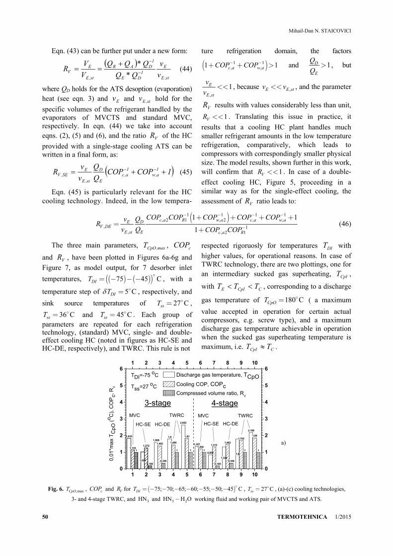
The three main parameters, max,CpOT , cCOP
and VR , have been plotted in Figures 6a-6g and
Figure 7, as model output, for 7 desorber inlet
temperatures, ( ) ( )( )75 45 CDIT = - - -
, with a
temperature step of 5 CDIT = , respectively, and
sink source temperatures of 27 CssT = ,
36 CssT = and 45 CssT = . Each group of parameters are repeated for each refrigeration technology, (standard) MVC, single- and double-effect cooling HC (noted in figures as HC-SE and HC-DE, respectively), and TWRC. This rule is not
respected rigoruosly for temperatures DIT with
higher values, for operational reasons. In case of TWRC technology, there are two plottings, one for an intermediary sucked gas superheating, CpIT ,
with CCpIE TTT , corresponding to a discharge
gas temperature of 180 CCpOT = ( a maximum
value accepted in operation for certain actual compressors, e.g. screw type), and a maximum discharge gas temperature achievable in operation when the sucked gas superheating temperature is maximum, i.e. CCpI TT .
1,835
1,1351
1,272
0,185
1,6061,402
0,356
1,8
1,459
1
2,652
1,83
1
1,3571,204
10,852
1,312
0,185
1,326
1,462
0,356
1,8
1,702
1
2,188
1,88
11,135
1
1,0291,029
1,272
1 2 3 4 5 6 7 8 9 100
1
2
3
4
5
61 2 3 4 5 6 7 8 9 10
0
1
2
3
4
5
6
HC-SE HC-DE
MVC TWRC
4-stage
0,01
*ma
x T
CpO
(o C
), C
OP
c, R
V
Discharge gas temperature, TCpO Cooling COP, COPc Compressed volume ratio, R
V
MVC TWRC
TDI=-75 oC
Tss=27 oC
3-stage
HC-SE HC-DE
a)
Fig. 6. ,maxCpOT , cCOP and VR for ( )75; 70; 65; 60; 55; 50; 45 CDIT = - - - - - - - , 27 CssT = , (a)-(c) cooling technologies,
3- and 4-stage TWRC, and 3HN and 3 2HN H O- working fluid and working pair of MVCTS and ATS.

FURTHER RESEARCH CONCERNING THE HYBRID COMPRESSION COOLING AND HEATING
TERMOTEHNICA 1/2015 51
1,689
1,263
1 0,965
1,387
0,23
1,446
1,498
0,353
1,81,63
1
2,519
1,973
1
1,259
1,334
10,801
1,429
0,23
1,201
1,558
0,353
1,8
1,903
1 2,082
2,073
1
1 2 3 4 5 6 7 8 9 100
1
2
3
4
5
61 2 3 4 5 6 7 8 9 10
0
1
2
3
4
5
6
HC-SE HC-DE HC-SE HC-DE
MVC TWRC MVC TWRC
4-stage3-stage
TDI=-70 oC
Tss=27 oC
Discharge gas temperature, TCpO Cooling COP, COPc Compressed volume ratio, R
V
0,0
1*m
ax
TC
pO (
o C),
CO
Pc,
RV
b)
1,5551,407
10,906
1,516
0,281
1,314
1,594
0,476
1,8
1,82
1
2,397
2,132
11,162
1,48
1
0,755
1,558
0,281
1,083
1,657
0,476
1,8
2,105
1
1,8
2,105
1
2
2,237
1
1 2 3 4 5 6 7 8 9 100
1
2
3
4
5
61 2 3 4 5 6 7 8 9 10
0
1
2
3
4
5
6
HC-SE HC-DE HC-SE HC-DE
MVC TWRC MVC TWRC
TDI=-65 oC
Tss=27 oC
4-stage3-stage
Discharge gas temperature, TCpO Cooling COP, COPc Compressed volume ratio, R
V
0,0
1*m
ax
TC
pO (
o C),
CO
Pc,
RV
c)
1,432
1,57
10,851
1,664
0,335
1,216
1,708
0,487
1,8
2,038
1 2,108
2,206
1 1,085
1,644
1
0,712
1,702
0,335
1,003
1,774
0,487
1,786
2,33
1
1 2 3 4 5 6 7 8 90
1
2
3
4
5
61 2 3 4 5 6 7 8 9
0
1
2
3
4
5
6
4-stage3-stage
HC-SE HC-DE HC-SE HC-DE
MVC TWRC MVC TWRC
TDI=-60 oC
Tss=27 oC
Discharge gas temperature, TCpO Cooling COP, COPc Compressed volume ratio, R
V
0,0
1*m
ax
TC
pO (
o C),
CO
Pc,
RV
d)
Fig. 6 (continued)

Mihail-Dan N. STAICOVICI
52 TERMOTEHNICA 1/2015
1,319
1,754
10,801
1,813
0,398
1,099
1,868
0,532
1,8
2,283
1
1,826
2,295
1 1,005
1,83
11,005
1,83
1
0,673
1,858
0,398
0,908
1,933
0,532
1,514
2,397
1
1 2 3 4 5 6 7 8 90
1
2
3
4
5
61 2 3 4 5 6 7 8 9
0
1
2
3
4
5
6
HC-SE HC-DE HC-SE HC-DE MVC TWRC MVC TWRC
4-stage3-stage
TDI=-55 oC
Tss=27 oC
Discharge gas temperature, TCpO Cooling COP, COPc Compressed volume ratio, R
V
0,01
*ma
x T
CpO
(o C
), C
OP
c, R
V
e)
1,215
1,964
1
0,755
2,001
0,468
1,009
2,052
0,596
1,578
2,432
1 0,937
2,042
10,836
2,118
0,6
0,836
2,118
0,6
1,303
2,535
1
1 2 3 4 5 6 70
1
2
3
4
5
61 2 3 4 5 6 7
0
1
2
3
4
5
6
HC-DE HC-SE HC-DE
MVC TWRC MVC TWRC
4-stage3-stage
TDI=-50 oC
Tss=27 oC
Discharge gas temperature, TCpO Cooling COP, COPc Compressed volume ratio, R
V
0,0
1*m
ax
TC
pO (
o C),
CO
Pc,
RV
f)
1,119
2,205
1
0,715
2,213
0,547
0,931
2,252
0,672
1,378
2,619
10,869
2,285
1
0,775
2,315
0,6720,775
2,315
0,672
1,136
2,719
1
1 2 3 4 5 6 70
1
2
3
4
5
61 2 3 4 5 6 7
0
1
2
3
4
5
6
HC-DE HC-SE HC-DE
MVC TWRC MVC TWRC
4-stage3-stage
TDI=-45 oC
Tss=27 oC
Discharge gas temperature, TCpO Cooling COP, COPc Compressed volume ratio, R
V
0,0
1*m
ax T
CpO
(o C
), C
OP
c, R
V
g)
Fig. 6 (continued)

FURTHER RESEARCH CONCERNING THE HYBRID COMPRESSION COOLING AND HEATING
TERMOTEHNICA 1/2015 53
1,835
1,1351 1,029
1,272
0,185
2,652
1,83
1
2,07
1,001
1
1,212
1,134
0,158
2,931
1,713
1
2,305
0,868
1
1,428
1,005
0,139
3,184
1,602
1
1 2 3 4 5 6 7 8 90
1
2
3
4
5
61 2 3 4 5 6 7 8 9
0
1
2
3
4
5
6
HC-SE
MVC TWRC
TM,c=Tss=45oCTM,c=Tss=36oC
HC-SE
MVC TWRC
0,01
*max
TC
pO (
o C),
CO
Pc,
RV
Discharge gas temperature, TCpO Cooling COP, COPc Compressed volume ratio, R
V
MVC TWRC
TDI=-75 oC
3-stage
HC-SE
TM,c=Tss=27oC
Fig. 7. Same as in Figures 6 for 75 CDIT =- , 27 / 36 / 45 CssT = and 3-stage TWRC.
Also, the group of parameters plotted for each
refrigeration technology form a broader parameter-technology group, which has been plotted for two TWRC configurations, i.e. 3-stage TWRC and 4-stage TWRC. Analyzing the results plotted in Figures 6a-6g and Figure 7, the following remarks can be made:
1. Concerning Figures 6a-6g first, the HC cooling technology has the most attractive values of max,CpOT , cCOP and VR parameters, in low
temperature refrigeration, out of all MVC, HC and TWRC cooling cycles analyzed (see (a)-(c) technologies). Indeed, the max,CpOT is in all cases
within the technological limits of actual com-pressors operation, the cCOP is by 10-20 percent
higher than the cCOP of the standard MVC
cooling technology and the relative to standard compressed volume, i.e. the VR ratio, is by 6 to
2 times smaller, when MVCTS and ATS are working with 3HN and 3 2HN H O- , respectively.
The VR ratio increases with DIT increase, but is
still smaller than unit, 0.67VR < , at 45 CDIT =-
and 27 CssT = . Also, the cCOP and VR ratio
increase with the number of cooling effects increase; 2. The TWRC cooling has the potential to
increase the cCOP over the cCOP of the HC
technology, but, generally, the max,CpOT of this
technology is much beyond the technological limits of actual compressors operation;
3. The HC technology offers a designer involved in low temperature refrigeration the
opportunity to use compressors with smaller physical size, which none of the other refrigeration technologies can do it;
4. As expected, the 4-stage TWRC con-figuration decreases max,CpOT , increases cCOP and
keeps the same VR , as compared to the 3-stage
TWRC, but it is more complex, comparatively; 5. Concerning Figure 7, keeping the same DIT
and TWRC configuration but increasing ssT , it
will result in a corresponding increase of max,CpOT
and a decrease of cCOP . This expected general
behavior is valid also for the HC cooling. However, in case of the HC, max,CpOT remains
within the accepted limits of compressor operation, the cCOP is higher than that of the standard MVC
and the VR slightly decreases, comparatively. This
good theoretical behavior shows much promise in the feasible application of HC not only in a cold and moderate temperature climate, but in a warm climate as well.
5. HYBRID COMPRESSION HEATING MODEL AND RESULTS
Our final analysis was directed towards the HC heating plant model. The results of a study case are given in Figure 8 (see also Staicovici, 2015b), plotting the heating effectiveness, hCOP , and the
maximum discharge temperature, max,CpOT , vs. ET ,
for RIT as parameter, ( )50 90 CRIT = - . The COPh
is similar to that calculated for the 2-stage TWRC, for

Mihail-Dan N. STAICOVICI
54 TERMOTEHNICA 1/2015
same working parameters and ,max 116 CCpOT £ .
This maximum value is smaller by up to 230ºC as compared to the maximum TWRC temperatures, (Staicovici, 2012, 2014). The results of heating HC plants show an interesting potential of the HC heating plant in heat pump applications. However, for the sake of completeness, some comments are following here. The choice of the HC heating plant at hand resulted after analyzing a few heat transformers operating in condensation absorption or with coabsorbent, such as single-stage heat transformer, truncated heat transformers or the Osenbrück. The selection criteria were the high heating effectiveness and the low discharge gas temperature. Out of the absorption compartment candidates, the Osenbrück cycle matched the best with the MVC compartment. Indeed, both subcycles of HC heating cascade have higher heat output than the heat input as the good part of the choice made. However, on the other side, the
Osenbrück cycle cannot be used effectively as heat pump in applications supplying the desorber with too low sink sources because the saturation pressure of the absorbent-refrigerant mixture would decrease considerably as compared to that of the pure refrigerant and the compressor compression ratio increases much for the same input data, with poor consequences on hCOP .
Fortunately, here comes the MVC compartment, which is put to operate with the high pressure of the pure refrigerant-low compression ratio in the low pressure region of the Osenbrück cycle, where the global HC heating plant benefit comes of with respect to effectiveness. As concerning the discharge gas temperature, the compression ratio in the two compartments can be appropriately chosen in order to fulfil optimally both criteria mentioned. If the HC heating plant temperature lift were too high, the 1st compartment can use two-or multi-stage MVC.
-15 -10 -5 0 5 10 152
3
4
5
6
5060708090
100110120130140
-15 -10 -5 0 5 10 15
2
3
4
5
6
5060708090100110120130140
50
60
70
70
8090C
OP
h, [-
], T
CpO
, [deg. C
]
Evaporator temperature, TE, [deg. C]
Hybrid Compression Heating Plant TRI -deg. C
9080
6050
TCpO
COPh
yDO=0.1; yD=0.06; TC=TRI/2-2.5
pump
=0.8
Fig. 8. hCOP and ,maxCpOT vs. ET for a HC heating plant study case, having RIT as parameter.
6. CONCLUSIONS
The HC technology exhibits top qualities in cooling and heating: a) it benefits of the ATS operation which is independent from the external heat supply because it is capable to work like a MVC unit, with just two external sources supply, a sink source and an electrical or mechanical source; b) it benefits of high cooling and heating COP, similar to that of 2- 4 -stage TWRC, but at low discharge gas temperatures, compatible with today compressor technology; c) its use is mostly indicated in the low temperature refrigeration, for replacing the MVC by a MVCTS-ATS synergeia
in order to handle low density refrigerants, the compressor physical size results much smaller, comparetively; d) given the HC enables the ATS operation with internal low sink and heat
temperatures, e.g. ( )( )0 35 C- -
and ( )30 45 C-
, respectively, for usual external sink temperatures
of ( )25 40 C- , in case of volatile absorbent
working pairs use, e.g. 3 2NH H O- , the plant absorption rectifying device results with reduced complexity, or can even be eliminated completely from the flow diagram, and the cooling ef-fectiveness of ATS and HC increase.

FURTHER RESEARCH CONCERNING THE HYBRID COMPRESSION COOLING AND HEATING
TERMOTEHNICA 1/2015 55
NOMENCLATURE
ATS - absorption technology section COP - coefficient of performance HC - hybrid compression HA -hybrid absorption MVC - mechanical vapor compression MVCTS - mechanical vapor compression techno-
logy section p - pressure, bar Q, q - heat, kJ, kJ*kg-1 RV - ratio of the compressed volume of a
certain cooling technology through same of standard
T - temperature, ºC, K TWRC - thermal-to-work recovery compression TTRC - thermal-to-thermal recovery compres-
sion V, v - volume, m3, specific volume, m3*kg-1
W - mechanical work, kJ y - mass fraction, kg*kg-1 Greek
- difference - density, kg*m-3
- efficiency Subscripts
a - absorption A - absorber c - cooling, compression C - condenser CpO, CpI - compressor outlet, compressor inlet D - desorber DE - double-effect DI - desorber inlet DO - desorber outlet E - evaporator G - generator GO - generator outlet
h - heating HC - hybrid compression id - ideal int - intermediary mvc - mechanical vapor compression M - mixing point max - maximum Osbrck - Osenbrück cycle p - pump R - resorber RI - resorber inlet ss - sink source st - standard SE - single-effect V - volume w - work
REFERENCES
[1] Staicovici M. D., 2011a. A method of improving the effectiveness of a mecanical vapor compression process and of its applications in refrigeration. Int. J. Heat Mass Transfer, 54 (2011) 1752-1762, doi:10.1016/j.ijheatmasstransfer. 2011.01.016.
[2] Staicovici M. D., 2011b, c. A Thermodynamic Approach Of Mecanical Vapor Compression Refrigeration COP Increase. Part I: Methods and Ideal Limits; Part II: Ther-mal to Work Recovery Method Applications. Proceedings of the 4th IIR Conference: Ammonia Refrigeration Technology, Ohrid 2011.
[3] Staicovici M. D., 2011d. Climbing the thermodynamic effectiveness summits of mechanical vapor compression cooling through discharge gas heat conversion: a theoretical approach, Proceedings of the ICR 2011, Prague.
[4] Staicovici M. D., 2012, Thermal-to-work and thermal-to-thermal recovery compression heat pumping, Proceedings of the 10th IIR Gustav Lorenzen Conference on Natural Refrigerants, Delft, 25-27 June 2012, the Netherlands.
[5] Staicovici M. D., 2014, Coabsorbent and Thermal Recovery Compression Heat Pumping Technologies. Berlin-Heidelberg: Springer Verlag, 2014.
[6] Staicovici M. D., 2015a, Hybrid Compression Heat Pumping Cycles Based Plants, European Patent file, EP15075005.7/ 29.01.2015.
[7] Staicovici M. D., 2015b, Hybrid Compression Heat Pumping Cycles Based Plants, Accepted for publication to the 24th International Congress of Refrigeration, 16-22 August 2015, Yokohama, Japan.