Further information under 250works-manual.pdf · The special tools described in this workshop...
17
Transcript of Further information under 250works-manual.pdf · The special tools described in this workshop...

DKW Geyer
Further information under www.dkw-geyer.com

The special tools described in this workshop manual for IM Potorcycles RT 2UG / RT 250
tan be purchased fror our SERVICE DEPARTMENT at IRGOlSTADT / KMU, Garmany.
Rhen erdering parts please note:
1. Addrutss all cornspondence to
AJJTO l!!llU4 G.in.b.H. ExporLSewice
Ir,
Telephones: 2993, 2771-73
Cables: AUTUN IQY INGOLSTADT Germany.
2. Always quote exact quantity of tools or Parts requiFed and do not oait also to
quote the Parts number.
3. Please quote whether the goods an to be dispatched by Sample pest, air fnight,
sea fnight etc.
4. Always giva exact addms of destination, othamise delays am unavoidable.
5. Please platze ywr orders for tools and Parts separately, not in ccmection with
1etters.
6, Tenns of payrnent will be fixed individually. (Bankers cheque in advance, letter
of credit etc.)
7. In case of inquiries please always quote our refemnce and Order nunbers.
8 . Claims IV.& be placed w”%fn 8 days an maipt of goods.
9. Place of settlement: Ingolstadt/Donau, Gennany.
10. Na merve the right to make changas in design, to Rake additions or improvemnts
on our pruducts without previous notice and without incurring obligation to

Ic ins>all the sam on compcrmts or assamblies pmviwsly supplied.
NOTE: The +otoqmphs and drawings shm in tha secml part of this booklet will
facilitate accwate nfemce to the described stripping and refitting werk.
2
NT0 IHICW G. m. b. H.
.
rORKSHOP MANUAL
DM tiotorcycle Engine , models RT 200 and RT 250
See descriptive illustration,
table 1
Single cylinder - DKW - Two-stroke Engine with IM reverse-scavenging - flat top Piston
with thme rings - special light alloy cylinder head.
RT Perfotmance: 1OfMP - r.p.m.: 4!jOO - Eope: 62 m 0 - Stmke : 64 nun - cubic
capadty : 244 C.C* - Cmpmssion ailo: 1 : 6,3 - Combustion chamber : 46 C.C.
kition and generator System: RT 2Illl : *--
DWbattetydgnition and lightiog systea 6 volts 45/60 Watts sparking plug: 80~1% VI
115/ t 1 OPBBN m/14.
250: RT
As urith RT 200, but w;ith sparking plug, Bosch I 2251 Tl or Betu 225/14.
Cartumtterz
RT 200:
Air set SCWY 2 112 turn open.
Bing carbmtter AJ 1124 up to eqine nuaber 4700WlI - fiteI jet: 100 - neadle positi-
on 2 ( needle position 3 up to 1ooO kilometen) - needls Jet 270 - idlinp Speed jrt SO-
air scruw: 1 112 turn open - mixing chamber insert: rize 5

Together with the carbumtter F 1/24 a nea crankshaft with full counterdeights was in-
tmduced. If a crankshaft of fomar pmduction is to be raplacadby a cmnkshaft with
full weights, the carbumtter setting must be modified as follows:
Fuel Jet 105/ - air set screw 2 1/2 tums open.
If an the other hand an engins fitted with flangc catimtter F 1/24 without inter-
mediate pipe ) is to be equipped with a crankskaft of the old typa, the carbumtter
setting should be modified in the following way:
Air set screw 2 1/2 turrs open.
@;
Birg carhumtter AJ 2/26 - Fuel jet 105 - needle position 2 ( needle Position 3 up
to IOUI kiloeeters ) - needle jet 270 - idling speed jet 60 - air set scraw 1 112
turne open - mixing chamber insert size 5.
Clutch : ---.
Alultiplate clutch in cil bath - endlass mller Mn betweon enpine and gear box -
tmnsnission ratio 1: 2.53 for RT BI3 and RT 2%
Thmrapeed gear box ( foot ltvsr contml with electric neutral position indicatcr).
Gear box :
E200andRT 250:
Gear mtio : First speed 1 : 2.66 - srcond spaed 1 : 1.378 - thitd speed 1 : 1
Chain drive : --e-v--
RT. 2UO * ---L
4
Roller chafn 1 7/2 x 5/16* -Solo : gear ratfo 1 : 2.5 - drive sproeket 19 teeth - side
car : gear Mio 1 : 3,2 - driva spmcket 14 teetb - whsel spmckt 45 teeth.
250: RT.
Roller chain 1 112 x 5/16” - solo: gear ratio 1 : 2,5 - driw Sprocket 19 taath - side
car : gear ratio 1 : 3 - drive spmcket 15 teeth - whsel spmcket 45 teeth.
Total transmission ratio:
RT2lO:
First Speed : 1 : 16,8 - second Speed 1 : 8,72 - third spaed 1 : 6,34 .
RT25U:
First speed 1 : 16 - second speed 1 : 8,3 - third spead 1 : 5,99 .
It fs essential that in addition to the Standard tools ths following spacial tools ba
available for strippinq and n-fitti& RT 2?30/250 eqines.
See illustmtion
table 2
No. ? = Clutch munter support ..,..........,.....‘............... No. 0100253-0
No. 2 = Chain spmeket extmctor . . . . . . . . . . . . . . . . . . . . . . . . . . . . . . . . . No. 0100248.0 ( tan 21~0 bc wad for Rt 125 instead of No. 0 . . . . . . No.
No. 3 - Hook Spanner for exhaust Pipe collar nut 52 - 55 . . . . . . . . . . . . . . . . . . . . . . . . . . . . ..*............... No. 0903
No. 4 l Extmctor for con. rod hrshss with 15 BITI/@ . . . . . . . . . . . . . . . No. 0969

No. 5 l Clutch spring pullar . . . . . . . . . . . . . . . . . . . . . . . . . . ..e.........
No. 6 . Piston ring compraasor ....................................
No. 7 l Piston hnter cap .........................................
. Elsctric Piston hratrr ....................................
with heatw alement .......................................
No. 8 . Conmd tush rm>ool .................................
No. 9 . Punch for oil saals and ball borrings .....................
No. 10 . Holder for chain Sprocket .................................
No. 11 . Clrping pitce ( to ba ussd with No. OltlX!M) ...........
No. 12 . Raducing pitca for ignition tiaing gauga ..................
No. 13 l Ignition timing gauge .....................................
No.14 - Guide sleeve ..............................................
No. 15 - Annatura axtractiq holt ..................................
No. 16 . Punch for Piston pin ......................................
No. 17 . Guide twi for Piston pin ..................................
No.18 . Extnctorrod fordmvels ..................................
No. 19 . Fork for countarreight support ...........................
No. in . Rooden forl< for Piston munting ...........................
No. 2l . Rulrr for alfgniq con-md ................................
6
No. OlOO'l61
No. olooa1-0
No. mom60-o
No.oloOl47
No. mool45
No. OlGGll9~
No.olaIa2xl
No. olm246-0
Na. Olm2444
No. olm~54
No. 0766
tb.ol002450
No. OlOOO27
No, rnoo249d
No. olm2494rl
~o,moc243~
~0.mm2540
No. mom62
No. 0100156
No. 22 l Aligniq pin for ton-rPd . . . . . . . . . . . . . . . . . . . . . . . . . . . . . . . . . . . . . . . . No. OlWl3
No. 23 . Gauge pin for ton-md ........................................... No. OlOO214
':i:"i .
(wi thwt
. Box spanner ..................................................... No. olop6B-o
ill) . Piston ring expander ............................................ No. 0162
See illustration
table 3
Crank shaft axtracter complete . . . . . . . . . . . . . . . . . . . . . . . . . . . . . . . . . . . . . . . . . . . kLrnal266~
Engine support for use with enginas RT 125, RT. 200 and RT 250 ( sea ill. 1 ) _ No. 0100269-0 . . . . . . . . . . . . . . . . . . . . . . . . . . . . . . . . . . . . . . . .
Before fixiq cqins in thc support and aounting in vice, drain gear Oil.
The eng& support nursbsr~269~ consists of a U-plato to ba used forthe models RT 125,
RT 2UG and RT 250, and rhich tan be turned in all dindions, withthe aid of a joint-
piece, further of a bracket holding the joint piece in the vio and of various - indi-
vidually rr&ed - bolts.
Ths markings on the bolts show which of thea ars needed forths RT 125 and which ara
intended for the RT 200 / 2% models.
See illustration
table 4
Place engine support in horizontal position and lay ths engine - clutch side downwards
on top, then fix with the bolts supptied. The bolts arm also intended as supports for
the trank shaft extractor ( see ill.17 ).
7

New bring eqine with support in a vertical position as shown in the i11.4, tighten
handle sewrely in joint piece. Unscmw generator cover, extrad the ngulator with WI,
mmove the clutch thrust md and mbber seal and also the switch for the neutriil position
indicator.
See illustration
table 5 t 8
Loosen connections 1,30 and Dt on rcpulator and genentor switch spanner No. OlOU268-0 i i
and pull out wiring in ths dinction of the clutch side. Take out the rubber gmmtrtit. : 1
Unscrew the two bolts’holding the generator and remove field winding together with PB- i
gulator and contad breaker basc plate.
Extact the armzturs rith otPPtuie’Oxtrsldfqvbollt;anl ndvtlha). Insert chain
Sprocket holder No. Ol@246-0, loosen leck plate and qt. Attention ! Left hand
thrsad ! Reek%e flaqe with Paper gasket, washer and oil conductiq disc, Extrakt
chain spmcket and cover plate with Paper gasket, oil seal and rate.
Reaove the foot Change and kickstarter trank with aid of a SCF)W driver, haviq
praviously locsened the clampiq bolts. Unscrsw five cover bolts ( Attention :
Washsrs !) Renove cover and gasket, check chain slack ( slack: Total width up and
down). If slack exceeds 15 me (19/32 inch) replace chain. Remove washer fmm kickstarter
shaft. If chain is to be ra-used, mark same on the outside.
See illustration
table 8
Pu11 out the five clutch spriqs with puller No. OllN161, turn by 90’ to the left and
then let ths spriqs snap back. Remove clutch components. Note Position of’lined- and
steel plates ! Insert clampiq piece No. OlUO244-0 and remove chain Sprocket nut
( right hand .thrsad).
See illustration
table 9
Remve extractiq holt, insert clutch counter support No. U’ioO2536 and clamping piece
Ol00244-0 and also loosen cl~tch tage rm~t. ( Left iad thraad !) Remove drive brackst.
Sse illustration
table 10
Scrvw the chain sprockzt extractor G100248-0 to spmcket ad extrad fron trank-shaft.
The entire drive unit incl. chain and kickstarter assembly tan mw be ramoved. Note
Position, wantity and thickness of washers behind the clutch drum. These arv im-
portant for adjustiq chain aligtneent.
See ill*tration
Zahle 11
Nee the four nuts securiq ths cylinderhead should be unscmwed. A suitable spanner
No. 4701~ao3-00 is supplisd with the rotorcycle tools. Remove cylirxterhead, gasket,
9

cylinder anJ base gasket, and da not forget, immediately, to insert wooden fork %I.
UTOOl62, to avoid damaging the pisfon.
See illustration
Gable 12
NW hast the Piston rith the piston heoter ap No. 0100260-0 or the elactric Piston
hea~er @@Ul47 t MYl45 up to ab& SooC, ( 125 deg F), having mmoved ths cinlips
bofomhanJ,. Then press the gudgeon pin out $y band vSth the aid of a punch.
See illustmtion
table 13
fiaving meoved the two boltc fmn the eyine support, the doxelo tan be pmssed out
tiith help of the Punch OloO243=& Hove ton-.md !o bottom dead centm posftion and
ins& auppori fork No. 01002!%=0 between fhe iouder reights, her& applying a
fa4 light stmkes so that the krk fits Iightly. Turn the engine by lal” , tilt into
hori&al Position and mmove the 12 case bolts on the clutch side and the thirtaenth
holt on ths generator side. For thls Operation P stmng uell-fittiq ssmw driver :s
ssSkdid1.
See illustntisn
table 14
Fix the th& piece of crankhaft edmdor with the thme attached bolts on 4he
shaft end (genemtor side ). Then mmova the support bolts fr-sa the txtractor and
jv tiyMening the thw;t bolts separate the halves of the case,
See i llustmtion
table 15
10
See illustmtion
table 16
The gear componerrts, the shift shaft and the gear laver uith bear!ng, stop ball and
sprirg tan be rasily mmoved after uuscmuing the tro bolts ( loosen leck plates
befomhand ).
Sec illustmtion
table 17
After tuming ths engine accordingly so that it 3s in a horizontal position, fix th
cmnkshaft axtmctor, having befomhand fixed the holt frum beneath and two further
s~pport bolts. The ans half of the case with crankshaft now hangs benaath the extrac-
tor. Befom fixing the plate insert the thmsf piece fma bemath so that the bead lies
against the plate. Ths crankshaft tan mw be easily pmssed out of the bearing by
sinply tightening the thmst holt.
Now mwve tha crankshaft extmdor. Should both ball bearings have maained in the
case ( clutch side ) rhilst extracting the crankshaft, then one of the bearinps aust
be mnoved befom pmssing out ths oil seal and the second beari’ng, so that the
cimlip l between the two bearings - tan ba maved, By waning tha case camfully amund
the bearing seat with ths aid of a gas flans and tapping the case an a wooden block, the
barring will dmp aut fmtn its seat.
See illustration
tab1e 13
11
After placing tha case into the engina support again the oil saal and the second ball
bearing tan be pmssed out with aid of tha punch No. OlOO2524. lhis ran of COUISO

also be done without the online supporL
See i llust rat ion
table 19
The neutral Position indiator shaft tan then be ramved withcut difficulty from the
case (generator side) arxi with a mbber mallet the ohaft goar tan be driven out of
the ball beatitq Saat.
If the ball bearings also haw to be Mmved, the case mst be heated and the bearings
driven oti with the punih No. Ct’lDD2jZ-O.
8hen reassembling ,the eng&
do nd mit to hont the bearing seats to about EO - So C ( 180 - 135 deg. F) before
insartiy tha ball bear;ys. Fix th3 oil seal so that the lip poitrts in dimction of
the clutch. As far the oil seal 1s Rtt nrbbacovered, sealirq compound should be applied
to the cirwnference of the &al seal holder. Remove any nmins of the sealiq coa-
pound which may nnain on the bearing se&s beforp fixing the ball bearings .
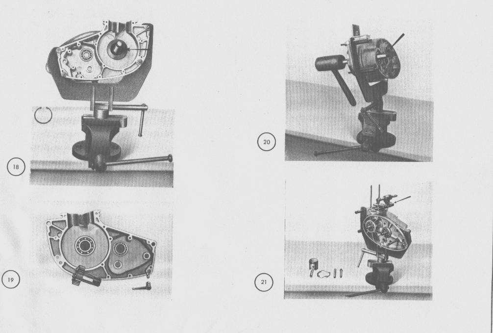
See illustration
table 2U
To avoid darnage of ths oil seal lip whan fixing the crankshft plam guide sleeve OlOD245-
0 on tie shaft end ( clutch sida ). If the cnnkshaf? is wt to be prassod into the caso
bi a special Pro, thrn use only Nbber Qallet or a piea of ha&ood and do not foqet
the wunter weight support OlOD84~. Having fixed the gears arvl shift rochanism, briy
gean tiith aid of foot levar into second Speed position and check I follows:
As shoin in ill. 15 the jaws of ths shift piea should be in oqual distance fror the
12
shift bracket edges ad the points of the jaws must awer half the brpadth of the shift
bracket. Should the coverage not be con& the support angle nust be carefully
adfusted. If the distana on both sides is not 0~~1, then the ends of the retum spriq
ust be slightly bent with the aid of a tubular punch. NN Maate the gear ohaffs and
mum that all Parts wo& smothly.
Before fixing the right half of the case apply a good ssalitq anpound to the joint
surfaces. All bolts aust be tqually tightcned with a weil-fitting screrdriver. DO
not ~rnove countenveight support u>til this work has bwn cunpleted.
See illustration
table 21
Fi?ally control the ton-rod alignnerrt with aid of gauJe No. OlKl213, ruler No. O’lDO’l56
and one aligfling md No. OlDD2l3. We also refer to the illustratiorr; in ourSpecia1
Tools Booklet No. 77, when the handling of thase tools is describad. Should the
replacement of the ton-rud bush appear necessary, use bush extractor No. 0969 and
,IPWI the nee bush with rearing tool Yo. Oloo119-Q.
The adjustable FBuRer is - YB should like to point out - the same as usod for the
DM oIr engine. The mamer is availabls under No. OlDDlO9-3.
Gudgeon pin clearance should be 0,02 to O,O3 nm. Wen rpving the gudgeon pin tan
be used rs gauga.
For insertin the gudgeon pin into the Piston rhich has been proviously heated to
SO’C ( 125 deg r), use the guide md No. 010024901 and for prassing the pin bi hand
into its final position use guide pin No. OlOO249=0, which autanatically ~WIU~ the
corract location of the gudgeon pin in the Piston. Piston cleannce: 0,05 m .
13

UM assembliq clutch and chain spruckats, check chain alignlent. First fit spruckets
without chain, as this facilitatas checking of the cormct position of the tooth flangas,
which ust IM in one plane. Adjmtment tan be made by the washers bebind the cluth tage,
almadi aentioned against ill. 11. Further make sure that thj bush pmtudes abmt 0,l to
U,2 IRR; so that the inler clutch plate drum mns perfectly fwe.
Although the cover on ths clutch sido carries a Paper gasket, use sealing compound rhen
fixing.
See i llust rat ion
table 22
fhen fit tinJ genemtor, alwys n~ve the carbon bmsh taps and aithdrar the brushas to
aiuid danage. The angle of the contact bnaker ans msf be graassd befonhand ( i.e.,
Shell Oonax P, Callypsol etc.). The felt wipor itself shwld not ba greased. Felts which
have become hard aust be mplaad to avoid unlue wear of the caw.
When reconnecting ths wiring, take care that tha rubber stals arc pmperly fitted in
the case.
To adjust ignition timing :
1. Set contact gap at 0.4 ITQI when cae is at highest posi,tion.
2. Scnr ignition timinp gauge No. 0736 with mducing piece 0100265-0 ( see ill. 23 )
into sparking plug apertum and mise Piston by neans of the kickstarter to
5,5 11y11 ( 1132 in& ) befon top il&d centre. T.D.C. is positionad automaticelly
by the ga]a slide rhen mtating th enqine. DO not turn the ignition ngulator !
Conwct test las?. Rhen engina is out of tha fnme the lamp must be connected in
series with ths contad bnaker points, i.e., tha lamp should 5s connected exactly
14
like an aspermeter, either in the positive or negative lead. The lamp will go out as soon
SS the bnaker Points begin to open.
3. Expand tha fly weights by hand and insort a cr11 piece of wood or a natch in the
comer bettieen plate and fly weight to pmvant the weights fnxn returnin& In this
Position the test liup should just go out, if not, the contact bnaker base plate
ust be adjusted until the corvect ignition point is mached.
For this purpose first loosen scmw A and with aid of a comer scruwdriver, the
screw B is partly covered by the ignition mgulator. Row turn base plate to right
or left as necessary and n-tighten both scmws. Ropeat Operation if necessary.
For uettiy the ignition the wver on the geneator side must be maoved in Order
to roach scraw B with a wmer acrswdrivar. If the ignition is only to be
chrcksd, withwt any adjustRant, this tan be dona by way of the contra1 apertum,
heving befonhand mmovod the lid. If the ignition gauge No. 07B6- dasigned for
the OKU! car engine - is to be used for the RT 2OD/2%l engine, thc mducing piece
aust be scnred on and furthar m II) the pointar holt ust be shortened at the
larer ond by 5 AIIB to 30 mm, so that the holt maches far enqh into the
cylinder. In spite of this modification the gauge tan still be used for the
car engina.
( In futuw the gwges will be supplied with a lengthened pin, so that the above
oparation will bewar unnecessary.)
15