Fundamentals on light scattering, absorption and … · Fundamentals on light scattering,...
39
Fundamentals on light scattering, absorption and thermal radiation, and its relation to the vector radiative transfer equation Klaus Jockers November 11, 2014 Max-Planck-Institut für Sonnensystemforschung
Transcript of Fundamentals on light scattering, absorption and … · Fundamentals on light scattering,...

Fundamentals on light scattering, absorption and thermal radiation, and its relation to the vector radiative
transfer equation
Klaus Jockers
November 11, 2014
Max-Planck-Institut für Sonnensystemforschung
Outline of talk:
Motivation: Provide some background on scattering and thermal radiation to researchers interpreting observations of asteroid and comet surfaces
1. Transversal waves → Polarization must be taken into account! Characterization of polarization.
2. Scattering of electromagnetic radiation by an arbitrary, finite particle in the far-field zone
3. The optical theorem
4. Thermal radiation
5. Diagrammatic representation of scattering processes – scattering by random, discrete scatterers
6. Vector radiative transfer equation

Literature:
Mishchenko, M.I., L.D. Travis, A. A. Lacis: “Scattering, absorption and emission of light by small particles”, Cambridge Univ. Press, 2002
Bohren, C. F., D. R. Huffman: “Absorption and scattering of light by small particles”, Wiley, 1983
Tsang, L., J. A. Kong, R. T. Shin, “Theory of microwave remote sensing”, Wiley, 1985
Tsang, L., J. A. Kong, K.-H. Ding, “Scattering of electromagnetic waves, Theories and applications”, Wiley, 2000
Ishimaru, A., “Wave propagation and scattering in random media”, Academic Press, 1978
Morse, Ph. M., and H. Feshbach, “Methods of theoretical physics”, 2 Vols., McGraw-Hill, 1953-
In my presentation I follow mainly the book of Mishchenko et al.

Outline of talk:
1. Transversal waves → Polarization must be taken into account! Characterization of polarization.
2. Scattering of electromagnetic radiation by an arbitrary, finite particle in the far-field zone
3. The optical theorem
4. Thermal radiation
5. Diagrammatic representation of scattering processes – scattering by random, discrete scatterers
6. Vector radiative transfer equation
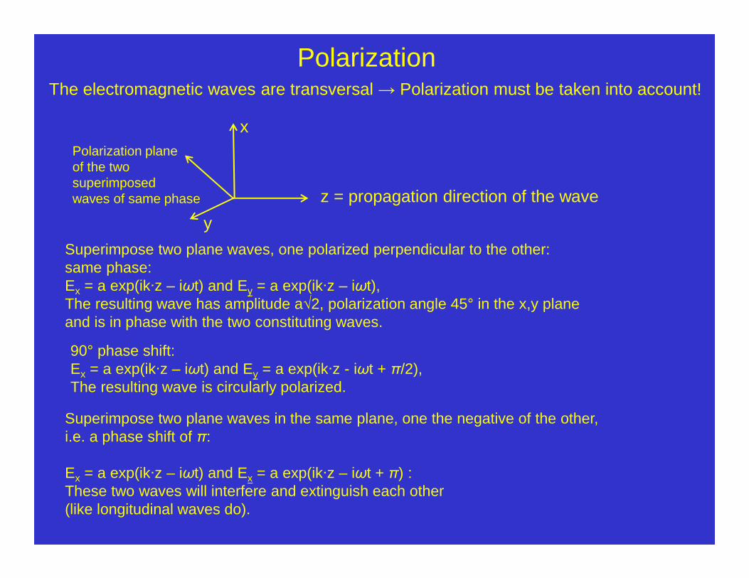
The electromagnetic waves are transversal → Polarization must be taken into account!
Superimpose two plane waves, one polarized perpendicular to the other:same phase:Ex = a exp(ik·z – iωt) and Ey = a exp(ik·z – iωt), The resulting wave has amplitude a√2, polarization angle 45° in the x,y planeand is in phase with the two constituting waves.
y
x
z = propagation direction of the wave
Polarization planeof the twosuperimposedwaves of same phase
Polarization
Superimpose two plane waves in the same plane, one the negative of the other,i.e. a phase shift of π:
Ex = a exp(ik·z – iωt) and Ex = a exp(ik·z – iωt + π) :These two waves will interfere and extinguish each other (like longitudinal waves do).
90° phase shift:Ex = a exp(ik·z – iωt) and Ey = a exp(ik·z - iωt + π/2), The resulting wave is circularly polarized.

Superposition of two waves with orthogonal linear polarization and different pase.
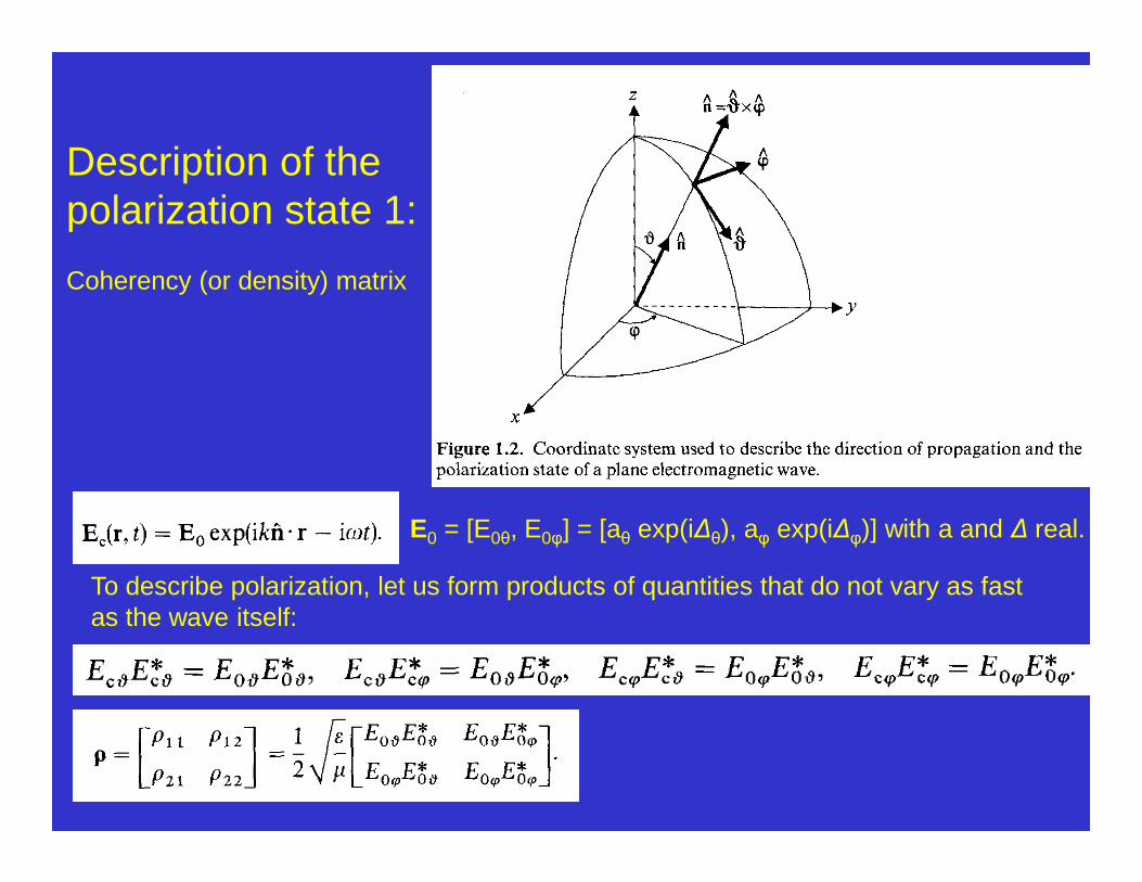
Description of the polarization state 1:
Coherency (or density) matrix
E0 = [E0θ, E0φ] = [aθ exp(i∆θ), aφ exp(i∆φ)] with a and ∆ real.
To describe polarization, let us form products of quantities that do not vary as fast as the wave itself:
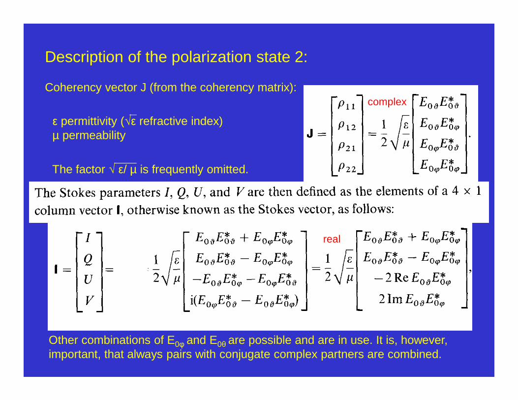
Description of the polarization state 2:
Coherency vector J (from the coherency matrix):
ε permittivity (√ε refractive index) µ permeability
The factor √ ε/ µ is frequently omitted.
Other combinations of E0φ and E0θ are possible and are in use. It is, however, important, that always pairs with conjugate complex partners are combined.
complex
real

Quasi-monochromatic light 1:The previous definition of the coherency and Stokes vectors implies that the waves are strictly monochromatic, i. e. E0 = [E0θ, E0φ] = [aθ exp(i∆θ), aφ exp(i∆φ)] and the real amplitudes aφ and aθ, and phases ∆φ and ∆θ are exactly constant.
But in reality there is no strictly monochromatic wave. Amplitudes and phases vary, but much less than the oscillating electric field itself.
We must replace the amplitudes and phases themselves by their time averages.

Quasi-monochromatic light 2:
For strictly monochromatic light we have I2 = Q2 + U2 + V2.
For quasi-monochromatic light we have
≥ 0
Quasi-monochromatic light 3:
Corollary:Highly monochromatic light like laser light easily produces speckles, caused by interference. We expect in such cases the polarization to be high:
I2 = Q2 + U2 + V2 ≈ 1.

Outline of talk:
1. Transversal waves → Polarization must be taken into account! Characterization of polarization.
2. Scattering of electromagnetic radiation by an arbitrary, finite particle in the far-field zone
3. The optical theorem
4. Thermal radiation
5. Diagrammatic representation of scattering processes – scattering by random, discrete scatterers
6. Vector radiative transfer equation

Incidentlight
Incidentlight
Scattering by an arbitrary, finite particle:
The “particle“ can be a single entity or a small group of separate entities.
The particle is embedded in a loss-free medium (e.g. vacuum).
The incident light enters the particle and induces electrical dipoles in it. The dipoles radiate secondary waves and in this way generate the scattered radiation. In turn, the generated radiation influences the strength and direction of the dipoles.
The Discrete Dipole Approximation calculates the scattering by directly determining the dipoles, but I will use the approach of macroscopic electromagnetics, i.e. describe the particle by its index of refraction.
Vint, everything else is Vext

Assumptions:1. Time-harmonic, quasi-monochromatic light ~ e-iωt.2. No frequency redistribution, scattered and incident light have the same frequency.
If radiation energy is transferred to a different frequency this is considered as absorption.
3. Only finite particles are considered.4. Only scattering in far-field zone, i.e. distance of observer » wavelength and extent
of particle.5. Bound host medium surrounding the scatterer is homogeneous, linear, isotropic,
and nonabsorbing.6. In the following we assume host medium and scattering object as nonmagnetic:
µ2(r) ≡ µ1 = µ0, where µ0 is the permeability of vacuum.(Vint ← index 1, Vext ← index 2.)
At the surface of particles the well-known boundary conditions must be observed:Etangential and (in the absence of surface charges) Dnormal = Enormal/ε must be continuous.

Equation to be solved:
In brackets: tensor, i.e. linear vector function. Einc(r): incident plane wave.
Result equation:
The result equation can be solved, e.g. by iteration, entering E = Eint as a start on the right side. It must be solved for all possible polarization states of Einc(r).
k: wave number, m: refractive index, r position vector

note:In electrostatics we have for the electric potential Φ:
Φ = ∫ d3 r ρ(r’) / Ir - r’I (ρ charge density),
a similar Green function as in the previous projection.

Outline of talk:
1. Transversal waves → Polarization must be taken into account! Characterization of polarization.
2. Scattering of electromagnetic radiation by an arbitrary, finite particle in the far-field zone
3. The optical theorem
4. Thermal radiation
5. Diagrammatic representation of scattering processes – scattering by random, discrete scatterers
6. Vector radiative transfer equation

Lens and stop define the acceptance angle. Plane optics in front of the detector (not shown) allows to measure all Stokes parameters. The lens images the stop into infinity. Intensity is area x acceptance cone.Detector 1 looks into direction of the incoming light and observes the extinction.Detector 2 observes the scattered radiation.
Optical theorem 1:Detector: ∆S is the detector area. Size of particle « ∆S « r (distance to scattering object)

Optical theorem 2:
W∆S: Total electromagnetic power received by detector 2S(r) is energy flow (Poynting vector) in any direction away from direction of incident wave.dS element on detector surface. ∆S detector area. Esca
1 electric field in embedding medium in the far field (depends on direction).
W∆S (ninc): Total electromagnetic power received by detector 1.First term like scattered radiation, second term is an attenuation term independent of ∆S.

Optical theorem 3:
Energy conservation in the scattering process:
Energy is removed from the incoming beam, partly absorbed in the particle (i.e. transferred to another frequency), partly scattered.
Extinction: The light in the incoming beam, after it has passed the particle (forward scattering):
Scattering (except forward scattering)
Optical theorem: The energy in the scattered light (except forward scattering) equals the energy removed by interference between incoming and forward scattered light.
Wext = Wscat + WabsDivide by ½ √ε1/µ0 IEincI2 to get the cross-sections Cext, Cscat, and Cabs.The scattering cross-sections are always larger than the geometrical ones.

Phase matrix and extinction matrix
Stokes vector of scattered radiationZ Phase matrix
Stokes vector received by Detector 1“Extinguished” radiationK extinction matrix

Digression:
Extinction is possible without absorption:Examples: Interstellar dust and Schott® shortcut filter glasses

Outline of talk:
1. Transversal waves → Polarization must be taken into account! Characterization of polarization.
2. Scattering of electromagnetic radiation by an arbitrary, finite particle in the far-field zone
3. The optical theorem
4. Thermal radiation
5. Diagrammatic representation of scattering processes – scattering by random, discrete scatterers
6. Vector radiative transfer equation

The thermal radiation emitted by the particle is characterized by a four-component column Stokes vector pointing radially away from the particle in the far field. In this thought experiment the particle is embedded in a cavity. In the cavitythe radiation is a collection of quasi-monochromatic, unpolarized, incoherent beams propagating in all directions with the Planck blackbody energy distribution
The detector is in the far field of the particle.The cavity size is much larger than the distance of the detector from the particle.
The acceptance angle of the detector is selected to cover the particle in its full field.

In the absence of the particle the polarized signal per unit frequency intervalmeasured by the detector is
In the presence of the particle the polarized signal measured by the detector is
Planck cavityradiation
Radiationto be “extinguished”
Radiation to be scattered
Radiation emittedby particle
Radiation “extinguished”by particle
Radiation scattered by particle
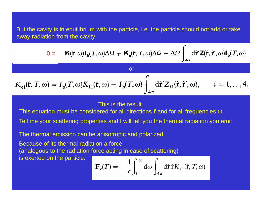
But the cavity is in equilibrium with the particle, i.e. the particle should not add or take away radiation from the cavity
0 =
or
This is the result. This equation must be considered for all directions ȓ and for all frequencies ω.
The thermal emission can be anisotropic and polarized.
Because of its thermal radiation a force (analogous to the radiation force acting in case of scattering) is exerted on the particle.
Tell me your scattering properties and I will tell you the thermal radiation you emit.

More on thermal emission can be found in the book:Tsang, L., J. A. Kong, K.-H. Ding, “Scattering of electromagnetic waves, Theories and applications”, Wiley, 2000, Chapter 3.5, “Fundamentals of random scattering”, “Passive remote sensing”, in particular about the fluctuation dissipation theorem.
Also in the older book:Tsang, L., J. A. Kong, R. T. Shin, “Theory of microwave remote sensing”, Wiley, 1985, there is a lot about thermal emission, as microwaves are mostly emitted via thermal emission.
Outline of talk:
1. Transversal waves → Polarization must be taken into account! Characterization of polarization.
2. Scattering of electromagnetic radiation by an arbitrary, finite particle in the far-field zone
3. The optical theorem
4. Thermal radiation
5. Diagrammatic representation of scattering processes – scattering by random, discrete scatterers
6. Vector radiative transfer equation

Up to now we have treated only the scattering in the far field.The methods to be shown very briefly now, can in principle be applied to dense media as well.
In the past I have collaborated with Viktor Tishkovets, Charkiv, Ukraina. There has been some progress concerning compact random media.

Scattering by many, not necessarily equal particles.Particles may be densely packed. Scattered light illuminates other particles and is scattered by them.
We consider the scattering in such a cloud as a sequence of scattering events on individual particles. Consequently we consider scattering orders, single scattering, double scattering, … , multiple scattering.
α is the phase angle, i.e. the angle light source – particle – observer.

Illuminating sourceobserver
Single scattering
Electric field = E1
1
2
3
+ E2 + E3
α

Illuminating sourceobserver
Double scattering
Electric field = E12 + E21
1
2
3
+ E23 + E32 + ...Note: For small phase angles α waves E12 and E21will always be coherent, no matter if the distance between particles 1 and 2 is comparable with or larger than the wavelength. This causes the coherent backscattering effect.
If and only if the distance between particles 1 and 2 is comparable to λ waves E1 and E2 are coherent with waves E12 and E21.
Triple scattering ...
α

For the electric field of our 3-particle cluster we have:
E = E1 + E2 + E3 + E12 + E21 + E13 + E31 + E23 + E32 + (eq. 1)+ E123 + E231 + E312 + E132 + E321 + E213 ++ E121 + E131 + E212 + E232 + E313 + E323
For a larger cluster we must take into account the higher scattering orders.
To calculate the Stokes parameters we must form the expressions
I = <Epar E*par> + <Eperp E*perp>Q = <Epar E*par> - <Eperp E*perp>U = <Epar E*perp> + <Eperp E*par>V = <Epar E*perp> - <Eperp E*par>
From the linear sum of the electric fields we get bilinear sums for the Stokes parameters in which each term of eq. (1) is combined with all other terms.

Consider pairs of paths through the cloud of particles and let them interfere.
Most of the paths be can considered uncorrelated, i.e. they will not interfere.

2 waves interact (full and dotted lines).n, p and µ, ν can have the values ±1, i.e. there are 4 components for the 4 Stokes
parameters for each wave.(a) Single scattering (b) Ladder diagrams: incoherent (diffuse) scattering(c) Cyclical diagram (coherent opposition effect)(d) and (e): Generalization of (b) for the interference between different scattering
orders (possible only in a dense medium with particles of size comparable to or less than the wavelength).
(f): Generalization of (c) for the interference of waves scattered by neighboring particles.
Diagrammatic representation of scattering scenariosimportant for dense media

Diagrammatic representation of scattering scenarios(continued)
Cases a-f: The later the letter in the ABC the denser the medium must be to cause an observable effect.
Sparse medium: Only single scattering is important: Terms <EiE*k> = 0 for i≠k.
“Less sparse” medium: Multiple scattering becomes important, but only ladder-type diagrams, and in the opposition range, the cyclical diagrams.
Dense medium: If distance between scatterers ≤ λ, diagrams a – f are important.

Outline of talk:
1. Transversal waves → Polarization must be taken into account! Characterization of polarization.
2. Scattering of electromagnetic radiation by an arbitrary, finite particle in the far-field zone
3. The optical theorem
4. Thermal radiation
5. Diagrammatic representation of scattering processes – scattering by random, discrete scatterers
6. Vector radiative transfer equation

Mishchenko, M. I.: “ Vector radiative transfer equation for arbitrarily shaped and arbitrarily oriented particles: a microphysical derivation from statistical electro-magnetics”, Applied Optics 41 7114-7134, 2002.
This is the end, thank you for your attention!