Fundamentals of Turboexpanders “Basic Theory and Design”€¦ · Compressor = HP Expander - HP...
8
Fundamentals of Turboexpanders “Basic Theory and Design” Edited Date: September 16, 2015 Presented By: Mr. James Simms Simms Machinery International, Inc. 2357 “A” Street Santa Maria, CA 93455 U.S.A. About the Author James (Jim) Simms has been involved with the design, manufacture, and service of Turboexpanders and other Cryogenic Rotating Machinery since 1969. He worked in the Engineering Department of various Turboexpander manufacturing companies until he founded Simms Machinery International, Inc. in 1988. The company primarily focuses on LNG Boil-off Gas Compressors aboard LNG Tankers (Ships). In 1994 he, along with others, founded Gas Technology Turbomachinery Services, Inc. to service Turboexpanders, primarily used in Gas Processing Plants. Introduction/Description The term "Turboexpander", Figure 1, is normally used to define an Expander/Compressor machine as a single unit. It consists of two (2) primary components; the Radial Inflow Expansion Turbine and a Centrifugal (Booster) Compressor combined as an assembly. Its Wheels are connected on a single Shaft. The Expansion Turbine is the power unit and the Compressor is the driven unit. In a Gas Processing Plant, the purpose of the Turboexpander is to efficiently perform two (2) distinctly different, but complimentary, functions in a single machine. The primary function is to efficiently generate refrigeration in the process gas stream. This is done by the Expansion Turbine end efficiently extracting the potential heat energy from the gas stream, causing it to cool dramatically. This extracted energy is converted to mechanical energy to rotate the Shaft to the Booster Compressor end of the Turboexpander, which partially recompresses the residue gas stream. The Turboexpander operates according to the thermodynamic and aerodynamic laws of physics. When designed properly, the Turboexpander can yield very high efficiencies at the "Design Point" and reasonable efficiencies at other, or "Off-Design", Points. Application The typical Turboexpander process installation is shown in Figure 2, Simplified Process Schematic. High pressure, moderately cold gas flows into the Expander section of the Turboexpander. The gas flows through the Expander Variable Inlet Nozzles (Guide Vanes) and then through the Wheel, exhausting at a lower pressure and at a substantially colder temperature. Gas flows from the Expander to the Demethanizer, where condensate is removed. It should be noted that the Expander Nozzles are used to control the gas flow rate in order to maintain the pressure in the Demethanizer. The Residue Gas from the Demethanizer Tower flows through the Feed Gas Heat Exchanger and then to the Booster Compressor end of the Turboexpander. The efficiency of the Booster Compressor is very important, as it can improve the expansion process for more refrigeration as well as more efficiently use the power extracted by the Expander. While the engineering process to properly design a high Figure 1 Turboexpander (Expander/Compressor) Assembly Cross-Section Drawing
Transcript of Fundamentals of Turboexpanders “Basic Theory and Design”€¦ · Compressor = HP Expander - HP...

Fundamentals of Turboexpanders
“Basic Theory and Design”
Edited Date: September 16, 2015 Presented By: Mr. James Simms
Simms Machinery International, Inc. 2357 “A” Street
Santa Maria, CA 93455 U.S.A.
About the Author
James (Jim) Simms has been involved with the design, manufacture, and service of Turboexpanders and other Cryogenic Rotating Machinery since 1969. He worked in the Engineering Department of various Turboexpander manufacturing companies until he founded Simms Machinery International, Inc. in 1988. The company primarily focuses on LNG Boil-off Gas Compressors aboard LNG Tankers (Ships). In 1994 he, along with others, founded Gas Technology Turbomachinery Services, Inc. to service Turboexpanders, primarily used in Gas Processing Plants.
Introduction/Description
The term "Turboexpander", Figure 1, is normally used to define an Expander/Compressor machine as a single unit. It consists of two (2) primary components; the Radial Inflow Expansion Turbine and a Centrifugal (Booster) Compressor combined as an assembly. Its Wheels are connected on a single Shaft. The Expansion Turbine is the power unit and the Compressor is the driven unit.
In a Gas Processing Plant, the purpose of the Turboexpander is to efficiently perform two (2) distinctly different, but complimentary, functions in a single machine. The primary function is to efficiently generate refrigeration in the process gas stream. This is done by the Expansion Turbine end efficiently extracting the potential heat energy from the gas stream, causing it to cool dramatically. This extracted energy is converted to mechanical energy to rotate the Shaft to the Booster Compressor end of the Turboexpander, which partially recompresses the residue gas stream. The Turboexpander operates according to the thermodynamic and aerodynamic laws of physics. When designed properly, the Turboexpander can yield very high efficiencies at the "Design Point" and reasonable efficiencies at other, or "Off-Design", Points. Application
The typical Turboexpander process installation is shown in Figure 2, Simplified Process Schematic. High pressure, moderately cold gas flows into the Expander section of the Turboexpander. The gas flows through the Expander Variable Inlet Nozzles (Guide Vanes) and then through the Wheel, exhausting at a lower pressure and at a substantially colder temperature. Gas flows from the Expander to the Demethanizer, where condensate is removed. It should be noted that the Expander Nozzles are used to control the gas flow rate in order to maintain the pressure in the Demethanizer. The Residue Gas from the Demethanizer Tower flows through the Feed Gas Heat Exchanger and then to the Booster Compressor end of the Turboexpander. The efficiency of the Booster Compressor is very important, as it can improve the expansion process for more refrigeration as well as more efficiently use the power extracted by the Expander. While the engineering process to properly design a high
Figure 1 Turboexpander (Expander/Compressor)
Assembly Cross-Section Drawing

2
efficiency Turboexpander is very complex, requiring computerized analytical tools, the basic initial sizing process can be simplified by using certain basic equations and assumptions.
Preliminary Size Calculations
The Turboexpander operation is best described as a dynamic system which responds to the Process Stream variations. To start the initial sizing design process, a fixed set of Process Stream parameters, or "Design Point", must be established. This "Design Point" is normally set by the plant process engineer's system analysis in the case of new plants. In the case of a Turboexpander re-design in an existing plant, the actual operating condition will dictate the new "Design Point". The parameters required to size the Turboexpander are:
Gas Composition
Flow Rate
Inlet Pressure
Inlet Temperature Normally, the Expander Outlet Pressure is determined by the performance of the Booster Compressor's efficiency through a complex iterative analysis. For this simplified sizing exercise, we will assume the value of the Expander Outlet Pressure. Energy Extraction
Where does the energy come from? With reference to Figure 3, which shows the typical Expansion Process Graph, we see the process in terms of
change of energy, or Δh, with units of btu/lb, both in the Ideal Process (Isentropic, or 100% efficient) and in the Actual Process, or real terms.
These have been designated Δh's and Δho,
respectively. The ratio of these is the definition of the Isentropic efficiency, ηe, of the Expander (i.e., ηe = Δho / Δh's
). For example, if
Δho = 34 btu/lb, and Δh's = 40 btu/lb, then: ηe = 34 / 40 = .85 or 85%
With the Δh's and ηe values known, we then only need the gas mass flow rate, w, to calculate the Horsepower developed by the Expander. Since the mass flow rate is normally given by the process engineer, we now have enough information to calculate the Horsepower with the following formula:
HPExpander = (778 / 550) x Δh's x w x ηe
778 / 550 = 1.4145
(This is the constant value to change btu units into Horsepower terms)
We will assume the mass flow rate, w = 20 lbs/second. So, if Δh's = 40 btu/lb, w = 20 lbs/second, and ηe = .85, then: HPExpander = 1.4145 x 40 x 20 x .85 = 961.9
Figure 2 Typical Turboexpander Process Schematic
(Simplified)
Figure 3 Expansion Process
3
Horsepower Balance
The HP developed by the Expander must be absorbed in order to prevent over-speeding. The Bearings and the Compressor absorb this power to create a balance. The Horsepower Balance formula is:
HPExpander = HPCompressor + HPBearings
Example Let's assume that the Bearings consume a total of 30 Horsepower, which is subtracted from the Expander Horsepower. If we rearrange the formula above, then the available Horsepower to the Compressor is: HPCompressor = HPExpander - HPBearings
= 961.9 - 30 = 931.9 Horsepower
How Does the Booster Compressor Use
Horsepower to Create Pressure?
The pressure rise through the Compressor is a function of the adiabatic Δh', or Head Rise, developed by the Compressor and its efficiency, ηc, to satisfy the Horsepower balance formula. The Horsepower formula for the Compressor is similar to the Expander, but slightly different as it is consuming power. The formula is:
HPCompressor = 𝟏.𝟒𝟏𝟒𝟓 𝐱 𝚫𝐡′𝐀𝐝𝐢𝐚𝐛𝐚𝐭𝐢𝐜 𝐱 𝐰
𝛈𝐂
The value of 1.4145 is, again, the constant to convert the units into Horsepower, just the same as the Expander formula. Δh'Adiabatic is the ideal Head Rise, or energy change, from the Inlet Pressure to the Discharge Pressure of the Compressor. The units are btu/lb of gas flow. W is the symbol for mass flow through the Compressor, and the units are lbs/second. The mass flow rate, w, for the Compressor, is usually given by the process engineer. With the available Compressor Horsepower known, we can rearrange the Compressor Horsepower formula to calculate the Δh'Adiabatic, Head Rise, as follows:
Δh'Adiabatic = 𝐇𝐏𝐂𝐨𝐦𝐩𝐫𝐞𝐬𝐬𝐨𝐫 𝐱 𝛈𝐜
𝟏.𝟒𝟏𝟒𝟓 𝐱 𝐰
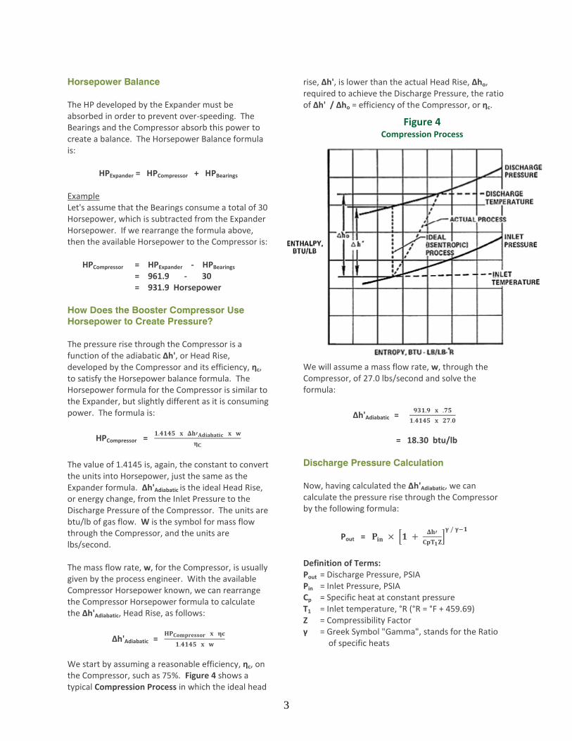
We start by assuming a reasonable efficiency, ηc, on the Compressor, such as 75%. Figure 4 shows a typical Compression Process in which the ideal head
rise, Δh', is lower than the actual Head Rise, Δho, required to achieve the Discharge Pressure, the ratio of Δh' / Δho = efficiency of the Compressor, or ηc.
We will assume a mass flow rate, w, through the Compressor, of 27.0 lbs/second and solve the formula:
Δh'Adiabatic = 𝟗𝟑𝟏.𝟗 𝐱 .𝟕𝟓
𝟏.𝟒𝟏𝟒𝟓 𝐱 𝟐𝟕.𝟎
= 18.30 btu/lb Discharge Pressure Calculation
Now, having calculated the Δh'Adiabatic, we can calculate the pressure rise through the Compressor by the following formula:
Pout = 𝐏𝐢𝐧 × [𝟏 + 𝚫𝐡′
𝐂𝐩𝐓𝟏𝐙]
𝛄 / 𝛄−𝟏
Definition of Terms: Pout = Discharge Pressure, PSIA Pin = Inlet Pressure, PSIA Cp = Specific heat at constant pressure T1 = Inlet temperature, °R (°R = °F + 459.69) Z = Compressibility Factor γ = Greek Symbol "Gamma", stands for the Ratio
of specific heats
Figure 4 Compression Process

4
To be accurate, the values of Cp, Z, and γ are best derived by a good equation of state computer program; however, for this exercise, we will assume certain values for these (T1 = 60°F, Cp = .54, Z = .98, and γ = 1.3) and solve the above formula. So, to repeat the formula for the Compressor if the Inlet Pressure equals 145 PSIA, the Discharge Pressure will be calculated:
Pout = 𝐏𝐢𝐧 × [𝟏 + 𝚫𝐡′
𝐂𝐩𝐓𝟏𝐙]
𝛄 / 𝛄−𝟏
= 𝟏𝟒𝟓 × [𝟏 + 𝟏𝟖.𝟑𝟎
.𝟓𝟒 ×(𝟔𝟎+𝟒𝟓𝟗.𝟔𝟗)× .𝟗𝟖]
𝟏.𝟑/.𝟑
= 145 x [ 1.0665 ]
4.333
= 145 x 1.322
= 191.7 PSIA How is the Turboexpander Design Speed
Determined?
This is done by using the term Specific Speed, or Ns, of the Expander Wheel:
Ns = 𝐍 𝐱 √𝐀𝐂𝐅𝐒𝟐
(𝟕𝟕𝟖 𝐱 𝚫𝐡′𝐒).𝟕𝟓
From earlier pages, Δh's = 40 btu/lb Assume a Specific Speed, Ns = 75 for good efficiency Assume, ACFS2 = 25.0 (ACFS2 is the Actual Cubic Feet per Second of volumetric flow at the outlet of the Expander). Rearrange the formula and calculate the speed, N:
N = 𝐍𝐬 × (𝟕𝟕𝟖 × 𝚫𝐡′𝐒).𝟕𝟓
√𝐀𝐂𝐅𝐒𝟐
= 𝟕𝟓 × (𝟕𝟕𝟖 × 𝟒𝟎).𝟕𝟓
√𝟐𝟓
= 𝟕𝟓 ×𝟐𝟑𝟒𝟑
𝟓
= 35,146 RPM How to Approximate the Expander Wheel
Diameter
First, for good efficiency, the term U/Co should equal about 0.7. The Co term is known as the spouting velocity of the gas from the Nozzles into the Expander Wheel. The formula is:
Co = √ 𝟐 × 𝐠 × 𝐉 × √𝚫𝐡′𝐬
= √ 𝟐 × 𝟑𝟐. 𝟐 × 𝟕𝟕𝟖 × √𝟒𝟎
= √ 𝟓𝟎𝟏𝟎𝟑. 𝟐 × √𝟒𝟎
= 𝟐𝟐𝟑. 𝟖 × √𝟒𝟎 = 1415 ft/sec Since the term U, Wheel Tip Speed, needs to be 0.7 of Co, then: U = .7 x Co
= .7 x 1415 = 990 ft/sec Definition of Terms: U = Tip Speed of Wheel, ft/sec Co = Spouting Velocity, ft/sec g = 32.2 ft/sec2 J = 778 ft-lb/btu The term, U, is the peripheral velocity of the Expander Wheel (tip speed) which is calculated by:
U = 𝐃𝐢𝐚𝐦𝐞𝐭𝐞𝐫 (𝐢𝐧𝐜𝐡𝐞𝐬) 𝐱 𝐑𝐏𝐌
𝟐𝟐𝟗.𝟐
So, to rearrange the formula to solve for the Wheel Diameter:
Diameter = 𝐔 × 𝟐𝟐𝟗.𝟐
𝐑𝐏𝐌
= 𝟗𝟗𝟎 × 𝟐𝟐𝟗.𝟐
𝟑𝟓,𝟏𝟒𝟔
= 6.46 inches
How to Approximate the Compressor Wheel
Diameter
The following formula can be used to approximate the Compressor Wheel Diameter:
Δh'Adiabatic = 𝑼𝟐× 𝚿
𝐠 × 𝐉
From previous pages, we calculated the Compressor Δh'Adiabatic to equal 18.30 btu/lb. Let the head

5
coefficient, Ψ, be equal to .4 and rearrange the formula to solve for U:
U2 =
𝜟𝒉′× 𝒈 × 𝑱
.𝟒
U = √(𝜟𝒉′× 𝒈 × 𝑱)
.𝟒
U = √(𝟏𝟖.𝟑𝟎 𝑿 𝟑𝟐.𝟐 𝑿 𝟕𝟕𝟖)
.𝟒
U = √𝟏, 𝟏𝟒𝟔, 𝟏𝟏𝟎. 𝟕 U = 1070.6 ft/sec Now calculate the Compressor Wheel Diameter from the equation:
U = 𝐖𝐡𝐞𝐞𝐥 𝐃𝐢𝐚𝐦𝐞𝐭𝐞𝐫 𝐱 𝐑𝐏𝐌
𝟐𝟐𝟗.𝟐
From the Expander analysis, the design speed was calculated to be 35,146 RPM. So rearranging and solving the above formula: Compressor Wheel diameter = dC
𝐝𝐜 =𝐔 × 𝟐𝟐𝟗. 𝟐
𝐑𝐏𝐌
𝐝𝐂 =𝟏𝟎𝟕𝟎. 𝟔 × 𝟐𝟐𝟗. 𝟐
𝟑𝟓, 𝟏𝟒𝟔
dC = 6.98 inches ** Caution Note**: While the above method does give the steps necessary to do the initial rough sizing of the Expander and Compressor Wheels, it is vastly over simplified. In the above, certain values were assumed for specific speed, efficiency, head coefficient, etc. These assumptions were used for ease of demonstrating the formulas only. These assumptions MUST NOT be used as "rule of thumb" values, as they may give false results in an actual case. Any actual design analysis should be performed by an experienced Turboexpander Design Engineer.
Turboexpander Controls, with reference to the Turboexpander system schematic drawing (Figures 5 & 6): The Turboexpander system pressure basically floats with the Compressor suction pressure. This is achieved by venting the pressurized oil Reservoir through a De-misting Pad back to the Compressor Suction.
Figure 5 P & ID 1
Figure 6 P & ID 2
6
Lube Oil System
The Lube Oil Pressure supplied to the Bearings is controlled at a pressure higher than the Reservoir, typically this pressure is 150 PSID controlled by a Differential Pressure Regulating Valve relieving excess oil to the Reservoir. Dual, Electric Motor Driven, Lube Oil Pumps (one Main and one Standby) take suction from the Reservoir providing oil through the Cooler or bypassing the Cooler via the Temperature Control Valve as required to maintain a preset oil supply temperature to the Bearings. The oil is then filtered by one of the Dual Filters. At this point the oil pressure regulates to the proper Differential Pressure. An Accumulator is installed to store oil for emergency coast down in case of electrical power outage. The oil then travels to the Bearings. Some systems have an oil flow rate measuring device in the oil supply line to the Bearings. Shaft Sealing System
The Shaft Seals are Labyrinth type using Seal (Buffer) Gas to prevent cold gas migration into the Bearing Housing and prevent oil leakage into the process stream. The Seal Gas system typically uses warm process gas that has been filtered. The pressure to the Labyrinth Seals is maintained at a Differential Pressure of typical 50 PSID above the pressure behind the Expander Wheel. This is accomplished by use of a Differential Pressure Regulator sensing and floating with the Expander Back Wheel Pressure. The small amount of Seal Gas going across the Seal towards the Bearing Housing mixes with the oil and drains to the Reservoir. In the Reservoir, this separates from the oil and then is vented through the De-misting Pad out into the Booster Compressor Suction. Basically, the Turboexpander System Pressure automatically floats with the process pressure via the Compressor Suction. For control of the Turboexpander at start-up, a local Hand Indicating Controller (HIC) is provided to adjust the Expander variable Nozzles to control the Gas Flow (and Expander Speed) during start-up. Primary safety instrumentation includes Speed Probe, Vibration Probe, Bearing Temperature RTDs,
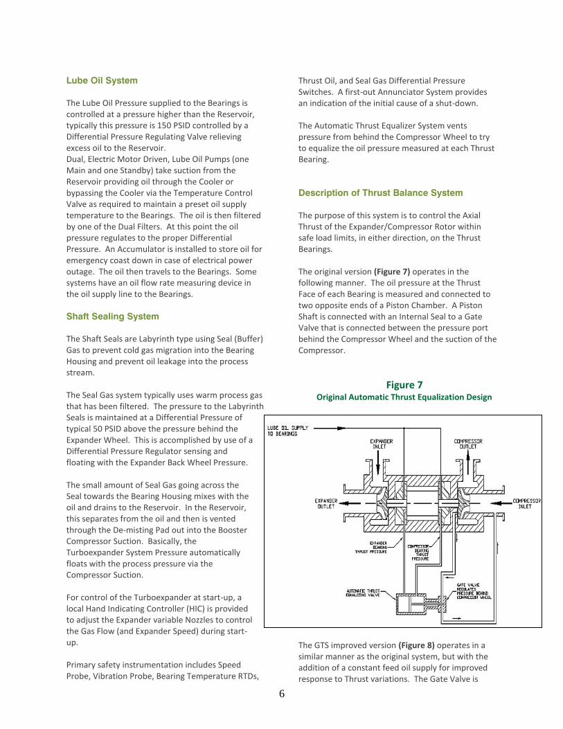
Thrust Oil, and Seal Gas Differential Pressure Switches. A first-out Annunciator System provides an indication of the initial cause of a shut-down. The Automatic Thrust Equalizer System vents pressure from behind the Compressor Wheel to try to equalize the oil pressure measured at each Thrust Bearing. Description of Thrust Balance System
The purpose of this system is to control the Axial Thrust of the Expander/Compressor Rotor within safe load limits, in either direction, on the Thrust Bearings. The original version (Figure 7) operates in the following manner. The oil pressure at the Thrust Face of each Bearing is measured and connected to two opposite ends of a Piston Chamber. A Piston Shaft is connected with an Internal Seal to a Gate Valve that is connected between the pressure port behind the Compressor Wheel and the suction of the Compressor.
The GTS improved version (Figure 8) operates in a similar manner as the original system, but with the addition of a constant feed oil supply for improved response to Thrust variations. The Gate Valve is
Figure 7 Original Automatic Thrust Equalization Design

7
replaced by a "balanced piston" Spool Valve, which is less prone to sticking (less resistance) than the Gate Valve, and therefore more responsive. The Spool Valve is connected between the pressure vent port behind the Compressor Wheel and the suction of the Compressor, just as the original system.
The Thrust balancing is accomplished by maintaining or decreasing the pressure behind the Compressor Wheel. This is accomplished when the Thrust force (oil pressure) on the Compressor Thrust Bearing is increased, which causes the Piston to slowly open the Spool Valve, thereby reducing the pressure in the area behind the Compressor Wheel causing the load on the Compressor Thrust Bearing to reduce. The opposite occurs when the load is increased toward the Expander Thrust Bearing. In turn, the Spool Valve will tend to close. With the GTS version, the end of the Thrust Equalizing Valve can be viewed and verified as to which direction the Thrust Valve is in. Description of Surge Control System
The Surge Condition The phenomenon of “surge” in an axial or centrifugal Compressor occurs when the flow is reduced sufficiently to cause a momentary reversal of flow. This reversal tends to lower the pressure in the discharge line. Normal compression resumes, and the cycle is repeated. This cycling, or surging, can
vary in intensity from an audible rattle to a violent shock. Intense surges are capable of causing complete destruction of the components in the Compressor such as Blades, Bearings, and Seals. An Anti-Surge Control system is therefore recommended to provide positive protection against surging or cycling. Flow Relation in the Compressor
The performance map of the Compressor, typically supplied by the Compressor manufacturer, is a plot of Pressure increase (head) vs. Capacity (flow) over the full range of operating conditions. At any given Compressor speed, a point of maximum discharge pressure is reached as the flow is reduced. This is indicated at points A, B, C, D, E, and F in Figure 9 below. The line connecting these points describes the surge limit line, which separates the region of safe operation from the surge area.
As flow is reduced, the pressure in the Compressor tends to be lower than the discharge pressure and a momentary reversal of flow occurs. This reversal then tends to lower the pressure at the discharge, allowing for normal compression until the cycle repeats itself.
Figure 8 Improved Automatic Thrust Equalization
Design
Figure 9 Performance Map of the Compressor

8
Surge Control
The most common method of Surge Control uses the Compressor ∆P to represent “head” and the differential pressure across an Inlet orifice (called “h”) to represent capacity. The function of the Surge Control system is to keep the ratio of ∆P/h from exceeding the slope of the surge line. To provide some factor of safety, a control line (Set Point) should be established to the right of the surge line, as shown in Figure 10 below.
A typical anti-Surge control system block diagram is shown on the attached sketch, Figure 11. In operation, the Inlet Flow is measured differentially through an Orifice plate using a DP Transmitter, with its output connected to a Ratio Station (multiplier) and then transmitted as a set point to the Controller (PID). The Inlet and Discharge pressures of the Compressor are also measured using a DP Transmitter and transmitted as the Process variable to the Controller. The output of the Controller operates a bypass valve that recycles the gas back to the Inlet of the Compressor. In general, when the two (2) signals become equal within the bounds of the Proportional
Band range, the Controller will output a signal to open the Bypass (Recirculation) Valve. If the Flow rate is too low (i.e., near surge) then the Bypass Valve should open and allow additional flow to re-circulate back to the Compressor as necessary. In normal operation, the Bypass Valve is closed to prevent pressure losses and it opens only to prevent surge.
Figure 10
Surge Control
Figure 11 Anti-Surge Control System