FUNDAMENTALS OF SOL-GEL DIP COATING · I. INTRODUCTION In its simplest manifestation, sol-gel dip...
12
Thin Solid Films, 201 (1991) 97 108 PREPARATION AND CHARACTERIZATION 97 FUNDAMENTALS OF SOL-GEL DIP COATING C. J. BRINKER, G. C. FRYE, A. J. HURD AND C. S. ASHLEY Sandia National Laboratories, Albuquerque. NM 87185-5800 ( U.S.A. ) Received June 6, 1990; accepted January 7, 199l) During sol-gel thin film formation via dipping, polymeric or particulate inorganic precursors are concentrated on the substrate surface by a complex process involving gravitational draining with concurrent drying and continued conden- sation reactions. The structure of films deposited from polymeric precursors depends on such factors as size and structure of the precursors, relative rates of condensation and evaporation, capillary pressure, and substrate withdrawal speed. Using polymeric silicate precursors, the porosity and refractive index of the deposited films may be varied as follows: volume percent porosity (0%-56%); pore radius (0-3.1 nm); surface area (1.2-263 m2g l); refractive index (1.18-1.45). For repulsive, monosized particulate precursors, higher coating rates promote ordering of the particles as manifested by a reduction in porosity from 36~/o (random dense packing) to about 25% 0 (f.c.c. or h.c.p.), I. INTRODUCTION In its simplest manifestation, sol-gel dip coating consists of the withdrawal of a substrate from a fluid sol: gravitational draining and solvent evaporation, accom- panied by further condensation reactions, result in the deposition of a solid film. Compared with conventional thin film forming processes such as chemical vapor deposition, evaporation, or sputtering, sol-gel dip coating requires considerably less equipment and is potentially less expensive. However, the most important advantage of sol-gel over conventional coating methods is the ability to tailor the microstructure of the deposited film. In this communication we first review the elementary physics and chemistry accompanying sol-gel dip coating. We then summarize how varying the precursor structure, solvent composition, or deposition conditions can affect the microstructure of the deposited films. Structural inform- ation is obtained from thin film samples in situ, using techniques such as imaging and conventional ellipsometry, small angle X-ray scattering (SAXS), and gas adsorption-desorption on sol-gel-coated surface acoustic wave (SAW) sensors. 0040-6090//91/$3.50 ~C: Elsevier Sequoia/Printed in The Netherlands
Transcript of FUNDAMENTALS OF SOL-GEL DIP COATING · I. INTRODUCTION In its simplest manifestation, sol-gel dip...

Thin Solid Films, 201 (1991) 97 108
PREPARATION AND CHARACTERIZATION 97
FUNDAMENTALS OF SOL-GEL DIP COATING
C. J. BRINKER, G. C. FRYE, A. J. HURD AND C. S. ASHLEY
Sandia National Laboratories, Albuquerque. N M 87185-5800 ( U.S.A. )
Received June 6, 1990; accepted January 7, 199l)
During sol-gel thin film formation via dipping, polymeric or particulate inorganic precursors are concentrated on the substrate surface by a complex process involving gravitational draining with concurrent drying and continued conden- sation reactions. The structure of films deposited from polymeric precursors depends on such factors as size and structure of the precursors, relative rates of condensation and evaporation, capillary pressure, and substrate withdrawal speed. Using polymeric silicate precursors, the porosity and refractive index of the deposited films may be varied as follows: volume percent porosity (0%-56%); pore radius (0-3.1 nm); surface area (1.2-263 m2g l); refractive index (1.18-1.45). For repulsive, monosized particulate precursors, higher coating rates promote ordering of the particles as manifested by a reduction in porosity from 36~/o (random dense packing) to about 25% 0 (f.c.c. or h.c.p.),
I. INTRODUCTION
In its simplest manifestation, sol-gel dip coating consists of the withdrawal of a substrate from a fluid sol: gravitational draining and solvent evaporation, accom- panied by further condensation reactions, result in the deposition of a solid film. Compared with conventional thin film forming processes such as chemical vapor deposition, evaporation, or sputtering, sol-gel dip coating requires considerably less equipment and is potentially less expensive. However, the most important advantage of sol-gel over conventional coating methods is the ability to tailor the microstructure of the deposited film. In this communication we first review the elementary physics and chemistry accompanying sol-gel dip coating. We then summarize how varying the precursor structure, solvent composition, or deposition conditions can affect the microstructure of the deposited films. Structural inform- ation is obtained from thin film samples in situ, using techniques such as imaging and conventional ellipsometry, small angle X-ray scattering (SAXS), and gas adsorption-desorption on sol-gel-coated surface acoustic wave (SAW) sensors.
0040-6090//91/$3.50 ~C: Elsevier Sequoia/Printed in The Netherlands

98 C. J. BRINKER, G. C. FRYE, A. J. HURD~ C. S. ASHLEY
2. PHYSICS AND CHEMISTRY OF SOL--GEL DIP COATING
2.1. Precursor sol The sol gel process 1 uses inorganic or metal organic compounds as raw
ingredients. In aqueous or organic solvents these compounds are hydrolyzed and condensed to form inorganic polymers composed of M - - O - - M bonds. For inorganic compounds, hydrolysis proceeds by the removal of a proton from an aquo ion [MONH2,~] -'+ to form a hydroxo ( M - - O H ) or oxo ( M = O ) ligand. Condensa- tion reactions involving the hydroxo ligands result in inorganic polymers in which metal centers are bridged by oxygens or hydroxyls. The most commonly used metal organic compounds (the subject of this paper) are metal alkoxides M(OR):, whcre R is an alkyl group CxH2x + 1- Normally the alkoxide is dissolved in alcohol and hydrolyzed by the addition of water under acidic, neutral, or basic conditions. Hydrolysis results in the replacement of an alkoxide with a hydroxyl ligand:
M(OR): + H 2 0 -~ M(OR)~ _ 1OH + R O H (1)
Condensation reactions involving the hydroxyl ligands produce M - - O - - M (or M - - O H - - M ) bonds as shown below for silicates:
Si(OR)3OH + Si(OR)4 -~ (RO)3Si--O--Si(OR)3 + ROH (2)
2Si(OR)3OH ~ (RO)3Si--O--Si(OR) 3 + H20 (3)
Depending on the synthesis procedure, e.g. pH or the molar ratio r of H20 :M in eqn. (1), the structures of the inorganic polymers may vary considerably. Previous work on silicates 2'3 has shown that condensation results in a spectrum of structures ranging from weakly branched polymers characterized by a mass fractal dimension to highly condensed uniform particles. The mass fractal dimension D relates the polymer mass M to its radius r according to
M ~z r ° (4)
where D is less than the dimension d of space. Since in three dimensions D < 3, the density of a mass fractal object decreases radially as 1/r 3-D. As we will show, this feature permits us to tailor the film porosity by a simple aging procedure.
2.2. Dip coating In dip coating, the substrate is normally withdrawn vertically from the liquid
bath at a speed Uo (Fig. l(a)). The moving substrate entrains the liquid in a fluid mechanical boundary layer that splits in two above the liquid bath surface, the outer layer returning to the bath 4 (see Fig. l(b)). Since the solvent is evaporating and draining, the fluid film terminates at a well-defined drying line (x = 0, in Fig. l(a)). When the receding drying line velocity equals Uo, the process is steady state with respect to the liquid bath surface. A non-constant evaporation rate in the vicinity of the drying line (due to geometrical factors affecting the diffusion of solvent vapor from the liquid surface) results in a parabolic thickness profileS:
h(x) ~ x 1/2 (5t
where h(x) is the film thickness as a function of position x below the drying line.

SOL--GEL DIP COATING 99
SOL-GEL DIP-COATING
K
T Uc
DEPOSITED / pressure FILM exerted at final
I stage of dwing x = 0 as menisci
FILM COLLAPSE AND/ recede into get interior
OR PORE FORMATION Cp = 2"(i.¥ cos(0)
GELATION ~ ~ r
ALCOHOLPNATER EVAPORATION
AGGREGATION
GRAVITATIONAL DRAINING
÷ EVAPORATION
F
(a)
U
I .
W S
i
~,~ {r I Uo) 2/3/YLV 1/6(p g) 1/2 ENTRAINED DILUTE SOL
V RESERVOIR SURFACE
DILUTE SOL
PORE SIZE CONTROLLED BY:
- SIZE, STRUCTURE, COMPOSITION
- RATES OF CONDENSATION/ EVAPORATION
- CAPILLARY PRESSURE
LIQUID BATH
SURFACE
I I
5 {b) Fig. 1. (a) Schematic diagram of the steady state dip coating process, showing the sequential stages of structure development that result from draining accompanied by solvent evaporation and continued condensation reactions. (b) Detail of liquid flow patterns during dip coating. U is the withdrawal speed, S is the stagnation point, 6 is the boundary layer, and h is the thickness of the fluid film.
In an excellent review of dip coating, Scriven 4 states that the thickness of the deposited film is related to the position of the streamline dividing the upward and downward moving layers. A competition between as many as six forces in the film deposition region governs the film thickness and position of the stream line 4. When the liquid viscosity r/and substrate speed Uo are high enough to lower the curvature of the meniscus, the deposited film thickness h is that which balances the viscous
100 C. J. BRINKER, G. C. FRYE, A. J. HURI), C. S. ASHLEY
drag (proportional to q Uo/h) and gravity force (pgh)'*'6:
h = ct(r 1U0/pg) t/2 (6)
where the constant c~ is about 0.8 for ncwtonian liquids. When the substrate speed and viscosity are low (often the case for sol gel film deposition), this balance is modulated by the ratio of viscous drag to liquid-vapor surface tension 7Lv according to the relationship derived by Landau and LevichT:
h = 0.94(q Uo)2/3/YLV1/6(p~r)l/2 (7)
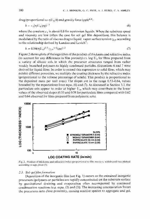
Figure 2 shows plots of the logarithm of the product of thickness and refractive index (to account for any differences in film porosity) vs. log Uo for films prepared from a variety of silicate sols in which the precursor structures ranged from rather weakly branched polymers to highly condensed particles. (Equations 6 and 7 were derived for liquid fihns. In order to extend this expression to solid films, which may exhibit different porosities, we multiply the coating thickness by the refractive index (proportional to the volume percentage of solids). This product is proportional to the deposited mass per unit area.) The slopes are in the range 0.53-0.64, values bounded by the expectations from eqns. (6) and (7). As discussed in Section 3.3, the particulate sols appear to order at higher Uo, which may contribute to the lower values of the observed slopes (0.53 and 0.58 for particulate films compared with 0.62 and 0.64 observed for films prepared from polymeric sols).
X IJ.I 0 Z
t.t)
ILl Z v
I-
0 . J
10000 i
1000
100
SLOPE • STRONGLY BRANCHED (0.62) [ ] WEAKLY BRANCHED (0.64) O PARTICULATE 95 nm (0.53) • PARTICULATE 72 nm (0.58)
I
10
L O G C O A T I N G R A T E ( i n / m i n )
Fig. 2. Producl of thickness and refractive index (proportional to film mass) vs. withdrawal rate plotted according to eqn. (6) or (7).
2.3. Sol gel.t~Tm formation Deposition of the inorganic film (see Fig. 1) occurs as the entrained inorganic
precursors (polymers or particles) are rapidly concentrated on the substrate surface by gravitational draining and evaporation often accompanied by continued condensation reactions (e.g. eqns. (2) and (3)). The increasing concentration forces the precursors into close proximity, causing reactive species to aggregate and gel,

SOL--GEL D I P C O A T I N G 101
while repulsive particles appear to assemble into liquid- or crystal-like structures depending on the withdrawal rate (see Section 3.3). For reactive precursors a competition is established between solvent evaporation which compacts the structure and continuing condensation reactions which stiffen the structure, increasing its resistance to compaction. Unlike conventional bulk gel formation, the drying stage overlaps the aggregation-gelation stages, establishing only a brief time span (several seconds) for condensation reactions to occur. A common result is rather compliant structures that are collapsed at the final stage of drying by the capillary pressure P created by the liquid-vapor menisci as they recede into the film interior:
P = 27L v Cos(O)/r (8)
where 0 is the wetting angle and r is the hydraulic radius of the pore at the moment the meniscus recedes into the gel interior. Because r may be very small (less than 1.0 nm) ~, P may exceed 60 MPa even for liquids with low surface tensions such as ethanol (TLv = 23 dynes cm- t).
The draining and evaporation which accompany dipping (Fig. l(a)) cause the thickness h and volume fraction ~b of solids of the depositing film to change continuously with distance above the liquid bath surface. Above the stagnation point (see Fig. l(b)) where all fluid elements are moving upward, steady state conditions require that the solids mass in any horizontal slice must be constant:
h(x)d)(x) = constant (9)
so ~b varies inversely with h in the thinning film. Since for a planar substrate there is a parabolic thickness profile 4 (h(x) ~ xl/2), q~ should vary as 1/h ~ x 1,2 (ref. 5).
3. C O N T R O L OF FILM M I C R O S T R U C T U R E
From the brief description of sol-gel dip coating presented above, it seems obvious that the structure of the depositing "film will be sensitive to a variety of factors such as polymer (or particle) size, structure, and reactivity, relative rates of condensation and evaporation, liquid surface tension, and dipping speed. In this section we document how these factors influence fihn structure with the goal of preparing inorganic thin films with tailored porosities. We rely on imaging ellipsometry s to characterize the steady state dip coating process and conventional ellipsometry combined with gas adsorption-desorption measurements using SAW techniques 9 to determine the structural features of the deposited film.
3.1. Influence o f precursor structure and reactivity The possible structures of the inorganic precursors range from weakly
branched polymers to high condensed particles. For fractal objects the packing efficiency (i.e. the solids volume fraction q~) depends on the fractal dimension, size, and condensation rate. The fractal dimension and size dictate steric constraints. Mandelbrot i 0 has shown that if two structures of radius R are placed independently in the same region of space, the mean number M 1.2 of intersections is expressed as:
m1,2 0C R °' +o2-d (10)

102 C . J . BRINKER, G. C. FRYE, A. J. HURD, C. S. ASHLEY
where Dt and D 2 a r e the corresponding fractal dimensions and d is the dimension of space (d = 3). Thus if each object has a fractal dimension less than 1.5, the probability of intersection decreases indefinitely as R increases. These structures are mutually transparent: during film formation, they freely interpenetrate as they are forced into close proximity by the increasing concentration. Alternatively, if the fractal dimension of each object exceeds 1.5, the probability of intersection increases algebraically with R, The structures, although porous, are mutually opaque; when concentrated they are unable to interpenetrate, much like an assemblage of "tumbleweeds".
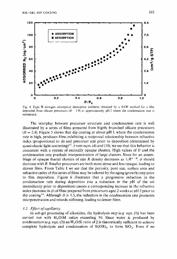
These concepts of mutually opacity or transparency assume that every intersection results in irreversible "sticking"; conditions chemically equivalent to an infinite condensation rate. In fact, the condensation rates of silicates are quite low (e.g. 10 4 1 mol - [ s 1)1t and very dependent on [H +] 12.[3 (Fig. 3). Thus the probability of sticking at any point of intersection is much less than 1, causing film structures to be generally more compact than expected from eqn. (10). For example, deposition of weakly branched silicate sols (D = 1.9) near pH2, where the condensation rate is minimized (Fig. 3), produces dense films characterized by a type II N 2 adsorpt ion-desorpt ion isotherm 14 (Fig. 4) and surface area equivalent to the geometric area of the film 9. This indicates that there is no porosity accessible to molecules 0.4 nm or morc in diameter. Because the condensation rate is low under these conditions, we expect that, although D > 1.5, the precursors can interpenetrate as they are concentrated on the substrate surface by evaporation, leading to densely packed configurations with molecular-scalc porcs. During thc final stage of drying the capillary pressure is enormous because of the small pores (eqn. (8)), causing further compaction of the compliant precursors.
?
n.-
z _ = O ~ p _ >
z ~
ILl >
I I I 1 I I I I I
I I I • p-~s~ Ji I I * H.o3
UJ B i i i I I I i t I
0 1 2 3 4 5 6 7 8
pH Fig. 3. Average condensation rate l / t ~ I vs. pH for tetraethylorthosilicate hydrolyzed with 4 equivalents of water (based on data of Coltrain et al . a 3). A and B correspond to regions of higher and lower sticking probability respectively.
SOL-GEL DIP COATING 103
120
100
E o 80
• ADSORPTION • DESORPTION
; ~ 6O
4o
~< 2o
• • • •
i n l n U O • N N I • o c O O 0
anmo O O • I I : o
nno o •-'.""'""
| !
• o • g
O I I I I I I I I I 0
0 0.2 0.4 0.6 0.8 1.O
P/Po
8.4
7.0
5.6 a. I.- (n
4.2 . ~ e) E o
2.8 ' ~
1.4
Fig. 4. Type II nitrogen adsorption~desorption isotherm obtained by a SAW method for a film deposited from silicate precursors (D = 1.9) at approximately pH 2 where the condensation rate is minimized.
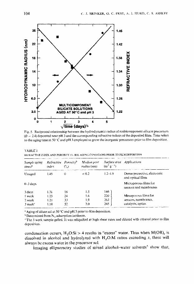
The interplay between precursor structure and condensation rate is well illustrated by a series of films prepared from highly branched silicate precursors (D = 2.4). Figure 5 shows that dip coating at about pH 3, where the condensation rate is high, produces films exhibiting a reciprocal relationship between refractive index (proportional to 4)) and precursor size prior to deposition (determined by quasi-elastic light scattering) 15. From eqns. (4) and (10), we see that this behavior is consistent with a system of mutually opaque clusters. High values of D and the condensation rate preclude interpenetration of large clusters. Since for an assem- blage of opaque fractal clusters of size R density decreases as 1/R 3-D, (a should decrease with R. Smaller precursors are both more dense and less opaque, leading to denser films. From Table I we see that the porosity, pore size, surface area and refractive index of this series of films may be tailored by the aging (growth) step prior to film deposition. Figure 6 illustrates that a progressive reduction in the condensation rate during deposition (via a reduction in the pH of the sol immediately prior to deposition) causes a corresponding increase in the refractive index (increase in 4)) of films prepared from precursors aged 2 weeks at pH 3 prior to dip coating 16. Although D >> 1.5, the reduction in the condensation rate promotes interpenetration and retards stiffening, leading to denser films.
3.2. Effect of capillarity In sol-gel processing of alkoxides, the hydrolysis step (e.g. eqn. (1)) has been
carried out with H20:M ratios exceeding 50. Since water is produced by condensation (e.g. eqn. (3)) an H20:Si ratio of 2 is theoretically sufficient to achieve complete hydrolysis and condensation of Si(OR) 4 to form SiO2. Even if no
104 C . J . B R I N K E R , G . C. F R Y E , A. J. H U R D , C. S. A S H L E Y
E c
I
a <
o m
5 < Z >- I:1 0
Q >. " r
26
22
18
14
10
°° f 2.0
o ! . 0
I I I I 1
e
MULTICOMPONENT SILICATE SOLUTIONS
AGED AT 50°C and pH 3
1 2 3 4 5
(nays)',,
1.46
1.42
X I¢I
1.38 £3 Z m
w >
1.34 I .- O < ¢C
1,30 I.I. I¢I
1.26
1,22
Fig. 5. Reciprocal relationship between the hydrodynamic radius ofmulticomponent silicate precursors (D = 2.4 deposited near pH 3 and the corresponding refractive indices of the deposited films. Time refers to the aging time at 50 ':C and pH 3 employed to grow the inorganic precursors prior to film deposition.
TABLE I REFRACTIVE INDEX AND POROSITY t),% SIS)I, AGING CONDITIONS PRIOR TO FILM DEPOSITION
Sample aging Refractive Porosity b Median pore Surface area Applications times" index (°~i) radius (nm) (m 2 g- l)
Unaged 1,45 0 < 0.2 1.2 1.9
0-3 days
Dense protective, electronic and optical films
Microporous films for sensors and membranes
3 days 1.31 16 1.5 146 ) ..ok , 6 2 week 1.21 33 1.9 i sensors, membranes. 3 week c 1.18 52 3.0 245 J catalysts, optics
"Aging of dilute sol at 50 ~'C and pH 3 prior to film deposition. b Determined from N2 adsorption isotherm. ~Tfie 3 week sample gelled. It was reliqaified at high shear rates and diluted with ethanol prior to film deposition.
c o n d e n s a t i o n occurs , H 2 0 : S i > 4 resul ts in "excess" water . T h u s w h e n M(OR)~ is d i s so lved in a l c o h o l and h y d r o l y z e d wi th H e O : M ra t ios exceed ing z, t he re will
a lways be excess w a t e r in the p r e c u r s o r Sol. I m a g i n g e l l i p s o m e t r y s tudies of m i x e d a l c o h o l - w a t e r so lven t s 5 s h o w that ,

SOL--GEL DIP COATING 105
1 .39 L,,= I I 1 . 24
1 .37 I - T - 5 . 7 6
1 . 3 5 - 1 0 . 3 4 tU IJJ " =Z
Z 1 .33 C H A N G I N G n WITH A D D I T I O N S - 1 4 . 9 9 :~ 1.1.1 2 M HCI . . I _ O ~> C H A N G I N G n I-- 1 . 31 WITH E Q U I V A L E N T - 1 9 . 7 0 IJ.I
,c¢ A D D I T I O N S OF H 2 0 n- " _ O
I.I. 1 . 2 9 • - 2 4 . 4 8 a . U.I
1 .27 - 2 9 . 3 1
1 .25 3 4 . 2 1 1 2 3 4
p H
Fig. 6. Refractive index and pore volume of films prepared from mult icomponent silicate precursors (D = 2.4) v s . the deposition pH. pH was adjusted from an initial value of 3.2 by addition of 2 M HCI. Changes in the refractive index caused by equal volumes of water are indicated.
during dip coating, the mixture becomes enriched in water in the vicinity of the drying line. This water enrichment occurs even at the azeotropic mixture, apparently by preferential evaporation of alcohol and/or surface tension gradient driven flows. One consequence of water enrichment near the drying line during sol deposition is an increase in the capillary pressure (due to the greater surface tension of water) during the final stage of drying as l iquid-vapor menisci recede into the film interior (eqn. (8)). Assuming complete wetting (4) = 0 ° in eqn. (8)), the maximum increase in P would be a factor of about 3.
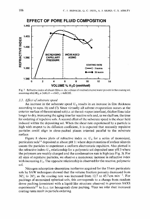
In order to evaluate the effect of water enrichment on the structure of the deposited film, we prepared silicate sols in which excess water was varied from about 0.5 to 10.5 vol.% (assuming complete hydrolysis and condensation). The refractive index of the deposited films increased from 1.342 to 1.431 as the excess water was increased from 0.5 to 6 vol .~ (Fig. 7), corresponding to a reduction in porosity from 22~/o to 7~o. Further increases in the excess water caused a reduction in refractive index (increase in porosity). We believe that this behavior reflects the competition between capillary pressure and aging (stiffening) of the silicate skeleton, which are both enhanced by the increasing water concentrations. These results differ from those of Glaser and Pantano t7 who observed a monotonic increase in refractive index with water concentration for spin-coated silicate films. The difference between dip and spin coating is the evaporation rate and correspondingly the time available for aging. Spinning creates a strong forced convection in the vapor above the substrate 4, increasing the evaporation rate. Thus there is little time for aging to occur and the structure of the film is dominated by the effects of capillarity.
106 •. J. BRINKER, G. C. FRYE, A. J. HURD, C. S. ASHI.EY
EFFECT OF PORE FLUID COMPOSITION 1.440 i I I I I i
_z I~1 1.400 _> I-- / INCREASING INCREASED L) < 1.380 / CAPILLARY AGING u.n" / PRESSURE
LU ~ COATING RATE n" 1.360 ~ O ~ O 2 In/rain
Q ~ O 20 Inlmin
1.340 O I I I t I I 0 2 4 6 8 10 12 14
V O L U M E % H 2 0 ( r e s i d u a l ) Fig. 7. Refractive index of silicate films ws. the volume of residual(excess)water present in the coating sol, assuming nSi(OR)4 + 2nil 20 --+ nSiO 2 + 4nROH.
3.3. Effect o f substrate speed An increase in the substrate speed U o results in an increase in film thickness
according to eqns. (6) and (7). Since virtually all solvent evaporation occurs at the exterior surface of the entrained sol (i.e. at the sol-vapor interface), thicker films take longer to dry, increasing the aging time for reactive sols and, as we shall see, the time for ordering of repulsive sols. A second effect of the substrate speed is the shear field induced within the depositing sol. When the shear rate experienced by a particle is high with respect to its diffusion coefficient, it is expected that mutually repulsive particles could align in close-packed planes oriented parallel to the substrate surface.
Figure 8 shows plots of refractive index vs. U o for a series of monosized, particulate sols ~ ~ deposited at about pH 11 where deprotonation of surface silanols causes the particles to experience a uniform electrostatic repulsion. Also plotted is the refractive index-Uo relationship for a polymeric sol deposited near pH 3 where the polymers are weakly charged and the condensation rate is high (see Fig. 3). For all sizes of repulsive particles, we observe a monotonic increase in refractive index with increasing Uo. The opposite relationship is observed for the reactive, polymeric sol.
Nitrogen adsorption-desorption isotherms acquired for the 55 nm particulate sols by SAW techniques showed that the volume fraction porosity decreased from 36~Uo to 26~/o as the coating rate was increased from 12.7 to 45.7 cm rain-~. For packings of monosized spherical sols, this corresponds to a change from random dense packing (consistent with a liquid-like structure observed in previous SAXS experiments is to f.c.c. (or hexagonal) close packing. Thus we infer that increased coating rates result in particle ordering.

SOL--GEL DIP COATING 107
1 . 3 5 0 I l I I I i I
1 . 3 o o
" A 5 5 nm
~C • P O L Y M E R
[ ]
1 . 1 5 0 I I I I I I
0 5 10 15 2 0 2 5 3 0 3 5
COATING RATE (in./mln) Fig. 8. Refractive index vs. withdrawal speed for silicate films deposited from repulsive, monosized, particulate sols at approximately pH 11 compared with that for films prepared from reactive polymeric sols at approximately pH 3.
The smooth increase in refractive index with U 0 argues against a discrete phase transition from a liquid-like to a crystal-like structure. Experiments on monosized, spherical colloids 18, however, indicate such a transition at q~ ~ 0.3 and a P6clet number Pe ~ 1 where
Pe = va2/Do (11)
and v (s- 1) is the shear rate, a (cm) is the particle diameter, and Do (cm 2 s- 1) is the diffusion coefficient. For 55 nm diameter particles deposited at 45.7 cm rain- 1 from a low viscosity alcohol-based sol, Pe ~ 0.04 near the liquid bath surface where v is maximized (about 275 s - 1). However, during dipping 4) varies inversely with h (eqn. (9)), greatly exceeding q~ = 0.3 near the drying line. The accompanying increase in viscosity causes a reduction in D o and therefore an increase in Pc. Thus, although the shear rate is low near the drying line, the P6clet number may be maximized there as a result of the high viscosity. The combined effects of large Pe and large ~b in the vicinity of the drying line may be responsible for the apparent ordering. We note that preliminary light scattering experiments have not provided any direct evidence of ordering within the depositing sol' 9, although we may not have the necessary spatial resolution to acquire data sufficiently close to the drying line.
A second consequence of increased withdrawal speeds is increased drying time. Increased time may benefit the ordering of repulsive particles, because finite time is required for alignment and registration of the particles into a crystal-like structure. Conversely, for the reactive sol, increased drying times caused increased stiffening of the silicate skeleton (aging) prior to the final stage of drying, leading to more porous films. In both cases the coating rate can be used to tune the porosity of the deposited film.

108 C. J. BRINKER, G. C. FRYE, A. J. HURD, C. S. ASHLEY
4. SUMMARY
During sol-gel dip coating, inorganic precursors are rapidly concentrated on the substrate surface by gravitational draining with concurrent evaporation and condensation reactions. We have presented examples of several factors that influence the structure of the deposited films: (1) size and opacity of fractal precursors; (2) relative rates of condensation and evaporation; (3) capillary pressure; (4) substrate withdrawal speed. By control of these factors it is possible to tailor the pore size, surface area, pore volume and refractive index of the deposited film. Experiments on repulsive, particulate precursors suggest particle ordering at high substrate withdrawal speeds; however, the ordering mechanism is at present not well understood.
REFERENCES
1 C.J . Brinker and G. W. Scherer, Sol-Gel Science, Academic Press, San Diego, CA, 1990. 2 D . W . Schaefer and K. D. Keefer, in C. J. Brinker, D. E. Clark and D. R. Ulrich (eds.), Better
Ceramics Through Chemistry, Elsevier, New York, 1984, pp. 1 14. 3 C.J. Brinker, K.D. Keefer, D W . Schaefer, R.A. Assink, B.D. KayandC. S. Ashley, J. Non-Cryst.
Solids, 63 (1984) 45 59. 4 L . E . Scriven, in C. J. Brinker, D. E. Clark and D. R. Ulrich (eds.), Better Ceramics Through
Chemistry 111, Materials Research Society, Pittsburgh, PA, 1988, pp. 717 729. 5 A.J . Hurd, in H. Bengna (ed.), The Colloidal Chemistry of Silica (ACS Adv. in Chem. Series) lo be
published. 6 R .P . Spiers, C. V. Subaram and W. L. Wilkinson, Chem. Eng. Sci., 29 (1974) 389-396. 7 L .D. Landau and B. G. Levich, Acta Physiochim. U.R.S.S., 17 (1942) 42 54. 8 A.J. HurdandC. J. Brinkev, J. Phys.,49(1988) lO17 1025. 9 G .C . Frye, A..1. Ricco, S. J. Martin and C. J. Brinker, in C. J. Brinker, D. E. Clark and D. R. Ulrich
(eds.), Better Ceramics Through Chemistry IH, Materials Research Society, Pittsburgh, PA, 1988, pp. 349 354. G. C. Frye, S. J. Martin, A. J. Ricco and C. J. Brinker, A CS Symp. Ser. 403 (1989) 208.
10 B.B. Mandelbrot, The Fractal Geometry o/`Nature, Freeman, San Francisco, CA, 1982. 11 M. F. Bechtold, W. Mahler and R. A. Schunn, J. Polym. Sci., Polym. Edn.,18 (1980) 2823. 12 R . K . ller, The Chemistry of Silica, Wiley, New York, 1978. 13 B.K. Coltrain, S. M. Melpolder and J. M. Salva. in D. R. Uh lmann and D. R. Ulrich (eds.), Proc.
IVth Int. ('on/'. on Ultrastructure ProcesshN of Glasses. ('eramics, and Composites, Tucson, AZ, February 19-24, 1989, Wiley, New York, to be published.
14 S.J. Grcgg and K. S. W. Sing, Adsorption, Surface Area, and Porosity, Academic Press, New York, 1982.
15 C.J. Brinker, A. J. Hurd and K. J. Ward, in J. D. Mackenzie and D. R. Ulrich (eds.), UItrastructure Processing of Advanced Ceramics, Wiley, New York, 1988, p. 223.
16 C.J . Brinker, G. C. Frye, A. J. Hurd, K. J. Ward and C. S. Ashley, in D, R. Uh lmann and D. R. Ulrich (eds.), Proc. lVth Int. Con~ on UItrastructure Processing ~?f Glasses, Ceramics and Composites, Tucson, AZ, February 19-24, 1989, Wiley, New York, to be published.
17 P .M. Glaser and C. G. Pantano, J. Non-Cryst. Solids, 63 (1984) 209 221. 18 B.J. Ackerson, J. Rheol.,34(1990) 553. 19 A. J . Hurd and C. J. Brinker, unpublished results.