Fundamentals of Pulse Heated Reflow Soldering
19
1/19 “Pulse Heated Reflow Soldering is a process where two pre-fluxed, solder coated parts are heated to a temperature sufficient to cause the solder to melt and flow, and then cooled under pressure, to form a permanent electro-mechanical bond between the parts and solder.” Fundamentals of Pulse Heated Reflow Soldering Goal: Heat the solder to 400 C above melting point temperature for 2-3 seconds to achieve proper wetting and flow. REFLOW HEAD Equipment THERMODE POWER SUPPLY (CONTROL UNIT) TOOLING A thermode is used to apply heat and pressure over a specific time/temperature profile. Temperature feedback is provided by a thermocouple:
Transcript of Fundamentals of Pulse Heated Reflow Soldering

1/19
“Pulse Heated Reflow Soldering is a process where two pre-fluxed, solder coated parts are heated to a temperature sufficient to cause the solder to melt and flow, and then cooled under pressure, to form a permanent electro-mechanical bond between the parts and solder.”
Fundamentals of Pulse Heated Reflow Soldering
Goal: Heat the solder to 400 C above melting point temperature for 2-3 seconds to achieve proper wetting and flow.
ReFlow Head
equipmentTHeRmode PoweR SuPPly
(ConTRol uniT)
Tooling
A thermode is used to apply heat and pressure over a specific time/temperature profile. Temperature feedback is provided by a thermocouple:
2/19
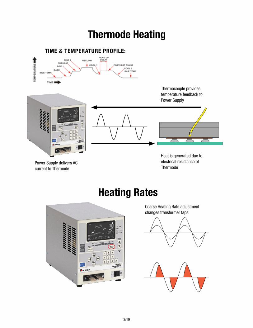
Time & TemPeRaTuRe PRoFile:
Thermode Heating
Thermocouple provides temperature feedback to Power Supply
Power Supply delivers AC current to Thermode
Heat is generated due to electrical resistance of Thermode
Heating RatesCoarse Heating Rate adjustment changes transformer taps:
Fine Heating Rate adjustment changes maximum % Current:

3/19
Pid TuningPID Tuning can be used to optimize the rise time and stability of the output:
Pid Table
Note: Using PID setting “99” will emulate Uniflow 2 and 3’s default PID settings

4/19
Pid TuningTypical PID and Coarse Heat Settings
Thermode Type Heat Rate Setting Pid
Peg Tip Very slow 155, 243
Big blade > 1" Medium 175
Small blade < 1" Very slow 200, 268, 185
Big TD > 1" Fast 105
MID TD Fast 155
Small TD < 0.5" Medium 185
materials: Solders and FluxesabouT SoldeR•Soldersarealloys: chemical mixture of two or more metals
•Alloytypeandcharacteristicsaredeterminedbytheproportions(%byweight)oftheirconstituent metals
•Common“leadfree”alloysusedinelectronicsmanufacturing:
–tin-silver-copper:SAC305:Sn96.5Ag3Cu0.5(MeltingPoint2180C)
–tin-silverSn96Ag4(MeltingPoint2210C)
–tin-copper-nickelSn100C(MeltingPoint2270C)
•Leadedsolder(rarelyusedtoday):
–tin-lead:Sn63Pb37(MeltingPoint1830C)
SeleCTing SoldeR alloyS•Alloysareselectedforspecificpropertiesdependingontheelectronicsassembly
•Meltingpoint
•Mechanicalstresscharacteristics
•Wettability
•PresenceofLead
PHySiCal FoRmS oF SoldeR
Rosin Core Wire Solder in various sizes and flux types
Pre-Forms are manufactured to specific volumes and geometries of solder
Solder Paste spherical metal particles suspended in flux

5/19
SoldeR and PHaSe diagRamS •Eachalloyhasuniquephysicalcharacteristicsduringheatingandcooling
•Thephasediagramillustratesthe“state”ofthealloyoverarangeoftemperatures
euTeCTiC SoldeRS •Eutecticsolders
– Transitions from solid to liquid at a fixed temperature
–Lowermeltingpointthanparentmetals
•Example:Sn96Ag4(MeltingPoint2210C)
wMelting Point of Tin: 2320 C
wMelting Point of Silver: 9620 C
•Eutecticsolderincreasesprocesspredictability
– Melting point of the solder
–Flow(wetting)actionbehavior
Flux•Fluxisachemicalagentusedforimprovingthewettingactionofsolder
– Removes and prevents oxide formation during soldering
–Lowersthesurface tension of solder
– Catalyst (notpartoffinalmetalcomposition
Solid
1830
100 % Pb 100% Sn 00
Solid
Plastic Liquid
2000

6/19
Flux aCTivaTion •Fluxforelectronicsapplications
– must be heated to remove oxides
– relatively “inert” at room temperatures
•Flux”activation” or “working” temperature
– optimum range of temperatures where it chemically reacts with oxidized metal surfaces
eleCTRoniCS FluxeS•NoClean
–Leastactivetypeofflux
– Reflow process must occur within 5 minutes of application
–Lowsolidscontentleaveslittleresidue
–Nocleaningrequiredorpossible
•RosinMildlyActivated(RMA)
– Promotes good wetting on oxidized surfaces
–Requiressaponifier(chemical)andhotwatertoclean
•RosinActivated(RA)
– Very active flux
–Requiressaponifier(chemical)andhotwatertoclean
•WaterSoluble
– Most active type of flux
– Residue is corrosive and conductive
–Requirescleaningequipmentandhotwatertreatment
SoldeRS and weTTing•Whensoldermeltsittendstoflowoverandtowardsheatedsurfaces
– This action is called wetting
•Floworwettingoccursmorereadilyoveroxide-freesurfacesor“clean”
SolderHeat Source
Solderflowdirection(towardheat)

7/19
weTTing angle•Toestablishareliablesolderjointthesolderjointorwetting angle can be measured
•Thewettingangleshouldbe75ºmaximum
Insufficient flux action or insufficient heating
Heavy oxidation, poor flux action, or poor heating
PooR weTTing angleS
Maximum Wetting Angle: 75º

8/19
maTeRialS: Flex CiRCuiTS and PCb’S
Flex CiRCuiTS•Mostcommontypeispolyimide(alsoknownunderthetradenameofKapton)
•Twolayersofpolyimideencapsulatethecoppertraces(normally0.5–3.0oz)
•CopperisRolledAnnealedorElectro-Deposited(mostcosteffectiveandwidelyused)
•Thicknessofcoppertracesrangesfrom0.0007–0.0042inches(18-107microns)
•Operatingtemperaturesrangingfrom130–200°C(canwithstandsolderingtemperaturesupto300°Cforashorttime)
•Thicknessofthepolyimiderangesfrom0.001–0.0047inches(25-120microns)
Type advantages disadvantages
ExposedLead Lowerthermode temperatures.
Flux contamination on thermode. Leadscanbedamagedorbentwhen handled.
Single Sided Easytohandle.Minimalfluxcontamination on thermode.
Higher thermode temperatures due to thermal barrier.
OpenWindowed Lowerthermode temperatures.
Flux contamination on thermode. Part alignment is critical.
Flex Trace
PCB
FlexExtra width on PCB track providesspace for the solder to flow and eases registration
Flex Trace
PCB
FlexExtra width on PCB track providesspace for the solder to flow and eases registration
Flex Trace
PCB
FlexExtra width on PCB track providesspace for the solder to flow and eases registration
Exposed Lead Single Sided Open Windowed

9/19
Single Sided Flex CiRCuiTS
Maximumpolyimidethickness(toplayer).002inches(50microns)
Loss(thermalbarrier)of60–80°Cper 25 microns thickness
Minimumpitch.020inches(500microns)toavoidshortcircuits
Minimum pad length of .080 inches (2mm)toallowfilletstoform
PCb deSign•MostPCBmaterialssuchasFR2andFR4areveryresilienttothelocalapplicationofheat
during reflow process
•WidthofthePCBtraceshouldbe50%ofthepitchtoavoidshortcircuits
•MakePCBtraceswiderthanflextracestoallowsoldertoflowandfilletstoform
•ToolingholesinPCBandFlexalloweasyalignmentoftraces
•Provideroomforthermodetooverhangbothendsofpadareabyaminimumof0.040"(1mm)
•TheoppositesideofthePCB,directlyunderthereflowareashouldbefreeofcomponentsasthey can interfere with the support tooling
.080” min.

10/19
•Formulti-layerboards,restrictthetracesunderthebondingareatothesmallestwidth(signal)tracesandspreadequallyunderthepadsonthePCB.AnyshieldingonthePCBshouldhaveanequaleffectalongthejointarea.
PCb deSign•Differencesinheatsinkingfrompadtopadcancauseunevenheating:
Largelandmass,increasedtracewidth and plated through-holes draw heat from the joint area and cause uneven heat distribution.
Alternate design for thermal dams
Design Problems
Equallysizedandspacedsmalltracesactasathermaldamsandensureequalheatingacrossjointarea. Recommended minimum spacing of 0.080" with no heat sinks around pads.
“A” above shows flex circuit attachment
Flex To PCb examPle
Design Solutions
A C
B F (0.080” min.)
E D A C
B F (0.080” min.)
E D

11/19
THeRmodeS:deSign and mainTenanCe
baSiC HeaT TRanSFeR PRinCiPleSource heat generation must be greater than the thermal load heat absorption
THeRmode TyPeS
Inadequate- Heat source with limited surface area
Peg Tip
Fold Up
Required- Heat source with adequate surface area for heat transfer to load
Blade
17TD 3D 69T 3D
HEAT
THERMAL LOAD

12/19
THeRmoCouPle baSiCS Athermocoupleconsistsoftwodissimilaralloysjoinedtogetheratoneend(TCJunction)andopenattheother.Avoltagepotential(V)existsattheopenend.Thevoltagelevelisafunctionofthetemperature(T)attheclosedend.Asthetemperaturerises,thevoltagelevelincreases.
THeRmode deSign •Thermodefacemustbeproperlysizedforapplication:
•Thermodeshouldoverhangbothendsofpadareaby0.040"(1mm)
•Thicknessofthermodeshouldbelessthanpadlengthtoallowfilletstoform
•Thermodefacemustbelargeenoughtoprovideadequateheattransfer
THeRmoCouPle TyPeS Type e: Chromel-Constantan
(PurpleConnector)Type J: Iron-Constantan
(BlackConnector)Type K: Chromel-Alumel
(YellowConnector)
Temp (T)
TC Junction
Voltage (V)
Thermode -exposed flex
Thermode -single sided flex
Thermode - windowed flex
PCB Pad Width
PCB
Thermode Width
Flex
Flex Pad Width
Thermode
Flex Pad
PCB Pad
THeRmode mainTenanCe •Periodicallyremovebakedonfluxandpolyimidematerialfromthermodeheatingsurfaceusing
Isopropyl Alcohol or Acetone
•Thermodefacemayberesurfacedwith600gritsiliconcarbidepaperatlowforceonflatsurface
•Thermodefacecanberesurfacedusinggrindingwheelaslongassufficientmaterialispresent
•Improperthermodecleaning/resurfacingcanresultindamagedthermocouplesandnon-flatthermode faces
•Useinterlayertoreduceoreliminatecontaminationofthethermode
•AutomaticKaptonfeedercanautomaticallyadvancebetweenbonds
Kapton Interlayer

13/19
THeRmal load ThermalBarriersandHeatSinksbothcontributetoThermalLoad
ReFlow SoldeRing PRoCeSS •Heatisproducedbypassingelectrical current through a resistive heating element
(thermode)
•Heatisconductedfromthethermodetothepartwiththeapplicationofforce
• Flux is used to remove and prevent oxide formation
•The soldershouldreachatemperatureof40°Caboveit’smeltingpointfor2-3secondstoachieve proper wetting and flow
PRoCeSS: SeT-uP and ConTRol
Force Current Flow
Pre-tinned Flex traces
Flux
Solder coated PCB pads
Kapton is thermalbarrier (60-80° Cper 25 microns)
Heat
Heat Sinks
14/19
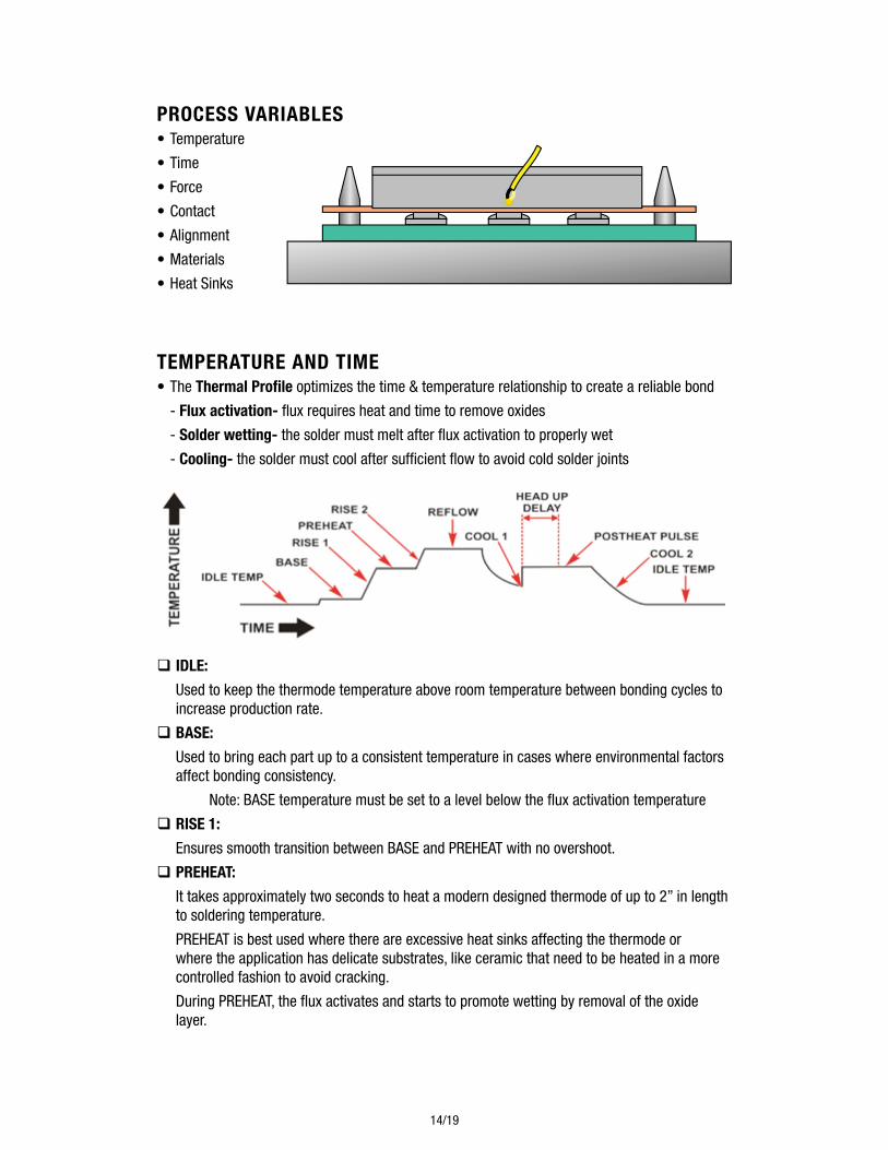
PRoCeSS vaRiableS •Temperature
•Time
•Force
•Contact
•Alignment
•Materials
•HeatSinks
TemPeRaTuRe and Time •TheThermal Profile optimizes the time & temperature relationship to create a reliable bond
- Flux activation-fluxrequiresheatandtimetoremoveoxides
- Solder wetting- the solder must melt after flux activation to properly wet
- Cooling- the solder must cool after sufficient flow to avoid cold solder joints
q idle:
Used to keep the thermode temperature above room temperature between bonding cycles to increase production rate.
q baSe:
Used to bring each part up to a consistent temperature in cases where environmental factors affect bonding consistency.
Note:BASEtemperaturemustbesettoalevelbelowthefluxactivationtemperature
q RiSe 1:
EnsuressmoothtransitionbetweenBASEandPREHEATwithnoovershoot.
q PReHeaT:
It takes approximately two seconds to heat a modern designed thermode of up to 2” in length to soldering temperature.
PREHEATisbestusedwherethereareexcessiveheatsinksaffectingthethermodeorwhere the application has delicate substrates, like ceramic that need to be heated in a more controlled fashion to avoid cracking.
DuringPREHEAT,thefluxactivatesandstartstopromotewettingbyremovaloftheoxidelayer.

15/19
q RiSe 2:
EnsuressmoothtransitionbetweenPREHEATandREFLOWwithnoovershoot.
q ReFlow:
Time and temperature should be programmed so that the solder reaches a temperature of 40°Caboveit’smeltingpointfor2-3seconds.
AlthoughSAC305solderwillreflowat218°C,theREFLOWtemperaturemustbesethigherdue to the thermal transfer losses.
Atypicalsinglesidedflexwillrequirebetween350-400°CduetothethermallossesintheKaptonmaterialandheatsinksbelow.
It is preferred to use the minimum time and temperature to achieve the desired joint, so as to minimize the parts exposure to heat and chance of damage.
q Cool 1:
IfaPOSTHEATPULSEisnotbeingused,COOL1isthetemperatureatwhichthecontrolunitwill actuate a pneumatic head to the up position.
This temperature is set to just below the solder solidification temperature. As soon as the solder becomes solid the process is ended and a joint is formed.
The cooling process can be shortened by the use of forced air cooling. The control unit can be programmed to turn on a valve that controls the flow of air at the end of the reflow period to cool the joint and thermode rapidly.
The actual temperature in the solder is typically lower than the measured thermode temperature,sotheCOOL1temperaturecanbesetto180ºCinmostcaseswithoutthechance of encountering a dry joint.
q PoSTHeaT PulSe:
APOSTHEATPULSEistypicallyonlyusedforHeatStakingapplications(notreflowsoldering).
ThePOSTHEATPULSEextendsthetimeatforcebeyondCOOL1andheatsthethermodeuptoa temperature sufficient to prohibit the thermode sticking to the heat staked parts. The Head Up Delay is used to set the time at which the control unit will actuate a pneumatic head to the up position.
q Cool 2:
IfaPOSTHEATPULSEisprogrammed,COOL2isthetemperatureatwhichthecontrolunitwillconsider the cycle complete.

16/19
FoRCe •Adequateforcemustbeappliedtoensureproperheattransfer.
•Typicalminimumpressureis12kg/cm2(170lbs/in2)acrossthermodeface.
•Measureforceusingmechanicalorelectronicforcegauge
ConTaCT•Adjustthermodetobeco-planarwithallcontactstobeheated
•Unevencontactwillcauseunevenheattransferresultingincoldsolderjoints
•Adequatesupportunderreflowareaisrequired
•Testforco-planaritywithPressureSensitivePaperorBurnTest
ConTaCT•MisalignmentofFlextoPCBcancauseshortcircuits
•MisalignmentofThermodecancauseunevenheatingandinconsistentresults
•Properpartandtoolingdesigniscriticaltosuccess
Force
Thermode notco-planar with parts
Non-contact area
Provide Support
Misaligned Thermode
Misaligned Flex Traces

17/19
maTeRialS •PartDesign,MaterialControl,andMaterialsHandlingarecritical:
P Flex Circuit
P PCB
P Flux
P Solder
maTeRialS RecommendedVolumeforSilk-screening0.127mm(.005inches)ThickSolderPaste:
SoldeR dePoSiTion meTHodS:
Primary operation Secondary operation notes
Silkscreen Solder Paste ReflowOven Can result in excess solder if volume is not controlled
Hot Dipping HotAirLeveling Air knife must be very clean
Electro-plating Mayberequiredtoincreasesolder volume
Most accurate, but minimum solder volume, expensive
Apply Solder Paste None Many particles will not melt, this method is not advised
WaveSolder Hand Touch-up(IfRequired)
Variations in solder volume can be present
1)
2)
3)
4)
Stenciled Paste - priorto reflow (IR) process
Screen mask option -40% pad coverage
Screen mask option -40% pad coverage
Solder after reflow (IR) -prior to thermodesolderingPCB
PCB

18/19
HeaT SinKS P Avoid creating heat sinks
• Aluminum,brass,orcopperfixturesconductheatawayfromthethermode
• ToolSteelistypicallyusedforfixtures
• Phenoliccanbeused,butwillwearquickly
• InsertPeekmaterialintoolingunderreflowarea
• FollowrulesforFlexandPCBdesign
• MeasuretemperatureofthermodefaceusingUltra-FlatThermocouple
PRoCeSS moniToRing q auxiliary Thermocouple:
The auxiliary thermocouple can be used to monitor the temperature of the thermode during the reflow process to ensure that heat transfer occurred:
Peek Insert
Tool Steel
Auxiliary Thermocouple
Main Thermocouple

19/19
2020(626) 303-5676 • [email protected] • www.amadaweldtech.com Copyright© 2020 AMADA WELD TECH INC.
inSPeCTion •Pressureismaintainedasthejointiscooled.Thereforethereislittlechanceofadryjoint
occurring.
•Theimprintofthethermodeshouldbeseenonthesolderjointandbeeveninwidthandlength. There should be visual evidence that reflow has occurred and when the parts are peeled apart the resulting joint will have a granular appearance over the soldered area.
•Thereshouldbenoevidenceofburningordelaminationofthepadstoboardorflex.
•Whereasinglesidedflexisused,theremaybemarkingordiscolorationonthetopofthepolyimide but no burning or separation should be seen.
•Anyfluxresiduescanbecleanedafterthereflowprocess.
•Noclean,lowresiduefluxesdonotrequirepostcleaning.
PRoCeSS moniToRing q envelope and numeric limits:
Limitscanbeprogrammedonthecontrolunittoverifytheconsistencyoftheprocess: