Fundamentals of AC machines - Festo...The workbook entitled “Basic principles of alternating...
44
Workbook With CD-ROM Festo Didactic 571791 en Fundamentals of AC machines 0.1 0.2 0.3 0.4 0.6 0.7 0.9 1.0 100 1000 900 800 700 500 400 300 200 1100 0.8 0.5 Nm 1.2 600 1200 1300 1/min 1500 20 180 160 140 100 80 60 40 120 0.2 1.8 1.6 1.4 1.0 0.8 0.6 0.4 1.2 0 220 W 2.2 A M n I P2 P2 M =f[ ] I M =f[ ] n M =f[ ] M 1 C A C B Z2 Z1 U1 U2 L1 N PE n
Transcript of Fundamentals of AC machines - Festo...The workbook entitled “Basic principles of alternating...

Workbook
With CD-ROM
Festo Didactic
571791 en
Fundamentals ofAC machines
0.1 0.2 0.3 0.4 0.6 0.7 0.9 1.0
100
1000
900
800
700
500
400
300
200
1100
0.80.5 Nm 1.2
600
1200
1300
1/min
1500
20
180
160
140
100
80
60
40
120
0.2
1.8
1.6
1.4
1.0
0.8
0.6
0.4
1.2
0
220
W
2.2
A
M
nIP2
P2 M= f [ ]
I M= f [ ]
n M= f [ ]
M1
CACB
Z2 Z1
U1
U2
L1
N
PE
n

Order no. 571791
Revision level: 06/2011
Author: Jürgen Stumpp
Editor: Frank Ebel
Graphics: Jürgen Stumpp, Thomas Ocker
Layout: 11/2011, Frank Ebel, Sophia Härer
© Festo Didactic GmbH & Co. KG, D-73770 Denkendorf, Germany, 2011
Internet: www.festo-didactic.com
e-mail: [email protected]
Reproduction, distribution and utilisation of this document, as well as the communication of its contents to
others without explicit authorisation, is prohibited. Offenders shall be held liable for payment of damages.
All rights reserved, in particular the right to file patent, utility model and registered design applications.

© Festo Didactic GmbH & Co. KG 571791 III
Contents
Intended use ____________________________________________________________________________ V
Preface ______________________________________________________________________________ VI
Introduction ____________________________________________________________________________ VIII
Work and safety instructions _______________________________________________________________ IX
Training package, “basic principles of AC machines” ____________________________________________X
Learning objectives _______________________________________________________________________ XI
Allocation of learning goals to exercises______________________________________________________ XIII
Components ____________________________________________________________________________ XV
Notes for the teacher/trainer ______________________________________________________________ XVII
Structure of the exercises ________________________________________________________________ XVIII
Component designations _________________________________________________________________ XVIII
CD ROM contents ________________________________________________________________________ XIX
Exercises and solutions
Overview of alternating current machines ______________________________________________________ 3
Exercise 1: Basic principles of the single-phase AC motor with squirrel-cage rotor (capacitor motor) _____ 5
Exercise 2: Single-phase AC motor with squirrel-cage rotor (capacitor motor) with different loads _____ 13
Exercise 3: Single-phase AC motor with squirrel-cage rotor: measurements with DriveLab software ____ 23
Overview of direct current machines, single-phase AC machines __________________________________ 37
Exercise 4: Basic principles of the universal motor ____________________________________________ 39
Exercise 5: Universal motor with different loads ______________________________________________ 45
Exercise 6: Universal motor with different loads: measurements with DriveLab software _____________ 53

IV © Festo Didactic GmbH & Co. KG 571791
Exercises and worksheets
Overview of alternating current machines ______________________________________________________ 3
Exercise 1: Basic principles of the single-phase AC motor with squirrel-cage rotor (capacitor motor) _____ 5
Exercise 2: Single-phase AC motor with squirrel-cage rotor (capacitor motor) with different loads _____ 13
Exercise 3: Single-phase AC motor with squirrel-cage rotor: measurements with DriveLab software ____ 23
Overview of direct current machines, single-phase AC machines __________________________________ 37
Exercise 4: Basic principles of the universal motor ____________________________________________ 39
Exercise 5: Universal motor with different loads ______________________________________________ 45
Exercise 6: Universal motor with different loads: measurements with DriveLab software _____________ 53

© Festo Didactic GmbH & Co. KG 571791 V
Use for intended purpose
The training package for “basic principles of alternating current machines” may only be used:
• For its intended purpose in teaching and training applications
• When its safety functions are in flawless condition
The components included in the training package are designed in accordance with the latest technology as
well as recognised safety rules. However, life and limb of the user and third parties may be endangered, and
the components may be impaired, if they are used incorrectly.
The training system from Festo Didactic has been developed and produced exclusively for training and
further education in the field of automation technology. The training companies and/or trainers must ensure
that all trainees observe the safety instructions described in this workbook.
Festo Didactic hereby excludes any and all liability for damages suffered by trainees, the training company
and/or any third parties, which occur during use of the equipment sets in situations which serve any
purpose other than training and/or vocational education, unless such damages have been caused by Festo
Didactic due to malicious intent or gross negligence.

VI © Festo Didactic GmbH & Co. KG 571791
Preface
Festo Didactic’s training system for automation and technology is geared towards various educational
backgrounds and vocational requirements. The training system is therefore broken down as follows:
• Technology-oriented training packages
• Mechatronics and factory automation
• Process automation and control technology
• Mobile robotics
• Hybrid learning factories
The training system for automation and technology is continuously updated and expanded in accordance
with developments in the field of education, as well as actual professional practice.
The technology packages deal with various technologies including pneumatics, electro-pneumatics,
hydraulics, electro-hydraulics, proportional hydraulics, programmable logic controllers, sensor technology,
electrical engineering, electronics and electric drives.
The modular design of the training system allows for applications which go above and beyond the
limitations of the individual training packages. For example, PLC actuation of pneumatic, hydraulic and
electric drives is possible.

© Festo Didactic GmbH & Co. KG 571791 VII
All training packages feature the following elements:
• Hardware
• Media
• Seminars
Hardware The hardware in the training packages is comprised of industrial components and systems that are specially
designed for training purposes. The components contained in the training packages are specifically
designed and selected for the projects in the accompanying media.
Media The media provided for the individual topics consist of a mixture of teachware and software. The teachware
includes:
• Technical literature and textbooks (standard works for teaching basic knowledge)
• Workbooks (practical exercises with supplementary instructions and sample solutions)
• Lexicons, manuals and technical books (which provide technical information on groups of topics for
further exploration)
• Transparencies and videos (for easy-to-follow, dynamic instruction)
• Posters (for presenting information in a clear-cut way)
Within the software, the following programmes are available:
• Digital training programmes (learning content specifically designed for virtual training)
• Simulation software
• Visualisation software
• Software for acquiring measurement data
• Project engineering and design engineering software
• Programming software for programmable logic controllers
The teaching and learning media are available in several languages. They are intended for use in classroom
instruction, but are also suitable for self-study.
Seminars A wide range of seminars covering the contents of the training packages round off the system for training
and vocational education.
Do you have suggestions or criticism regarding this manual?
If so, send us an e-mail at [email protected].
The authors and Festo Didactic look forward to your comments.

VIII © Festo Didactic GmbH & Co. KG 571791
Introduction
This workbook is part of the learning system for automation and technology from Festo Didactic GmbH & Co.
KG. The system provides a solid basis for practice-oriented basic and further training. Training package
TP 1410, “Servo brake and drive system”, deals with the following topics:
• Basic principles of DC machines
• Basic principles of AC machines
• Basic principles of 3-phase machines
The workbook entitled “Basic principles of alternating current machines” provides an introduction to the
topic of electric machines with AC connection. We come into contact with AC drives every day, as these
motors are commonly used in household appliances, and above all in handheld electrical tools. Knowledge
regarding layout, connection and applications ranges is imparted. In doing so, the machines are exposed to
a wide range of simulated load situations in order to ascertain their capabilities.
Technical prerequisites for setting up the circuits include:
• A laboratory workbench equipped with an A4 frame
• Servo brake and drive system equipment set TP 1410
• 230 V AC mains outlet
• Universal motor
• Capacitor motor
• Components for controlling the electric machines
• Laboratory safety cables
The circuits for all 6 exercises are set up using the TP 1410 equipment set and the AC drives.
Data sheets for the individual components are also available (universal motor, capacitor motor etc.).

© Festo Didactic GmbH & Co. KG 571791 IX
Work and safety instructions
General information • Trainees should only work with the circuits under the supervision of a trainer.
• Observe specifications included in the technical data for the individual components, and in particular all
safety instructions!
• Malfunctions which may impair safety must not be generated in the training environment and must be
eliminated immediately.
Mechanical components • Attach all components intended for mounting of this sort to the A4 frame.
• Adhere to the instructions regarding positioning of the components.
Electrical components
• The servo brake and drive system (motor test bench) may only be placed into service with an additional
protective earth conductor.
PE
L1DC+
L2 L3/NDC-
Input
Output
PE
• Always connect the motor’s thermo-switch to the “Motor ϑ” input at the motor test bench.
• Establish or interrupt electrical connections only in the absence of voltage!
• Use only connecting cables with safety plugs for electrical connections.
• Always pull the safety plug when disconnecting connecting cables – never pull the cable.

X © Festo Didactic GmbH & Co. KG 571791
Training package, “basic principles of AC machines”
The subject matter of this section of the TP 1410 training package is basic principles of AC machines.
Individual components from training package TP 1410 may also be included in other packages.
Important TP 1410 components • Permanently installed workstation with A4 frame
• Equipment set or individual components (universal motor, capacitor motor)
• Laboratory safety cables
• Set of laboratory equipment
Media The teachware for training package TP 1410 consists of three workbooks. The workbooks contain
worksheets for each exercise, the solutions for each individual worksheet and a CD-ROM. A set of ready-to-
use exercises and worksheets is included for each exercise.
Data sheets for the hardware components are made available along with the training package.
Media
Workbook Basic principles of DC machines
Basic principles of AC machines
Basic principles of 3-phase machines
Digital training programmes WBT, “Electric drives 1”
WBT, “Electric drives 2”
Overview of media for training package TP 1410
Software available for training package TP 1410 includes digital learning programmes entitled “Electric
drives 1” and “Electric drives 2”. These programmes explore the basic principles of electric drive technology
in detail. Training content is elucidated on the basis of practical case studies in a systematic, applications-
oriented fashion.
Further training materials can be found in our catalogue and on the Internet. The learning system for
automation and technology is continuously updated and expanded. Transparency sets, videos, CD-ROMs,
DVDs and training programmes as well as additional teachware are offered in several languages.

© Festo Didactic GmbH & Co. KG 571791 XI
Learning objectives
Basic principles of AC machines – single-phase AC motor with squirrel-cage rotor (capacitor motor) with different loads
• You become familiar with the basic function of the capacitor motor.
• You become familiar with the connection plate on the motor with all of its designations
• You become familiar with the motor’s circuitry including main and auxiliary windings, as well as the
starter and operating capacitors.
• You become familiar with terminal board wiring for clockwise and anti-clockwise motor operation.
• You become familiar with the measuring circuit for checking the specifications in the rating plate.
• You become familiar with checking the specifications in the rating plate by performing measurements
while the motor is idling, and while running at nominal load.
• You learn how to work with the motor test bench and DriveLab software.
• You become familiar with the measuring circuit for recording the individual points in the characteristic
load curves.
• You become familiar with starting the motor up with various loads.
• You learn to calculate the missing values in the table.
• You learn how to create a chart with the motor’s characteristic load curves.
• You learn how to evaluate characteristic load curves.
• You learn how to calculate reactive power, efficiency and power factor.
• You learn how to create a graph with the calculated values.
• You learn how to evaluate the graph.
Basic principles of AC machines – universal motor • You become familiar with the term “universal motor”.
• You become familiar with the ohmic resistances of the armature winding and the excitation winding in
the universal motor.
• You learn to evaluate the resistance values of armature and excitation windings.
• You become familiar with the problem associated with the universal motor when idling.
• You become familiar with the layout of the rotor of the universal motor.
• You learn how to reverse the direction of rotation of the universal motor.
• You learn how to change the speed of the universal motor.
• You become familiar with possible applications for universal motors.
• You learn how to work with the motor test bench and DriveLab software.
• You will be aware of the significance of the data included on the motor’s rating plate.
• You become familiar with the measuring circuit for recording the individual points in the characteristic
load curves.
• You become familiar with starting the motor up with various loads.
• You learn to calculate the missing values in the load table.
• You learn how to create a chart with the motor’s characteristic load curves.
• You learn how to evaluate characteristic load curves.

XII © Festo Didactic GmbH & Co. KG 571791
Use of the servo brake and drive system and DriveLab software • You learn how to work with the servo brake and drive system, and DriveLab software.
• You learn how to connect and commission the motors with the servo brake and drive system and
DriveLab software.
• You become familiar with the programming interface for DriveLab software.
• You learn how to select and change measured variables at the X-axis and the Y-axis.
• You learn how to customise the colour and style of measured curves.
• You learn to adjust speed and torque from the computer.
• You learn to prepare and start a measurement from the computer.
• You learn to record and document characteristic load curves at the computer.

© Festo Didactic GmbH & Co. KG 571791 XIII
Allocation of learning objectives to exercises
Exercise 1 2 3 4 5 6
Learning objective
You become familiar with the basic function of the capacitor motor. •
You become familiar with the connection plate on the motor with all of its designations •
You become familiar with the motor’s circuitry including main and auxiliary windings, as well as
the starter and operating capacitors. •
You become familiar with terminal board wiring for clockwise and anti-clockwise motor
operation. •
You become familiar with the measuring circuit for checking the specifications in the rating
plate. •
You become familiar with checking the specifications in the rating plate by performing
measurements while the motor is idling, and while running at nominal load. •
You learn how to work with the motor test bench and DriveLab software. •
You become familiar with the measuring circuit for recording the individual points in the
characteristic load curves. •
You become familiar with starting the motor up with various loads. •
You learn to calculate the missing values in the table. •
You learn how to create a chart with the motor’s characteristic load curves. •
You learn how to evaluate characteristic load curves. •
You learn how to calculate reactive power, efficiency and power factor. •
You learn how to create a graph with the calculated values. •
You learn how to evaluate the graph. •
You learn how to work with the motor test bench and DriveLab software. • •
You learn how to connect and commission the capacitor motor with the motor test bench and
DriveLab software. •
You learn to connect and commission the universal motor with the motor test bench and
DriveLab software. •
You become familiar with the programming interface for DriveLab software. • •
You learn how to select and change measured variables at the X-axis and the Y-axis. • •
You learn how to customise the colour and style of measured curves. • •
You learn to adjust speed and torque from the computer. • •
You learn to prepare and start a measurement from the computer. • •
You learn to enter a new motor to the motor library. • •
You learn to record and document characteristic load curves at the computer. • •

XIV © Festo Didactic GmbH & Co. KG 571791
Exercise 1 2 3 4 5 6
Learning objective
You become familiar with the term “universal motor”. •
You become familiar with the ohmic resistances of the armature winding and the excitation
winding in the universal motor. •
You learn to evaluate the resistance values of armature and excitation windings. •
You become familiar with the problem associated with the universal motor when idling. •
You become familiar with the layout of the rotor of the universal motor. •
You learn how to reverse the direction of rotation of the universal motor. •
You learn how to change the speed of the universal motor. •
You become familiar with possible applications for universal motors. •
You learn how to work with the motor test bench and DriveLab software. •
You will be aware of the significance of the data included on the motor’s rating plate. •
You become familiar with the measuring circuit for recording the individual points in the
characteristic load curves. •
You become familiar with starting the motor up with various loads. •
You learn to calculate the missing values in the load table. •
You learn how to create a chart with the motor’s characteristic load curves. •
You learn how to evaluate characteristic load curves. •

© Festo Didactic GmbH & Co. KG 571791 XV
Components
The components included in the training package for “basic principles of AC machines” impart knowledge
regarding setup, connection and the range of applications of AC machines. In order to set up functional
circuits, you will also need a laboratory workstation (optionally equipped with an A4 frame), “servo brake
and drive system” equipment set TP 1410, a 230 V AC power supply and controllers for the electric
machines.
“Servo brake and drive system” equipment set TP 1410
Component Order no. Quantity
Servo brake and drive system 571870 1
Electric machines, “basic principles of AC machines”
Component Order no. Quantity
Single-phase AC motor with squirrel-cage rotor (capacitor motor) 571871 1
Universal motor 571872 1
Controllers for the electric machines
Component Order no. Quantity
EduTrainer 3-phase power supply 571812 1
EduTrainer 24 V power supply 571813 1
EduTrainer contactor board 571814 1
Motor technology contactor set 571816 1
EduTrainer operator and signaling unit 571815 1

XVI © Festo Didactic GmbH & Co. KG 571791
Graphic symbols, equipment set
Component Graphic symbol
Single-phase AC motor with squirrel-cage rotor
(capacitor motor)
M1
Universal motor
M

© Festo Didactic GmbH & Co. KG 571791 XVII
Notes for the teacher/trainer
Learning objectives The overall learning objective of this workbook is familiarisation with the basic principles of AC machines.
Direct interplay of theory and practice ensures fast progress and long-lasting learning. The more specific
learning objectives are documented in the matrix. Concrete, individual learning objectives are assigned to
each exercise.
Required time The time required for working through the exercises depends on the learner’s previous knowledge of the
subject matter. For apprentices in the field of electrical engineering: approx. 3 days With training as a skilled
worker: approx. 1 day
Components The workbook and the components are designed to be used together. A single-phase AC motor with
squirrel-cage rotor (capacitor motor) is required for exercises 1 through 3. A universal motor is required for
exercises 4 through 6.
Standards The following standards apply to this workbook:
EN 60617-2 through
EN 60617-8: Graphic symbols for circuit diagrams
EN 81346-2: Industrial systems, installations and equipment and industrial products;
structuring principles and reference designations
Identification of solutions Solutions and supplements in graphics or diagrams appear in red.
Identification in the worksheets Texts which require completion are identified with a grid or grey table cells.
Graphics and diagrams which require completion include a grid.
Notes for the lesson Additional information regarding the individual components and the circuits is provided here. These notes
are not included in the worksheets.
Learning topics Allocation of the fields of learning offered by vocational schools to the training subject matter of “basic
principles of AC machines” is provided below for selected vocations.

XVIII © Festo Didactic GmbH & Co. KG 571791
Vocation Topic
Electronics engineer for
automation technology
Analysing electrical systems and testing their functions
Analysing and adapting control systems
Analysing systems and testing their safety
Mechatronics technician Installation of electric equipment, taking technical safety aspects into account
Examination of the flow of energy and information in electrical, pneumatic and hydraulic assemblies
Implementation of mechatronic subsystems
Commissioning, troubleshooting and repair
Structure of the exercises
All 6 exercises have the same structure and are broken down into:
• Title
• Learning objectives
• Problem description
• Positional sketch
• Project assignments
• Work aids
• Worksheets
The workbook includes the solutions for all of the worksheets.
Component designations
The components in the circuit diagrams are identified in accordance with EN 81346-2. Letters are assigned
as appropriate to each component. Multiple components of the same type within a single circuit are
numbered.
Relays: K, K1, K2, …
Switches/pushbuttons: S, S1, S2, …
Contactors: Q, Q1, Q2, …
Fuses: F, F1, F2, ...
Indicators: P, P1, P2, ...

© Festo Didactic GmbH & Co. KG 571791 XIX
Contents of the CD-ROM
The workbook is included on the accompanying CD-ROM as a PDF file. The CD-ROM also provides you with
additional media.
The CD-ROM contains the following folders:
• Operating instructions
• Illustrations
• Data sheets
Operating instructions Operating instructions are provided for various components included in the training package. These
instructions are helpful when using and commissioning the components.
Illustrations Photos and graphics of components and industrial applications are made available. These can be used to
illustrate individual tasks or to supplement project presentations.
Data sheets The technical data for the components included in the training package are available as PDF files.

XX © Festo Didactic GmbH & Co. KG 571791

© Festo Didactic GmbH & Co. KG 571791 1
Contents
Exercises and solutions
Overview of alternating current machines ______________________________________________________ 3
Exercise 1: Basic principles of the single-phase AC motor with squirrel-cage rotor (capacitor motor) _____ 5
Exercise 2: Single-phase AC motor with squirrel-cage rotor (capacitor motor) with different loads _____ 13
Exercise 3: Single-phase AC motor with squirrel-cage rotor: measurements with DriveLab software ____ 23
Overview of direct current machines, single-phase AC machines __________________________________ 37
Exercise 4: Basic principles of the universal motor ____________________________________________ 39
Exercise 5: Universal motor with different loads ______________________________________________ 45
Exercise 6: Universal motor with different loads: measurements with DriveLab software _____________ 53

2 © Festo Didactic GmbH & Co. KG 571791

© Festo Didactic GmbH & Co. KG 571791 3
Overview of alternating current machines
AC machines
Transformers Rotating machines
Specialtransformerse.g.leak and autotransformers
Three-phasetransformer
Single-phasetransformer
Asynchronousmachines
Synchronousmachines
Motors Generators Single-phasemachines
Three-phasemachines
Motors withauxiliarywindingorcapacitor
Motors withsquirrel-cagerotor
Specialmachinese.g.pole switchingand repulsionmotors
Motors withslip-ringrotor
Specialmachinese.g.linear andcollectormotors

4 © Festo Didactic GmbH & Co. KG 571791

© Festo Didactic GmbH & Co. KG 571791 5
Exercise 1 Basic principles of the single-phase AC motor with squirrel-cage rotor
(capacitor motor)
Learning objectives After completing this exercise:
• You will be familiar with the basic function of the capacitor motor.
• You will be familiar with the connection plate on the motor with all of its designations
• You will be familiar with the motor’s circuitry including main and auxiliary windings, as well as the
starter and operating capacitors.
• You will be familiar with terminal board wiring for clockwise and anti-clockwise motor operation.
• You will be familiar with the measuring circuit for checking the specifications in the rating plate.
• You will be familiar with checking the specifications in the rating plate by performing measurements
while the motor is idling, and while running at nominal load.
Problem description 230 V single-phase alternating voltage (L1 and N) is the only option available for operating an air
compressor.
Due to the fact that high-inertia starting conditions can be expected with the compressor, a capacitor motor
with starter and operating capacitors will be used as a drive. The motor needs to be tested for suitability in
the training workshop. The examination results will need to be documented in a report.
Air compressor

Exercise 1 – Basic principles of the single-phase AC motor with squirrel-cage rotor (capacitor motor)
6 © Festo Didactic GmbH & Co. KG 571791
Project assignments 1. Describe the basic function of a single-phase AC motor with squirrel-cage rotor (capacitor motor).
2. Complete the specifications for the motor’s connection plate.
3. Complete the motor circuit with main and auxiliary windings, as well as the starter and operating
capacitors.
4. Complete the specifications for clockwise and anti-clockwise motor operation.
5. Complete the measuring circuit for checking the specifications in the rating plate.
6. Check the specifications on the motor’s rating plate for no-load operation and operation at nominal load
by means of measurement and calculation.
Work aids • Textbooks, books of tables
• Excerpts from manufacturers’ catalogues
• Data sheets
• Servo brake and drive system manual
• Internet
• WBT, “Electric drives 1”

Exercise 1 – Basic principles of the single-phase AC motor with squirrel-cage rotor (capacitor motor)
© Festo Didactic GmbH & Co. KG 571791 7
1. Basic function of the capacitor motor
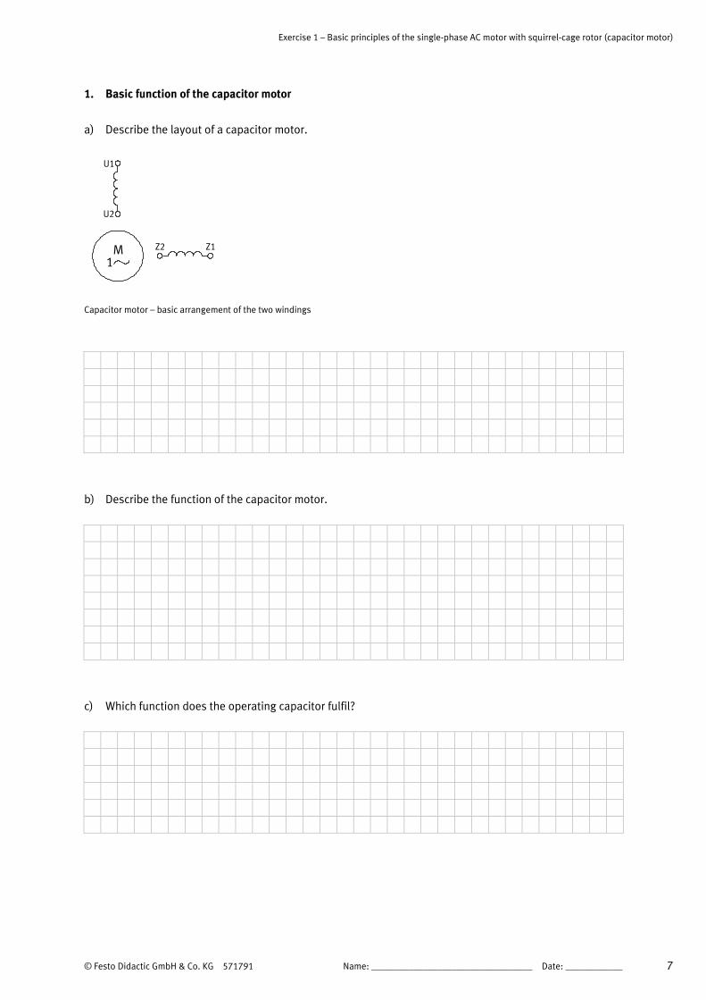
a) Describe the layout of a capacitor motor.
Z2 Z1
U1
U2
M1
Capacitor motor – basic arrangement of the two windings
Two windings are arranged at a 90° angle to each other within the stator’s laminated core. This is the
main winding with the designations U1 and U2. It occupies two thirds of the stator slots.
The auxiliary winding with the designations Z1 and Z2 is accommodated in the remaining slots.
Depending on starting conditions, the single-phase motor is also equipped with starter and operating
capacitors.
b) Describe the function of the capacitor motor.
In order to achieve phase displacement between the two windings, resulting in a rotating field, a
capacitor must be connected in series to the auxiliary winding.
In the case of a single-phase motor with an operating capacitor, the auxiliary winding is continuously
energised along with the series connected main winding.
In the event of high-inertia starting conditions, a starter capacitor is connected in parallel to the
operating capacitor. The starter capacitor is switched off by a centrifugal switch after the motor has
been started up.
c) Which function does the operating capacitor fulfil?
Operating capacitor CB assures a smooth running motor and a better power factor. The capacitance of
the operating capacitor should be dimensioned such that the auxiliary winding does not become
impermissibly hot. The capacitance of the operating capacitor accommodates close to 1 kvar of
reactive power per kilowatt of motor power.
Exercise 1 – Basic principles of the single-phase AC motor with squirrel-cage rotor (capacitor motor)
8 © Festo Didactic GmbH & Co. KG 571791
d) Which function does the starter capacitor fulfil?
In order to increase the motor’s starting torque, the capacitor’s capacitance value must also be
increased. The increase in capacitance is achieved by connecting starter capacitor CA in parallel. The
starter capacitor is switched off by a centrifugal switch after the motor has been started up, assuring
that the auxiliary winding does not become impermissibly hot.
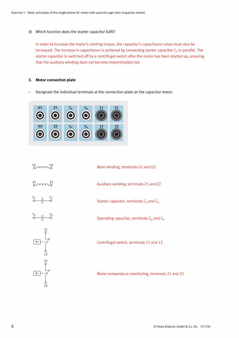
2. Motor connection plate – Designate the individual terminals at the connection plate on the capacitor motor.
U2U1
Main winding, terminals U1 and U2
Z2Z1
Auxiliary winding, terminals Z1 and Z2
Starter capacitor, terminals CA and CA
CB CB
Operating capacitor, terminals CB and CB
Centrifugal switch, terminals 11 and 12
Motor temperature monitoring, terminals 21 and 22
Exercise 1 – Basic principles of the single-phase AC motor with squirrel-cage rotor (capacitor motor)
© Festo Didactic GmbH & Co. KG 571791 9
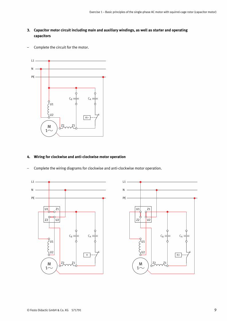
3. Capacitor motor circuit including main and auxiliary windings, as well as starter and operating capacitors
– Complete the circuit for the motor.
CACB
Z2 Z1
U1
U2
L1
N
PE
n
M1
4. Wiring for clockwise and anti-clockwise motor operation
– Complete the wiring diagrams for clockwise and anti-clockwise motor operation.
CACB
Z2 Z1
U1
U2
L1
N
PE
n
Z2
Z1U1
U2
M1
CACB
Z2 Z1
U1
U2
L1
N
PE
Z2
Z1U1
U2
n
M1
Exercise 1 – Basic principles of the single-phase AC motor with squirrel-cage rotor (capacitor motor)
10 © Festo Didactic GmbH & Co. KG 571791
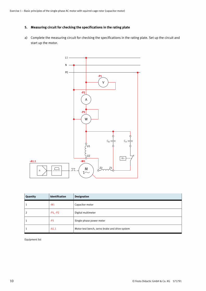
5. Measuring circuit for checking the specifications in the rating plate
a) Complete the measuring circuit for checking the specifications in the rating plate. Set up the circuit and
start up the motor.
CACB
Z2 Z1
U1
U2n
-M1
n
-A1.1
L1
N
PE
V
A
-P1
-P2
W
-P3
M1
Quantity Identification Designation
1 -M1 Capacitor motor
2 -P1, -P2 Digital multimeter
1 -P3 Single-phase power meter
1 -A1.1 Motor test bench, servo brake and drive system
Equipment list

Exercise 1 – Basic principles of the single-phase AC motor with squirrel-cage rotor (capacitor motor)
© Festo Didactic GmbH & Co. KG 571791 11
b) Set up the circuit.
– Use the 230 V capacitor motor (order no. 571872).
6. Checking the specifications in the rating plate by means of measurement and calculation
a) The motor is connected to the motor test bench in order to perform measurement. The motor test bench
is switched on but it is not connected to the PC. The motor is switched on.
b) Measurement is performed first of all during no-load operation. Enter the measured values to the “No-
load” column in the table.
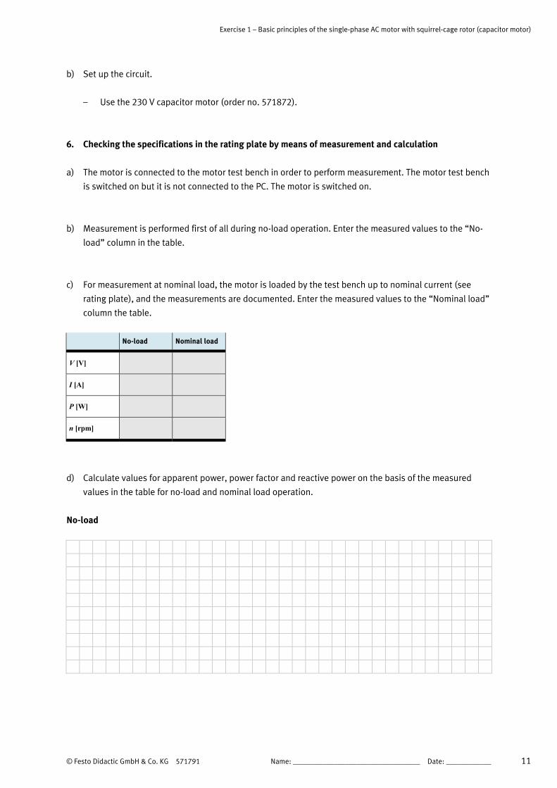
c) For measurement at nominal load, the motor is loaded by the test bench up to nominal current (see
rating plate), and the measurements are documented. Enter the measured values to the “Nominal load”
column the table.
No-load Nominal load
V [V] 228 228
I [A] 1.2 1.86
P [W] 216 352
n [rpm] 1480 1400
d) Calculate values for apparent power, power factor and reactive power on the basis of the measured
values in the table for no-load and nominal load operation.
No-load
Apparent power S: 228 V 1,2 A = 274 VAS U I= ⋅ = ⋅
Power factor cos φ: 216 W
= 0,78274 VA
PcosS
ϕ = =
Reactive power Q: 274 VA 0,63 = 173 varQ S sin= ⋅ ϕ = ⋅

Exercise 1 – Basic principles of the single-phase AC motor with squirrel-cage rotor (capacitor motor)
12 © Festo Didactic GmbH & Co. KG 571791
Nominal load
Apparent power S: 228 V 1,86 A = 424 VAS U I= ⋅ = ⋅
Power factor cos φ: 352 W= 0,83
424 VAPcosS
ϕ = =
Reactive power Q: 424 VA 0,56 = 237 varQ S sin= ⋅ ϕ = ⋅
Monitoring capacitance of CA
Measured values: U = 230 V
I = 1.75 A
Reactance XC: 230 V
= 131,42 Ω1,75 A
CC
C
UX
I= =
Capacitance C: -1
1 1= 24,2 μF
2 2 50 s 131,42 ΩCC
f X= =
⋅ π ⋅ ⋅ ⋅ π ⋅ ⋅
Monitoring capacitance of CB
Measured values: U = 220 V
I = 0.7 A
Reactance XC: 220 V
= 314,28 Ω0,7 A
CC
C
UX
I= =
Capacitance C: -1
1 1= 10,13 μF
2 2 50 s 314,28 ΩCC
f X= =
⋅ π ⋅ ⋅ ⋅ π ⋅ ⋅

© Festo Didactic GmbH & Co. KG 571791 1
Contents
Exercises and worksheets
Overview of alternating current machines ______________________________________________________ 3
Exercise 1: Basic principles of the single-phase AC motor with squirrel-cage rotor (capacitor motor) _____ 5
Exercise 2: Single-phase AC motor with squirrel-cage rotor (capacitor motor) with different loads _____ 13
Exercise 3: Single-phase AC motor with squirrel-cage rotor: measurements with DriveLab software ____ 23
Overview of direct current machines, single-phase AC machines __________________________________ 37
Exercise 4: Basic principles of the universal motor ____________________________________________ 39
Exercise 5: Universal motor with different loads ______________________________________________ 45
Exercise 6: Universal motor with different loads: measurements with DriveLab software _____________ 53

2 © Festo Didactic GmbH & Co. KG 571791

© Festo Didactic GmbH & Co. KG 571791 3
Overview of alternating current machines
AC machines
Transformers Rotating machines
Specialtransformerse.g.leak and autotransformers
Three-phasetransformer
Single-phasetransformer
Asynchronousmachines
Synchronousmachines
Motors Generators Single-phasemachines
Three-phasemachines
Motors withauxiliarywindingorcapacitor
Motors withsquirrel-cagerotor
Specialmachinese.g.pole switchingand repulsionmotors
Motors withslip-ringrotor
Specialmachinese.g.linear andcollectormotors

4 © Festo Didactic GmbH & Co. KG 571791

© Festo Didactic GmbH & Co. KG 571791 5
Exercise 1 Basic principles of the single-phase AC motor with squirrel-cage rotor
(capacitor motor)
Learning objectives After completing this exercise:
• You will be familiar with the basic function of the capacitor motor.
• You will be familiar with the connection plate on the motor with all of its designations
• You will be familiar with the motor’s circuitry including main and auxiliary windings, as well as the
starter and operating capacitors.
• You will be familiar with terminal board wiring for clockwise and anti-clockwise motor operation.
• You will be familiar with the measuring circuit for checking the specifications in the rating plate.
• You will be familiar with checking the specifications in the rating plate by performing measurements
while the motor is idling, and while running at nominal load.
Problem description 230 V single-phase alternating voltage (L1 and N) is the only option available for operating an air
compressor.
Due to the fact that high-inertia starting conditions can be expected with the compressor, a capacitor motor
with starter and operating capacitors will be used as a drive. The motor needs to be tested for suitability in
the training workshop. The examination results will need to be documented in a report.
Air compressor

Exercise 1 – Basic principles of the single-phase AC motor with squirrel-cage rotor (capacitor motor)
6 Name: __________________________________ Date: ____________ © Festo Didactic GmbH & Co. KG 571791
Project assignments 1. Describe the basic function of a single-phase AC motor with squirrel-cage rotor (capacitor motor).
2. Complete the specifications for the motor’s connection plate.
3. Complete the motor circuit with main and auxiliary windings, as well as the starter and operating
capacitors.
4. Complete the specifications for clockwise and anti-clockwise motor operation.
5. Complete the measuring circuit for checking the specifications in the rating plate.
6. Check the specifications on the motor’s rating plate for no-load operation and operation at nominal load
by means of measurement and calculation.
Work aids • Textbooks, books of tables
• Excerpts from manufacturers’ catalogues
• Data sheets
• Servo brake and drive system manual
• Internet
• WBT, “Electric drives 1”
Exercise 1 – Basic principles of the single-phase AC motor with squirrel-cage rotor (capacitor motor)
© Festo Didactic GmbH & Co. KG 571791 Name: __________________________________ Date: ____________ 7
1. Basic function of the capacitor motor
a) Describe the layout of a capacitor motor.
Z2 Z1
U1
U2
M1
Capacitor motor – basic arrangement of the two windings
b) Describe the function of the capacitor motor.
c) Which function does the operating capacitor fulfil?

Exercise 1 – Basic principles of the single-phase AC motor with squirrel-cage rotor (capacitor motor)
8 Name: __________________________________ Date: ____________ © Festo Didactic GmbH & Co. KG 571791
d) Which function does the starter capacitor fulfil?
2. Motor connection plate – Designate the individual terminals at the connection plate on the capacitor motor.
U2U1
Z2Z1
CB CB

Exercise 1 – Basic principles of the single-phase AC motor with squirrel-cage rotor (capacitor motor)
© Festo Didactic GmbH & Co. KG 571791 Name: __________________________________ Date: ____________ 9
3. Capacitor motor circuit including main and auxiliary windings, as well as starter and operating capacitors
– Complete the circuit for the motor.
CACB
Z2 Z1
U1
U2
L1
N
PE
n>
M1
4. Wiring for clockwise and anti-clockwise motor operation
– Complete the wiring diagrams for clockwise and anti-clockwise motor operation.
CACB
Z2 Z1
U1
U2
L1
N
PE
n
Z2
Z1U1
U2
M1
CACB
Z2 Z1
U1
U2
L1
N
PE
n
Z2
Z1U1
U2
M1

Exercise 1 – Basic principles of the single-phase AC motor with squirrel-cage rotor (capacitor motor)
10 Name: __________________________________ Date: ____________ © Festo Didactic GmbH & Co. KG 571791
5. Measuring circuit for checking the specifications in the rating plate
a) Complete the measuring circuit for checking the specifications in the rating plate. Set up the circuit and
start up the motor.
CACB
Z2 Z1
U1
U2n>
n
L1
N
PE
V
A
W
M1
Quantity Identification Designation
1 Capacitor motor
2 Digital multimeter
1 Single-phase power meter
1 Motor test bench, servo brake and drive system
Equipment list
Exercise 1 – Basic principles of the single-phase AC motor with squirrel-cage rotor (capacitor motor)
© Festo Didactic GmbH & Co. KG 571791 Name: __________________________________ Date: ____________ 11
b) Set up the circuit.
– Use the 230 V capacitor motor (order no. 571872).
6. Checking the specifications in the rating plate by means of measurement and calculation
a) The motor is connected to the motor test bench in order to perform measurement. The motor test bench
is switched on but it is not connected to the PC. The motor is switched on.
b) Measurement is performed first of all during no-load operation. Enter the measured values to the “No-
load” column in the table.
c) For measurement at nominal load, the motor is loaded by the test bench up to nominal current (see
rating plate), and the measurements are documented. Enter the measured values to the “Nominal load”
column the table.
No-load Nominal load
V [V]
I [A]
P [W]
n [rpm]
d) Calculate values for apparent power, power factor and reactive power on the basis of the measured
values in the table for no-load and nominal load operation.
No-load

Exercise 1 – Basic principles of the single-phase AC motor with squirrel-cage rotor (capacitor motor)
12 Name: __________________________________ Date: ____________ © Festo Didactic GmbH & Co. KG 571791
Nominal load
Monitoring capacitance of CA
Monitoring capacitance of CB