
FUNDAMENTAL STUDIES OF ELECTRO-SEPARATION · In the following paragraphs we attempt to highlight...
23
FINAL TECHNICAL REPORT October 1, 2007, through September 30, 2008 Project Title: FUNDAMENTAL STUDIES OF ELECTRO-SEPARATION ICCI Project Number: 07-1/ER16 Principal Investigator: Dr. Asghar Esmaeeli, SIUC Project Manager: Mr. Joseph C. Hirschi, ICCI ABSTRACT This research explored the effect of electric fields on the dynamics of solid and mobile particles. Specifically, the goal was to identify how an electric field can be used to manipulate particles to clean coal-derived liquids. The project was carried out by resorting to computer simulations where governing electrohydrodynamic equations of particles and fluid flow were solved by a multiphase-flow code developed in house. Initially, particles were distributed randomly inside a channel in quiescent fluid and were exposed to a uniform DC electric field in the vertical direction. As a result of dielectric mismatch between particles and the fluid, electric stresses developed at the surface of the particles which led to their motion, deformation, and fluid flow. Transient behaviors of particles were studied as a function of governing parameters of the problem, such as material properties of particles. Results suggest that ratios of electrical conductivity and permittivity of particles to corresponding quantities in the ambient fluid are critical factors in determining particle behavior. Depending on the relative magnitude of these two parameters, two particles may attract or repel each other, and they may elongate in the direction parallel or perpendicular to the electric field. It was found that as density and viscosity of particles increase, the rate of attraction of particles towards electrodes and their interactions with peers will decrease. It was shown that as the volume fraction of suspension increases, the rate of particle interaction increases and interactions of unequal-sized particles will be dominated by larger particles.
Transcript of FUNDAMENTAL STUDIES OF ELECTRO-SEPARATION · In the following paragraphs we attempt to highlight...

FINAL TECHNICAL REPORT October 1, 2007, through September 30, 2008
Project Title: FUNDAMENTAL STUDIES OF ELECTRO-SEPARATION ICCI Project Number: 07-1/ER16 Principal Investigator: Dr. Asghar Esmaeeli, SIUC Project Manager: Mr. Joseph C. Hirschi, ICCI
ABSTRACT
This research explored the effect of electric fields on the dynamics of solid and mobile particles. Specifically, the goal was to identify how an electric field can be used to manipulate particles to clean coal-derived liquids. The project was carried out by resorting to computer simulations where governing electrohydrodynamic equations of particles and fluid flow were solved by a multiphase-flow code developed in house. Initially, particles were distributed randomly inside a channel in quiescent fluid and were exposed to a uniform DC electric field in the vertical direction. As a result of dielectric mismatch between particles and the fluid, electric stresses developed at the surface of the particles which led to their motion, deformation, and fluid flow. Transient behaviors of particles were studied as a function of governing parameters of the problem, such as material properties of particles. Results suggest that ratios of electrical conductivity and permittivity of particles to corresponding quantities in the ambient fluid are critical factors in determining particle behavior. Depending on the relative magnitude of these two parameters, two particles may attract or repel each other, and they may elongate in the direction parallel or perpendicular to the electric field. It was found that as density and viscosity of particles increase, the rate of attraction of particles towards electrodes and their interactions with peers will decrease. It was shown that as the volume fraction of suspension increases, the rate of particle interaction increases and interactions of unequal-sized particles will be dominated by larger particles.
EXECUTIVE SUMMARY
This study explored parameters that affect the electro-separation of particles using direct numerical simulation. Important nondimensional parameters of the problem were identified using individual parameters. Then, a series of computer simulations were performed where, in each run, the effect of one of the nondimensional parameters was explored while keeping all other nondimensional parameters constant. A front tracking/finite difference technique was used and governing equations of fluid flow and electric field were solved for the particles and the fluid. The domain was a rectangular channel, open at the left and the right (i.e., periodic) and bounded by walls at the top and the bottom. The electric field was established by imposing an electric potential difference at the walls (electrodes). Particles were distributed randomly in the domain and the fluid was quiescent for most of the simulations. The effect of electro-physical properties of the particles and the ambient fluid, the particle volume fraction, the imposed flow rate, the particle size distribution, and the particles’ initial proximity to the walls were studied. It was shown that the two most important parameters influencing particle aggregation and separation, as well as their deformation and fluid flow motion, were the relative magnitude of the ratio of electrical conductivity and permittivity of particles to corresponding quantities for the ambient fluid. Depending on these ratios, a particle suspended in an electric field may elongate in the direction parallel or perpendicular to the electric field and may be pushed off by the electrodes or attracted towards them. This suggests that particles whose deformation is perpendicular to the direction of the electric field will attract, whereas particles whose deformation is in the direction of the electric field show a richer physics in the sense that they may be attracted towards each other or repelled by one another. The effect of density and viscosity of particles on their dynamics was studied and it was shown that as these parameters are increased, the rate of interactions between particles decreases. For the range of parameters studied here, it was shown that the flow rate tends to force particles to stay together. The effect of particle volume fraction and size distribution was also studied and it was found that particle aggregation rate increases as the volume fraction is increased. Also, larger particles play a more dominant role in interactions of unequal-sized particles.

1
OBJECTIVES Objectives of the current research are as follows: • To investigate the mechanisms of electro-separation by simulating the evolution of
emulsions of micron-sized drops or solid particles in an electric field.
• To explore the effect of various controlling parameters such as fluid velocity, strength of the electric field, buoyancy, void fraction, dielectric properties of fluids/particles, and particle size distribution on separation efficiency.
TASKS
Task 1: Effect of Strength of Electric Field Here the goal was to evaluate the effect of strength of the electric field on particle separation. This was achieved by keeping other variables constant while changing the electric potential difference incrementally. Task 2: Effect of Flow Rate Here the goal was to understand the effect of flow rate on phase separation. This was achieved by imposing a constant pressure gradient on the fluid in the horizontal direction. Task 3: Effect of Void Fraction Here the goal was to explore the effect of particle concentration on the rate of aggregation of particles. This was achieved by keeping the size of the computational domain the same, while increasing the initial radius of the particles. Task 4: Effect of Size Distribution Here the goal was to explore interactions of unequal-sized particles. This was achieved by performing simulations where the size of the computational domain was kept fixed while the suspension consisted of particles of small and large radii. Task 5: Effect of Material Properties This task was performed by investigating the effect of electro-physical properties of particles and the ambient fluid on the dynamics. This was achieved by looking at particles of different electrical conductivity and permittivity ratios as well as particles of different density and viscosity.
INTRODUCTION AND BACKGROUND Commercial processing of coal relies strongly on separation techniques. Unit operations that separate chemicals and particles from coal consume large amounts of energy and also produce considerable amounts of emissions. As such, separation economics and its environmental impact play a vital role in the quality and marketability of processed coal. Most separation techniques operate based on a single chemical or physical driving force where the common practice is to conduct the slurry or coal-derived liquids through a
2
series of units to separate various components. This approach has two main drawbacks as the overall separation efficiency is limited by the efficiency in each step and also the fact that using a single driving force at each step may result in loss of the desired product via a waste stream. To alleviate these problems, attempts have been made to integrate two or more separation driving forces in one step. In particular, interest has shifted toward electro-separation where an electric field is combined with other driving forces to enhance efficiency. The electric field offers great potential as electricity is readily available, does not need to be stored, is not toxic, and does not have disposal problems. Electro-separation, therefore, is posed to play a vital role in increasing the efficiency of conventional separation techniques and improving their environmental impact. The idea of electro-separation is not entirely new. Indeed, one can refer to separation techniques such as electrophoresis, electrodialysis, and electrolysis as classical examples of well-developed applications of electricity in separation technology. The new dimension here, however, is the desire to use electricity in more novel applications. There are currently some ongoing applications of electric fields in Dielectric Filters (DF), High Gradient Magnetic Separation (HGMS), and Flow Field Stabilization (FFS) devices. These devices work based on different interaction mechanisms of the electricity and the fluid. The design of these devices, however, for the most part has been based on a trial and error approach as the existence of small length scales and complexities of the processes have hindered a more fundamental understanding of the process. Such understanding is indeed needed if the design of electro-separation devices is ever going to move beyond the trial and error stage. This will be possible only if the interaction of particles with the carrier fluid and the imposed electric field is fully understood. Direct Numerical Simulation (DNS), where the motion and interactions of particles down to the smallest continuum scale are resolved, offers such a possibility. It is now possible, for example, to follow unsteady motion of thousands of three-dimensional particles thanks to the advent of sophisticated numerical techniques and the ever increasing power of computers. These computations have led to unprecedented insight into the physics of complex dispersed flow problems in recent years. DNS is not only valuable in its own right, but also provides stimulants for more educated experimental conduct. The application of electric fields for particle separation relies on several well-known mechanisms, such as electrophoresis, dielectrophoresis, and electrostriction. In the first mechanism, a strong electric field polarizes particles in such a way that the closest sides of adjacent particles possess charges of opposite signs. This results in an attractive force between the particles and leads to particle agglomeration. This mechanism is widely used in electric-coalescers and has been known for a long time. It is also the basis of operation of electrostatic separators. The dielectrophoresis mechanism, on the other hand, works based on a non-uniformity of electric fields as a result of a difference in dielectric properties of particles and the host fluid. The electrostriction mechanism is due to the density variation of fluids and it is only important in compressible fluids (such as air). To design an efficient electro-separation device, or to optimize the performance of the current devices, it is essential to understand the interaction of the electric field and the
3
particles and also particle/fluid and particle/particle interactions. In the following paragraphs we attempt to highlight this matter for deformable particles. When a droplet of one dielectric fluid suspended in a different dielectric fluid is immersed in an external electric field, the dielectric mismatch induces a stress at the interface separating the two fluids. This stress can be either normal or tangent to the interface depending on the electrical conduction and dielectric properties of the fluids. In the case of perfect dielectrics and conductors, these electric surface forces act perpendicular to the surface and point from the fluid of higher dielectric constant to the lower one. Changes in the shape of the interface and the surface tension balance these induced electric forces at the interface. With just normal forces at the interface, an isolated drop can only deform into a prolate shape. However, the experiments of Allan and Mason (1962) showed that an applied electric field deforms some drops into an oblate shape. Motivated by the anomalous experimental results of Allan and Mason (1962), Taylor (1966) pointed out that the suspending fluids are not perfect insulators and proposed that even a small finite conductivity allows charge to accumulate at the interface resulting in a tangential electrical stress. The resulting model has become known as the “leaky dielectric model.” Early studies by Torza, Cox, and Mason (1971) did not lead to a good quantitative agreement between experimental results and theoretical predictions due to difficulties in accurate measurements of fluid properties. Recent experiments, however, have resulted in good quantitative agreements between the two. It is now widely believed that the leaky dielectric model correctly accounts for the experimental results. Much of the work in electrohydrodynamics (EHD) has been dedicated to predicting the equilibrium shape of a single perfect dielectric or conducting drop suspended in an insulating medium subject to an electric field and in the limit of zero Reynolds number. The induced flow pattern, the transient behavior of a single drop, and the interaction of droplet pairs have also been examined but in a much less detail. Sherwood (1988) was perhaps the first in using numerical simulation to study the effect of an electric field on a single drop. He used a boundary integral method and computed the deformation up to the onset of breakup of leaky-dielectric drops in Stokes flow limit. Baygents et al. (1998) used a boundary integral technique and performed a comprehensive study of the interactions of droplet pairs assuming Stokes flow. The authors showed that the electrohydrodynamically induced flow could significantly modify the dielectrophoretic attraction, either acting with it or against. Finite Reynolds number simulations of single drops have also been conducted. We refer the reader to Tsukada et al. (1994) who studied circulation induced inside and outside a single suspended drop and Feng and Scott (1996) who simulated the deformation of a single drop, using a Galerkin finite element method. The interaction of two droplets at finite Reynolds number, however, has yet to be simulated and characterized. Compared to solid particles, the literature on suspension of bubbles and drops is more limited. Arp et al. (1980) provide a comprehensive review of early progress in understanding of the response of suspensions of both drops and solid particles to electric field. Recent experimental studies by Pan and McKinley (1997), Kimura et al. (1998),

4
and Ha and Yang (2000) have helped clarify some of the aspects of the behavior of emulsions. Computations of suspension of drops/bubbles at finite Reynolds number are relatively recent. Here, the literature is limited to a few studies by Tryggvason and his collaborators concerning the motion of two-dimensional drops in pressure-driven channels (see, for example, Fernandez et al., 2005). These studies help clarify the effect of flow rate on the phase distribution of the suspension. At low flow rates, the droplets form fibrous structures that can extend from one wall to the other. At intermediate flow rates, the fibers are broken up and the drops accumulate at the channel walls. At high flow rates, the drop interactions are dominated by the fluid shear and the drops have a relatively random distribution. This project uses DNS to perform fundamental investigations of electro-separation in emulsions of drops and suspension of solid particles. The investigation addresses some aspects of electro-separation techniques that have not been addressed before. In particular, it will examine the mechanisms of electro-separation and the effects of the controlling parameters on the separation efficiency and quantify their impacts. Over the last decade, our understanding of the dynamics of suspensions of buoyancy-driven particles has benefited from numerous experimental and theoretical advances. Unfortunately, a similar understanding for electric-driven motion of particles is lacking due to inherent difficulties in conduct of experimental and theoretical investigations. It is hoped that the result of this study will lead to an optimization of the current electro-separation techniques and also pave the way for design of new and more efficient separation techniques for the coal industry.
EXPERIMENTAL PROCEDURES
In what follows, we describe the numerical method for simulating the motion of deformable particles in an electric field. The numerical method can be easily modified for solid particles. The proposed methodology for solving the governing equations builds on our front tracking method which has been successfully used to study a host of multi-fluid flow problems. The mathematical foundation of our method is based on the so-called “one-fluid” formulation, where a single set of equations is written for all the involved phases (fluids) to represent the governing equations in each phase. The idea behind the method is not quite new and was introduced in the two-fluid simulations of the Los Alamos researchers in the 1960s. However, it made a strong comeback in the last decade or so with the advent of the front tracking method (used in this study), reinvention of volume-of-fluid (VOF), and introduction of level-set method for direct numerical simulations of multi-fluid flows. Here, we are concerned with incompressible, immiscible, and Newtonian fluids. The resulting “one-fluid” Navier-Stokes equation governing these fluids is:
Telec
Α
P γκ' ' dAtu( uu) g ( u u ) n (x x ) F ,∂ ′ρ +∇ ⋅ = −∇ +ρ +∇ ⋅μ ∇ +∇ + δ − +∂ ∫ (1)
where we have used the conventional notation; u is the velocity, P is the pressure, g is gravity, ρ is density, and μ is the viscosity. The force due to the surface tension is represented by the integral over the surface of the phase boundary; γ is the surface
5
tension coefficient, κ is the mean curvature, n is a normal unit vector at the interface, δ delta is a three-dimensional delta function, and dA is the differential surface element of the interface. The primed variables are evaluated at the interface; x is the point at which the equation is evaluated and 'x is the position of the interface. To incorporate the effect of an electric field, we need to compute the electric force per unit volume elecF . As discussed by Melcher and Taylor (1969) and Saville (1997), scaling analysis shows that it is appropriate to assume a quasi-static electrical field for a fairly general class of problems involving flows with a free-surface or internal interfaces. For fluids with small but finite conductivity, Taylor (1966) proposed the “leaky dielectric” model. In this model the electric potentialφ is found by solving
0,∇ ⋅σ∇φ = (2)
whereσ is the electric conductivity. The electric field, E , is obtained from the electric potential by E .= −∇φ (3) The force on the fluid is then found by first computing the Maxwell stress tensor
MT
1 12 2
τ EE IE E E E,⎛ ⎞∂ε= ε − ε ⋅ + ρ ⋅⎜ ⎟∂ρ⎝ ⎠
(4)
and then taking its divergence elec MF τ .= ∇⋅ (5)
Here, I is the idemfactor and ε is the electric permittivity. If σ and ε are constant in each fluid, the electrohydrodynamic force only acts on the phase boundaries. These equations assume that the material in both phases have a finite dielectric coefficient and conductivity. The subscript T in the last term indicates an isothermal process. The derivation of this force density is carried out in detail in various texts. The momentum equation is supplemented by an equation of mass conservation, which for incompressible flows is simply: .0=⋅∇ u (6)
Since the material properties are different for the different fluids, it is necessary to track the evolution of these fields by solving the equations of state 0DtD =ζ / whereζ represents density, viscosity, conductivity, and permittivity. Here, however, we assume that the material properties are constant within each phase, so once the interface position is known, these variables can be set. The equations that actually must be solved are equations (1), (2), and (6). To do so, we work with two sets of grids: a stationary grid and a moving/unstructured grid. The stationary grid is used to discretize the governing equations. The moving grid marks the position of the phase boundary and is used to keep the stratification of material properties sharp and to calculate surface tension. This grid is also used to advect the fluid/fluid phase boundary by interpolating the velocities of the points (that mark the front) from the

6
regular grid. The resolution of the unstructured grid is not fixed and will change in the course of the simulation to keep the unstructured grid size uniform. Figure 1 shows these grids and a cross section of the velocity field in a plane cutting through the middle of the computational box.
The computations start with meshing the surface of the drops using unstructured grids and setting the materials properties of both fluids. We then solve equation (2) for the electric potential and find the electric field using equation (3). Equations (4) and (5) are used to calculate the stress tensor and the electric force elecF . This term is then added to the right hand side of equation (1). To solve the Navier-Stokes equation, we use a standard projection algorithm where we split the momentum equation to two parts. The first part is a prediction step where the effect of pressure is ignored:
n
nn
1t
u u A(u ),∗−
=Δ ρ
(7)
and the second part is a correction step where the pressure gradient is added:
n 1
hn
1 Pt
u u .+ ∗−
= − ∇Δ ρ
(8)
Here, A is a term that bulks the discrete advection, diffusion, surface tension, and electric force terms in the Navier-Stokes equations, and *u is the updated velocity field in the absence of pressure. The script h denotes a numerical approximation. The pressure is determined in such a way that the velocity at the new time step is divergence free: n 1
h 0u .+∇ ⋅ = (9) To find the pressure, we take the divergence of equation (8) and use equation (9)
hh hn
1 Pt
*u .∇ ⋅∇ ⋅ ∇ =
ρ Δ (10)
This equation is solved using a multi-grid iteration method (Adams, 1989) and the velocity field is corrected by including the pressure effects:
n 1hn
1 t P*u u .+ = − Δ ∇ρ
(11)
Figure 1. The computational domain and the structured and unstructured grids.

7
The method as described above is first order in time and second order accurate in space. However, in numerical implementation, we use a predictor/corrector algorithm which makes the method second order accurate in time.
RESULTS AND DISCUSSION
The aim of this study was to gain a fundamental understanding of the mechanism of electro-separation of micro-particles and micro-drops. To this end, we performed a series of computer simulations in conjunction with theoretical analyses. To put the work in perspective, we first present a brief introduction about the governing nondimensional parameters of the problem and then highlight the results of our numerical simulations in accordance with the tasks proposed in the original proposal. The dynamics of a single drop or a suspension of them is governed by the following individual parameters: the drop size a( ) , the electric conductivity )( oi ,σσ , the electric permittivity )( oi , εε , the viscosity )( oi ,μμ , the density )( oi ,ρρ , the surface tension ( )γ , and the strength of the electric field E( ).∞ Here, the subscripts o and i stand for the fluid inside the drop and the ambient fluid, respectively. Nondimensionalization of these
parameters leads to the flow Reynolds numbero
sof
aURe
μρ
= , the capillary
numberγ
μ= so
elU
Ca , the electric Reynolds numberoo
oel
ERe
σμε
22∞= , and the ratio of the
corresponding fluid properties, ,oi ρρ ,oi μμ ,oiS εε= and oiR σσ= as the
governing nondimensional numbers. Here, o
2o
saE
Uμ
ε= ∞ is a velocity scale that is
constructed using the fact that the flow is generated by an electric field at the surface of the drop. The flow Reynolds number represents the ratio of inertial forces to the viscous forces. The capillary number represents the ratio of viscous forces to the interfacial tension forces, and the electric Reynolds number represents the ratio of the time scale of charge convection to the time scale of charge conduction. Experimental and theoretical studies indicate that the most influential parameters among the above nondimensional numbers that control the dynamics of a drop are the relative magnitude of the conductivity and the permittivity ratios. If the fluid drop and the ambient fluid are perfect insulators, or if a highly conducting drop is suspended in a perfectly insulating fluid, the externally applied electric field induces a normal force at the interface of the fluids which is directed from the fluid of higher permittivity to the lower one. In this case, no flow will be generated, but the drop may elongate in the direction of the electric field. Since in reality no fluid is a perfect insulator, the finite conductivity of the fluids leads to charge accumulation at the drop interface. This results in the generation of tangential electrical stresses, which causes motion in the fluids. The intricate play between tangential electric stresses, hydrodynamic stresses, and surface tensions leads to the deformation of the drop to a prolate/oblate shape, or the drop will

8
remain spherical. The relative magnitude of conductivity and permittivity ratios also determines the sense of flow circulation inside and outside the drop. SR = represents a dielectric drop in a dielectric fluid and, therefore, there is no flow. For SR < , the circulation outside the drop is from the poles to the equator, and for SR > it is the opposite. The direction of the circulation implies that for SR < , two tandem drops tend to attract each other, while for SR > , they tend to repel one another. For a pair of dielectric drops suspended in a dielectric fluid, there is neither a tendency for attraction nor repulsion as there is no flow. Therefore, the SR = line delineates the region where the drops will attract each other from the region that they will repel each other. When the line of SR = is superimposed on the line of zero deformation, it results in three regions as shown in Figure 2. The drops in region (i) deform to oblate shapes and attract, the drops in region (ii) deform to prolate shapes and attract, and the drops in region (iii) deform to prolate shapes and repel. This map is very crucial in understanding the dynamics of a suspension of drops and design of electro-separation devices to manipulate their motion.
Figure 3 represents the computational setup used for our single drop simulations. The figure shows an initially circular fluid drop immersed in the middle of a fluid having different dielectric properties than the drop. The domain is confined by walls in the vertical direction and is periodic in the horizontal direction. Therefore, the drop can cross the boundaries in the horizontal direction but is confined in the vertical direction. The electric field is established by setting the bottom and the top walls at two different electric potentials. For the simulations presented here, the top wall is at a higher electric potential. Therefore, the direction of the electric field is downward according to E = −∇φ . A series of simulations concerning the behavior of a single drop were performed where motion was followed until the flow reached a steady state. These simulations revealed important information about the effect of interfacial charge build up on the dynamics. In what follows, we present two of these simulations.
Figure 3. The computational setup. Figure 2. Map of the expected shape and
the fluid circulation of a drop.

9
For the first simulation, 2R oi =εε= and 8S oi =σσ= , therefore, SR < and we expect the drop to deform to an oblate shape. Figure 4 shows two frames from this simulation at an early time and at steady state. The flow field is represented by velocity vectors and streamlines. The flow was initially quiescent; however, as a result of the action of the electric field, the fluid was set to motion. The first frame shows formation of four circulation regions in the ambient fluid. It is seen that the direction of the flow is from the poles toward the equator. The drop gradually deforms to an oblate shape and as it attains a steady shape, the recirculation regions no longer cross the drop; instead, four recirculation regions are also formed inside the drop in such a way that their directions of motion conform to the direction of recirculation regions in the ambient fluid. To understand the reason behind the deformation of the drop to an oblate shape, in Figure 5 we present contours of electric charge (left frame) and vectors of electric force (right frame) at steady state. Here, solid and dotted lines represent positive and negative charges, respectively. The figure shows that the electric charge is polarized in such a way that positive and negative charges accumulate at the upper and the lower surface of the drop, respectively. Since the top and bottom walls are charged with positive and negative charges, Coulomb forces of repulsion between charges of the same sign result in the compressive forces seen at the drop surface (second frame); hence, the oblate shape. For the second simulation,
324R oi .=σσ= and 332S oi .=εε= ; therefore, SR > and we expect the drop to deform to a prolate shape. Figure 6 shows two frames from this simulation at an early time and at a steady state where it is seen
Figure 5. Electric charge and force distribution; left and right frame, respectively.
Figure 4. Evolution of a single drop with S<R.

10
Figure 6. Evolution of a single drop with R>S.
that the drop gradually deforms to a prolate shape. Here, opposite the first case, the flow is from the equator to the poles. To understand the reason for the deformation to a prolate shape, we examined the charge build up and the electric forces around the surface of this drop (Figure 7). As can be seen, here, the distribution of the charges and the forces are completely opposite to what was seen in Figure 5. Therefore, the tensile forces seen in the figure lead to elongation of the drop in the direction of the electric field.
In the above simulations, the drop was initially placed in the middle of the domain. Since the electric forces acting on the surface of the drop had fore and aft symmetry, the flow field triggered and sustained by the electric field did not lead to a net displacement of the center of the drop. In real applications involving electro-separation, however, the drop may be closer to one of the walls, and therefore, the proximity to the walls may influence the dynamics. To explore the effect of this parameter, we performed eight simulations using the data used for the simulation shown in Figure 5 but we changed the initial vertical position of the drop gradually. Figure 8 summarizes the result of this study showing that a slight perturbation in the initial vertical position of the drop leads to its attraction toward the top or the bottom wall. Furthermore, the figure suggests that the drop velocity is inversely proportional to the initial vertical separation distance of the drop center from the wall, as is evidenced from the slope of the curves.
Figure 7. Electric charge and force distribution; left and right frame, respectively.

11
So far, we presented some of our results pertinent to the dynamics of a single drop. While these investigations are invaluable in providing insight into the physics, in real applications of electro-separation the interest is on manipulation of a large number of drops or particles. To this end, we performed a few simulations at different ranges of the parameter space for interactions of binary drops and a suspension of them. Here, we present the results of binary interactions. Three simulations were performed where the dielectric properties were selected so that the flow falls into one of the regions (i), (ii), and (iii) of Figure 2. Figure 9 shows four frames from the first simulation. The first frame shows the initial positions of the drops, the second and the third frames show the velocity field, and the last frame shows the contours of the electric field. For this simulation, 12R oi =σσ= and 8S oi =εε= . The drops were placed initially in the middle of the domain. The separation distance between the drops was chosen to be small in order to ensure that the drops interact rapidly. It is seen that (second frame) the flow is mostly downward around the left drop and upward around the right drop. As a result, the drop on the left is pushed downward while the one on the right is moved upward by the flow. Once the separation distance between the drops is increased, the drops are influenced more by the walls than their counterparts. As a result, they start to gradually move toward the walls. During this period, the drops are also deformed to oblate shapes. Similarly, Figure 10 shows the evolution of a pair of drops at 2S oi =εε= and
8R oi =σσ= . The main difference between this simulation and the previous one is the initial orientation of the drops. It is seen that the drops deform to oblate shapes and attract each other. Here, the initial separation distance between the drops was increased to allow sufficient interaction time. Here, the velocity field is from the North Pole to the equator for the top drop and from the South Pole to the equator for the lower drop. As a result, the lower drop is pushed upward while the upper one is pushed downward by the flow. The gap between the drops is reduced and the drops eventually touch. The final simulation in this regard, is the interaction of two nearly tandem drop with
12S oi =εε= and 8R oi =σσ= as shown in Figure 11. It is seen that the drops deform to prolate shapes and attract each others. For this run, the fluid flow around both drops is from the equator to the poles.
Figure 8. Effect of proximity to the wall on the motion of a single drop.

12
Figure 9. Interaction of two initially circular drops that deform to oblate shapes and repel eachother. The first frame shows the initial positions of the drops, the second and the thirdframes show the velocity field, and the last frame shows the contours of electric chargecorresponding to the second frame.
Figure 10. Interaction of two initially circular drops that deform to oblate shapes and attract each other. The first frame shows the initial positions of the drops, the second and the thirdframes show the velocity field, and the last frame shows the contours of electric chargecorresponding to the second frame.
After the above discussion about the governing fundamental parameters of the problem and the mechanism of electro-separation and attraction, we now proceed to map the above observations to some of the proposed tasks.

13
Figure 11. Interaction of two initially circular drops that deform to prolate shapes and attract eachother. The first frame shows the initial positions of the drops, the second and the thirdframes show the velocity field, and the last frame shows the contours of electric charge corresponding to the second frame.
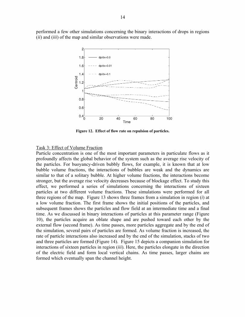
Task 1: Effect of the Strength of the Electric Field Here the goal was to evaluate the effect of strength of the electric field on particle separation. A few simulations concerning a single particle and binary particles were performed where the strength of the electric field was increased incrementally. It was observed that below a threshold, the particles would acquire a steady state shape. However, as the strength of the electric field was increased beyond the threshold, the particles deformed continually and eventually disintegrated to smaller particles. The threshold was found to be a function of the electro-physical properties of the particles and the ambient fluid. In addition to the increased deformation, as the strength of the electric field was increased, the rate of interactions and displacement of the particles also increased. In another set of simulations, instead of changing the strength of the electric field, we varied the initial separation distance of the particles from the electrode while keeping the electric potential constant. Particles whose initial positions were symmetric with respect to the top and the bottom electrodes did not move. However, particles whose initial positions were closer to one of the electrodes moved toward that electrode. The particle speed was inversely proportional to its initial separation distance. Figure 8 shows the results of these tests. Task 2: Effect of Flow Rate Here the goal was to understand the effect of flow rate on phase separation. This was achieved by imposing a constant pressure gradient on the fluid in the horizontal direction. As a result, a parabolic velocity profile was established in the channel which carried the drops in the horizontal direction. Here, the particles deformed as a result of the electric field stresses as well as the shear stresses imposed by the flow field. We performed a series of simulations concerning a single particle and binary interactions of particles. Figure 12 is the result of one of these simulations. The figure shows the trajectories of two particles as a function of time for two different imposed pressure gradients. The trajectories of two particles in a simulation with zero-pressure gradient are also added for comparison. The simulations shown here correspond to region (i) of the map (Figure 2). While two particles in close proximity will repel each other in the range of this parameter in a quiescent fluid, the pressure gradient seems to counterbalance the particle repulsion; i.e., at pressure gradient of 0.01, the particles are pushed together at several instants and at the pressure gradient of 0.1, they are forced to stay together most of the time. We
14
performed a few other simulations concerning the binary interactions of drops in regions (ii) and (iii) of the map and similar observations were made.
Task 3: Effect of Volume Fraction Particle concentration is one of the most important parameters in particulate flows as it profoundly affects the global behavior of the system such as the average rise velocity of the particles. For buoyancy-driven bubbly flows, for example, it is known that at low bubble volume fractions, the interactions of bubbles are weak and the dynamics are similar to that of a solitary bubble. At higher volume fractions, the interactions become stronger, but the average rise velocity decreases because of blockage effect. To study this effect, we performed a series of simulations concerning the interactions of sixteen particles at two different volume fractions. These simulations were performed for all three regions of the map. Figure 13 shows three frames from a simulation in region (i) at a low volume fraction. The first frame shows the initial positions of the particles, and subsequent frames shows the particles and flow field at an intermediate time and a final time. As we discussed in binary interactions of particles at this parameter range (Figure 10), the particles acquire an oblate shape and are pushed toward each other by the external flow (second frame). As time passes, more particles aggregate and by the end of the simulation, several pairs of particles are formed. As volume fraction is increased, the rate of particle interactions also increased and by the end of the simulation, stacks of two and three particles are formed (Figure 14). Figure 15 depicts a companion simulation for interactions of sixteen particles in region (iii). Here, the particles elongate in the direction of the electric field and form local vertical chains. As time passes, larger chains are formed which eventually span the channel height.
Figure 12. Effect of flow rate on repulsion of particles.

15
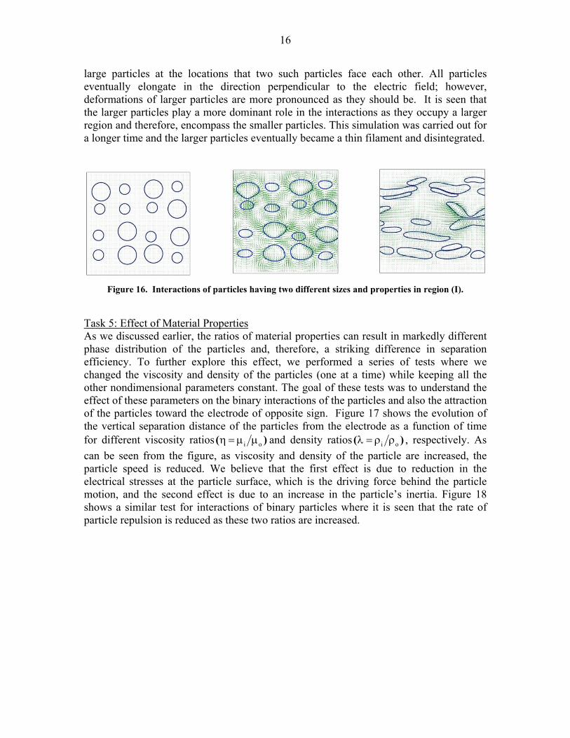
Task 4: Effect of Size Distribution In most of the particulate flows, particles are not of equal size and there is a spectrum of particle sizes. Since the magnitude of the electric and the hydrodynamic forces are proportional to the particle size, particles of different sizes will behave differently under a given flow and electric field conditions. To explore this effect, we performed a series of simulations concerning binary interactions of two unequal-sized particles as well as interactions of sixteen particles of two different sizes. The dynamics in all three regions of the map were explored. Figure 16 shows three frames from one of our simulations corresponding to a run in region (i). The figure shows tip formation on the surface of
Figure 15. Interactions of equal-sized particles having properties in region (III) at a low volume fraction.
Figure 14. Interactions of equal-sized particles having properties in region (II) at a high volume fraction.
Figure 13. Interactions of particles having properties in region (I) at low volume fractions.
16
large particles at the locations that two such particles face each other. All particles eventually elongate in the direction perpendicular to the electric field; however, deformations of larger particles are more pronounced as they should be. It is seen that the larger particles play a more dominant role in the interactions as they occupy a larger region and therefore, encompass the smaller particles. This simulation was carried out for a longer time and the larger particles eventually became a thin filament and disintegrated.
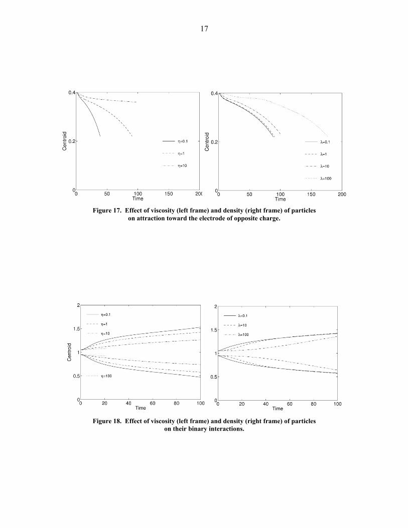
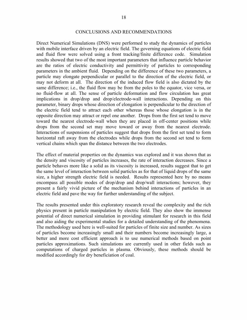
Task 5: Effect of Material Properties As we discussed earlier, the ratios of material properties can result in markedly different phase distribution of the particles and, therefore, a striking difference in separation efficiency. To further explore this effect, we performed a series of tests where we changed the viscosity and density of the particles (one at a time) while keeping all the other nondimensional parameters constant. The goal of these tests was to understand the effect of these parameters on the binary interactions of the particles and also the attraction of the particles toward the electrode of opposite sign. Figure 17 shows the evolution of the vertical separation distance of the particles from the electrode as a function of time for different viscosity ratios i o( )η = μ μ and density ratios i o( )λ = ρ ρ , respectively. As can be seen from the figure, as viscosity and density of the particle are increased, the particle speed is reduced. We believe that the first effect is due to reduction in the electrical stresses at the particle surface, which is the driving force behind the particle motion, and the second effect is due to an increase in the particle’s inertia. Figure 18 shows a similar test for interactions of binary particles where it is seen that the rate of particle repulsion is reduced as these two ratios are increased.
Figure 16. Interactions of particles having two different sizes and properties in region (I).
17
Figure 18. Effect of viscosity (left frame) and density (right frame) of particles on their binary interactions.
Figure 17. Effect of viscosity (left frame) and density (right frame) of particles on attraction toward the electrode of opposite charge.
18
CONCLUSIONS AND RECOMMENDATIONS Direct Numerical Simulations (DNS) were performed to study the dynamics of particles with mobile interface driven by an electric field. The governing equations of electric field and fluid flow were solved using a front tracking/finite difference code. Simulation results showed that two of the most important parameters that influence particle behavior are the ratios of electric conductivity and permittivity of particles to corresponding parameters in the ambient fluid. Depending on the difference of these two parameters, a particle may elongate perpendicular or parallel to the direction of the electric field, or may not deform at all. The direction of the induced flow field is also dictated by the same difference; i.e., the fluid flow may be from the poles to the equator, vice versa, or no fluid-flow at all. The sense of particle deformation and flow circulation has great implications in drop/drop and drop/electrode-wall interactions. Depending on this parameter, binary drops whose direction of elongation is perpendicular to the direction of the electric field tend to attract each other whereas those whose elongation is in the opposite direction may attract or repel one another. Drops from the first set tend to move toward the nearest electrode-wall when they are placed in off-center positions while drops from the second set may move toward or away from the nearest electrode. Interactions of suspensions of particles suggest that drops from the first set tend to form horizontal raft away from the electrodes while drops from the second set tend to form vertical chains which span the distance between the two electrodes. The effect of material properties on the dynamics was explored and it was shown that as the density and viscosity of particles increases, the rate of interaction decreases. Since a particle behaves more like a solid as its viscosity is increased, results suggest that to get the same level of interaction between solid particles as for that of liquid drops of the same size, a higher strength electric field is needed. Results represented here by no means encompass all possible modes of drop/drop and drop/wall interactions; however, they present a fairly vivid picture of the mechanism behind interactions of particles in an electric field and pave the way for further understanding of the subject. The results presented under this exploratory research reveal the complexity and the rich physics present in particle manipulation by electric field. They also show the immense potential of direct numerical simulation in providing stimulant for research in this field and also aiding the experimental studies for a detailed understanding of the phenomena. The methodology used here is well-suited for particles of finite size and number. As sizes of particles become increasingly small and their numbers become increasingly large, a better and more cost efficient approach is to use numerical methods based on point particles approximations. Such simulations are currently used in other fields such as computations of charged particles in plasma. Obviously, these methods should be modified accordingly for dry beneficiation of coal.

19
REFERENCES
Allan, R.S. and Mason, S.G. 1962. “Particle Behavior in Shear and Electric Fields – Deformation and Burst of Fluid Drops.” Proc. Roy. Soc. A., 267: 45-61. Arp, P.A., Foister, R.T., and Mason, S.G. 1980. “Some Electrohydrodynamic Effects in Fluid Dispersions.” Adv. Colloid Interface Sci., 12: 295-356. Baygents, J.C., Rivette, N.J., and Stone, H.A. 1998. “Electrohydrodynamic Deformation and Interaction of Drop Pairs.” J. Fluid Mech., 368: 359-375. Esmaeeli, A. 2005. “Phase Distribution of Bubbly Flows under Terrestrial and Microgravity Conditions.” Fluid Dynamics & Materials Processing (FDMP), 1: 63-80. Esmaeeli, A. and Arpaci, V. 1999. “Thermocapillary-Driven Migration of Bubbles in Shear Flows.” Paper Number FEDSM99-7376. Proceedings of 1999 ASME-FED Summer Meeting. July 18-23, San Francisco, CA. Esmaeeli, A. and Tryggvason, G. 1996. “An Inverse Energy Cascade in Two-Dimensional, Low Reynolds Number Bubbly Flows.” J. Fluid Mech., 314: 315-330. Esmaeeli, A. and Tryggvason, G. 1998. “Direct Numerical Simulations of Bubbly Flows. Part 1. Low Reynolds Number Arrays.” J. Fluid Mech., 377: 313-345. Esmaeeli, A. and Tryggvason, G. 1999. “Direct Numerical Simulations of Bubbly Flows. Part 2. Moderate Reynolds Number Arrays.” J. Fluid Mech., 385: 325-358. Esmaeeli, A. and Tryggvason, G. 2004a. “Computations of Film Boiling. Part I: Numerical Method.” Int. J. Heat Mass Tr., 47: 5463. Esmaeeli, A. and Tryggvason, G. 2004b. “Computations of Film Boiling. Part II: Multi-mode Film Boiling.” Int. J. Heat Mass Tr., 47: 5451. Esmaeeli, A. and Tryggvason, G. 2005. “A Direct Numerical Simulation Study of the Buoyant Rise of Bubbles at O(100) Reynolds Number.” Phys. Fluids, 17, 093303, 1. Feng, J.Q. and Scott, T.C. 1996. “A Computational Analysis of Electrohydrodynamics of a Leaky Dielectric Drop in an Electric Field.” J. Fluid Mech. 311: 289-326. Fernandez, A., Tryggvason, G., Che, J., and Ceccio, S. L. 2005. “The Effect of Electrostatic Forces on the Distribution of Drops in a Channel Flow: Two-dimensional Oblate Drops.” Phys. Fluids, 17, 093302. Ha, J.W. and Yang, S.M. 2000. “Rheological Responses of Oil-in-Oil Emulsions in an Electric Field.” J. Rheol., 44: 235.

20
Kimura, H., Aikawa, K., Masabuchi, Y., Takimoto, J., Koyama, K., and Uemura, T. 1998. “Positive and Negative Electro-Rheological Effect of Liquid Blends.” J. Non-Newtonian Fluid Mech., 76: 199. Melcher, J.R. and Taylor, G.I 1969. “Electrohydrodynamics: A Review of the Role of Interfacial Shear Stresses.” Ann. Rev. Fluid Mech., 1: 111-147. Pan, X.D., McKinley, G.H. 1997. “Characteristics of Electrorheological Responses in an Emulsion System.” J. Colloid Interface Science, 195: 101-113. Rhodes, P.H., Snyder, R.S., and Roberts, G.O. 1989. “Electrohydrodynamic Distortion of Sample Streams in Continuous Flow Electrophoresis.” J. Colloid Interface Sci., 129: 78-90. Saville, D.A. 1997. Electrohydrodynamics: “The Taylor-Melcher Leaky Dielectric Model.” Ann. Rev. Fluid Mech., 29: 27-64. Smith, C.V. and Melcher, J.R. 1967. “Electrohydrodynamically Induced Spatially Periodic Cellular Stokes Flow.” Phys. Fluids, 10: 2315-2322. Sherwood, J.D. 1998. “Break up of Fluid Droplets in Electric and Magnetic Fields.” J. Fluid Mech., 188: 133-146. Taylor, G.I. 1966. “Studies in Electrohydrodynamics: I. The Circulation Produced in a Drop by an Electric Field.” Proc. Roy. Soc. A, 291: 159-167. Torza, S., Cox, R.G., and Mason, S.G. 1971 “Electrohydrodynamic Deformation and Burst of Liquid Drops.” Philos. Trans. R. Soc. London, Ser. A, 269: 295-319. Tsukada, T., Katayama, T., Ito, Y., and Hozawa, M. 1993. “Theoretical and Experimental Studies of Circulations Inside and Outside a Deformed Drop under a Uniform Electric Field.” J. Chem. Eng. Japan, 26: 698-703.
21
DISCLAIMER STATEMENT
This report was prepared by Dr. Asghar Esmaeeli of Southern Illinois University Carbondale, with support, in part, by grants made possible by the Illinois Department of Commerce and Economic Opportunity through the Office of Coal Development and the Illinois Clean Coal Institute. Neither Dr. Asghar Esmaeeli, Southern Illinois University, nor any of its subcontractors, nor the Illinois Department of Commerce and Economic Opportunity, Office of Coal Development, the Illinois Clean Coal Institute, nor any person acting on behalf of either: (A) Makes any warranty of representation, express or implied, with respect to the accuracy, completeness, or usefulness of the information contained in this report, or that the use of any information, apparatus, method, or process disclosed in this report may not infringe privately-owned rights; or (B) Assume any liabilities with respect to the use of, or for damages resulting from the use of, any information, apparatus, method or process disclosed in this report.
References herein to any specific commercial product, process, or service by trade name, trademark, manufacturer, or otherwise, does not necessarily constitute or imply its endorsement, recommendation, or favoring; nor do the views and opinions of authors expressed herein necessarily state or reflect those of the Illinois Department of Commerce and Economic Opportunity, Office of Coal Development, or the Illinois Clean Coal Institute.
Notice to Journalists and Publishers: If you borrow information from any part of this report, you must include a statement about the state of Illinois’ support of this project.


![Vega: Nonlinear FEM Deformable Object Simulatorrun.usc.edu/vega/SinSchroederBarbic2012.pdf · Vega: Nonlinear FEM Deformable Object Simulator ... (CalculiX [DW]) deformable ... J.](https://static.fdocuments.in/doc/165x107/5aecb8f27f8b9a3b2e8f8865/vega-nonlinear-fem-deformable-object-nonlinear-fem-deformable-object-simulator.jpg)