FUNCTIONAL DESCRIPTION UMC22 - ABB Ltd · Doc. no. Lang. Rev. ind. Page ABB AB 3AST 001 599D001 en...
37
We reserve all rights in this document and in the information contained therein. Reproduction, use or disclosure to third parties without express authority is strictly forbidden. ABB Prep. PA/R/ Bengt Persson 10-11-30 Function Description No. of p. Appr. PA/R/ Bengt Persson Approved 37 Resp. dept. PA/R UMC22 Functional Description Doc. no. Lang. Rev. ind. Page ABB AB 3AST 001 599D001 en D 1 FUNCTIONAL DESCRIPTION UMC22 Universal Motor Controller
-
Upload
phungquynh -
Category
Documents
-
view
232 -
download
3
Transcript of FUNCTIONAL DESCRIPTION UMC22 - ABB Ltd · Doc. no. Lang. Rev. ind. Page ABB AB 3AST 001 599D001 en...

We reserve all rights in this document and in the information contained therein. Reproduction, use or disclosure to third parties without express authority is strictly forbidden. ABB
Prep. PA/R/ Bengt Persson 10-11-30 Function Description No. of p.
Appr. PA/R/ Bengt Persson Approved 37
Resp. dept. PA/R
UMC22 Functional Description
Doc. no. Lang. Rev. ind. Page
ABB AB 3AST 001 599D001 en D 1
FUNCTIONAL DESCRIPTION
UMC22 Universal Motor Controller
Functional Unit UMC22 Functional Description
Doc. no. Lang. Rev. ind. Page
ABB AB 3AST 001 599D001 en D 2
Contents
1 General ..................................................................................................................... 4
2 Configuration ........................................................................................................... 4
3 Function Block UMC22 ............................................................................................ 5
4 UMC22 Datatypes..................................................................................................... 8
4.1 UMC22_InPar............................................................................................... 8
4.2 UMC22_OutPar............................................................................................ 9
4.3 UMC22_Opr ............................................................................................... 10
5 Function.................................................................................................................. 11
5.1 Basic Properties ......................................................................................... 11
5.2 Control Modes............................................................................................ 11
5.2.1 JOG.............................................................................................. 11
5.2.2 LOCAL.......................................................................................... 12
5.2.3 MANUAL....................................................................................... 13
5.2.4 EXTERNAL 1 and EXTERNAL 2 .................................................. 13
5.2.5 DISABLED.................................................................................... 13
5.3 Ready for Start ........................................................................................... 13
5.4 Start-up ...................................................................................................... 13
5.5 lnterlocks.................................................................................................... 14
5.6 Start and Stop ............................................................................................ 14
5.6.1 Start and Stop Order at Different Motor Control Modes................. 15
5.6.2 Start Order Selection .................................................................... 15
5.6.2.1 Control mode JOG .......................................................... 16
5.6.2.2 Control mode LOCAL...................................................... 16
5.6.2.3 Control mode MAN.......................................................... 16
5.6.2.4 Control mode Ext1/Ext2 .................................................. 16
5.6.2.5 Change of Direction/Speed ............................................. 16
5.6.2.6 Control mode DISABLE................................................... 16
5.6.2.7 Control mode Panel Mode............................................... 16
5.7 Fault Evaluation in the Control Circuit......................................................... 16
5.8 Supervision of Motor Current...................................................................... 17
5.9 Interaction Window..................................................................................... 17
5.9.1 UMC22 Interaction Window .......................................................... 17
5.9.2 General Parameters ..................................................................... 17
5.9.3 Order Block................................................................................... 18
5.9.4 Alarm and Event Block.................................................................. 18
5.9.5 Interlock Settings .......................................................................... 19
5.9.6 Current settings ............................................................................ 20
5.9.7 Texts............................................................................................. 21
5.9.8 Maintenance ................................................................................. 21
6 Operator Functions................................................................................................ 23
6.1 Presentation ............................................................................................... 23
6.1.1 Display elements .......................................................................... 23
6.1.1.1 Object display ................................................................. 24
6.1.1.2 Process display............................................................... 24
6.1.1.3 Diagnostic display ........................................................... 25
6.1.1.4 Diagnostic display Configuration ..................................... 25
6.1.1.5 Interlock display .............................................................. 25
6.1.2 Time-logged Properties................................................................. 26
6.2 Faceplate (Dialog) ...................................................................................... 27
6.3 Alarm and Event Handling.......................................................................... 29

Functional Unit UMC22 Functional Description
Doc. no. Lang. Rev. ind. Page
ABB AB 3AST 001 599D001 en D 3
6.3.1 General......................................................................................... 29
6.3.2 Alarm and Event Message............................................................ 30
6.3.3 Diagnostic events ......................................................................... 31
6.4 Faceplate tabs............................................................................................ 33
6.4.1 Alarm and Event blocking ............................................................. 33
6.4.2 Limits ............................................................................................ 33
6.4.3 Info ............................................................................................... 34
6.4.4 Maintenance................................................................................. 34
7 Profibus Device Object type ABB UMC 22 ........................................................... 35
7.1 Function Block UMC22_DI ......................................................................... 35

Functional Unit UMC22 Functional Description
Doc. no. Lang. Rev. ind. Page
ABB AB 3AST 001 599D001 en D 4
1 General
UMC22 is a functional unit designed for the control of motors in different processes.
The functional unit is standardised to a high degree to simplify the work of designing presentation, dialog and control logic. The unit has many optional capabilities, which increase its operational flexibility. UMC22 normally performs its control function without help from other elements.
UMC22 is used in the control of motors from OperateIT
Operator Station, control desks or
control organs at the motor itself. The motor can be controlled from a master control function (e.g. group start, level regulation from level gauges etc).
2 Configuration
UMC22 like other functional units is built up of two parts:
• A Function Block, which is handled in the same way as other Function Blocks in the ABB Controller 800M range of products. Figure 3.1 illustrates the terminals on the function block.
• A section for operator functions, which consists of presentation and order
functions. Data and parameters from the process are presented on an OperateIT
Operator Station. The keyboard of the OperateIT
Operator Station is used by the operator to enter commands which control the operation of the functional unit. The response to the operator's intervention is shown on the display screen of the
OperateIT
Operator Station. The application work for this part is normally limited to the arrangement of the display. Figure 2.1 shows the structure of the functional unit.
Figure 2-1. The Structure of the Functional Unit
MOTOR CONTROL CORE
- start/stop logic
- interlockings
- current calculation
Profibus Interface
HSI INTERFACE
VDU Op. Panel Local
Comm. Interface N/A P
ARAMETERS
DIAGN.
- alarms
(fault,
warning)
- events
- loggers
HSI
PROCESS OBJECT

Functional Unit UMC22 Functional Description
Doc. no. Lang. Rev. ind. Page
ABB AB 3AST 001 599D001 en D 5
3 Function Block UMC22
FUNCTION OF INPUT TERMINALS UMC22 FUNCTION OF OUTPUT TERMINALS
Object name Name
Object description Description
Enable object Enable
Connection to Profibus Variable ---------------- MCC ----------------
UMC22 unit status UMCUnitStatus NoInt No Interlocks
Profibus status UnitStatus NoFwdInt No Interlocks in Forward direction
Enable reverse direction Reversing NoRevInt No Interlocks in Reverse direction
Enable control circuit alarm ME NoICInt No Safety Interlocks (IC)
Control voltage M1 NoFwdIBInt No Process Interlocks (IB) in Forward direction
Overload M2 NoRevIBInt No Process Interlocks (IB) in Reverse direction
Motor breaker M3 NoFwdIAInt No Sequence Interlocks (IA) in Forward direction
Emergency stop M4 NoRevIAInt No Sequence Interlocks (IA) in Reverse direction
Short Circuit M5 Trip Trip
Safety Interlock 1 IC1 Blk Standby
Safety Interlock 2 IC2 RFS Ready for start
Safety Interlocks ICs SO1 Start order forward
Process Interlock 1 IB1 SO1P Start order forward pulse (during T1 time)
Process Interlock 2 IB2 SO2 Start order reverse
Process Interlock 3 IB3 SO2P Start order reverse pulse (during T1 time)
Process Interlock 4 IB4 StartWarn Start warning
Forward Process Interlocks FwdIBs SO1Ack Start forward acknowledgement
Reverse Process Interlocks RevIBs SO2Ack Start reverse acknowledgement
Sequence Interlock 1 IA1 Ack1 Main contactor acknowledge forward
Sequence Interlock 2 IA2 Ack2 Main contactor acknowledge reverse
Forward Sequence Interlocks FwdIAs Run Running
Reverse Sequence Interlocks RevIAs TestMode Test mode
Start order pulse Time T1 PanelMode Panel mode
Supervision Time T2 JogInd Jog mode
Run interlock delay Time T3 LocalInd Local mode
Start warning time TWarn ManInd Man mode
Start forward order in E1 mode E1Fwd E1Ind E1 mode
Start reverse order in E1 mode E1Rev E2Ind E2 mode
Start forward order in E2 mode E2Fwd NormCurr Normal current (%)
Start reverse order in E2 mode E2Rev Curr Actual current (%)
Stop order in external mode Stop Current Actual current (in unit)
Order mode to Jog JogEnbl NoOfStart Number of start
Forward Start order in Jog mode JogFwd RunTime Running time (in minutes)
Reverse Start order in Jog mode JogRev OutPar Out Parameter
Jog start hold function JogFunc Opr Operator order
Order mode to Local LEnbl
Forward Start order in Local mode L1
Reverse Start order in Local mode L2
Local Stop order LStop
Order mode to Man SeqMan
Order mode to E1 SeqE1
Order mode to E2 SeqE2
Set Test Mode from MCC SetTest
Run Interlock 1 RunInt1
Run Interlock 2 RunInt2
Function for Run Interlock 2 RunInt2F
Block alarm AlcBlk
Acknowledge alarm AlarmAck
In Parameter InPar

Functional Unit UMC22 Functional Description
Doc. no. Lang. Rev. ind. Page
ABB AB 3AST 001 599D001 en D 6
Event name EventName Figure 3-1. Function Block, Complete symbol
Table 3-1 below illustrates the default properties of each terminal of UMC22 function block.
Name Data Type
Attributes Direction FD
Port Initial value Description
Name string coldretain in yes 'UMC22' Object name
Description string coldretain in yes 'Descr' Object description
Enable bool coldretain in yes true Enable object
MCC UMC22_DP
in_out yes Communication with MCC
UMCUnitStatus HwStatus by_ref in yes UMC22 unit status
UnitStatus dint retain in yes Profibus status
Reversing bool coldretain in yes false Enable reverse direction
ME bool retain in yes true Enable control circuit alarm
M1 bool retain in yes true Control voltage
M2 bool retain in yes true Overload
M3 bool retain in yes true Motor breaker
M4 bool retain in yes true Emergency stop
M5 bool retain in yes true Short Circuit
IC1 bool retain in yes true Safety Interlock 1
IC2 bool retain in yes true Safety Interlock 2
ICs ICConn by_ref in yes Safety Interlocks
IB1 bool retain in yes true Process Interlock 1
IB2 bool retain in yes true Process Interlock 2
IB3 bool retain in yes true Process Interlock 3
IB4 bool retain in yes true Process Interlock 4
FwdIBs IBConn by_ref in yes Forward Process Interlocks
RevIBs IBConn by_ref in yes Reverse Process Interlocks
IA1 bool retain in yes true Sequence Interlock 1
IA2 bool retain in yes true Sequence Interlock 2
FwdIAs IAConn by_ref in yes Forward Sequence Interlocks
RevIAs IAConn by_ref in yes Reverse Sequence Interlocks
T1 time coldretain in yes 2s Start order pulse Time
T2 time coldretain in yes 4s Supervision Time
T3 time coldretain in yes 5s Run interlock delay Time
TWarn time coldretain in yes 0s Start warning time
E1Fwd bool retain in yes Start forward order in E1 mode
E1Rev bool retain in yes Start reverse order in E1 mode
E2Fwd bool retain in yes Start forward order in E2 mode
E2Rev bool retain in yes Start reverse order in E2 mode
Stop bool retain in yes true Stop order in external mode
JogEnbl bool retain in yes Order mode to Jog
JogFwd bool retain in yes Forward Start order in Jog mode
JogRev bool retain in yes Reverse Start order in Jog mode
JogFunc bool retain in yes Jog start hold function
LEnbl bool retain in yes Order mode to Local
L1 bool retain in yes Forward Start order in Local mode
L2 bool retain in yes Reverse Start order in Local mode
LStop bool retain in yes true Local Stop order
SeqMan bool retain in yes Order mode to Man
SeqE1 bool retain in yes Order mode to E1
SeqE2 bool retain in yes Order mode to E2
SetTest dint coldretain in yes -1 Set Test Mode from MCC (0 = DI0, 1 = DI1, 2 = DI2, 3 = DI3, 4 = DI4, 5 = DI5)
RunInt1 bool retain in yes true Run Interlock 1
RunInt2 bool retain in yes true Run Interlock 2
RunInt2F bool retain in yes Function for Run Interlock 2
AlcBlk bool retain in yes Block alarm
AlarmAck bool retain in yes Acknowledge alarm
InPar UMC22_InPar
by_ref in yes In Parameter

Functional Unit UMC22 Functional Description
Doc. no. Lang. Rev. ind. Page
ABB AB 3AST 001 599D001 en D 7
Name Data Type
Attributes Direction FD
Port Initial value Description
EventName string coldretain in yes '||UMC22_' Event name
NoInt bool retain out yes No Interlocks
NoFwdInt bool retain out yes No Interlocks in Forward direction
NoRevInt bool retain out yes No Interlocks in Reverse direction
NoICInt bool retain out yes No Safety Interlocks (IC)
NoFwdIBInt bool retain out yes No Process Interlocks (IB) in Forward direction
NoRevIBInt bool retain out yes No Process Interlocks (IB) in Reverse direction
NoFwdIAInt bool retain out yes No Sequence Interlocks (IA) in Forward direction
NoRevIAInt bool retain out yes No Sequence Interlocks (IA) in Reverse direction
Trip bool retain out yes Trip
Blk bool retain out yes Standby
RFS bool retain out yes Ready for start
SO1 bool retain out yes Start order forward
SO1P bool retain out yes Start order forward pulse (during T1 time)
SO2 bool retain out yes Start order reverse
SO2P bool retain out yes Start order reverse pulse (during T1 time)
StartWarn bool retain out yes Start warning
SO1Ack bool retain out yes Start forward acknowledgement
SO2Ack bool retain out yes Start reverse acknowledgement
Ack1 bool retain out yes Main contactor acknowledge forward
Ack2 bool retain out yes Main contactor acknowledge reverse
Run bool retain out yes Running
TestMode bool retain out yes Test mode
PanelMode bool retain out yes Panel mode
JogInd bool retain out yes Jog mode
LocalInd bool retain out yes Local mode
ManInd bool retain out yes Man mode
E1Ind bool retain out yes E1 mode
E2Ind bool retain out yes E2 mode
NormCurr real retain out yes Normal current (%)
Curr real retain out yes Actual current (%)
Current real retain out yes Actual current (in unit)
NoOfStart dint coldretain out yes Number of start
RunTime real coldretain out yes Running time (in minutes)
OutPar UMC22_OutPar
by_ref out yes Out Parameter
Opr UMC22_Opr
by_ref out yes Operator order
Table 3-1 Terminal Properties

Functional Unit UMC22 Functional Description
Doc. no. Lang. Rev. ind. Page
ABB AB 3AST 001 599D001 en D 8
4 UMC22 Datatypes
4.1 UMC22_InPar
Name Data Type Attributes Initial value
ISP value
Description
Class dint coldretain 500 AE class
Severity dint coldretain 1000 AE severity
InitMode dint coldretain 5 Init mode (5 = Man ; 7 = E1 ; 8 = E2)
JogBlk bool coldretain false Block operator order Jog mode
LocalBlk bool coldretain false Block operator order Local mode
ManBlk bool coldretain false Block operator order Man mode
E1Blk bool coldretain false Block operator order E1 mode
E2Blk bool coldretain false Block operator order E2 mode
StartFwdBlk bool coldretain false Block operator order Start Forward command
StartRevBlk bool coldretain false Block operator order Start Reverse command
StopBlk bool coldretain false Block operator order Stop command
AlcBlkEvBlk bool coldretain true Block event for AlcBlk
LEnblEvBlk bool coldretain true Block event for LEnbl
JogEnblEvBlk bool coldretain true Block event for JogEnbl
SeqManEvBlk bool coldretain true Block event for SeqMan
SeqE1EvBlk bool coldretain true Block event for SeqE1
SeqE2EvBlk bool coldretain true Block event for SeqE2
PanelEvBlk bool coldretain true Block event for Panel
ExtStartFwdEvBlk bool coldretain true Block event for ExtStartFwd
ExtStartRevEvBlk bool coldretain true Block event for ExtStartRev
ExtStopEvBlk bool coldretain true Block event for ExtStop
IABlockNotExtMode bool coldretain true IA blocked when not in E1 or E2 mode
IA1 IAInParType1 coldretain Configuration for IA1
IA2 IAInParType1 coldretain Configuration for IA2
FwdIAs1 IAInParType1 coldretain Configuration for FwdIAs.IA1
FwdIAs2 IAInParType1 coldretain Configuration for FwdIAs.IA2
RevIAs1 IAInParType1 coldretain Configuration for RevIAs.IA1
RevIAs2 IAInParType1 coldretain Configuration for RevIAs.IA2
IB1 IBInParType1 coldretain Configuration for IB1
IB2 IBInParType1 coldretain Configuration for IB2
IB3 IBInParType1 coldretain Configuration for IB3
IB4 IBInParType1 coldretain Configuration for IB4
FwdIBs1 IBInParType1 coldretain Configuration for FwdIBs.IB1
FwdIBs2 IBInParType1 coldretain Configuration for FwdIBs.IB2
FwdIBs3 IBInParType1 coldretain Configuration for FwdIBs.IB3
FwdIBs4 IBInParType1 coldretain Configuration for FwdIBs.IB4
FwdIBs5 IBInParType1 coldretain Configuration for FwdIBs.IB5
FwdIBs6 IBInParType1 coldretain Configuration for FwdIBs.IB6
FwdIBs7 IBInParType1 coldretain Configuration for FwdIBs.IB7
FwdIBs8 IBInParType1 coldretain Configuration for FwdIBs.IB8
RevIBs1 IBInParType1 coldretain Configuration for RevIBs.IB1
RevIBs2 IBInParType1 coldretain Configuration for RevIBs.IB2
RevIBs3 IBInParType1 coldretain Configuration for RevIBs.IB3
RevIBs4 IBInParType1 coldretain Configuration for RevIBs.IB4
RevIBs5 IBInParType1 coldretain Configuration for RevIBs.IB5
RevIBs6 IBInParType1 coldretain Configuration for RevIBs.IB6
RevIBs7 IBInParType1 coldretain Configuration for RevIBs.IB7
RevIBs8 IBInParType1 coldretain Configuration for RevIBs.IB8
IC1 ICInParType1 coldretain Configuration for IC1
IC2 ICInParType1 coldretain Configuration for IC2
ICs1 ICInParType1 coldretain Configuration for ICs.IC1
ICs2 ICInParType1 coldretain Configuration for ICs.IC2
RatedCurr real coldretain 100.0 Rated current
NormalCurr real coldretain 50.0 Normal current
CurrUnit string coldretain 'A' Current unit

Functional Unit UMC22 Functional Description
Doc. no. Lang. Rev. ind. Page
ABB AB 3AST 001 599D001 en D 9
Name Data Type Attributes Initial value
ISP value
Description
ShowCurrent bool coldretain false Show current presentation
AEConfigCommErr dint coldretain 1 AE configuration for Communication Error
AEConfigFault dint coldretain 1 AE configuration for Fault
AEConfigM1 dint coldretain 1 AE configuration for M1
AEConfigM2 dint coldretain 1 AE configuration for M2
AEConfigM3 dint coldretain 1 AE configuration for M3
AEConfigM4 dint coldretain 1 AE configuration for M4
AEConfigM5 dint coldretain 1 AE configuration for M5
AEConfigMCErr dint coldretain 1 AE configuration for Main Contactor Error
AEConfigWarning dint coldretain 1 AE configuration for Warning
AEConfigRInt1 dint coldretain 0 AE configuration for Run Interlock 1
AEConfigRInt2 dint coldretain 0 AE configuration for Run Interlock 2
EnNoOfStartCounter bool coldretain false Enable number of start counter
EnRunTimeCounter bool coldretain false Enable running time counter
4.2 UMC22_OutPar
Name Data Type Attributes Initial value
ISP value
Description
AlarmBlk bool retain Alarm blocked
IntlkBlk bool retain Interlock blocked
IntlkBlkActive bool retain Interlock blocked active
EnOverrideAll bool retain Override All button enabled
Mode dint retain Active mode
NormalMode bool retain Normal mode (Active mode = Init mode)
IA1Ind bool retain IA1 interlocked
IA2Ind bool retain IA2 interlocked
IB1Ind bool retain IB1 interlocked
IB2Ind bool retain IB2 interlocked
IB3Ind bool retain IB3 interlocked
IB4Ind bool retain IB4 interlocked
IC1Ind bool retain IC1 interlocked
IC2Ind bool retain IC2 interlocked
FwdIAs1Ind bool retain FwdIAs.IA1 interlocked
FwdIAs2Ind bool retain FwdIAs.IA2 interlocked
FwdIBs1Ind bool retain FwdIBs.IB1 interlocked
FwdIBs2Ind bool retain FwdIBs.IB2 interlocked
FwdIBs3Ind bool retain FwdIBs.IB3 interlocked
FwdIBs4Ind bool retain FwdIBs.IB4 interlocked
FwdIBs5Ind bool retain FwdIBs.IB5 interlocked
FwdIBs6Ind bool retain FwdIBs.IB6 interlocked
FwdIBs7Ind bool retain FwdIBs.IB7 interlocked
FwdIBs8Ind bool retain FwdIBs.IB8 interlocked
ICs1Ind bool retain ICs.IC1 interlocked
ICs2Ind bool retain ICs.IC2 interlocked
RevIAs1Ind bool retain RevIAs.IA1 interlocked
RevIAs2Ind bool retain RevIAs.IA2 interlocked
RevIBs1Ind bool retain RevIBs.IB1 interlocked
RevIBs2Ind bool retain RevIBs.IB2 interlocked
RevIBs3Ind bool retain RevIBs.IB3 interlocked
RevIBs4Ind bool retain RevIBs.IB4 interlocked
RevIBs5Ind bool retain RevIBs.IB5 interlocked
RevIBs6Ind bool retain RevIBs.IB6 interlocked
RevIBs7Ind bool retain RevIBs.IB7 interlocked
RevIBs8Ind bool retain RevIBs.IB8 interlocked
CommErr AlarmInd retain Alarm Indication for CommErr
Fault AlarmInd retain Alarm Indication for Fault
M1 AlarmInd retain Alarm Indication for M1
M2 AlarmInd retain Alarm Indication for M2
M3 AlarmInd retain Alarm Indication for M3

Functional Unit UMC22 Functional Description
Doc. no. Lang. Rev. ind. Page
ABB AB 3AST 001 599D001 en D 10
Name Data Type Attributes Initial value
ISP value
Description
M4 AlarmInd retain Alarm Indication for M4
M5 AlarmInd retain Alarm Indication for M5
MCErr AlarmInd retain Alarm Indication for MCErr
RInt1 AlarmInd retain Alarm Indication for RInt1
RInt2 AlarmInd retain Alarm Indication for RInt2
Warning AlarmInd retain Alarm Indication for Warning
Dir bool retain Running direction (0 = forward, 1 = reverse)
DirChange bool retain Change of running direction
LastStop dint retain Reason for last stop
StartTime time retain Actual starting time
StopTime time retain Actual stopping time
RevLockOut bool retain Reverse lock out
4.3 UMC22_Opr
Name Data Type Attributes Initial value
ISP value
Description
BlockAlarm bool retain Operator block alarms
Jog bool retain Operator order Jog mode
Local bool retain Operator order Local mode
Man bool retain Operator order Manual mode
E1 bool retain Operator order E1 mode
E2 bool retain Operator order E2 mode
StartFwd bool retain Operator order Start Forward command
StartRev bool retain Operator order Start Reverse command
Stop bool retain Operator order Stop command
Reset bool retain Operator order Reset command
SelfTest bool retain Operator order Self Test
EmergencyStart bool retain Operator order Emergency Start
OverrideAll bool retain Operator override all interlocks
IB1Override bool retain Operator override IB1 interlock
IB2Override bool retain Operator override IB2 interlock
IB3Override bool retain Operator override IB3 interlock
IB4Override bool retain Operator override IB4 interlock
FwdIBs1Override bool retain Operator override FwdIBs.IB1 interlock
FwdIBs2Override bool retain Operator override FwdIBs.IB2 interlock
FwdIBs3Override bool retain Operator override FwdIBs.IB3 interlock
FwdIBs4Override bool retain Operator override FwdIBs.IB4 interlock
FwdIBs5Override bool retain Operator override FwdIBs.IB5 interlock
FwdIBs6Override bool retain Operator override FwdIBs.IB6 interlock
FwdIBs7Override bool retain Operator override FwdIBs.IB7 interlock
FwdIBs8Override bool retain Operator override FwdIBs.IB8 interlock
RevIBs1Override bool retain Operator override RevIBs.IB1 interlock
RevIBs2Override bool retain Operator override RevIBs.IB2 interlock
RevIBs3Override bool retain Operator override RevIBs.IB3 interlock
RevIBs4Override bool retain Operator override RevIBs.IB4 interlock
RevIBs5Override bool retain Operator override RevIBs.IB5 interlock
RevIBs6Override bool retain Operator override RevIBs.IB6 interlock
RevIBs7Override bool retain Operator override RevIBs.IB7 interlock
RevIBs8Override bool retain Operator override RevIBs.IB8 interlock
IA1Override bool retain Operator override IA1 interlock
IA2Override bool retain Operator override IA2 interlock
FwdIAs1Override bool retain Operator override FwdIAs.IA1 interlock
FwdIAs2Override bool retain Operator override FwdIAs.IA2 interlock
RevIAs1Override bool retain Operator override RevIAs.IA1 interlock
RevIAs2Override bool retain Operator override RevIAs.IA2 interlock
ResetCounter bool retain Order reset counter

Functional Unit UMC22 Functional Description
Doc. no. Lang. Rev. ind. Page
ABB AB 3AST 001 599D001 en D 11
5 Function
5.1 Basic Properties
The UMC22 functional unit is designed for control of motors.
UMC22 units consist of the following basic functions.
• Supervision of control circuits
• Evaluation of interlocks
• Control of on/off
• Supervision of motor current
• Running of tests from the motor site
• Control from the local operator's panel
• Manual/External running
• Supervision of operations via OperateIT
Operator Station
5.2 Control Modes
UMC22 is intended for control from OperateIT
Operator Station, i.e. from a central control
room. However, it is also possible to select other modes of control and thus control UMC22 from other locations.
All the control modes can be selected from the central operator station. The LOCAL control mode may also be selected from the local control station or MCC.
The different modes of control are as follows:
• Jog
• Local
• Manual
• External 1
• External 2
• Test
By selecting control mode, the operator decides from which location the motor is to be
controlled. All control modes may be selected through dialog in OperateIT
Operator Station. The LOCAL control mode may also be selected from the local control station through the Function Block input :LEnbl, provided that the current control mode is neither JOG, nor DISABLE.
For the different control modes, UMC22 is controlled as follows. For a summary of the control modes, see Table 4-1.
5.2.1 JOG
The control mode JOG is suitable for testing the motor in the field. The motor is supposed to be controlled from a stop/start station adjacent to the motor. Control from other locations is blocked.

Functional Unit UMC22 Functional Description
Doc. no. Lang. Rev. ind. Page
ABB AB 3AST 001 599D001 en D 12
The supervision of interlocks is limited. Only the safety interlocks :IC1 and :IC2 as well as faults in the control voltage chain (the inputs :M1 - :M5) prevent starting.
The motor is started and stopped through the inputs :JogFwd, :JogRev and :JogFunc.
:JogFwd, :JogRev, Start order from field-mounted start/stop station
:JogFunc, Stop/Hold function from field-mounted start/stop station
The function of these inputs is set out in tabular form below.
:JogFwd/JogRev :JogFunc
0 0 Stop order.
0 1 No change.
1 0 Start and stop order in :JogFwd/JogRev input.
1 1 Start order on :JogFwd/JogRev and stop order on :JogFunc.
When :JogFunc=1, the motor is stopped by breaking the control voltage chain, i.e. signified by any of the :M1 - :M5 inputs going low.
5.2.2 LOCAL
The motor is controlled from a local desk or panel. Control from other locations is blocked.
LOCAL control mode, like other points of control, may be selected from OperateIT
Operator Station. In addition, LOCAL control mode may be selected from the local control panel through the input :LEnbl as follows:
:LEnbl = 1: The control mode is LOCAL, as long as the OperateIT
Operator Station operator does not request JOG or STAND BY. All other control modes are blocked and :LEnbl must be released before a mode change can occur.
LEnbl -> 0: UMC22 resumes the previous or the latest control mode called for from
OperateIT
Operator Station.
The operator controls the motor through the inputs :L1, :L2 and :LStop.
:LStop Local stop order (active low)
:L1 Local start order forward
:L2 Local start order reverse
The function of these inputs is set out in tabular form below.
:L1/L2 :Lstart
0 X Stop order. Note In order for the motor to start when LStop has been low, LStop must be set high and L1 or L2 must make a low-to-high transition
1 0 No change
1 1 Start order

Functional Unit UMC22 Functional Description
Doc. no. Lang. Rev. ind. Page
ABB AB 3AST 001 599D001 en D 13
5.2.3 MANUAL
The motor is controlled from OperateIT
Operator Station. Control from other locations is blocked. This is the default control mode. To start, the operator has to press the key FWD or REV. To stop the motor, the key STOP has to be pressed.
5.2.4 EXTERNAL 1 and EXTERNAL 2
The motor is controlled from external signals, e.g. from a process signal. Control from other locations is blocked. This mode is e.g. used for on/off control of levels and for automatic start up and shutdown of belt conveyors etc.
EXTERNAL 2 functions in exactly the same way as EXTERNAL 1. EXTERNAL 2 is used when the motor is to be controlled by Level 2 application software e.g. Auto Series Software.
The function is enabled by inputs :SeqE1 and :SeqE2.
The process controls the motor through the inputs :E1Fwd, :E1Rev, :E2Fwd, :E2Rev and
:Stop. The operator is able to stop the motor by issuing stop order from OperateIT
Operator Station. The control mode then changes to Manual, to prevent the motor from being restarted.
:Stop Stop order (active low)
:E1(2)Fwd Start order forward
:E1(2)Rev Start order reverse
The function of these inputs is set out in tabular form below:
:Stop :E1(2)Fwd/Rev
0 X Stop order
1 0 -> 1 Start order
:E1(2)Fwd/Rev are dynamic inputs, i.e. they trigger on the rising edge.
5.2.5 DISABLED
The motor is stopped and all orders to it are blocked. Used to take the motor Out of Service.
5.3 Ready for Start
Ready for start means that all the interlocks are satisfied, that there are no alarms and that the control mode is not JOG or that the control is DISABLED.
Ready for start is indicated by the UMC22 displays in the OperateIT
Operator
Station and by the output terminal :RFS (Ready For Start) in the function block.
5.4 Start-up
An initialisation phase begins at start of the AC800M system.
The result of this becomes:
The outputs are reset (to zero) except for the ManInd terminal, which is set (to 1).
Manual is the default control mode at system initialisation. With an additional circuit it is possible to force the control mode to other modes at system initialisation.

Functional Unit UMC22 Functional Description
Doc. no. Lang. Rev. ind. Page
ABB AB 3AST 001 599D001 en D 14
5.5 lnterlocks
The motor control can be interlocked by signals from the process and also by signals from the control logic. The interlocks are divided into four groups with the following designations and functions.
Safety Interlocks, which interlock the object for safety purposes. The two safety interlocks, :IC1 and :IC2, cannot be blocked.
Process Interlocks. There are 4 normal process interlocks, :IB1 to :IB4. All four interlocks can be configured to accept blocking by the operator. All four interlocks can also be configured as start interlocks. A start interlock will prevent the motor from starting, but does not stop a running motor.
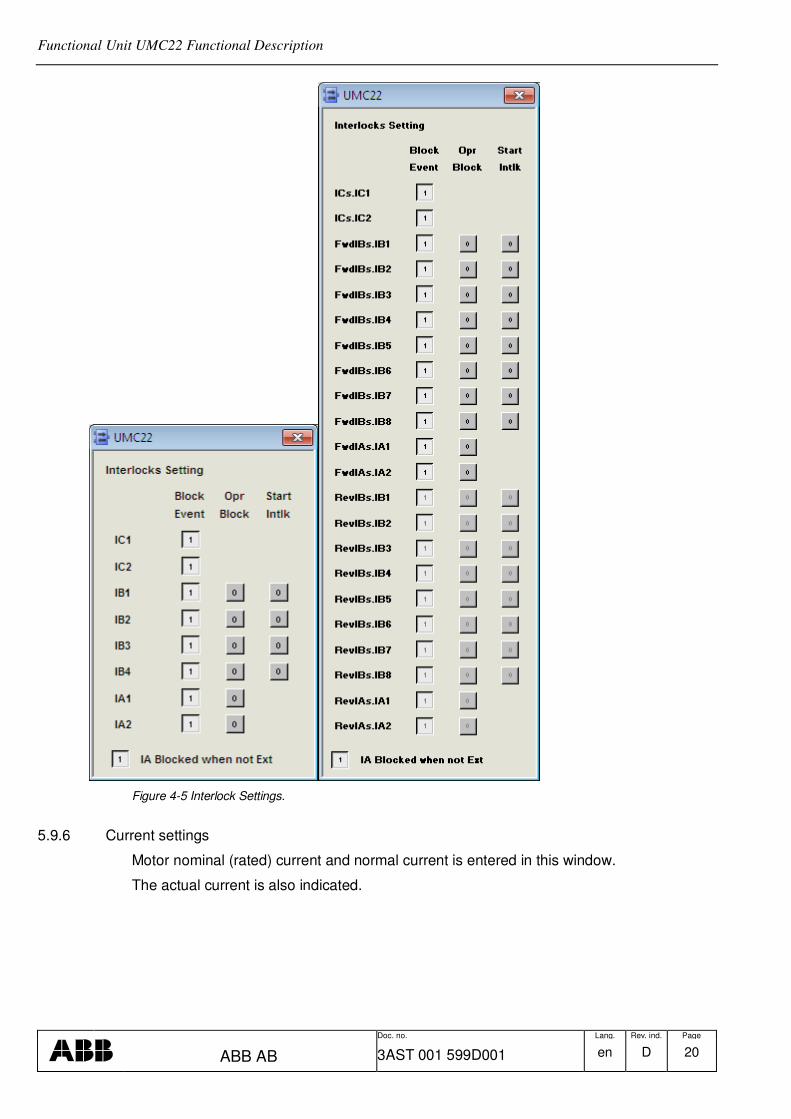
External (Sequence) Interlocks. Interlocks on terminals :IA1 and :IA2 are used if the object is to be interlocked against other objects such as a pump motor or a group start or other conditions in an automatic sequence. These interlocks are configurable as blocked or not when not in E1 resp. E2 mode and the interlocks are not included in the conditions for indication of Ready for start.
If IA blocked when not Ext is equal to 1
Motor interlocked if IA1 is 0 and the motor is in E1 mode
Motor interlocked if IA2 is 0 and the motor is in E2 mode
If IA blocked when not Ext is equal to 0
Motor interlocked if IA1 or IA2 is 0 and the motor is in Man, E1,E2 or Local mode
Run Interlocks. The inputs :RunInt1 and :RunInt2 are intended for connection to operation monitors to obtain tripping or alarm in the event of faults. The inputs are to be TRUE when the equipment is faultless. In order to allow the motor to reach operational speed, RunInt1 and RunInt2 are blocked during the time :T3 after start-up. When the JOG control mode is selected, RunInt1 and RunInt2 are blocked. When RunInt1 or RunInt2 goes to 0, UMC22 remembers this error status until the alarm is acknowledged. :RunInt1 has a motor tripping function whereas the :RunInt2 function can be controlled with the parameter :RunInt2F. When input :RunInt2F = TRUE, the motor is tripped. With :RunInt2F = FALSE, only an alarm is given. Alarm handling of RunInt1 and RunInt2 is blocked internally in the Function Block with the motor at standstill.
An interlocking is active when the input is 0 (FALSE). All Process and external interlocks are blocked when the JOG control mode is selected.
5.6 Start and Stop
Start and stop commands for UMC22 may originate from dialog with OperateIT
Operator Station or from Function Block inputs, depending on the control mode selected (See Section 5.2, and Table 3.1).
When a start command is issued to UMC22, it is forwarded to the motor through the Profibus interface. See Section 5.6.2 Start Order Selection.
The feedback from the UMC22 acknowledges the start order through the same interface. The on feedback must acknowledge within the time determined by the input :T2. The time T2.
If the MCC acknowledges the start order pulse within the time T2, UMC22 sets the start order output in the interface high and keeps it high. The time T3 after the main contactor having responded, UMC22 starts supervising the motor current. The time T3 is determined by the input :T3
Functional Unit UMC22 Functional Description
Doc. no. Lang. Rev. ind. Page
ABB AB 3AST 001 599D001 en D 15
If the MCC does not acknowledge the start order within the time T2, the start attempt is deemed abortive. Consequently, UMC22 issues an alarm about the “contactor” failure and a new attempt at starting may be made.
The start failure alarm indication on the object display of UMC22 disappears when the operator acknowledges the alarm.
UMC22 also issues an alarm about start failure when the MCC acknowledges start orders falsely, i.e. when it sets the inputs high without any start order being issued. UMC22 transmits the alarm the time T2 after the input having been set.
Input :STF is defining the operators possibility to change startorder when the motor is running. If :STF = 0, the operator must first issue a stop-order before changing direction.
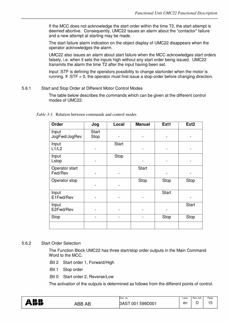
5.6.1 Start and Stop Order at Different Motor Control Modes
The table below describes the commands which can be given at the different control modes of UMC22.
Table 3-1. Relation between commands and control modes
Order Jog Local Manual Ext1 Ext2
Input JogFwd/JogRev
Start Stop
-
-
-
-
Input L1/L2
-
Start -
-
-
Input Lstop
-
Stop -
-
-
Operator start Fwd/Rev
-
-
Start -
-
Operator stop -
-
Stop Stop Stop
Input E1Fwd/Rev
-
-
-
Start -
Input E2Fwd/Rev
-
-
-
-
Start
Stop - - - Stop Stop
5.6.2 Start Order Selection
The Function Block UMC22 has three start/stop order outputs in the Main Command Word to the MCC.
:Bit 2 Start order 1, Forward/High
:Bit 1 Stop order
:Bit 0 Start order 2, Reverse/Low
The activation of the outputs is determined as follows from the different points of control.

Functional Unit UMC22 Functional Description
Doc. no. Lang. Rev. ind. Page
ABB AB 3AST 001 599D001 en D 16
5.6.2.1 Control mode JOG
FB input :JogFwd or :JogRev
5.6.2.2 Control mode LOCAL
FB input :L1 or :L2
5.6.2.3 Control mode MAN
The operator issues a Start order from OperateIT
Operator Station.
5.6.2.4 Control mode Ext1/Ext2
A superior control program sets the inputs :E1(2)Fwd or :E1(2)Rev to issue a new start order.
See the table below.
:E1(2)Fwd/Rev Stop Descr
0 0 No change.
1 0 No change.
1 1 Start order
5.6.2.5 Change of Direction/Speed
If a new start-order is issued, this is compared with the previous start-order. If they are different the new order is delayed with time equal to input :T4.
5.6.2.6 Control mode DISABLE
The motor cannot be started.
5.6.2.7 Control mode Panel Mode
Panel Mode is activated when the motor control is switched to Panel. The Operator Station will no longer hold any control. However operator still capable of stopping the motor or reset the alarm / fault. When the panel mode is released, the control mode will go to Manual.
5.7 Fault Evaluation in the Control Circuit
Evaluation is performed in the priority order M1, M2, M5,M3 and M4. This means that if the Input :M1 =0, the inputs from M2-M5 are not regarded etc. The signal ME interlocks the complete evaluation. ME=0 is used to prevent incorrect alarms with, for example, a total control voltage failure. The inputs M1 to M5 are to be TRUE when there are no errors. The evaluation presupposes that the control circuit consists of a number of breaking contacts in series. Alarm handling of M1 is blocked internally in the Function Block with the motor at standstill.
Functional Unit UMC22 Functional Description
Doc. no. Lang. Rev. ind. Page
ABB AB 3AST 001 599D001 en D 17
5.8 Supervision of Motor Current
The input 2 in the profibus interface has information for motor current. The current supervision is obtain directly from UMC.
5.9 Interaction Window
The interaction window is available in the ControlIT
Control Builder. The interaction window is an engineering aid used to simplify configuration and blocking of signals not available on the faceplates. Changes to values in the Interaction window are only available in ‘Online’ mode in Control IT.
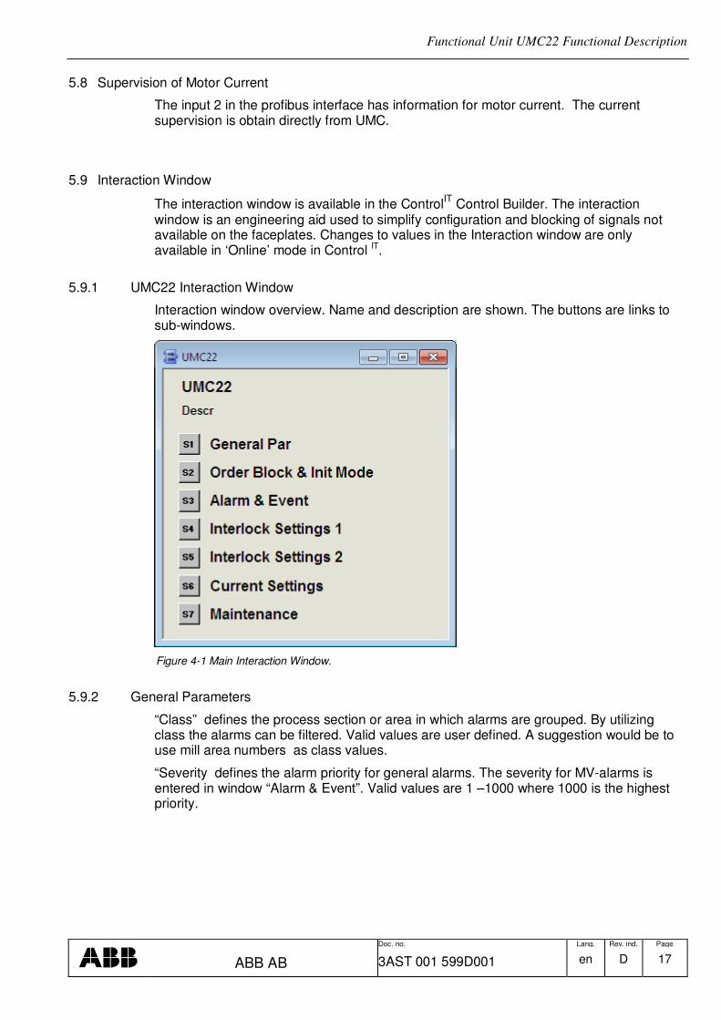
5.9.1 UMC22 Interaction Window
Interaction window overview. Name and description are shown. The buttons are links to sub-windows.
Figure 4-1 Main Interaction Window.
5.9.2 General Parameters
“Class” defines the process section or area in which alarms are grouped. By utilizing class the alarms can be filtered. Valid values are user defined. A suggestion would be to use mill area numbers as class values.
“Severity defines the alarm priority for general alarms. The severity for MV-alarms is entered in window “Alarm & Event”. Valid values are 1 –1000 where 1000 is the highest priority.

Functional Unit UMC22 Functional Description
Doc. no. Lang. Rev. ind. Page
ABB AB 3AST 001 599D001 en D 18
Figure 4-2 General Parameters.
5.9.3 Order Block
Blocking of operator order are entered in this window.
Figure 4-3 Order Block.
5.9.4 Alarm and Event Block
Alarm and Events are generated for status change on the signals defined in interaction window.
All Operator Events are reported by Audit Trail Functionality and not included in the FunctionBlock.
The individual text string for each event is stored in the Alarm and Event Translator aspect. This text can be NLS handled.
For Alarm Configuration the following values are valid
0 No Alarm or Event are generated
1 Alarm and Event are generated
2 Event is generated

Functional Unit UMC22 Functional Description
Doc. no. Lang. Rev. ind. Page
ABB AB 3AST 001 599D001 en D 19
Figure 4-4 Alarm & Event Block.
5.9.5 Interlock Settings
The different settings for interlocks are entered in this window.
Functional Unit UMC22 Functional Description
Doc. no. Lang. Rev. ind. Page
ABB AB 3AST 001 599D001 en D 20
Figure 4-5 Interlock Settings.
5.9.6 Current settings
Motor nominal (rated) current and normal current is entered in this window.
The actual current is also indicated.

Functional Unit UMC22 Functional Description
Doc. no. Lang. Rev. ind. Page
ABB AB 3AST 001 599D001 en D 21
Figure 4-6 Current settings.
5.9.7 Texts
The different interlock and information texts are entered in the aspect Text Properties. The length of the text is limited to about 60 characters, by the size of presentation element in the Interlock Display.
Figure 4-7 Texts.
5.9.8 Maintenance
This window has indication and control of start- and run time-counter.

Functional Unit UMC22 Functional Description
Doc. no. Lang. Rev. ind. Page
ABB AB 3AST 001 599D001 en D 22
Figure 4-8 Maintenance.

Functional Unit UMC22 Functional Description
Doc. no. Lang. Rev. ind. Page
ABB AB 3AST 001 599D001 en D 23
6 Operator Functions
The Operator functions are divided in principle into 4 parts:
• Presentation (Display elements, Time logged properties)
• Faceplate (Dialog)
• Alarm and Event handling
• Text handling
6.1 Presentation
6.1.1 Display elements
Display elements which can be used for different display types are available for use in the functional unit UMC22.
The display elements show the status and the controls of the process with different degrees of detail and are intended for the following displays:
• Object display
• Process display
• Diagnostic display
• Interlock display
Examples of different display elements which could be used in these displays are given in the following sections.

Functional Unit UMC22 Functional Description
Doc. no. Lang. Rev. ind. Page
ABB AB 3AST 001 599D001 en D 24
6.1.1.1 Object display
Figure 5-1 Object Display.
6.1.1.2 Process display
Figure 5-2 Process Display Element.

Functional Unit UMC22 Functional Description
Doc. no. Lang. Rev. ind. Page
ABB AB 3AST 001 599D001 en D 25
6.1.1.3 Diagnostic display
6.1.1.4 Diagnostic display Configuration
6.1.1.5 Interlock display
This display shows the actual status of all Interlock. The operator can override individual interlocks or all interlock.
Interlocks that can be overrided must be set to Blockable. This can be done from this display it the user has permission Configure or from the Interaction Window see chapter 5.9.5.

Functional Unit UMC22 Functional Description
Doc. no. Lang. Rev. ind. Page
ABB AB 3AST 001 599D001 en D 26
Start Interlock, Block Event and IA Blocked when no in E1 or E2 mode are parameters that can be set from this display if the user has Permission Configure or from Interaction Window.
6.1.2 Time-logged Properties
Measured values stored can be presented graphically in the form of curves on the display screen. Such a display, a Trend display, can consist of 1-4 curves. All properties for the object UMC22 are available to be logged on the trend curves.

Functional Unit UMC22 Functional Description
Doc. no. Lang. Rev. ind. Page
ABB AB 3AST 001 599D001 en D 27
Figure 5-3 Trend Curve
6.2 Faceplate (Dialog)
The display screen is supplemented with a mouse and keyboard for operator communication with the functional unit/object.
By using OperateIT
Operator Station the operator can view and control the process through faceplates. The dialogue consists of buttons, indicators and graphic presentations within a Faceplate. A faceplate has three levels of dialogue, which are presented by the following three runtime views:
• Reduced Faceplate, where the size and contents typically have been optimized to cover most of the normal process operator actions. Minimum dialogue.
• Faceplate, which typically covers all normal process operator actions. This view is disabled as default.
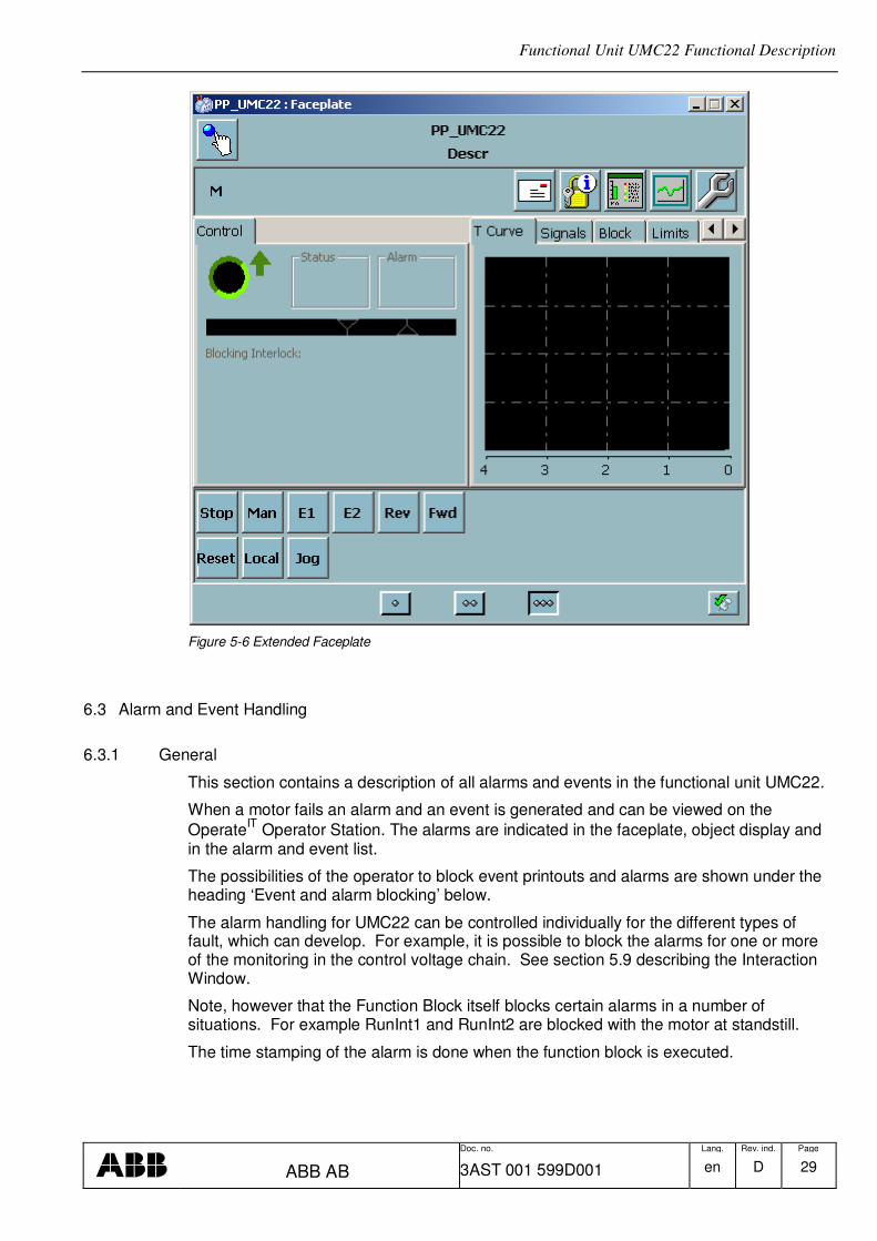
• Extended Faceplate, with functions and information intended for the process engineer or the advanced operator. Maximum dialogue.
The figures 5-3 to 5-12 below and overleaf illustrate the various presentations of the faceplate.

Functional Unit UMC22 Functional Description
Doc. no. Lang. Rev. ind. Page
ABB AB 3AST 001 599D001 en D 28
Figure 5-4 Reduced Faceplate Figure 5-5 Faceplate
Functional Unit UMC22 Functional Description
Doc. no. Lang. Rev. ind. Page
ABB AB 3AST 001 599D001 en D 29
Figure 5-6 Extended Faceplate
6.3 Alarm and Event Handling
6.3.1 General
This section contains a description of all alarms and events in the functional unit UMC22.
When a motor fails an alarm and an event is generated and can be viewed on the
OperateIT
Operator Station. The alarms are indicated in the faceplate, object display and in the alarm and event list.
The possibilities of the operator to block event printouts and alarms are shown under the heading ‘Event and alarm blocking’ below.
The alarm handling for UMC22 can be controlled individually for the different types of fault, which can develop. For example, it is possible to block the alarms for one or more of the monitoring in the control voltage chain. See section 5.9 describing the Interaction Window.
Note, however that the Function Block itself blocks certain alarms in a number of situations. For example RunInt1 and RunInt2 are blocked with the motor at standstill.
The time stamping of the alarm is done when the function block is executed.

Functional Unit UMC22 Functional Description
Doc. no. Lang. Rev. ind. Page
ABB AB 3AST 001 599D001 en D 30
Figure 5-7 Alarm List
6.3.2 Alarm and Event Message
The following alarm texts are generated by the functional unit UMC22 object The “Message Description” are “hard coded” in the function block and can not be modified.
The “Condition” text are stored in the Alarm and Event Translator aspect and can be NLS handled.
Object Name Object Description Condition Message Description
<Name> <Description> Communication Error
Fault
<Name> <Description> Control Voltage Fault
<Name> <Description> Overload Fault
<Name> <Description> Local Stop Fault
<Name> <Description> Safety Monitor Fault
<Name> <Description> Short Curcuit Fault
<Name> <Description> Main Contactor Fault
<Name> <Description> Fault Fault
<Name> <Description> Warning Fault
<Name> <Description> RunInt1 “Run1 Text” form Text Properties aspect
<Name> <Description> RunInt2 “Run1 Text” form Text Properties aspect
The following Event texts are generated by the functional unit UMC22.
The “Message Description” text are stored in the Alarm and Event Translator aspect and can be NLS handled.
SourceName ObjectDescription Condition Message Description
<Name> <Description> SeqE1 Mode
<Name> <Description> SeqE2 Mode

Functional Unit UMC22 Functional Description
Doc. no. Lang. Rev. ind. Page
ABB AB 3AST 001 599D001 en D 31
<Name> <Description> SeqMan Mode
<Name> <Description> Local Mode
<Name> <Description> Panel Mode
<Name> <Description> Remote Mode
<Name> <Description> Ext Start FWD
<Name> <Description> Ext Start REV
<Name> <Description> Ext Stop
<Name> <Description> IC1 On
<Name> <Description> IC1 Off
<Name> <Description> IC2 On
<Name> <Description> IC2 Off
<Name> <Description> IB1 On
<Name> <Description> IB1 Off
<Name> <Description> IB2 On
<Name> <Description> IB2 Off
<Name> <Description> IB3 On
<Name> <Description> IB3 Off
<Name> <Description> IB4 On
<Name> <Description> IB4 Off
<Name> <Description> IA1 On
<Name> <Description> IA1 Off
<Name> <Description> IA2 On
<Name> <Description> IA2 Off
<Name> <Description> Run On
<Name> <Description> Run Off
<Name> <Description> Alarm Acknowledge
<Name> <Description> Alarm Control Block
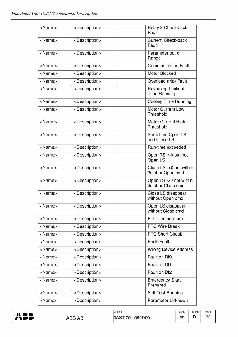
6.3.3 Diagnostic events
This event can not be blocked.
SourceName ObjectDescription Condition Message Description
<Name> <Description> Fault Input Signal
<Name> <Description> Self Test Failed
<Name> <Description> Relay 0 Check-back Fault
<Name> <Description> Relay 1 Check-back Fault
Functional Unit UMC22 Functional Description
Doc. no. Lang. Rev. ind. Page
ABB AB 3AST 001 599D001 en D 32
<Name> <Description> Relay 2 Check-back Fault
<Name> <Description> Current Check-back Fault
<Name> <Description> Parameter out of Range
<Name> <Description> Communication Fault
<Name> <Description> Motor Blocked
<Name> <Description> Overload (trip) Fault
<Name> <Description> Reversing Lockout Time Running
<Name> <Description> Cooling Time Running
<Name> <Description> Motor Current Low Threshold
<Name> <Description> Motor Current High Threshold
<Name> <Description> Sametime Open LS and Close LS
<Name> <Description> Run-time exceeded
<Name> <Description> Open TS ->0 but not Open LS
<Name> <Description> Close LS ->0 not within 3s after Open cmd
<Name> <Description> Open LS ->0 not within 3s after Close cmd
<Name> <Description> Close LS disappear without Open cmd
<Name> <Description> Open LS disappear without Close cmd
<Name> <Description> PTC Temperature
<Name> <Description> PTC Wire Break
<Name> <Description> PTC Short Circuit
<Name> <Description> Earth Fault
<Name> <Description> Wrong Device Address
<Name> <Description> Fault on DI0
<Name> <Description> Fault on DI1
<Name> <Description> Fault on DI2
<Name> <Description> Emergency Start Prepared
<Name> <Description> Self Test Running
<Name> <Description> Parameter Unknown

Functional Unit UMC22 Functional Description
Doc. no. Lang. Rev. ind. Page
ABB AB 3AST 001 599D001 en D 33
6.4 Faceplate tabs
6.4.1 Alarm and Event blocking
By using the faceplate it is possible for the process engineer to block alarms.
Figure 5-8 Extended Faceplate (Block) Figure 5-9 Extended Faceplate (Signals)
6.4.2 Limits
Figure 5-10 Extended Faceplate (Limits).

Functional Unit UMC22 Functional Description
Doc. no. Lang. Rev. ind. Page
ABB AB 3AST 001 599D001 en D 34
6.4.3 Info
Figure 5-11 Extended Faceplate (Info)
6.4.4 Maintenance
The reason for the last stop of the motor is presented in the faceplate. This text stays until the next time the motor stops.
Figure 5-12 Extended Faceplate (Maintenance)

Functional Unit UMC22 Functional Description
Doc. no. Lang. Rev. ind. Page
ABB AB 3AST 001 599D001 en D 35
7 Profibus Device Object type ABB UMC 22
The Function block UMC22 is based on the following data structures defined by the Device Type ABB UMC22 :
Inputs :
UMC_Input : 2 bytes
Structure or one direction
Structure for two direction
UMC_MotorCurrent :2 bytes
Output :
UMC_Output : 2bytes
Structure for one direction
Structure for two direction
7.1 Function Block UMC22_DI
This element is used to map data in the UMC_Input data structure output parameters.
The status of the UMC_Input data is stored as follow
Byte 1 Bit 2 is mapped to parameter DI_0 on the element
Byte 1 Bit 3 DI_1
Byte 1 Bit 4 DI_2

Functional Unit UMC22 Functional Description
Doc. no. Lang. Rev. ind. Page
ABB AB 3AST 001 599D001 en D 36
Byte 1 Bit 5 DI_3
Byte 1 Bit 6 DI_4
Byte 1 Bit 7 DI_5

Functional Unit UMC22 Functional Description
Doc. no. Lang. Rev. ind. Page
ABB AB 3AST 001 599D001 en D 37
REVISION
Rev. Page (P) Chapt. (C)
Description Date Dept./Init.
A First version 060914/EA B Updated for release 4.0/5 2007-08-07/BP C Rev 5.0-1 Interlock functionality updated 081213/BP D Update rev 5.1/0 101103/BP