Functional Decomposition of a Medium Voltage DC Integrated Power … · 2019-11-01 · Functional...
15
Functional Decomposition of a Medium Voltage DC Integrated Power System ASNE SYMPOSIUM 2008 SHIPBUILDING IN SUPPORT OF THE GLOBAL WAR ON TERRORISM April 14-17, 2008 Mississippi Coast Coliseum Convention Center Mississippi Coast Coliseum Convention Center CAPT Norbert Doerry CAPT Norbert Doerry Technical Director, Future Concepts and Surface Ship Design Naval Sea Systems Command Dr. John Amy Di t P S t Approved for Public Release CAPT Doerry - Dr. Amy Director, Power Systems BMT Syntek Technologies
Transcript of Functional Decomposition of a Medium Voltage DC Integrated Power … · 2019-11-01 · Functional...

Functional Decomposition of a Medium Voltage DC Integrated Power System
ASNE SYMPOSIUM 2008SHIPBUILDING IN SUPPORT OF THE GLOBAL WAR ON TERRORISM
April 14-17, 2008Mississippi Coast Coliseum Convention CenterMississippi Coast Coliseum Convention Center
CAPT Norbert DoerryCAPT Norbert DoerryTechnical Director, Future Concepts and Surface Ship Design
Naval Sea Systems Command
Dr. John AmyDi t P S t
April 2008 Approved for Public Release CAPT Doerry - Dr. Amy
1
Director, Power SystemsBMT Syntek Technologies
Agenda
• NGIPS Technology Development Roadmap• Notional MVDC Architecture• Functional Requirements
– Power Management – Normal Conditions– Power Management – Quality of Service– Power Management – Survivability– System Stability– Fault Response– Power Quality– Maintenance Support– System Grounding
• Conclusions
April 2008 Approved for Public Release CAPT Doerry - Dr. Amy
2

NGIPS Technology Development Roadmap
Vision: To produce affordable power solutions for future surface combatants, submarines, expeditionary warfare ships, combat logistic ships, maritime prepositioning force ships, and support vessels.ships, maritime prepositioning force ships, and support vessels.
The NGIPS enterprise approach will:• Improve the power density and affordability of p p y yNavy power systems• Deploy appropriate architectures, systems, and components as they are ready into ship acquisition programsq p g• Use common elements such as:
• Zonal Electrical Distribution Systems (ZEDS)• Power conversion modules• Electric power control modules
• Implement an Open Architecture Business and Technical Model• Acknowledge MVDC power generation with ZEDS as the Navy’s primary challenge for future
April 2008 Approved for Public Release CAPT Doerry - Dr. Amy
3
combatants
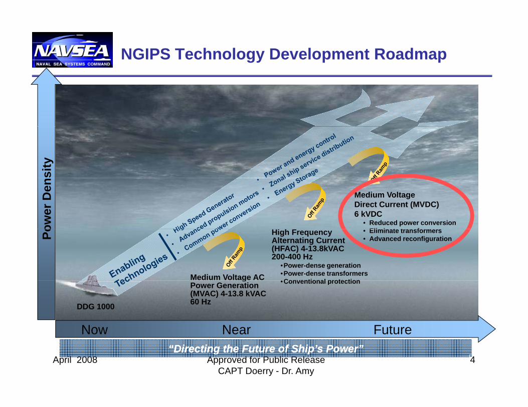
NGIPS Technology Development Roadmapsi
tyow
er D
en
Hi h F
Medium Voltage Direct Current (MVDC) 6 kVDC
• Reduced power conversionEli i t t fPo High Frequency
Alternating Current (HFAC) 4-13.8kVAC200-400 Hz
•Power-dense generation•Power-dense transformers•Conventional protectionMedium Voltage AC
• Eliminate transformers• Advanced reconfiguration
Now Near Future
DDG 1000
•Conventional protectiongPower Generation (MVAC) 4-13.8 kVAC60 Hz
April 2008 Approved for Public Release CAPT Doerry - Dr. Amy
4
Now Near Future“Directing the Future of Ship’s Power”“Directing the Future of Ship’s Power”

Notional MVDC Architecture
• Power Generation Modules produce Medium Voltage DCproduce Medium Voltage DC Power– Between 6 and 10 kV
• Large Loads (such as• Large Loads (such as Propulsion Motor Modules) interface directly to the MVDC busbus
• PCM-B is interface to in-zone distribution system
• Control provided by PCON• Control provided by PCON
Location of Energy Storage withinArchitecture still an open issue
April 2008 Approved for Public Release CAPT Doerry - Dr. Amy
5
Architecture still an open issue

Power System Functions
• Power Management –Normal Conditions
• Power Management –Quality of Service
• Power Management –Survivability
• System StabilitySystem Stability• Fault Response• Power Qualityy• Maintenance Support• System Grounding
April 2008 Approved for Public Release CAPT Doerry - Dr. Amy
6

Power Management – Normal Conditions
• Provide sufficient power to all loads while providing sufficient rolling reserve
• LOAD DEPENDENT POWER MANAGEMENT MODEL– Base rolling reserve on the
total amount of load and the Radan 2004
current operating condition• RESOURCE
MANAGEMENT MODEL
Mission Systems Resource Systems
Electric PlantTraining
Logistics Support
MobilityCombat Systems
Cargo Handling
– Calculate Rolling Reserve based on negotiations between Resource M
g ppFire Main
g gCommandand Control
April 2008 Approved for Public Release CAPT Doerry - Dr. Amy
7
Managers

Power Management – Quality of Service
• Provide Power Continuity to the degree needed by the loads
– Un-interruptiblep– Short term interruptible – Long term interruptible
• ROLLING RESERVE MODEL– Respond to a shortage in power generation
it b h ddi l t i t t
ENERGYPRODUCTION(GENERATION)
DISTRIBUTIONENERGY
USE(LOADS)
capacity by shedding long-term interrupt loads.
– Keep sufficient power generation capacity online to power uninterruptible and short-term interruptible loads on loss of the largest online generator
ENERGY EXCESSgenerator.
– Restore Long term interrupt loads are when sufficient power generation capacity is restored.
• ENERGY STORAGE MODELU t t i t tibl ENERGY
EXCESS
ENERGY DEFICIENCY
ENERGY– Use energy storage to power uninterruptible and short-term interruptible loads until sufficient power generation is restored to power all loads.
ENERGYSTORAGE
ENERGYDISPOSAL
April 2008 Approved for Public Release CAPT Doerry - Dr. Amy
8

Power Management – Survivability
• Zonal Survivability is assumed. Issues become
– Which power system components are safe to energize?
– Which loads are safe to energize?– What is the priority ranking of loads toWhat is the priority ranking of loads to
re-energize? • OPERATOR-BASED RESPONSE
MODEL– System reports the condition of power
system equipment and loads.– Operator makes decisions.
• AGENT BASED RESPONSE MODEL• AGENT BASED RESPONSE MODEL– Resource Managers (computer agents)
determine health of equipment and make decisions.
April 2008 Approved for Public Release CAPT Doerry - Dr. Amy
9

System Stability
• Stability of DC Power Systems complicated by negative incremental resistance of constant power loads.p
• LINEAR STABILITY METHODS– Generally based on Gain and Phase
margins.– Measure of Small Signal Stability only.
G(s) = SL easu e o S a S g a Stab ty o y
– Need to address all operating conditions to assess stability.
• NONLINEAR STABILITY METHODS– Accurately model the time-varying, non-Accurately model the time varying, non
linear power system including initial conditions, system parameters and inputs.
– Determine equilibrium points.– Determine perturbations about each
equilibriumequilibrium.– For each perturbation about each
equilibrium, determine the dynamic response of the system and whether it is acceptable
April 2008 Approved for Public Release CAPT Doerry - Dr. Amy
10
(Flower and Hodge 2005)

Fault Response
• Fault Response Actions– Identifies that a fault has occurred– Reconfigures the power system g p y– Protects equipment and cables
• CIRCUIT BREAKER MODEL– Fault currents coordinate the tripping of
breakers. – Affordability Concerns
• DC Breakers• Power electronics sized to provide
sufficient fault current POWER ELECTRONICS MODEL• POWER ELECTRONICS MODEL
– Sensors and controls detect and localize faults.
– Use QOS to enable taking bus down to isolate fault with zero current switchesisolate fault with zero-current switches.
• Provide un-interruptible loads with alternate power source.
– Requires an architecture and a design methodology.
April 2008 Approved for Public Release CAPT Doerry - Dr. Amy
11
gy
(Phillips 2006)

Power Quality
• MVDC bus has a limited diversity of sources and loads.
– Ideal voltage range and degree of geIdeal voltage range and degree of regulation is not obvious.
• TIGHT TOLERANCE MODEL– Voltages regulated within a
relatively narrow band to a set
Volta
relatively narrow band to a set nominal voltage.
– Simplifies interface design• LOOSE TOLERANCE MODEL
PCON t i l lt
time
– PCON sets nominal voltage over a wide range.
– Regulate voltage within a band around the nominal voltage.O ti i t ffi i Vo
ltage
– Optimize system efficiency.– Increase complexity of sources and
loads.– Increase cable size to enable
ti t th l lt li it
V
ti
April 2008 Approved for Public Release CAPT Doerry - Dr. Amy
12
operation at the lower voltage limit. time

Maintenance Support
• Electrically isolate equipment in a safe and verifiable manner to support Maintenance.
• PHYSICAL DISCONNECT MODEL– Isolate equipment with switches, circuit
breakers, removable links, removable fuses etcfuses, etc.
– Use of Danger Tags• CONTROL SYSTEM, POWER
ELECTRONICS DISCONNECT MODELMODEL
– Use power electronics to electrically isolate loads
• Isolate gate drive circuits?– Automate “Danger Tags” through
control system and component design.– Trades cost of hardware with
complexity and cost of control system.
April 2008 Approved for Public Release CAPT Doerry - Dr. Amy
13

System Grounding
• Should PCM-B provide galvanic isolation between the MVDC Bus (PDM-A) and the In-Zone Di t ib ti ?Distribution?
• PCM-B WITH GALVANIC ISOLATION
– Prevents DC Offsets from ground faults on MVDC bus fromfaults on MVDC bus from propagating into the In-Zone Distribution
– Weight of isolation transformers can be reduced by using high-frequency t f
Ground PlaneAC Waveform
transformers.• PCM-B WITHOUT GALVANIC
ISOLATION– Potentially lighter, smaller, and
cheapercheaper.– May require fast removal of ground
faults on the MVDC Bus to prevent insulation system failure in the In-Zone Distribution.
April 2008 Approved for Public Release CAPT Doerry - Dr. Amy
14

Summary
• NGIPS Technology Development Roadmap
• Notional MVDC Architecture• Functional Requirements
– Power Management –Normal Conditions
– Power Management –Quality of Service
– Power Management –Survivability
– System StabilityF lt R– Fault Response
– Power Quality– Maintenance Support
S t G di
April 2008 Approved for Public Release CAPT Doerry - Dr. Amy
15
– System Grounding