FULL SCALE TESTING OF PRECAST BEAM TO COLUMN...
155
FULL SCALE TESTING OF PRECAST BEAM TO COLUMN CONNECTION USING BILLET CONNECTOR AND BEAM HALF JOINT SUBJECTED TO REVERSIBLE LOADING WAN NORHASIAH WAN BIDIN DEPARTMENT OF CIVIL ENGINEERING UNIVERSITY OF MALAYA KUALA LUMPUR 2017
-
Upload
nguyenduong -
Category
Documents
-
view
223 -
download
0
Transcript of FULL SCALE TESTING OF PRECAST BEAM TO COLUMN...

FULL SCALE TESTING OF PRECAST BEAM TO COLUMN CONNECTION USING BILLET CONNECTOR
AND BEAM HALF JOINT SUBJECTED TO REVERSIBLE LOADING
WAN NORHASIAH WAN BIDIN
DEPARTMENT OF CIVIL ENGINEERING
UNIVERSITY OF MALAYA KUALA LUMPUR
2017

FULL SCALE TESTING OF PRECAST BEAM TO
COLUMN CONNECTION USING BILLET
CONNECTOR AND BEAM HALF JOINT SUBJECTED
TO REVERSIBLE LOADING
WAN NORHASIAH WAN BIDIN
DISSERTATION SUBMITTED IN FULFILMENT OF
THE REQUIREMENTS FOR THE DEGREE OF MASTER
OF ENGINEERING SCIENCE
DEPARTMENT OF CIVIL ENGINEERING
UNIVERSITY OF MALAYA
KUALA LUMPUR
2017

iii
UNIVERSITY OF MALAYA
ORIGINAL LITERARY WORK DECLARATION
Name of Candidate: WAN NORHASIAH BINTI WAN BIDIN
(I.C/Passport No:
Registration/Matric No: KGA080050
Name of Degree: Master of Engineering Science
Title of Project Paper/Research Report/Dissertation/Thesis (“this Work”):
FULL SCALE TESTING OF PRECAST BEAM TO COLUMN
CONNECTION USING BILLET CONNECTOR AND BEAM HALF JOINT
SUBJECTED TO REVERSIBLE LOADING
Field of Study:
I do solemnly and sincerely declare that:
(1) I am the sole author/writer of this Work;
(2) This Work is original;
(3) Any use of any work in which copyright exists was done by way of fair
dealing and for permitted purposes and any excerpt or extract from, or
reference to or reproduction of any copyright work has been disclosed
expressly and sufficiently and the title of the Work and its authorship have
been acknowledged in this Work;
(4) I do not have any actual knowledge nor do I ought reasonably to know that
the making of this work constitutes an infringement of any copyright work;
(5) I hereby assign all and every rights in the copyright to this Work to the
University of Malaya (“UM”), who henceforth shall be owner of the
copyright in this Work and that any reproduction or use in any form or by any
means whatsoever is prohibited without the written consent of UM having
been first had and obtained;
(6) I am fully aware that if in the course of making this Work I have infringed
any copyright whether intentionally or otherwise, I may be subject to legal
action or any other action as may be determined by UM.
Candidate’s Signature Date:
Subscribed and solemnly declared before,
Witness’s Signature Date:
Name:
Designation:

iv
ABSTRACT
Precast beam to column connection is an important element in precast concrete
structure, which has significantly influenced the overall structural performance. This
connection is used to transfer the shear, bending moment and sometimes torsion
between the precast components. This research is to determine the moment resistance
and moment rotation characteristic of new proposed precast beam to column connection
through three (3) full-scale experimental studies. The specimens used for the testing are
similar in geometrical and material properties. From the moment rotation characteristic,
it is possible to extract the rotational stiffness, moment capacity and ductility of the
connection. The experimental results were validated with existing analytical methods
and the connection classification is determined. It is found that the ultimate moment of
the connection, MU is greater than the calculated moment resistance, MRC for all
specimens with the average value of MU/MRC is 1.21. All the specimens failed beyond
the beam-line which means that the connection has sufficient ductility and achieved
required strength to be considered as a semi-rigid connection and might be considered
as a fully rigid. Based on the connection classification system according to Monforton’s
fixity factor, this connection falls in zone III, which is semirigid connection with
medium strength. The analytical model overestimates the experimental results due to the
omission of mechanical parts contribution such as the horizontal bolt, dowel and billet
in calculating the rotation. For failure mechanism, all specimens exhibit plastic hinge
formation in the beam at the column’s face which means that the ultimate moment
resistance of the beam was reached.

v
ABSTRAK
Sambungan rasuk-tiang merupakan elemen terpenting dalam struktur konkrit pra tuang
dimana kelakuannya mempengaruhi keseluruhan prestasi struktur bangunan konkrit pra
tuang. Sambungan ini berperanan untuk menghantar ricih, lenturan momen dan
kadangkala kilasan diantara komponen-komponen pra tuang. Kajian tesis ini adalah
untuk menentukan momen rintangan dan ciri-ciri momen putaran (moment rotation)
untuk sambungan konkrit pratuang yang dicadangkan melalui kaedah eksperimen
berskala penuh. Spesimen yang digunakan untuk ketiga-tiga ujikaji ini adalah sama dari
segi geometrik serta ciri-ciri bahan. Daripada ciri-ciri momen-putaran, kekakuan
putaran, kapasiti momen dan kemuluran sambungan dapat diestrak melalui eksperimen
ini. Disamping itu, keputusan eksperimen turut disahkan dengan kaedah analitikal dan
jenis sambungan dapat ditentukan. Hasil daripada ujikaji ini, didapati momen
maksimum, MU bagi sambungan pra-tuang ini lebih besar berbanding momen rintangan
teori (MRC) iaitu dengan nilai purata MU/MRC sebanyak 1.21. Semua spesimen semasa
gagal adalah melepasi garisan beam-line yang bermaksud sambungan tersebut
mempunyai kemuluran yang cukup untuk mecapai kekuatan yang dikehendaki untuk
dipertimbangkan sebagai sambungan separa tegar atau sambungan tegar. Berdasarkan
sistem klasifikasi Monforton’s fixity factor, sambungan pratuang ini berada dalam Zone
III iaitu sambungan separa tegar dengan kekuatan sederhana. Keputusan daripada
eksperimen adalah dibawah anggaran kaedah analitikal disebabkan oleh sumbangan
komponen mekanikal (bolt mendatar, dowel dan billet) tidak diambil kira dalam
pengiraan putaran. Bagi mekanisma kegagalan, semua specimen menunjukkan
kegagalan engsel plastik pada rasuk berhampiran muka tiang yang membawa maksud
momen rintangan maksimum bagi rasuk telah pun dicapai.

vi
ACKNOWLEDGEMENTS
First and foremost, I would like to address my sincere appreciation to my supervisor
Assoc. Prof. Dr. Nor Hafizah Ramli @ Sulong and Dr. Zainah Ibrahim for their
essential advice, necessary guidance and invaluable assistance in achieving the success
of this thesis. Without their encouragement, this thesis would not be possible.
My appreciation also goes to Dr. Kim S. Elliott, Ir. Kamaluddin Abd Rashid and
Ir Mohd Azhari Mohd Salleh for their generous guidance. Their guidance and detailed
explanation has helped me to understand many theories and concepts in designing a
precast connection. Thanks to Construction Research Institute of Malaysia (CREAM)
for financial and facilities support for this study.
Other than that, I would like to show my appreciation to my thesis partner
Rohani Mokhtar and CREAM’s Laboratory staff for their advice, help and assistance in
experimental work.
Lastly, my special thanks goes to my parent, Wan Bidin Hasan and Halimah
Mahmood, my husband, Azirul Hazimi Husain and my children, Hasya Sumayyah and
Harith Imtiyyaz for their continuous support and understanding during this period of
study. Thanks to Allah s.w.t for ease everything.
vii
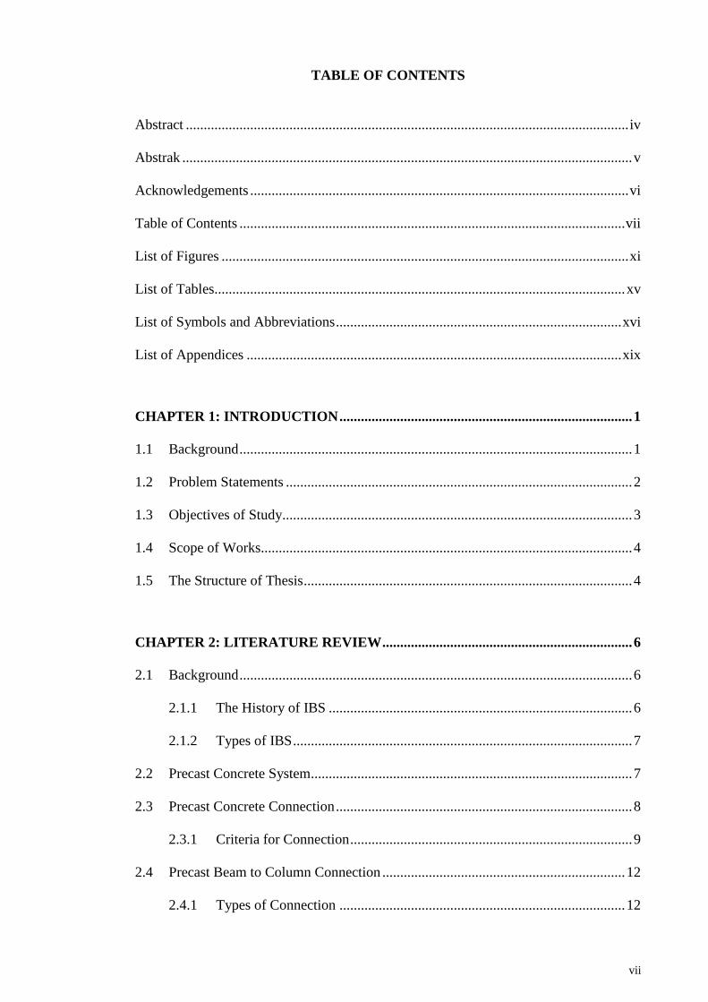
TABLE OF CONTENTS
Abstract ............................................................................................................................ iv
Abstrak .............................................................................................................................. v
Acknowledgements .......................................................................................................... vi
Table of Contents ............................................................................................................ vii
List of Figures .................................................................................................................. xi
List of Tables................................................................................................................... xv
List of Symbols and Abbreviations ................................................................................ xvi
List of Appendices ......................................................................................................... xix
CHAPTER 1: INTRODUCTION .................................................................................. 1
1.1 Background .............................................................................................................. 1
1.2 Problem Statements ................................................................................................. 2
1.3 Objectives of Study.................................................................................................. 3
1.4 Scope of Works........................................................................................................ 4
1.5 The Structure of Thesis ............................................................................................ 4
CHAPTER 2: LITERATURE REVIEW ...................................................................... 6
2.1 Background .............................................................................................................. 6
2.1.1 The History of IBS ..................................................................................... 6
2.1.2 Types of IBS ............................................................................................... 7
2.2 Precast Concrete System.......................................................................................... 7
2.3 Precast Concrete Connection ................................................................................... 8
2.3.1 Criteria for Connection ............................................................................... 9
2.4 Precast Beam to Column Connection .................................................................... 12
2.4.1 Types of Connection ................................................................................ 12

viii
2.4.2 Types of Precast Beam to Column Connection Used in Industry ............ 15
2.4.2.1 Precast Concrete Connection with Embedded Steel Members . 15
2.4.2.2 Precast Concrete Connection using Corbel ............................... 23
2.5 The Behaviour of the Connection .......................................................................... 24
2.5.1 Moment Rotation (M-) Relationship ...................................................... 24
2.5.2 Load Displacement Relationship .............................................................. 27
2.5.3 Beam Line Method ................................................................................... 28
2.5.4 Connection Classification ......................................................................... 31
2.5.5 Failure Modes and Crack Patterns ............................................................ 32
2.6 Analytical Model ................................................................................................... 35
CHAPTER 3: RESEARCH METHODOLOGY ....................................................... 40
3.1 Introduction............................................................................................................ 40
3.2 Design Stage .......................................................................................................... 42
3.2.1 Description of the Connection .................................................................. 42
3.3 Experimental Work ................................................................................................ 46
3.3.1 Fabrication at Site ..................................................................................... 46
3.3.2 Sub Assemblage of Specimen Components at Laboratory ...................... 47
3.3.3 Experimental Setup and Instrumentation ................................................. 52
3.3.4 Testing Procedure ..................................................................................... 57
3.4 Analytical Method ................................................................................................. 57
3.4.1 Moment-Rotation (M-) Calculation Technique ..................................... 57
3.4.1.1 Calculation of Moment .............................................................. 57
3.4.1.2 Calculation of Rotation ............................................................. 58
3.4.1.3 Calculation of Stiffness ............................................................. 60
3.4.2 Beam Line Method ................................................................................... 61

ix
3.4.3 Connection Classification ......................................................................... 62
CHAPTER 4: RESULTS AND DISCUSSIONS ........................................................ 63
4.1 Introduction............................................................................................................ 63
4.2 Material Testing ..................................................................................................... 63
4.2.1 Sika Grout 215 .......................................................................................... 63
4.2.2 Concrete .................................................................................................... 64
4.2.3 Tension Reinforcement (T16) .................................................................. 65
4.3 Results from Experiment ....................................................................................... 65
4.3.1 Moment Rotation (M-) Relationship ...................................................... 66
4.3.2 Load Displacement Relationship .............................................................. 69
4.3.3 Load Strain Curve .................................................................................... 71
4.3.4 Connection Classification ......................................................................... 76
4.3.5 Failure Modes and Crack Patterns ............................................................ 77
4.4 Analytical Result ................................................................................................... 81
4.5 Comparison of the Result ...................................................................................... 82
4.6 Discussion .............................................................................................................. 83
CHAPTER 5: CONCLUSIONS AND RECOMMENDATIONS ............................. 85
5.1 Conclusion ............................................................................................................. 85
5.2 Recommendation ................................................................................................... 86
References ....................................................................................................................... 87
List of Publications and Papers Presented ...................................................................... 90
Appendices ...................................................................................................................... 91
Appendix A : Design Calculation ................................................................................... 91
A1 : Beam Half Joint Design ................................................................................. 91
A2 : Steel Insert Design ......................................................................................... 98

x
A3 : Beam Design ................................................................................................ 103
Appendix B : Concrete Mix Design .............................................................................. 109
Appendix C : Beam Line Intersection Calculation ....................................................... 110
C1 : Calculation of End Moment of the Beam .................................................... 110
C2 : Calculation of Beam Line Gradient (m), Connection Stiffness (S), Stiffness
Factor (Ks) and Monforton Fixity Factor ().......................................... 113
Appendix D : Data for Moment Rotation Graph .......................................................... 116
D1 : Moment Rotation for BIC 1 ......................................................................... 116
D2 : Moment Rotation for BIC 2 ......................................................................... 119
D3 : Moment Rotation for BIC 3 ......................................................................... 121
Appendix E : Data for Load Displacement Graph ........................................................ 125
E1 : Load Displacement for BIC 1 (Cycle 3) ...................................................... 125
E2 : Load Displacement for BIC 2 (Cycle 3) ...................................................... 125
E3 : Load Displacement for BIC 3 (Cycle 3) ...................................................... 126
Appendix F : Data for Load Strain Graph ..................................................................... 127
F1 : Load Strain for BIC 1 ................................................................................... 127
F2 : Load Strain for BIC 2 ................................................................................... 130
F3 : Load Strain for BIC 3 ................................................................................... 132

xi
LIST OF FIGURES
Figure 2.1: Unsuccessful type of precast beam to column connection (Elliott,1996) .... 11
Figure 2.2: Unsuccessful type of precast beam to column connection (Elliott,1996) .... 12
Figure 2.3: Moment rotation curve for connections........................................................ 12
Figure 2.4: Effects of different connection types in terms of moment distribution
( Kooi, 2005) ................................................................................................................... 13
Figure 2.5: Illustration of different range of connection’s behavior ............................... 14
Figure 2.6: The application of embedded structural steel in precast beam to column
connection (Marcakis and Mitchell, 1980) ..................................................................... 15
Figure 2.7: Beam to column connection using halving joints and cast in steel insert
(Elliott, 1996) .................................................................................................................. 16
Figure 2.8 : Precast beam to column using solid billet with welded plate in beam
(Marcakis and Mitchell, 1980) ........................................................................................ 17
Figure 2.9: Precast beam to column connection using solid billet with welded plate in
beam (Elliott, 1996) ........................................................................................................ 18
Figure 2.10: Basic components of Cazaly Hanger (PCI,1988) ....................................... 18
Figure 2.11: Precast beam to column connection using solid or hollow billet with top
steel reinforcing bars (Elliott, 1996) ............................................................................... 19
Figure 2.12: Precast beam to column connection using solid or hollow billet section
with threaded dowel and top angle fixing (Elliott, 1996). .............................................. 20
Figure 2.13: Precast beam to column connection using open box and notched plate in
beam (Elliott, 1996) ........................................................................................................ 21
Figure 2.14: Precast beam to column connection using rolled H-section and bolted on
cleat (Elliott, 1996).......................................................................................................... 22
Figure 2.15: Precast concrete beam to column connection using rolled H-section and
bolted on cleat. ................................................................................................................ 23
Figure 2.16: Moment rotation curve ............................................................................... 25
Figure 2.17: The interpretation of stiffness in moment rotation curve ........................... 25
Figure 2.18: Typical moment-rotation curve (Park and Paulay, 1975)........................... 26

xii
Figure 2.19: Connection failing in compression (Park and Paulay, 1975) ..................... 26
Figure 2.20: Moment-rotation curve (Park and Paulay, 1975) ....................................... 27
Figure 2.21: Load displacement curve (Park and Paulay,1975) ..................................... 28
Figure 2.22: Moment-rotation characteristic of beam column connections (Elliott, 2002)
......................................................................................................................................... 29
Figure 2.23: Intersection of moment-rotation line with beam line (Elliott et al, 2003) . 30
Figure 2.24: Connection classification system for pinned, semi-rigid and fully rigid
beam to column connection. (Elliott & Jolly, 2013) ....................................................... 31
Figure 2.25: Possible failure modes within beam to column connection’s region
(Meinheit and Jirsa,1981)................................................................................................ 33
Figure 2.26: The failure modes obtained from experiment ( Hamil & Scott, 1999) ....... 35
Figure 2.27: Interface joint rotation due to joint opening (Elliott et al, 2003) ................ 37
Figure 2.28: Embedment length of reinforcement across columns (Elliott et al, 2004) . 38
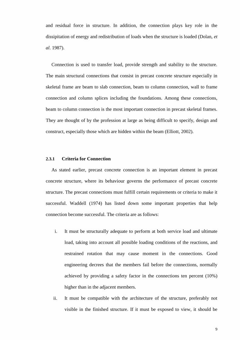
Figure 2.29: Plastic hinge length for types of precast connections (Elliott et al, 2004) . 39
Figure 3.1: The flowchart of the methods ....................................................................... 41
Figure 3.2: Existing precast beam to column connection (Fib, 2008) ............................ 42
Figure 3.3: The proposed precast beam to column connection ....................................... 43
Figure 3.4: Precast beam half joint detaling.................................................................... 44
Figure 3.5: Precast column detailing ............................................................................... 45
Figure 3.6: Tying the reinforcement ............................................................................... 47
Figure 3.7: Reinforcement inspection ............................................................................. 47
Figure 3.8: Reinforcement caging ready to be put in to the mould ................................. 47
Figure 3.9: Erection of connection .................................................................................. 48
Figure 3.10: Grouting process ......................................................................................... 49
Figure 3.11: Concrete mixing at laboratory .................................................................... 50
Figure 3.12: Slump test to determine the workability of concrete mixing ..................... 50

xiii
Figure 3.13: Concrete in moulds for cube test ................................................................ 51
Figure 3.14: Concreting at jointing part .......................................................................... 51
Figure 3.15: Painting process of the whole specimen ..................................................... 52
Figure 3.16: Experimental setup for flexural test............................................................ 53
Figure 3.17: Data logger that used to capture data from LVDT and strain gauge .......... 53
Figure 3.18 : Concrete strain gauge ................................................................................ 54
Figure 3.19: Steel strain gauge ........................................................................................ 54
Figure 3.20: Location of LVDT and concrete strain gauges ........................................... 55
Figure 3.21: Locations of steel strain gauges .................................................................. 56
Figure 3.22: Typical details for moment calculation method ......................................... 58
Figure 3.23 : Typical details for calculation of connection rotation ............................... 60
Figure 3.24: Internal force in the connection .................................................................. 61
Figure 3.25: The gradient, m of beam line (Elliott et al., 2003) ..................................... 62
Figure 4.1 : Internal lever arm, z for reinforcement bar and dowel ................................ 66
Figure 4.2: Moment-rotation (M-) graph for BIC 1 ...................................................... 66
Figure 4.3: Moment-rotation (M-) graph for BIC 2 ...................................................... 67
Figure 4.4: Moment-rotation (M-) graph for BIC 3 ...................................................... 67
Figure 4.5: M- graph with beam-line for all specimens of connection ......................... 68
Figure 4.6: Load displacement graph for BIC 1 ............................................................. 69
Figure 4.7: Load displacement graph for BIC 2 ............................................................. 70
Figure 4.8: Load displacement graph for BIC 3 ............................................................. 70
Figure 4.9: Load strain graph for BIC 1 .......................................................................... 72
Figure 4.10: Load strain graph for BIC 2 ........................................................................ 72
Figure 4.11: Load strain graph for BIC 3 ........................................................................ 73

xiv
Figure 4.12: Stiffness losses of BIC 1 ............................................................................. 75
Figure 4.13: Stiffness losses of BIC 2 ............................................................................. 75
Figure 4.14: Stiffness losses of BIC 3 ............................................................................. 76
Figure 4.15: First crack for all connections happened at column ................................... 78
Figure 4.16: Damage specimens ..................................................................................... 79
Figure 4.17: Cracks occurred at column region .............................................................. 79
Figure 4.18: Bar fractured failure for BIC 1 and BIC 2 .................................................. 80
Figure 4.19: Bar slipped failure at the BIC 3 connection ............................................... 81
Figure 4.20: Bar slipped from the splice connector ........................................................ 81
Figure 4.21 Experimental and predicted stiffness for BIC connection ........................... 83
Figure 4.22: LVDT 7 toppled during testing .................................................................. 84

xv
LIST OF TABLES
Table 2.1: Types of IBS and its applications .................................................................... 7
Table 2.2: Characteristic of connections ......................................................................... 13
Table 2.3: Ductility factor for building structure ............................................................ 28
Table 3.1: Pourable grout mixing proportion .................................................................. 49
Table 4.1: Grout strength for the specimens ................................................................... 64
Table 4.2: Concrete strength infill for the specimens ..................................................... 64
Table 4.3: Tensile test results for tension reinforcement ................................................ 65
Table 4.4: Summary of results obtained from experiments ............................................ 65
Table 4.5: Results obtained from M- graph .................................................................. 68
Table 4.6: Summary of results from load displacement graph ....................................... 71
Table 4.7: Summary of results from load strain graph.................................................... 73
Table 4.8: Monforton’s Fixity Factor value for BIC ...................................................... 76
Table 4.9: Predicted moment resistance, rotation, stiffness of the connection,
interception point and fixity factor for BIC connection ................................................ 82
Table 4.10: Comparison between experimental result and analytical prediction ........... 82

xvi
LIST OF SYMBOLS AND ABBREVIATIONS
Symbols
AS : Area of steel
d : Effective depth
fcu : Compressive strength of concrete
fy : Tensile strength of reinforcement
E : Young’s Modulus
Ec : Young’s Modulus of concrete
Es : Young’s Modulus of steel
I : Second moment of Area
kN : KiloNewton
KS : Stiffness factor
L : Beam span
m : Beam line gradient
m : Meter
mm : Millimeter
M : Moment
: Allowable moment capacity
MED : Allowable design moment capacity
ER : Required moment capacity
RC : Moment resistance of the connection
mm : Newton per millimeter square
P : Load
sw : Selfweight
S : Rotational stiffness

xvii
S : Secant stiffness
z : Lever arm
le : Embedment length of reinforcement across column
Lp : Plastic hinge length
: Monforton’s Fixity Factor
: Deflection
: Uniformly distributed load
: Rotation
C : End relative rotation
u : Displacement at ultimate load
y : Displacement at yield load
cr : Strain at cracking load
y : Strain at yield load
u : Strain at ultimate load

xviii
Abbreviations
BIC : Billet Connection
BS : British Standard
CIDB : Construction Industrial Development Board
CREAM : Construction Research Institute of Malaysia
IBS : Industrialised Building System
JKR : Public Work Department of Malaysia/ Jabatan Kerja Raya
KLIA : Kuala Lumpur International Airport
LVDT : Linear Variable Displacement Transducer
MS : Malaysian Standard
PKNS : Perbadanan Kemajuan Negeri Selangor
RHS : Rectangular Hollow Section
SHS : Square Hollow Section
UB : Universal Beam
UC : Universal Column
ULS : Ultimate Limit State

xix
LIST OF APPENDICES
Appendix A: Design Calculation…………………………………………………... 78
Appendix B: Concrete Mix Design………………………………………………... 96
Appendix C: Beam Line Intersection Calculation…...…………………………... 97
Appendix D: Data for Moment Rotation Graph 118
Appendix E: Data for Load Displacement Graph 126
Appendix F: Data for Load Strain Graph 128

1
CHAPTER 1: INTRODUCTION
1.1 Background
Beyond 2010, the government of Malaysia is moving towards adopting Industrialised
Building System (IBS) in our modern construction industry. IBS is defined as a
construction system in which components are manufactured in a factory, on or off site,
positioned and assembled into structure with minimal additional site work (CIDB,
2003).
IBS has been introduced to our construction industry since 1966, but the usage of
IBS is low and not so popular compared to cast in situ construction at that time. As a
result, IBS has been ignored until the Government of Malaysia reintroduced it again due
to its benefits. As the starting point, the Public Work Department of Malaysia (JKR) is
enforced to use the IBS at least seventy percent in their building design and encouraged
the engineers, architects and contractors from private sectors to use this new system.
The implementations of IBS are intended to reduce the unskilled workers, less
wastage, less volume of building materials, increased environmental and construction
site cleanliness and better quality control among others. Besides, it also promotes a safer
and more organised construction site, and reduces the completion time of construction.
As a result, the buildings like Petronas Twin Towers, Putrajaya, KL Sentral and Kuala
Lumpur International Airport (KLIA) have chosen this system instead of conventional
method.
To achieve the usage of IBS, the pre-cast concrete system is used. The pre-cast
concrete system employs the use of prefabricated components which are manufactured
using industrial process and assembled and erected into structures at sites. Pre-cast
building components have received a wide attention in the building construction and

2
have achieved a great deal of success in the modern day construction. Basically, there
are three (3) types of pre-cast concrete structure which are the wall frame, the portal
frame and skeletal frame. The skeletal frame mainly used for commercial offices, car
parks, shopping centers, schools and so on. While for portal frames, they are limited for
warehouses and wall frames are used for hotels, modular apartments etc.
The connection between pre-cast concrete components plays an important role in
determining the success of pre-cast concrete structures. The connection provides
connectivity among the precast element, it ensures the strength and rigidity of the
structure and its resistance to applied load. For a precast skeletal frame structure,
connection between the beam and column is very important, where the design and
analysis of precast skeletal structures is greatly influenced by this connection (Elliott et
al. 1998). This connection will govern the overall performance of the precast concrete
frame.
1.2 Problem Statements
Precast concrete structures with pinned connections are widely used throughout the
world. It provided simple in detailing and construction where the element to element
bearing is the simplest form of pinned connection. However, the structural depth for
precast connection is deep and it needs to be used together with bracing or shear wall
for lateral stability. The development of moment connection can minimize the structural
depth and reduce the use of bracing elements.
The most popular pinned connection used is corbel connection. Corbel is not
preferable by the architects due to its limitation in appearance. Thus, the architectural
demands have led to the design of invisible or hidden connection where the entire
connection is contained within the beam. The design of connection without corbel is an

3
approach to fulfill the architectural requirement. In addition, there is a need for a higher
capacity precast beam to column connection to meet moment connection requirement.
Currently, the experimental data for moment connection detail for precast beam to
column connection is still lacking. The data and the reliable behavior can only be
accessed by laboratory testing and proven performance. Thus, more experimental works
should be carried out to overcome these problems and also to obtain relevant data
especially for precast beam to column connection. This study carried out full scale
testing in order to develop a connection with similar behaviour of monolithic one.
1.3 Objectives of Study
This study was performed in order to achieve the following objectives:
i. To determine the moment resistance of proposed precast beam to column
connection through laboratory testing.
ii. To determine the connection classification of proposed precast beam to
column connection based on Connection Classification System according to
Monforton’s Fixity Factor.
iii. To validate the experimental results with analytical/ theoretical model result.
iv. To study the behaviour of precast beam to column connection in terms of
moment-rotation (M-) relationship, load displacement relationship, failure
modes and crack patterns.

4
1.4 Scope of Works
This study are focused on:
i. A new proposed precast beam to column connection using billet connector
together with beam half joint. This connection was designed based on
recommendation of BS8110:1997.
ii. Experimental works of proposed precast beam to column connection. A total
three (3) specimens with similar geometrical and material properties were
tested. The repetitive testing were carried out in order to confirm the results
and the average value of the tested parameters.
iii. Behaviour of proposed precast beam to column connection is obtained from
experimental works.
iv. Verification of analytical model of precast beam to column connection
chosen from study by Ferreira (1993).
1.5 The Structure of Thesis
Overall, this thesis consists of five (5) main chapters. The chapters are Introduction,
Literature review, Research methodology, Results and Discussions, Conclusions and
Recommendations.
The briefing of the topics, the objectives, scope of work, problem statements are
included in Chapter 1. In Chapter 2, the information regarding precast beam to column
connection, the previous research in this topic and types of connection are explained.
Chapter 3 presents the research methodology involved in order to achieve the
objectives.

5
The discussion about the results, analysis of results and errors occurred are described
in Chapter 4. Then, it followed with Chapter 5 which is the conclusions and
recommendations. All the whole research carried out in this study and its results are
concluded here. This chapter also consists of the recommendations and suggestions as
the guide for the next future researcher who have an interest to do research in this scope
of topics.

6
CHAPTER 2: LITERATURE REVIEW
2.1 Background
2.1.1 The History of IBS
The history of IBS began in early 1624 where panelised timber houses were shipped
from England to new settlement in North America. Then, the Crystal Palace in Hyde
Park, London was built in 1851 for Great Exhibition and Eiffel Tower in 1889 for Paris
World Expo and French Revolution Centenary. Whilst in Malaysia, the IBS concept
was introduced in 1966 where two pilot projects on IBS were launched by the
Government of Malaysia. These two pilot projects are namely the Pekeliling Flats Kuala
Lumpur and the Rifle Range Road Flat in Penang. Both projects applied the precast
concrete elements to build these high rise low cost flats. Then, it followed by housing
projects under Perbadanan Kemajuan Negeri Selangor (PKNS), a state government
development agency in 1981 till 1993. PKNS acquired precast technology from Praton
Haus International based in Germany (CIDB, 2003).
To date, the usage of IBS as a method of construction is evolving after four (4)
decades (1960-2000) in lukewarm situation. Many private companies team up with
foreign experts to offer IBS solutions. Local IBS players were also mushrooming. Many
private projects started to use IBS which previously dominant by government projects.
Current construction industry looking for better method of construction that offers
quality, safety, time and cost reduction, and also aesthetic value to the building
constructed. In extension of this, Malaysian construction industry is now moving
towards modernization, mechanization and industrialization of precast concrete
technology.

7
2.1.2 Types of IBS
Basically, there are many types of IBS and these can be categorized based on its
construction’s types. In Malaysia, Construction Industry Development Board (CIDB)
has classified IBS into five (5) major categories which are:
i. Precast concrete framing, panel and box systems
ii. Steel formwork systems
iii. Steel framing systems
iv. Prefabricated timber framing systems
v. Blockwork systems
The application of these types of IBS in construction industries are shown in Table
2.1 below.
Table 2.1: Types of IBS and its applications
Types of IBS Application
Precast concrete framing, panel
and box systems
Precast columns, beams, slabs, walls, 3D
components (staircases, toilets, balconies, lift
chambers, refuse chambers), and lightweight precast
concrete as well as permanent concrete formworks.
Steel formwork systems Tunnel formworks, beams and columns moulding
forms, tilt up systems, slab moulding forms and
permanent steel formworks (metal decks).
Steel framing systems Steel beam, columns, portal frames, roof trusses
Prefabricated timber framing
systems
Timber frame, timber roof trusses
Blockwork systems Interlocking concrete masonry unit (CMU),
lightweight concrete blocks
2.2 Precast Concrete System
To achieve the usage of IBS, the precast concrete system is used. The precast
concrete system employs the use of prefabricated components which are manufactured
using industrial process and assembled and erected into structures at sites. Precast

8
building components have received a wide attention in the building construction and
have achieved a great deal of success in the modern day construction.
Basically, there are three (3) types of precast concrete structure which are wall frame,
portal frame and skeletal frame. The skeletal frames are mainly used for commercial
offices, car parks, shopping center, schools and so on, While for portal and wall frames,
they are limited for warehouses, industrial buildings, hotels, modular apartments etc.
The application of precast concrete systems has introduced many advantages in
construction industries. The advantages are the reduction of the construction period,
good quality, low sensitivity to weather conditions, reduction of manpower on site and
the possibilities to achieve greater span through the use of pre- tensioning method (FIP
Commission on Prefabrication, 1986). However, to remain competitive, precast must be
simple and fast in erection. Thus, the development of an efficient connection is very
important.
2.3 Precast Concrete Connection
Precast concrete construction requires the presence of connection for assembling
phase and to give the construction monolithic quality required for strength and
durability. The connection design and realization have always presented the main
difficulties in precast concrete construction (Song, 2004).
According to Trikha, et al. (2004), connection can be defined as the component that
provides connectivity amongst more than two precast elements assuring rigidity of the
structure and its resistance to the applied loads. The connection between precast
concrete components plays an important role in determining the successful of precast
structures where its behaviour affects the constructability, stability, strength, flexibility
9
and residual force in structure. In addition, the connection plays key role in the
dissipitation of energy and redistribution of loads when the structure is loaded (Dolan, et
al. 1987).
Connection is used to transfer load, provide strength and stability to the structure.
The main structural connections that consist in precast concrete structure especially in
skeletal frame are beam to slab connection, beam to column connection, wall to frame
connection and column splices including the foundations. Among these connections,
beam to column connection is the most important connection in precast skeletal frames.
They are thought of by the profession at large as being difficult to specify, design and
construct, especially those which are hidden within the beam (Elliott, 2002).
2.3.1 Criteria for Connection
As stated earlier, precast concrete connection is an important element in precast
concrete structure, where its behaviour governs the performance of precast concrete
structure. The precast connections must fulfill certain requirements or criteria to make it
successful. Waddell (1974) has listed down some important properties that help
connection become successful. The criteria are as follows:
i. It must be structurally adequate to perform at both service load and ultimate
load, taking into account all possible loading conditions of the reactions, and
restrained rotation that may cause moment in the connections. Good
engineering decrees that the members fail before the connections, normally
achieved by providing a safety factor in the connections ten percent (10%)
higher than in the adjacent members.
ii. It must be compatible with the architecture of the structure, preferably not
visible in the finished structure. If it must be exposed to view, it should be

10
neat and unobtrusive, non-rusting, and non-staining, and watertight. Edges and
corners should be chambered and beveled.
iii. It must accommodate both manufacturing tolerances and erection tolerances.
Both of these tolerances must be considered when determining the sizes of
holes, sleeves, dowels, corbel and bearings, as well as erection clearances.
iv. It should be designed so that temporary bracing or connections can be made to
hold the precast unit in place so the crane can be released as soon as possible.
Tying up the expensive crane and crew for the extended time while the
connection is welded, bolted otherwise completed is a needless expense.
v. It should be the most economical connection possible that fulfils the
requirements of i, ii, iii and iv by considering all factors of precasting,
handling, and erecting. This implies the use of standard manufactured items
readily available in the market rather than specially made.
Besides, Elliott (1996) also listed down the criteria to satisfactory joint design. The
criterias are:
i. Components able to resist ultimate design loads in a ductile manner
ii. Components may be manufactured economically and be erected safely and
rapidly
iii. Tolerances for manufacturing and site erection do not adversely affect
intended structural behaviour, or are catered for in a ‘worst case’ situation.
iv. Final appearance of joint must satisfy the visual, fire and environmental
requirements
In addition, Vambersky (1990) has summarised the main criteria for the
serviceability performance of join in terms of:

11
i. strength
ii. influence of volume changes
iii. ductility
iv. durability, including corrosion and fire protection
v. simplicity in fabrication and erection
vi. temporary loading conditions
vii. economy and appearance
Figure 2.1 and Figure 2.2 show the connections that have been proven unsuccessful.
For Figure 2.1, the connection is unsuccessful due to no temporary bracing and difficult
to construct at site while connection in Figure 2.2 fails due to high cost and difficult to
position on site.
Figure 2.1: Unsuccessful type of precast beam to column connection (Elliott,1996)

12
Figure 2.2: Unsuccessful type of precast beam to column connection (Elliott,1996)
2.4 Precast Beam to Column Connection
2.4.1 Types of Connection
In precast concrete structural framed system, the precast beam to column connections
can be categorized into three (3) categories which are simple (pinned), semi-rigid and
rigid (fixed) connections. These three (3) categories indicate the degree of moment to be
transferred among the members. These behaviours are interpreted in typical moment
rotation curve shown in Figure 2.3.
Figure 2.3: Moment rotation curve for connections
Rigid
Semirigid
Ideal Pinned
Ideal Rigid

13
The rigid connection transferred full moment between members while simple
connection transferred zero moment. The degree of moment transfer for semi rigid
connection falls between rigid and simple connections. These connections are neither
ideally pinned nor ideally fixed. The differences effect of connection types in terms of
moment distribution in a structure is shown in Figure 2.4.
Figure 2.4: Effects of different connection types in terms of moment distribution
( Kooi, 2005)
The characteristic of this connection are described in Table 2.2 below:
Table 2.2: Characteristic of connections
Types of connection Characteristic
Simple connection
i. Simple connections (Figure 2.5b) are assumed to transfer
vertical shear only.
ii. Both rotational stiffness and moment resistance are small
and may be reasonably neglected (can be assumed to
approach zero value), leading to the concept of a pinned or
hinged connection.
iii. Such connection can be used only in non-sway frame where
the lateral loads are resisted by some alternative
arrangements such as bracing or shear wall.

14
iv. Typically used in braced frames where strength rather
stiffness govern the design.
v. This connection lends themselves to simple detailing and
construction, and maybe formed in the simplest manner by
element to element bearing (Elliott,1996).
Semi-rigid
connection
i. Semi-rigid (Figure 2.5c) connections are those fall between
simple and semi rigid connection.
ii. Such connections allow for a range of moment distribution
in frames. It is neither zero (or very small) as in pinned
connection nor fully moment transferred as in rigid
connection.
iii. It also does experience some degree of joint deformation
and this can be utilized to reduce the joint design moments.
iv. This connection has the true behaviour of the joint where
certain flexural deformation is allowed for nominal rigid
connection and certain degree of rotation is provided by
nominal pinned connections.
v. This type of connection may be used for both braced and
unbraced frames, but in the latter case the influence of the
connection flexibility on frame behaviour need to be
considered.
vi. They are also used in conjunction with other lateral load
resisting systems in order to increase the safety and the
performance of the overall structure.
Rigid Connection
i. Rigid connections (Figure 2.5a) are assumed to transfer full
moment to the column without undergo any rotation
between the members. Therefore, the moment rotation is
always assumed to be zero.
ii. Rigid connections are suitable for both braced and unbraced
frames. It provides stiffness requirement especially in high
rise and slender structure.
iii. This connection also contributes in resisting lateral loads
Figure 2.5: Illustration of different range of connection’s behavior
a. Rigid connection b. Pinned connection c. Semi-rigid connection

15
2.4.2 Types of Precast Beam to Column Connection Used in Industry
2.4.2.1 Precast Concrete Connection with Embedded Steel Members
Connections with embedded structural steel members serving as haunches or bracket
have been used for many years in precast concrete construction. The embedded steel or
steel insert is used to transfer shear and axial force, and sometimes bending and torsion
moment to the column (Elliott, 1996). Figure 2.6 shows the application of embedded
structural steel in precast beam to column connection.
Figure 2.6: The application of embedded structural steel in precast beam to column
connection (Marcakis and Mitchell, 1980)
Marcakis and Mitchell, (1980), have list down the advantages of this connection. The
advantages are:
i. The strength of this connection is not greatly depend on the strength of the
weld.
ii. Such connections do not usually require complicated reinforcement details.
iii. This connection can be easily designd to exhibit large ductility.

16
Normally, this embedded steel member will be used together with halving joint (half
beam joint) in precast beam to column connection. Figure 2.7 illustrates the beam to
column connection using halving joint and embedded steel member.
Figure 2.7: Beam to column connection using halving joints and cast in steel insert
(Elliott, 1996)
Generally, the embedded steel can be adopted from various sections such as:
i. Universal column or beam (UC or UB)
ii. Rolled channel, angle or bent plate
iii. Rolled rectangular or square hollow section (RHS, SHS, etc)
iv. Threaded dowel or bolts in steel or and plastic tubes
v. Bolt in cast-in steel sockets
Again, Marcakis and Mitchell, (1980) in their research have stated that different
sectional types of embedded structural steel member would affect the distribution of
load and stresses, stiffness of the connection and failure modes. For example, a
comparison results have been made between wide flange (UB or UC) and hollow
section (RHS, SHS, etc). The connection with wide flange is stiffer than connection

17
with hollow section. In terms of failure modes, vertical cracks are formed from both top
and bottom flange of the wide flange section. This indicates that both flanges are
effective in distributing the load. Compared to wide flange section, hollow steel section
has only one loading surface to distribute the load. Therefore, wide flange section is
more favorable in distributing the stresses in the connection.
Furthermore, if the hollow steel section had thin wall (not filled with concrete), the
bearing of the concrete against the top wall of the steel member could cause several
local bending. This affects the stresses concentrations in the concrete above the webs of
the hollow steel section and reduce the effective width of the connection. This leds to a
premature failure. Therefore, if the wall of a hollow steel section is not stiff enough, it
should be filled with concrete to ensure a more uniform bearing stress which will enable
the effective width to attain its maximum value.
In coherent with that, sometimes additional reinforcement is welded to the steel billet
whereas this reinforcement is assumed can act both in tension or compression (refer
Figure 2.8). The presence of welded reinforcement can increase the capacity and the
stiffness of the connection.This is proven by experiment and it also done by Marcakis
and Mitchell, (1980).
Figure 2.8 : Precast beam to column using solid billet with welded plate in beam
(Marcakis and Mitchell, 1980)

18
Besides that, there are several types of precast beam to column connection using
structural embedded steel members. Such connections are:
i. Precast beam to column connection using solid billet with welded plate in
beam (see Figure 2.9). This type of connection is a modified of Cazaly Hanger
(PCI, 1988) where the cantilever beam is replaced by a deep narrow plate and
the steel strap by two number of hooked end reinforcing bars welded to either
side of the plate (see Figure 2.10).
Figure 2.9: Precast beam to column connection using solid billet with welded plate
in beam (Elliott, 1996)
Figure 2.10: Basic components of Cazaly Hanger (PCI,1988)

19
The mechanisms of this connection are:
a. The projecting bars are arranged within the column width for temporary
means. But, if these projecting bars are fully anchored to the column or
continuous through the column, it is assumed that the projecting bars are fully
stressed at limit state.
b. The beam is fully anchored such that the billet is also fully effective.
c. The contribution of the solid steel billet is then ignored due to limited strength
of concrete infill at the bottom of the beam.
This simple connection can be designed to carry shear up to 500 kN. The
connection requires site welding but the fixing is rapid.
ii. Precast beam to column connection using solid or hollow billet with top steel
reinforcing bars (see Figure 2.11).
Figure 2.11: Precast beam to column connection using solid or hollow billet with top
steel reinforcing bars (Elliott, 1996)

20
According to Elliott, et al. (1998), the billet connector is based on conventional steel
haunch but without reinforcing bars welded to the sides of the box section. The
connectivity among precast beam and column insert comes from direct frictional
bearing with no positive mechanical action introduce between these both precast
components. This connection is attempted to generate sagging moment where it is
resisted by the addition of tie steel, bolted and/or welded plates. In addition, these
addition of tie steel, bolted and/or welded plates also provide torsional stability to the
connection.
iii. Precast beam to column connection using hollow section with threaded dowel
and top angle steel
Figure 2.12: Precast beam to column connection using solid or hollow billet section
with threaded dowel and top angle fixing (Elliott, 1996).
A threaded dowel is site fixed through a hole in the beam, supporting steel billet and
secured to a steel angle (or similar) at the top of the beam. This illustration is shown in
Figure 2.12. By doing this (top angle fixing), it would give immediate temporary

21
stability effect to the connection and a positive mechanical tie between the precast
components.
iv. Precast beam to column connection using open box and notched plate in beam
Figure 2.13: Precast beam to column connection using open box and notched plate in
beam (Elliott, 1996)
This type of connection is a hidden beam end connection for gravity loads that
eliminates the need for projecting column corbels. It provides a simple, efficient
connection that allows designer a new freedom in creating clean, elegant lines in the
completed precast concrete structure, fast in erection and it can function within normal
building. The application of this type of connection are very wide, it can be used in all
types of buildings where beam frames into the column. Such types of building are office
buildings, schools, hotels, car parks and any other similar structures.
However, even though this type of connection provides many benefits to the building
structure, but there is still a barrier to adapt to this system. The biggest barrier is the
designer itself where not all the designers are widely familiar with this system.

22
From the illustration in Figure 2.13, a steel box cast into the precast concrete beam
end while a sliding “knife” plate with a safety notch is cantilevered into a steel box is
also been cast into the concrete column.
v. Precast beam to column connection using rolled H-section and bolted on cleat
Figure 2.14: Precast beam to column connection using rolled H-section and bolted on
cleat (Elliott, 1996)
For this connection, the connectors (cleat) introduce a third part linking beam and
column units to avoid having mould penetration. Figure 2.14 shows how the column
and the cleat connector may be cast in a mould (Elliott, 2002). Basically, the strength of
this connection is greatly depends on a separate intermediate cleat. According to Elliott
(1996), typically this cleat are rolled angle or fabricated rod gusseted for strength. To
perform the connection, the cleat will receive a bolted connection to both beam and
column components. Top fixing maybe excluded due to the stability provided by the
bolt (at least two) group. This connection is expensive but safe to use. See also Figure
2.15.

23
Figure 2.15: Precast concrete beam to column connection using rolled H-section and
bolted on cleat.
2.4.2.2 Precast Concrete Connection using Corbel
Corbel is defined as short cantilever projection from the face of a column or a wall
which support a load bearing components on its upper horizontal ledge. Column corbel
is widely used in the Continental Europe and North America but not in United
Kingdom. This type of connection is not preferable by the architects due to its
appearance. Thus, the architectural demands have led to the design of invisible or
hidden connection whereas the entire connection is contained within the beam.
Basically, connections by using corbel are pinned joint and it only transfer shear
force to the column. If the corbel connection is applied to the frame structure, the frame
needs to use the bracing, core or shear wall in order to maintain the frame stability. This
is because the stability of the frame structure cannot be provided by the connection itself
due to it negligible stiffness. These lead to uneconomical design of column and
foundations.

24
However, it is possible to make this connection become semi rigid or rigid
connection. Such ways are to have steel protruding from the precast elements, welding
or overlapping the steel bars and achieving a moment resisting connection through in
situ concreting the joints and leave threaded sockets in precast elements to receive nuts
and bolts at site. Besides, it also be made by embedding steel sections or plates in the
precast elements using steel angles and plates
According to Elliott, et al. (1998), since 1990, the tests on corbel are not widely
carried out, the most testing are on welded plate and billet connector where some 24
tests have been carried out using those items within the period of time. Since the testing
on corbel is not widely carried out, Ab Rahman, et al. (2006) had carried out some
series of experiments by using corbel connections. Modifications and improvements
have been made to the original corbel to make it semi rigid or rigid connection. As a
result, these connections proved that the performance of connection in terms of
stiffness, strength and moment resistance is slightly higher than conventional
connection which is cast in situ and this connection also can cater moment compared to
the existing corbel.
2.5 The Behaviour of the Connection
2.5.1 Moment Rotation (M-) Relationship
The moment rotation (M-curve can interpret the behaviour of a connection
whether it is rigid, semi rigid or pinned connection. This classification is due to the
degree of moment to be transferred among the members. For example, the rigid
connection transferred full moment between members while simple connection
transferred zero moment. The level of transferred moment for semi rigid connection
falls between rigid and simple connection. This is shown in Figure 2.16.

25
Figure 2.16: Moment rotation curve
The moment rotation curve also represented the stiffness of the connection (see
Figure 2.17). The rotational stiffness for rigid connection is high while the pinned
connection has small stiffness.
Figure 2.17: The interpretation of stiffness in moment rotation curve
For beam to column connection testing, moment can be obtained by multiplying the
corresponding applied load with the distance of point load from the surface of the
column (Elliott, et al. 2003). The applied load is an incremental load. The rotation of the
connection can be obtained by dividing the corresponding vertical displacement with
the distance of the Linear Variable Displacement Transducer (LVDT) or dial gauge
from the surface of the column. The vertical displacement is usually measured using
LVDT as the rotation is assumed to be very small (Leong, 2006). The moment and
Design
strength
M
Stiffness
Deformation capacity

26
rotation for every incremental load is then plotted into a graph to produce the moment
rotation curve. According to Ling (2004), the same procedures are also used to obtain
the moment rotation curve for all numerical models with different values of distance of
point load and dial gauge. Figure 2.18 shows the typical moment-rotation curve.
Ductility of beam to column connection is crucial in precast concrete construction.
Therefore, crushing failure of concrete or brittle behaviour in connection must be
avoided. This is shown in Figure2.19. The ductility of connection can be determined
based upon factor of u/y, as shown in Figure 2.20.
Figure 2.18: Typical moment-rotation curve (Park and Paulay, 1975)
Figure 2.19: Connection failing in compression (Park and Paulay, 1975)

27
Figure 2.20: Moment-rotation curve (Park and Paulay, 1975)
2.5.2 Load Displacement Relationship
In precast concrete connection, the load displacement relationship is important to
determine the characteristic of the connection. The load displacement curve can
interpret whether the connections are ductile or brittle. A ductile connection is very
important especially if the structure subject to seismic loading or the structure being
loaded to failure in extreme event. This is because it is capable of undergoing large
deflection at near maximum load carrying capacity to give warning of failure and
prevent total collapse. Park and Paulay (1975) stated that this is due to the present
seismic design philosophy relies on energy absorption and dissipation by post-elastic
deformation for major survival in earthquakes. It is important to ensure that brittle
failure will not occur. The graph of load displacement is shown in Figure 2.21
Ductile behaviour can be expressed by the ratio of the ultimate deflection (ductility
factor), ∆u, to the deflection at initial yield, ∆y, or summarized as ∆u/∆y (Loo & Yao,
1995). According to Park (1988), the ductility factor may vary from 1 (full elastic) to 7
(ductile). Typically, the value for ductility factor is in the range 3 to 6. Department of
Public Works (2002), had categorized ductility factor as shown in Table 2.3.

28
Table 2.3: Ductility factor for building structure
Performance level of
building structure
Ductility factor
Full elastic
1
1.5
2
2.5
Partial ductile
3
3.5
4
4.5
Full ductile 5.3
Figure 2.21: Load displacement curve (Park and Paulay,1975)
2.5.3 Beam Line Method
According to Elliott, et al. (2003), in order to determine the rigidity of the
connection, a beam-line method can be used. This beam-line method represents the
characteristic of Mbehaviour of an elastic beam under a certain conditions of loading
in a flexural cracked state (Figure 2.22). In order to determine the beam-line for a
particular single beam subjected to uniformly distributed load (w) on a beam span (L),
moment rotation diagram is constructed by considering the extreme condition. The
conditions are:
Ductile behaviour
Brittle behaviour
Load
Deflection

29
i. First condition (to determine point A)
Pinned beam is assumed at point A which represent the rotation of the beam
at the support under distributed load (when M=0, = wL3/24EI).
ii. Second condition (to determine point B)
Fully rigid beam is assumed at point B which represent the hogging moment
of the beam at the support under distributed load (when =0 , M = wL2/12).
Figure 2.22: Moment-rotation characteristic of beam column connections (Elliott,
2002)
The line that connects Point A and Point is called “beam-line”. In order to assess any
connection, the moment-rotation plot needs to be verified against the beam-line. Thus,
the detail descriptions of beam line are as below:
Line 1 : represents the behaviour of a perfectly fully rigid connection
Line 2 : represents the behaviour of an ideally pinned connection

30
Line 3 : If a moment-rotation curve (Line 3) fails to across the beam-line AB,
the connection is considered as pinned due to the lack of the exhibited
ductility
Line 4 : If a moment-rotation curve (Line 4) crosses the beam-line, the
connection will have sufficient ductility and achieved required strength
to be considered as a semi-rigid connection, and might be considered as
a fully rigid connection.
Besides that, moment rotation curve incorporated with the beam-line is also used to
determine the allowable moment capacity of a connection (ME) and secant stiffness (SE)
(see Figure 2.23). The points along the beam-line define the relationship between the
end moment and end rotation of the beam. ME is defined from the intersection point of
beam-line and moment rotation line. SE also can be measured from this intersection.
Figure 2.23: Intersection of moment-rotation line with beam line (Elliott et al, 2003)
Then, the value of stiffness factor, KS also can be determined using calculation. The
equations for SE and KS are given by equations (1) and (2).
SE = ME
C
(1)

31
KS =SE
(4EI
L )⁄ (2)
2.5.4 Connection Classification
Connection classification is a classification system for pinned, semi-rigid and full
rigid beam-column connections. This system is proposed after Ferreira et al. (2005) and
this classification consist five distinct zones, shown in Figure 2.24.
Figure 2.24: Connection classification system for pinned, semi-rigid and fully rigid
beam to column connection. (Elliott & Jolly, 2013)
The descriptions of classification zones are as below:
Zone I : ≤ Pinned-connections
Zone II : ≤ Semi-rigid with low strength
Zone III : ≤ Semi-rigid with medium strength
Zone IV : ≤ Semi-rigid with high strength

32
Zone V : Rigid Connection
In order to use the system, the value of Monforton’s Fixity Factor ( must be
determined first. The Monforton’s Fixity Factor is given by the equation below:
= (1 +3EI
SEL)
−1
(3)
2.5.5 Failure Modes and Crack Patterns
Extensive research on beam to column connection has been carried out all over the
world. These researches are undertaken to investigate the behaviour of connection under
static loading and simulated seismic loading. According to Meinheit and Jirsa (1981),
the first experiment tests on beam-column connections were carried out in United States
by the Portland Cement Association in the early 1960’s and the results were published
seven (7) years later by Hanson and Corner (1967). From the experimentala test results,
Hanson and Corner (1967) have concluded that when the shear strength of the beam to
column connection is computed using equations developed for reinforced concrete
beams, a satisfactory estimate of the response of the beam-column connection under
repeated load could be obtained .
Then, Meinheit and Jirsa (1981) also stress out about five possible failure modes that
might occurred within the beam to column connection region. The possible mode of
failure is shown in Figure 2.25.

33
Figure 2.25: Possible failure modes within beam to column connection’s region
(Meinheit and Jirsa,1981)
The descriptions of the modes of failure are as below:
i. Beam hinging (Figure 2.25 (a)). This is the most desirable failure modes
among others and it is a ductile flexural failure of the beam at the connection.
Formation of hinges in the beams outside the connection allows for absorption
of energy through large inelastic deformation without lost of strength. The
mechanism is the same as beam hinging.
ii. Column hinging (Figure 2.25 (b)). Column hinging failure is less desirable
than beam hinging. The frame may have a residual sway deflection and may
be difficult to repair when the column hinged occurred.
iii. Column crushing (Figure 2.25 (c)). This type of failure is undesirable since it
affect the compressive load capacity of the column. The column compressive
load capacity may be reduced under this condition especially in tied columns.

34
iv. Reinforcing bar anchorage (Figure 2.25 (d)). It is undesirable failure modes if
the loss of anchorage of the reinforcement happened in exterior connections.
This is because lateral shear can no longer be transmitted by the frame. This
type of failure also causes a reduction in the energy absorbing ability of the
structural system.
v. Connections shear (Figure2.25 (e)). The consequences of failure of the
connection in shear are the same as loss of anchorage, an inability of the frame
to transfer lateral shear and declining energy absorbing ability.
In 1999, Hamil and Scott also have done research on beam to column connection.
From that research, three types of failure modes within beam to column connection zone
were obtained. The failure modes are shown in Figure 2.26. Again, according to Hamil
and Scott (1999), all specimens exhibited flexural cracking in the beam and the column
regions followed by diagonal cracking in the connection itself, as shown in Figure
2.26(a). Further shears was then carried by the concrete struts between the cracks
assisted by confinement provided by the connection zone ties.
Then, the specimens were introduced to increment loading and failure occurred.
There were two different failure mechanisms. Those failures are if the ultimate moment
of resistance of the beams was reached, then a plastic hinged formed in the beam at face
of the column, as shown in Figure 2.26(b). If excessive shear cracking developed in the
connection zone, before the beam reached its ultimate moment, then an extensive joint
cracking failure occurred. This is shown in Figure 2.26(c).

35
Figure 2.26: The failure modes obtained from experiment ( Hamil & Scott, 1999)
2.6 Analytical Model
Analytical model is one of the approaches that can be taken to determine the
behaviour of beam column connection instead of empirical, experimental,
informational, numerical and mechanical methods. This method used the basic concepts
of structural analysis which are equilibrium, compatibility and material constitutive
relations in order to obtain the rotational stiffness and moment resistance of a
connection due to its geometric and mechanical properties (Diaz et al. 2011).
Currently, limited studies are available on the analytical equations to predict the
semirigid connection behaviour. Recent proposal was made by Ferreira and Elliott
(2002) suggested that the important parameters in determining the connection behaviour
are moment resistance, rotation and stiffness. Flexural strength and rotational stiffness
must meet simultaneously as the requirement to this analytical equation prediction. This
is also discussed in Elliott, et al. (2003), Ferreira and Elliott (2002) and Elliott et al.
(2004).
(a) Flexural cracking in the
beam and column region
(b) Beam plastic (c) Extensive joint

36
In order to predict the semi-rigid behaviour, the rotational stiffness (S) is defined as:
S = MRC
C
(4)
Where: MRC = moment resistance of the connection and
c = is the total end relative rotation due to MRC.
In order to obtain the moment resistance, MRC of the connection, a rectangular stress
block approach according to BS8110 is adopted:
MRC = zfyASd
(5)
Where: z = lever arm of the connection
fy = tensile strength for the tension bars
As = steel bars area
d = effective depth
Total end relative rotation c is obtained from these two deformations which are:
i. Joint opening at the interface joint opening at the interface.
It is due to elongation of top reinforcement bar (see Figure 2.27)

37
Figure 2.27: Interface joint rotation due to joint opening (Elliott et al,
2003)
The elongation of top reinforcement bar is define as :
C
=
d (6)
The deformation g is equal to yield strength in the reinforcement bar times
embedment length
=fy
Esx le (7)
Where :
le : Embedment length of reinforcement across column (see Figure 2.28). le is
taken as lesser of a length over which the stress distribution along the bar
uniform
ES : Modulous’s Young of steel
Then,
C
=fyle
ESd (8)

38
Figure 2.28: Embedment length of reinforcement across columns (Elliott et al, 2004)
ii. Beam end rotational deformation
It is due to the curvature of the beam in a region where the curvature and
tensile stress in the top bars in the beam are found to be constant (see Figure
2.29). There is a concentration of crack causing curvature that is constant
within plastic hinge length lp. The lp depends on the load path from center of
rotation and the type of connector bearing and whether the force is
transmitted to the beam by a cast in steel plate or by suspensions, see Figure
2.29.Thus,
C
=MRC x lp
EC x Ibeam (9)
So, total end relative rotation,
C
= (fyle
ESd) + (
MRC x lp
EC x Ibeam) (10)
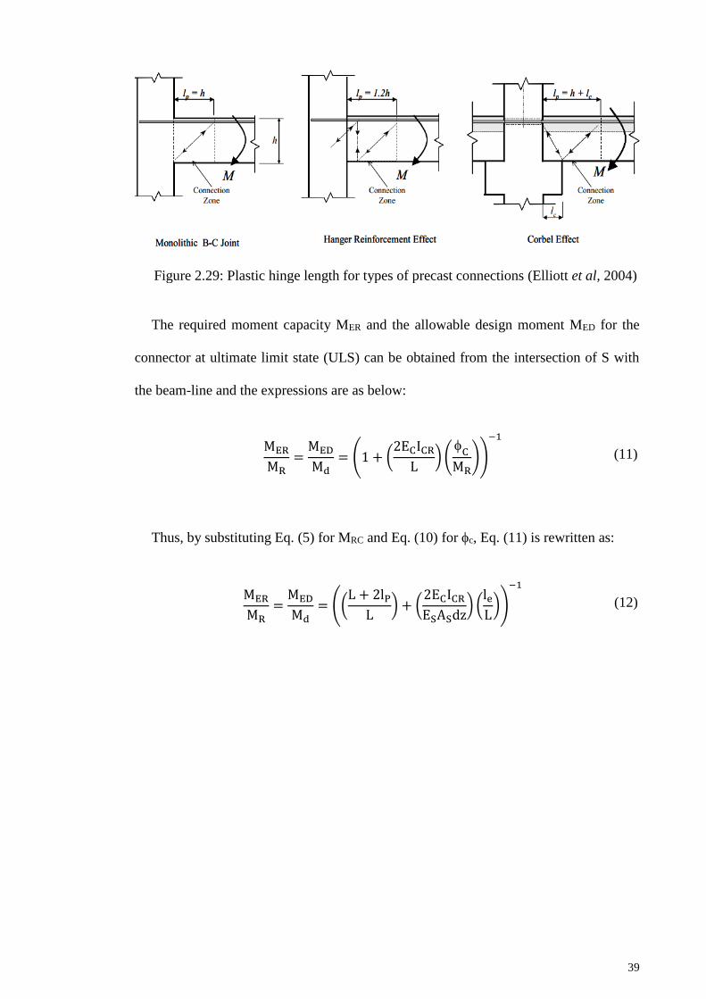
39
Figure 2.29: Plastic hinge length for types of precast connections (Elliott et al, 2004)
The required moment capacity MER and the allowable design moment MED for the
connector at ultimate limit state (ULS) can be obtained from the intersection of S with
the beam-line and the expressions are as below:
MER
MR=
MED
Md= (1 + (
2ECICR
L) (
C
MR))
−1
(11)
Thus, by substituting Eq. (5) for MRC and Eq. (10) forc, Eq. (11) is rewritten as:
MER
MR=
MED
Md= ((
L + 2lP
L) + (
2ECICR
ESASdz) (
le
L))
−1
(12)

40
CHAPTER 3: RESEARCH METHODOLOGY
3.1 Introduction
This study involved laboratory testing of a total of three (3) specimens. These
specimens are having the same geometric and material properties. Repetitive testing is
done to confirm the result. In order to verify the results, validation with analytical
method is made.
The steps taken to accomplish this study are divided in three (3) stages which are
design stage, experimental works stage and result analysis stage. The details about the
stages are described below:
i. Design stage
At this stage, an existing precast beam to column connection was selected.
Then, a new proposed precast beam to column connection was designed and
modified based on the existing precast connection. This proposed connection
is designed to fulfill such requirements which are able to resist moment
resistance, easy in constructing, fast in erection and cost effecive.
Architectural demand also is taken into account where no corbel used for this
connection. Architectures find it hard using corbel due to its limitation.
ii. Experimental works stage
This stage involves the preparation for laboratory testing for proposed precast
beam to column connection. The works involves are specimens fabrication at
site, assemblage specimen components at laboratory and specimens testing.
41
iii. Result analysis stage
At this stage, the results obtained from the experiment are analysed. The
analysis of result involve determining the moment resistance of the
connection, plotting the graph for moment rotation (M-) relationship, load
displacement relationship and beam line. Then, types of connection for
proposed precast beam to column connection is determined using connection
classification system according to Monforton’s Fixity Factor. Validation
testing result also made with analytical approach.
To simplified the methods, the flowchart below shows the chronology of the methods
(Figure 3.1).
Figure 3.1: The flowchart of the methods
Design Stage
• Selection of existing precast connection
• A new proposed precast connection wasdesigned and modified based on theexisting connection
Experimental Works Stage
• Specimens fabrication at site
• Assemblage specimen components atlaboratory
• Specimens testing
Result Analysis Stage
• Determine the moment resistance of theconnection
• Graph plotting for moment rotation (M-)relationship, load displacementrelationship and beam line
• Determine the Monforton’s Fixity Factor

42
3.2 Design Stage
This study started with proposal of precast beam to column connection. As
mentioned earlier, an existing precast beam to column connection was selected. Then, a
relevant precast connection was designed. This connection was designed based on
recommendation of BS8110:1997. This connection is called Billet Connection and in
this testing, the specimens were labelled as BIC 1, BIC 2 and BIC 3. The descriptions of
the connection are described in Section 3.2.1.
3.2.1 Description of the Connection
In this study, a new precast beam to column connection has been proposed and it is
hidden corbel connection. This connection using beam half joint and cast in steel insert
in the column (billet) and both components were jointed together. This connection is
modification of existing precast connection proposed by previous researcher. The
existing precast beam to column connection is shown in Figure 3.2.
Figure 3.2: Existing precast beam to column connection (Fib, 2008)

43
The modifications that have been made to the existing precast connection are the
location of additional top reinforcement bar to a certain level within the beam. Since the
top reinforcements are within the beam, only small amount of grout need to be used
instead of a lot of concrete topping for existing precast connection. Besides, the
proposed connection used the mechanical connector within the column to connect the
additional top reinforcement bar to the column. The proposed connection and its
detailing are shown in Figures 3.3, Figure 3.4 and Figure 3.5.
Figure 3.3: The proposed precast beam to column connection
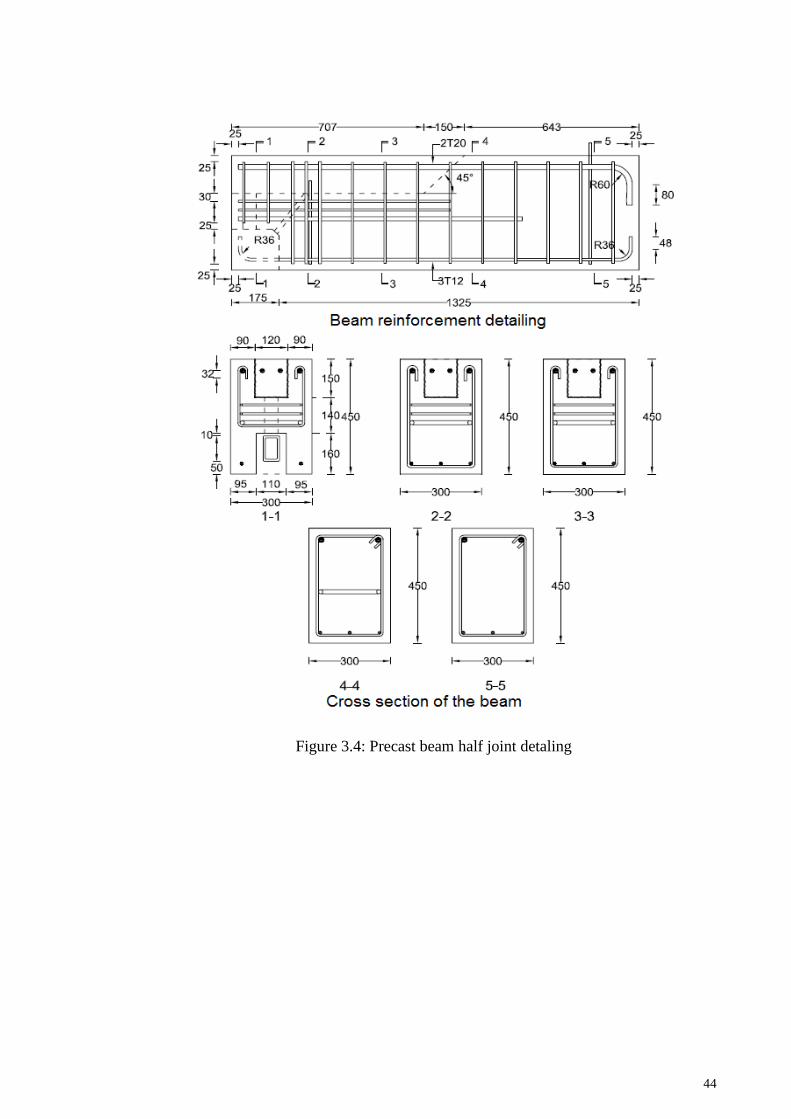
44
Figure 3.4: Precast beam half joint detaling
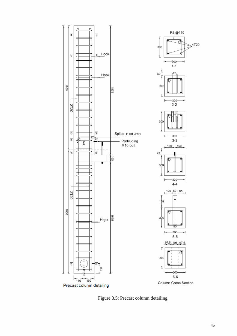
45
Figure 3.5: Precast column detailing

46
Basically, this connection was designed based on the recommendation of
BS8110:1997. This connection consists of steel insert with dowel to support the beam.
The steel insert is rectangular hollow section (RHS) of size 100 x 60 x 8mm with infill
concrete to make it stiffer. The dowel of 16mm diameter is connected between the steel
insert and the angle cleat. The cleat is then bolted to the column. The beam size used for
this connection is 300 x 450 mm and 300 x 300 mm for the column size. The top of the
beam has a recess of 150 mm deep and 860 mm length to permit the hand placement of
two (2) no. T16 mm rebar x 770 mm length anchored to the column using threaded
splice couplers. The tensile strength of the couplers must be greater than tension bar
which is 460 N/mm2. The concrete grade used for this specimen is 40 N/mm2 whilst
460 N /mm2 steel strength is used for the main bars (high tensile steel) and 250 N/mm2
steel strength for links and stirrups. All design calculations are shown in Appendix A.
3.3 Experimental Work
3.3.1 Fabrication at Site
All sample components (precast beam and precast column) were fabricated and
casting at Teraju Precast Sdn. Bhd at Dengkil, Selangor. All components were cast
using ready mix concrete with grade 40 concrete. The compressive strength test was
conducted by Teraju Precast Sdn. Bhd. at 28 days and all the concrete achieved the
required strength. Inspection was made to ensure the reinforcement and stirrup follow as
per drawing. Figure 3.6 to Figure 3.8 shows the construction work at site.

47
Figure 3.6: Tying the reinforcement Figure 3.7: Reinforcement inspection
Figure 3.8: Reinforcement caging ready to be put in to the mould
3.3.2 Sub Assemblage of Specimen Components at Laboratory
All assembly works for specimen’s components were done at Construction Research
Institute of Malaysia (CREAM)’s laboratory. The assembly works involved stages such
as erection of precast connection, preparation of formwork, grouting process, casting of
concrete at jointing part, curing process and finally painting process.
For assembling of precast column and precast beam, the precast column was lifted
using gantry crane and was placed into column support which restrained to the strong
floor (see Figure 3.9a). Then, the precast beam half joint was placed on the billet

48
projecting from the column face (column connection). Whilst at the other side of the
beam were seated on the temporary support.
The gap between beam and column was filled with grout and simple timber
formwork was formed (Figure 3.9b and 3.9c).
a) Assembling of precast column and
precast beam
b) Simple timber formwork for grouting
c) Close-up bottom formwork
Figure 3.9: Erection of connection
For grouting, Sika grout 215 with the strength of 50 N/mm2 at seven (7) days for
flowable mixing and 65N/mm2 at seven (7) days for pourable mixing was used to fill
the dowel holes in precast beam. For this connection, pourable mixing was selected. The
mixing proportion for pourable grout is shown in Table 3.1.
Column
support
Temporary
support
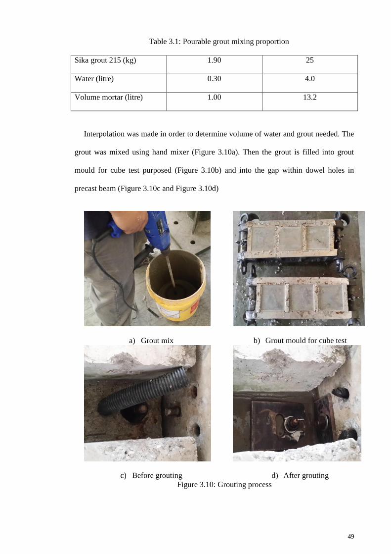
49
Table 3.1: Pourable grout mixing proportion
Sika grout 215 (kg) 1.90 25
Water (litre) 0.30 4.0
Volume mortar (litre) 1.00 13.2
Interpolation was made in order to determine volume of water and grout needed. The
grout was mixed using hand mixer (Figure 3.10a). Then the grout is filled into grout
mould for cube test purposed (Figure 3.10b) and into the gap within dowel holes in
precast beam (Figure 3.10c and Figure 3.10d)
a) Grout mix
b) Grout mould for cube test
c) Before grouting
d) After grouting
Figure 3.10: Grouting process

50
For concreting works, concreting only involved the small recess of 150mm deep and
860mm length, at the top of the beam. The concrete mix design is attached in Appendix
B. This area was concrete after two (2) no. T16 mm rebar x 770 mm length is placed
and anchored to the column using threaded splice couplers. The concreting work was
done at CREAM’s laboratory (Figure 3.11). Slump test was done in order to determine
the workability of the concrete (Figure 3.12).
Figure 3.11: Concrete mixing at laboratory
Figure 3.12: Slump test to determine the workability of concrete mixing

51
Total (8) eight test cubes for each concrete batch was prepared using 150mm mould.
The concrete was filled into mould with 3 (three) equal layers and must be fully
compact to reduce air trapped that might cause low concrete strength. Vibration table
was used to compact the concrete (Figure 3.13).
Figure 3.13: Concrete in moulds for cube test
At beam-column jointing part, a handheld concrete vibrator was used to compact the
concrete (Figure 3.14).
Figure 3.14: Concreting at jointing part
Handheld
concrete vibrator

52
Last work for specimen preparation was the painting process (Figure 3.15). The
whole specimen was paint with white colour wheareas this colour is suitable to be used
in observed the cracks and cracks marking.
Figure 3.15: Painting process of the whole specimen
3.3.3 Experimental Setup and Instrumentation
The setup for the testing is shown in Figure 3.16. The precast column was restrained
at both the top and bottom ends of the column. The top column was tied back to the
steel frame that was anchored to the strong floor while bottom column is restrained
using column support. This setup was designed to ensure there is no rotation for the
column while loading is applied to the beam. Reversible load is applied at a distance of
3d (where d is effective depth of the beam) from the column face. This action will
produce moment at connection until failure.

53
Figure 3.16: Experimental setup for flexural test
For instrumentation, LVDT (Linear Variable Displacement Transducer) was used to
capture displacement data from the experiment and total eight (8) numbers of LVDT
were used to measure displacements of precast beam and column. To record the
displacement values produces from LVDT, a data logger was used (Figure 3.17). Whilst
to measure the strain in steel reinforcement and concrete, three (3) types of strain
gauges is used which were steel strain gauge, concrete strain gauge and concrete rosette
strain gauge. The strain gauges used are shown in Figure 3.18 and Figure 3.19. The
overall instrumentation of this testing is shown in Figure 3.20 and Figure 3.21.
Figure 3.17: Data logger that used to capture data from LVDT and strain gauge

54
Figure 3.18 : Concrete strain gauge
Figure 3.19: Steel strain gauge

55
Figure 3.20: Location of LVDT and concrete strain gauges

56
Figure 3.21: Locations of steel strain gauges

57
3.3.4 Testing Procedure
The testing on connections was conducted at seven (7) days after concrete strength
reached 40±5 N/mm2. In order to study the stiffness of the connections, the bending
load (P) was applied in six (6) reversible cycles followed by monotonic loading up to
failure. The load was applied on precast beam at distance of 3d from the column face
(which is Lp =1350mm) and with the increment of 5kN. The load was reversed at first
crack loading, second crack loading and then an increasing load until the connections
were not capable of supporting any further bending moment.
3.4 Analytical Method
3.4.1 Moment-Rotation (M-) Calculation Technique
In order to plot the graph moment-rotation relationship, the values of moment,
rotation and stiffness need to be calculated as discussed in Section 3.4.1.1, Section
3.4.1.2 and Section 3.4.1.3 respectively.
3.4.1.1 Calculation of Moment
The moment, M was calculated by multiplying the applied load, P (recorded by
actuator) with the contraflexure length which is at the distance of 3d (1350mm) from the
face of the column and also the moment . This value was then added to the initial
bending moment of the selfweight of the beam. All of these are illustrated in Figure
3.22. The selfweight of beam is 4.86 kN (0.30m x 0.45m x 1.5m x 24 kN/m3). The
calculation of moment is as below:
Moment, M = [1.35P + 0.634 sw] kNm
= [1.35P + 0.634 (4.86)] kNm

58
=[1.35P + 3.081] kNm P : unit in kN
Figure 3.22: Typical details for moment calculation method
3.4.1.2 Calculation of Rotation
According to Hasan et al. (2011), there is no standard or normative method to
experimentally measure the relative beam to column rotation and variety techniques
have been used by various researchers. In this study, rotation () was determined from
Gorgun (1997). The rotation was determined from the relative vertical deflection of the
compression face of the beam with reference to the column. This method was also used
by Mahdi (1992) and Ferreira (1999). The connection rotation is determined from Eq.
13.
Connection rotation () = column rotation (column) – beam rotation (beam) (13)
The method to obtain beam rotation (beam) and column rotation (column) are as
below:
i. Beam rotation

59
Referring to Figure 3.23, LVDTs are mounted along the beam and labelled as
LVDT 6, LVDT 7 and LVDT 8 to measure the vertical deflection,
The relative rotation was produced as follows:
LVDT 6
=LVDT 6
x (14)
LVDT 7
=LVDT 7
y (15)
LVDT 8
=LVDT 8
𝑧 (16)
Thus, relative rotation,
LVDT 8−
LVDT 6=
LVDT 8−LVDT 6
z−x
(17)
The relative rotation was produced by dividing relative deflection with
relative distance of LVDT 8 and LVDT 6.
ii. Column rotation
The same method applies for column rotation. The LVDT 1, LVDT 2, LVDT
3, LVDT 4 and LVDT 5 were placed horizontally at the column. However, to
calculate the column rotation, only readings from LVDT 2 and LVDT 4 were
taken into account. Readings from LVDT 1 and LVDT 5 were adopted to
monitor any rotation at top and bottom column’s support. The calculation of
column rotation is as follows:
LVDT 2
=LVDT 2
a (18)

60
LVDT 4
=LVDT 4
b (19)
Thus, relative rotation,
LVDT 2+
LVDT 4=
LVDT 2+LVDT 4
a+b
(20)
The relative rotation was produced by dividing column relative deflection
with actual vertical distance of LVDT 2 and LVDT 4.
Figure 3.23 : Typical details for calculation of connection rotation
3.4.1.3 Calculation of Stiffness
The rotational stiffness (S), is calculated from the slope of the M- graph. In order to
calculate the stiffness, equation (4) in Section 2.6 is adopted. The equation is:
S = M
(21)

61
3.4.2 Beam Line Method
In the moment-rotation (M-) graph, the beam line intersects the vertical axis at
moment value which is the end moment of a fully fixed beam. Whilst at the horizontal
axis, the beam line intersects at rotation value which is rotation at the end of a simply
supported beam. In order to draw the beam-line, there is a need to calculate the end
moment of the connection and the rotation. The end moment of connection is obtained
from the equation M= F x z where this calculation involved the internal forces in the
connection (Refer Figure 3.24). For detail calculation, please refer Appendix C1.
Figure 3.24: Internal force in the connection
The rotation can be calculated once the moment is obtained. This is based on linear
interaction points of end moment and end rotation. This beam line having a gradient (m)
line of (refer to Figure 3.25). The detail calculation is shown in Appendix C2.

62
Figure 3.25: The gradient, m of beam line (Elliott et al., 2003)
3.4.3 Connection Classification
For the connection classification based on Monforton’s fixity factor (), the value of
fixity factor () is obtained from Equation (3). The detail calculation is also shown in
Appendix C2.

63
CHAPTER 4: RESULTS AND DISCUSSIONS
4.1 Introduction
In this chapter, the results obtained from the experiment are presented in the form of
tables and graphs. Three (3) similar specimens namely BIC 1, BIC 2 and BIC 3 were
tested under reversed cyclic loading. The results are discussed in these nine (9)
subtopics below. The subtopics are:
i. Material testing (Section 4.2)
ii. Moment rotation (M-) relationship (Section 4.3.1)
iii. Load displacement relationship (Section 4.3.2)
iv. Load strain curve (Section 4.3.3)
v. Connection Classification (Section 4.3.4)
vi. Failure modes and cracks pattern (Section 4.3.5)
vii. Analytical result (Section 4.4)
viii. Comparison of result between analytical and experimental method (Section
4.5)
ix. Discussion (Section 4.6)
4.2 Material Testing
4.2.1 Sika Grout 215
For grouting, Sika grout 215 with the strength 50 N/mm2 at seven (7) days for
flowable mixing and 65 N/mm2 at seven (7) days for pourable mixing is used to fill the
dowel holes in precast beam. For this connection, pourable mixing was selected. The
compressive strength test were carried out using 3000 kN Concrete Compression
Machine (Model : Controls) and with accordance to MS 26: Part 2: 1991 Section Three

64
( Method for Determination of Compressive Strength of Concrete Cubes). The cube test
result at seven (7) days for grout is shown in Table 4.1 below.
Table 4.1: Grout strength for the specimens
Connection
Specified cube
strength
N/mm2
Actual cube strength, N/mm2
(At testing day)
Cube 1 Cube 2
BIC 1 65 63 69
BIC 2 65 62 67
BIC 3 65 64 66
4.2.2 Concrete
For concrete, it is designed for 40 N/mm2 at seven (7) days. The concrete mix design
is attached in Appendix B. Two types of test were carried out which are slump test and
compressive strength test.
For slump test, MS 26: Part 1: 1991 Section Two (Method for Determination of
Slump) was adopted. The slump test was carried out to ensure the workability of the
mix. The slump test was passed where the workability is within the ranged of 60-
180mm as per designed.
For compressive strength test, the test were carried out using 3000 kN Concrete
Compression Machine (Model : Controls) and with accordance to MS 26: Part 2: 1991
Section Three ( Method for Determination of Compressive Strength of Concrete Cubes).
The results for cube test at testing day are shown in Table 4.2 below.
Table 4.2: Concrete strength infill for the specimens
Connection
Specified cube
strength
N/mm2
Actual cube strength, N/mm2
(At testing day)
Cube 1 Cube 2
BIC 1 40 47 45
BIC 2 40 40 49
BIC 3 40 53 46

65
4.2.3 Tension Reinforcement (T16)
Tensile test was done for hand placement of two (2) no. T16 mm rebar x 770 mm
length that anchored to the column using threaded splice couplers. Tensile test was
carried out in accordance with MS 146: 2006 Clause 16 (Mechanical Properties –
Tensile) using 2000 kN Universal Testing Machine (Model : Shimadzu). The results
for tensile test are shown in Table 4.3.
Table 4.3: Tensile test results for tension reinforcement
Reinforcement Diameter
(mm)
Length of
bar (mm)
Yield load
(kN)
Tensile load /
ultimate load (kN)
Bar 1 16 800 103.93 118.62
Bar 2 16 800 104.24 119.08
4.3 Results from Experiment
The general results for all the testing are shown in Table 4.4.
Table 4.4: Summary of results obtained from experiments
Connection Dia. of
tension bar
Moment at
first crack,
MCR (kNm)
1Moment
capacity,
MRC (kNm)
2Ultimate
Moment,
MU (kNm)
Ratio
MU/MRC
BIC 1
2 x 16
30
77.94
105.45 1.35
BIC 2 29 97.77 1.25
BIC 3 29 80.48 1.03
Average 29.33 77.94 94.57 1.21
1 The calculation of MRC is based on the equilibrium of all forces present in the
connection (it is calculated at the face of the column). The internal level arm, z is
the resultant of the various horizontal forces such as threaded dowel and
reinforcing tie bars (Figure 4.1). It is assumed that the forces can contribute to the
moment capacity. This calculation is without partial safety factors.
2 Ultimate moment capacity of connection obtained from testing
From the results shown in Table 4.4, the maximum moment of connections, MU is
greater than calculated moment resistance, MRC. The calculation of MRC is based on the
equilibrium of all forces in connection and it is calculated at the face of the column. An

66
assumption is made for MRC which is all structural components present at the column
face had achieved their full yield capacity. It is also assumed that compressive stress in
the concrete infill is equal to 0.67 fcui (compressive strength of grout). By using this
assumption, the average value of MU/MRC is 1.21 with the range from 1.03 to 1.35. The
ultimate moment, MU of BIC 3 is significantly low compared to BIC 1 and BIC 2.
Figure 4.1 : Internal lever arm, z for reinforcement bar and dowel
4.3.1 Moment Rotation (M-) Relationship
The results for moment-rotation are interpreted in graph and it is shown in Figures
4.2 to 4.4. The graphs were plotted using data in Appendix D.
Figure 4.2: Moment-rotation (M-) graph for BIC 1
0
10
20
30
40
50
60
70
80
90
100
110
120
0 5 10 15 20 25 30 35 40 45
Mo
me
nt
(k
Nm
)
Rotation (milirad)
BIC 1
Beam Line BIC 1
EBIC 1
Moment-Rotation (M-) Graph (BIC 1)

67
Figure 4.3: Moment-rotation (M-) graph for BIC 2
Figure 4.4: Moment-rotation (M-) graph for BIC 3
0
10
20
30
40
50
60
70
80
90
100
110
120
0 5 10 15 20 25 30 35 40 45
Mo
me
nt
(k
Nm
)
Rotation (milirad)
BIC 2
Beam Line BIC 2
EBIC 2
Moment-Rotation (M-) Graph (BIC 2)
0
10
20
30
40
50
60
70
80
90
100
110
120
0 5 10 15 20 25 30 35 40 45
Mo
me
nt
(k
Nm
)
Rotation (milirad)
BIC 3
Beam Line BIC 3
EBIC 3
Moment-Rotation (M-) Graph (BIC 3)

68
From the graph, the point of intersection (E) is determined where the end moment
and the corresponding rotation of both beam and connection can be obtained. These
intersections give the values of ME and E and it is summarized in Table 4.5. Then, this
value is used in calculation of secant stiffness (SE) from Equation (1) and stiffness
factor (KS) from equation (2) as given in Table 4.5.
Table 4.5: Results obtained from M- graph
Connection
1Moment at
point E (ME)
(kNm)
Rotation at
point E (E)
(milirad)
Secant stiffness
(SE)
Stiffness factor
KS
BIC 1 43.0 10.39 4.14 0.610
BIC 2 48.1 8.70 5.53 0.820
BIC 3 42.0 10.6 3.96 0.577
Average 44.4 9.90 4.54 0.669
1 End moment and end rotation of both beam and connection / allowable moment
capacity of a connection
The M- plots for BIC 1, BIC 2 and BIC 3 specimens are shown in Figure 4.5.
Figure 4.5: M- graph with beam-line for all specimens of connection
0
10
20
30
40
50
60
70
80
90
100
110
120
0 5 10 15 20 25 30 35 40 45
Mo
me
nt
(k
Nm
)
Rotation (milirad)
BIC 1
BIC 2
BIC 3
Beam Line BIC 1
Beam Line BIC 2
Beam Line BIC 3
EBIEBI
EBIC
3
EBIEBI
EBIC
3
EBIEBI
EBIC
3
EBIEBI
EBIC
3
EBIEBI
EBIC
3
EBIEBI
EBIC
3
EBIEBI
EBIC
3
EBIEBI
EBIC
3
EBIEBI
EBIC
3
EBIEBI
EBIC
3
EBIEBI
EBIC
3
EBIEBI
EBIC
3
EBIEBI
EBIC
3
EBIEBI
EBIC
3
EBIEBI
EBIC
3
EBIEBI
EBIC
3
EBIEBI
EBIC
3
EBIEBI
EBIC
3
EBIEBI
EBIC
3
EBIC 1
EBIC 2
EBIC 3
Moment-Rotation Graph for All Connections (BIC 1, BIC 2 and BIC 3)

69
From the Figure 4.5 . All specimens failed beyond the beam-line which means that
the connection has sufficient ductility and achieved required strength to be considered
as a semi-rigid connection.
4.3.2 Load Displacement Relationship
Load displacement graph is drawn according to Park and Paulay (1975) (refer
Figures 4.6 to 4.8. All the graphs were drawn based on displacement data obtained from
LVDT 8. Besides, the ductility factors also calculated according to Park and Paulay
(1975). The graphs were plotted using data in Appendix E.
Figure 4.6: Load displacement graph for BIC 1
0
10
20
30
40
50
60
70
80
0 2 4 6 8 10
Lo
ad
(kN
)
Displacement (mm)
Load Displacement Relationship
BIC 1
First crack = 19.96 kN
Ultimate
displacement, u = 7.93 mm
Ultimate load = 75.74 kN
Displacement at the
First yield, y = 5.31 mm
Load at yield = 55.52 kN

70
Figure 4.7: Load displacement graph for BIC 2
Figure 4.8: Load displacement graph for BIC 3
0
10
20
30
40
50
60
70
80
0 5 10 15 20
Lo
ad
(kN
)
Displacement (mm)
Load Displacement Relationship
BIC 2
First crack = 19.49 kN
0
10
20
30
40
50
60
70
-1 0 1 2 3 4 5 6 7
Lo
ad
(kN
)
Displacement (mm)
Load Displacement Relationship
BIC 3
First crack = 19.37 kN
Ultimate
displacement, u = 15.4 mm
Ultimate load = 70.0 kN
Ultimate
displacement, u = 6.57 mm
Ultimate load = 57.22kN
Displacement at the
First yield, y = 4.02 mm
Load at yield = 49.72 kN
Displacement at the
First yield, y = 4.62 mm
Load at yield = 42.91 kN

71
Based on the graph, the summary of the results are shown in Table 4.6.
Table 4.6: Summary of results from load displacement graph
Connection Yield load
(kN)
Ultimate load
(kN)
Displacement
at yield load
y(mm)
Displacement
at ultimate
load u(mm)
Ductility
factor = u
y
BIC 1 55.52 75.74 5.31 7.93 1.49
BIC 2 49.72 70.00 4.02 15.40 3.83
BIC 3 42.91 57.22 4.62 6.57 1.42
From the results, it is shown that BIC 1 and BIC 3 is at full elastic condition while
BIC 2 achieve partial ductile (Refer Table 2.3). All the connections are capable to
undergo inelastic deformation after the first crack. The connections also can maintain
sufficient strength to support futher load and give warning of failure to prevent total
collapse. The connections can be considered to have satisfactory ductility.
4.3.3 Load Strain Curve
The load strain curve is plotted based on load strain data obtained from steel strain
gauge 5 (S5) and steel strain gauge 6 (S6) (refer Figure 3.21). The both strain gauges are
fixed at two (2) points on left and right tension bar (T16). The curve plotted
demonstrated the strain behaviour of tension bars during testing (refer Figure 4.9 to
Figure 4.11). Based on the graph, the summary of the results is shown in Table 4.7. The
graphs were plotted using data in Appendix F.

72
Figure 4.9: Load strain graph for BIC 1
Figure 4.10: Load strain graph for BIC 2
-10
0
10
20
30
40
50
60
70
80
0 500 1000 1500 2000
Lo
ad
(kN
)
Strain, (x10-6)
Load Strain Relationship (Steel) -BIC 1
S5
S6
0
10
20
30
40
50
60
70
80
0 500 1000 1500 2000 2500
Lo
ad
(kN
)
Strain, (x10-6)
Load Strain Relationship (Steel)-BIC 2
S5
S6
First crack = 19.96 kN
First crack = 19.49 kN
Ultimate load = 70.0 kN
Yield load = 55.52 kN
Yield load = 49.72 kN
Ultimate load = 75.74 kN

73
Figure 4.11: Load strain graph for BIC 3
Table 4.7: Summary of results from load strain graph
Connection Strain Gauge
Strain at cracking
load
cr (x10-6)
Strain at yield
load
y (x10-6)
Strain at ultimate
load
u (x10-6)
BIC 1 S5 345 775 1574
S6 175 254 339
BIC 2 S5 218 405 2085
S6 318 519 1981
BIC 3 S5 27 47 86
S6 35 120 168
From the graphs, it can be seen that the load strain curve behaved in three (3) stages
which are:
a) Before the first crack
The load strain curve of tension bars (T16) is in linear elastic
b) Between the first crack and initial yielding
-10
0
10
20
30
40
50
60
70
-200 -150 -100 -50 0 50 100
Lo
ad
(kN
)
Strain, (x10-6)
Load Strain Relationship (Steel)-BIC 3
S5
S6First crack = 19.37 kN
Yield load = 42.91 kN
Ultimate load = 57.22 kN

74
The load strain curve of tension bars (T16) is tend to be nonlinear
c) After the initial yielding
The load strain curve of tension bars (T16) are approximately a horizontal straight
line which means that the load remains almost the same while the strain still on
increasing.
At the ultimate load (failure point) (refer Table 4.7), it is observed that the strain
value for BIC 3 (u : 0.000086 (S5) and 0.000168 (S6) are significantly low compared
to BIC 1 (u : 0.001574 (S5) and 0.000339 (S6) and BIC 2 (u : 0.002085 (S5) and
0.001981 (S6). Bar slippage failure was happened in BIC 3 (discussed in 4.3.5). The
bond slip in tension bars was happened at the early testing indicates by low increment
of strain values.
In terms of stiffness, it is observed there are losses of stiffness for BIC connection.
The changes in the slope of the curve (load strain) indicate there are losses of stiffness
in the connection (indicates by black line for S5 and red line for S6). For BIC 1 and BIC
2, the losses can be obtained (refer Figure 4.12 and Figure 4.13) but for BIC 3, the
losses can not be established since BIC 3 (refer Figure 4.14) having bond slip at the
early testing. The purposed of loading and unloading condition load is to observed the
stiffness of the connection

75
Figure 4.12: Stiffness losses of BIC 1
Figure 4.13: Stiffness losses of BIC 2
-10
0
10
20
30
40
50
60
70
80
0 500 1000 1500 2000
Lo
ad
(kN
)
Strain, (x10-6)
Load Strain Relationship (Steel) -BIC 1
S5
S6
0
10
20
30
40
50
60
70
80
0 500 1000 1500 2000 2500
Lo
ad
(kN
)
Strain, (x10-6)
Load Strain Relationship (Steel)-BIC 2
S5
S6

76
Figure 4.14: Stiffness losses of BIC 3
4.3.4 Connection Classification
According to Hasan et al. (2011), in order to quantify the rotational stiffness (SE) of
the connection, the Monforton’s Fixity Factor (), as given in Equation (3) is adopted.
The values from the calculation are shown in Table 4.8.
Table 4.8: Monforton’s Fixity Factor value for BIC
Connection Fixity Factor,
BIC 1 0.450
BIC 2 0.522
BIC 3 0.435
Average 0.469
Then, this value is referred to the classification system for beam to column
connection (Figure 2.24) which is reproduced after Ferreira et al. (2005). Based on the
classification, the connection falls under Zone III which is classified as semi-rigid
connection with medium strength.
-10
0
10
20
30
40
50
60
70
-200 -150 -100 -50 0 50 100
Lo
ad
(kN
)
Strain, (x10-6)
Load Strain Relationship (Steel)-BIC 3
S5
S6

77
4.3.5 Failure Modes and Crack Patterns
The crack patterns of BIC specimens are shown in Figure 4.15 to Figure 4.17. For all
specimens, first cracks started to appear at 19.96kN (BIC 1), 19.49kN (BIC 2) and
19.37kN (BIC 3) respectively and all occured near the column. Possible failures that
might occur at the connection region were highlighted by Meinheit and Jirsa (1981). For
BIC, all specimens exhibited flexural cracking in the beam and column regions
followed by diagonal cracking in the connection itself. Further load increments have
extended the cracks. Based on the damage, plastic hinged had formed in the beam at
face of the column. It means that ultimate moment resistance of the beam was reached.
Besides, splitting cracks were also observed within the connection region.
(a) First crack at 19.96 kN for BIC 1
First crack
at 19.96 kN

78
(b) First crack at 19.49 kN for BIC 2
(c) First crack at 19.37 kN for BIC 3
Figure 4.15: First crack for all connections happened at column
First crack at
19.49 kN
First crack at
19.37 kN
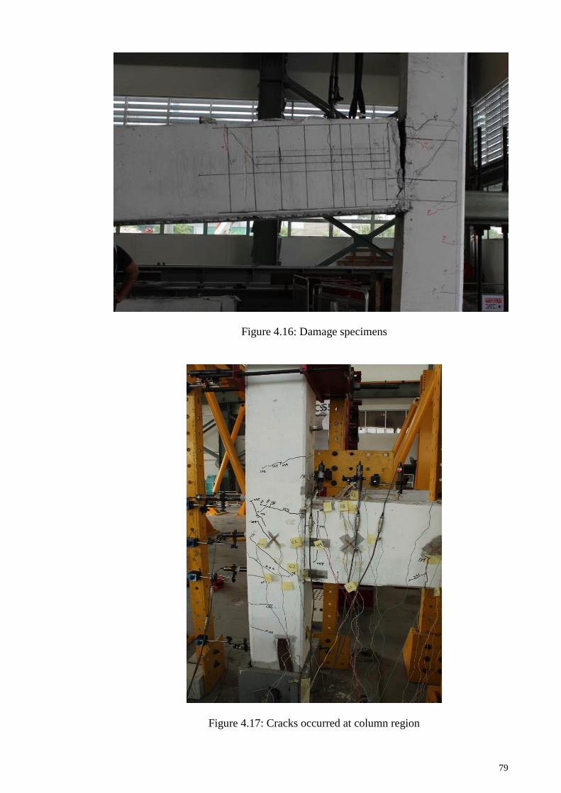
79
Figure 4.16: Damage specimens
Figure 4.17: Cracks occurred at column region

80
The two additional tension bars (T16 rebar) that were used together with the splice
connector had contributed significant to increase in moment resistance to this
connection. Two modes of failure were observed, namely bar fractured and bar
slippage. For BIC 1 and BIC 2, the failure mode was found to be bar fractured (see
Figure 4.18) while for BIC 3 was bar slippage (see Figure 4.19 and Figure 4.20). The
bars with fractured modes of failure (BIC 1 and BIC 2) can resist the moment up to
105.45 kNm while the bars with slippage modes of failure (BIC 3) can only resist untill
80.48kNm only. According to Shaedon (2012), steel bar is fractured when they
achieved their ultimate capacity, while bar slippage is failed when the steel bar being
pulled out from the splice connector. For bar fractured failure, the splice connector
provides adequate interlocking mechanism to resist steel bar from slipping out. For BIC
3 bar slippage happened because of less efficient bond between steel bar and splice
connector. The steel bars and splice connector was not well secured due to defect of
fabrication work.
Figure 4.18: Bar fractured failure for BIC 1 and BIC 2

81
Figure 4.19: Bar slipped failure at the BIC 3 connection
Figure 4.20: Bar slipped from the splice connector
4.4 Analytical Result
The results of analytical prediction of moment and rotation determine from Equation
(5) to Equation (12) are shown in Table 4.9.

82
Table 4.9: Predicted moment resistance, rotation, stiffness of the connection,
interception point and fixity factor for BIC connection
Connection
Moment
capacity
(kNm)
Connection
rotation ()
(milirad)
Secant
stiffness
(SE)
Intersection
at beam line
kNm (E)
Fixity
Factor
()
Classification
(Figure 2.24)
Predicted 77.95 5.25 14.82 67.5 0.745 Zone IV
The predicted value shows that moment capacity of connection is 77.95 kNm and it
falls in Zone IV which is semirigid connection with strength.
4.5 Comparison of the Result
The comparison between experimental result and analytical prediction is shown in
Table 4.10 and also interpreted in graph (Figure 4.21)
Table 4.10: Comparison between experimental result and analytical prediction
Connection
Moment
capacity
(kNm)
Connection
rotation ()
(milirad)
Secant
stiffness
(SE)
Intersection
at beam line
kNm (E)
Fixity
Factor
()
Classification
(Figure 2.24)
Predicted 77.95 5.25 14.82 67.5 0.745 Zone IV
Experiment 94.57 9.90 9.55 44.4 0.469 Zone III
The results show that the predicted value overestimates the experimental results (as
shown in Figure 4.12). The predicted value may be increased if the contributions of
mechanical parts (horizontal bolt, dowel and billet) are also included in the calculation
of c. In the current model, reinforcement bars is the dominant factor in the value for c.

83
Figure 4.21 Experimental and predicted stiffness for BIC connection
4.6 Discussion
Among this three (3) test carried out, it is found that the reading for horizontal
deflection cannot well established for BIC 1 whereas no relative deflection can be
calculated. This is because the LVDT 7 toppled during the testing (refer Figure 4.22),
while the reading for LVDT 6 is not well represented the beam deflection. So, only the
reading captured from LVDT 8 is used to plot the graph. Thus, the plotted look smooth
seems no failure occurred to this connection.
Tested for BIC
0
Predicted for BIC
0
10
20
30
40
50
60
70
80
90
100
110
120
0 5 10 15 20 25 30 35 40 45
Mo
me
nt
(k
Nm
)
Rotation (milirad)
BIC 1BIC 2BIC 3Beam Line BIC 1Beam Line BIC 2Beam Line BIC 3Tested for BICPredicted stiffness for BIC
EBIEBI
EBIC
3
EBIEBI
EBIC
3
EBIEBI
EBIC
3
EBIEBI
EBIC
3
EBIEBI
EBIC
3
EBI
EBIC
3
EBI
EBIC
3
EBI
EBIC
3
EBI
EBIC
3
EBI
EBIC
3
EBI
EBIC
3
EBI
EBIC
3
EBI
EBIC
3
EBI
EBIC
3
EBI
EBIC
3
EBI
EBIC
3
EBIC
3
EBIC
3
EBIC
3
Comparison between Predicted Approach with Experimental Result

84
Figure 4.22: LVDT 7 toppled during testing
For BIC 3, the ultimate moment (MU) obtained is the lowest compared to BIC 1 and
BIC 2 and the value is quite significant. As mentioned earlier, this connection having
bar slippage for the additional tension bar while the two others having bar fractured. It is
due the two (2) no. of T16 (tension bar) is not well secure to the column splice effects
from fabrication defect in beam. Thus, it is important to ensure this bar is well secured
since this bar is a tension member that resists moment in connection.
Besides, for analytical method, it is needed to establish the contribution of
mechanical parts in equation since this value also contributes to the important
parameters in connection.

85
CHAPTER 5: CONCLUSIONS AND RECOMMENDATIONS
5.1 Conclusion
Based on the experimental studies of a new proposed precast beam to column
connection and analytical prediction, the following conclusion can be drawn:
i. The maximum moment resistance of proposed connections obtained from the
test, MU = 93.95 kN, and it is greater than the calculated moment resistance,
MRC (theoretical prediction) which is 77.94 kN, whereas the ratio connection
failure load MU/MRC = 1.21.
ii. The analysis result shows that BIC is a semirigid connection with medium
strength in Classification System based on Monforton’s Fixity Factors,,
(meaning = 0 pinned and = 1 fully rigid). The for the connection is 0.469
which falls in Zone III.
iii. The predicted value overestimates the experimental results. By neglecting the
contribution of mechanical parts (horizontal bolt, dowel and billet) in the
calculation of c, has increased the analytical results. Reinforcement bars are the
dominant value ofc.
iv. The ductility of the connections are considered as satisfactory since the value for
for ductility factor is greater than 1 (ductility factor = 1 : full elastic condition).
The results from testing obtained that ductility factor BIC 1 = 1.49 , BIC 2 =
3.83, BIC = 1.42.
v. In terms of connection behaviour, BIC connection has sufficient ductility and
achieved required strength to be considered as a semi-rigid connection since it
fails beyond the beam-line. Plastic hinge formation was observed in the beam;
hence the ultimate moment resistance of the beam was reached. Besides, the two
(2) no. of T16 rebar (tension bar) which were anchored to the column using
thread splice coupler play an important role in determining the moment

86
resistance of the connection. The bars with fractured modes of failure (BIC 1
and BIC 2) can resist the moment up to 105.5 kNm while the bars with slippage
modes of failure (BIC 3) can resist till 79.45 kNm only.
5.2 Recommendation
The recommendations for future study for precast beam to column connection are:
i. All the instrumentation used for the testing should be properly setup to avoid
errors during experimental.
ii. Further study to develop more theory of analytical as an alternative to predict
the behaviour of connection. This will give some advantages/ help to
designers who are unable to do experimental works.
iii. Further design and testing for different type of connection which can resist
moment and also to fulfill architectural demand are recommended to be
carried out.
iv. Parametric study on the behaviour of precast beam column connection using
finite element method.

87
REFERENCES
Abd. Rahman, A. B., & Abdul Rahim, G. (2006). Investigation on the Performance of
Moment Beam-to-Column Connections for Precast Concrete Frames, Malaysian
Science and Technology Congress, 2006, Kuala Lumpur, Malaysia.
British Standards Institute (1997) BS8110, Part 1, Structural use of concrete - Code of
practice for design and construction, BSI, London.
CIDB (2003). Industrialised Building System (IBS) Roadmap (2003-2010).
Construction Industry Development Board (CIDB), Kuala Lumpur.
Department of Public Works (2002), ISO-1726-2002 : Planning Standard Earthquake
Resistance of Building Structures
Diaz, C., Marti, P., Victoria, M., & Querin, O. M. (2011). Review on the Modelling of
Joint Behaviour in Steel Frames. Journal of Constructional Steel Research, 67,
741-758
Dolan C. W., Stanton J. F. & Anderson, R. G. (1987). Moment Resistant Connections
and Simple Connections. PCI Journal, 32, No.2, 67-74.
Elliott K. S., Davies G., Gorgun H.,& Mohammad Reza A. (1998). The Stability of
Precast Concrete Skeletal Structures. PCI Journal 1998,43, No.2, 42-61.
Elliott K.S., Davies G., Gorgun H., & Mohammad Reza A. (1998). The Stability of
Precast Concrete Skeletal Structures. PCI Journal,43, No.2, 42-61.
Elliott, K. S. (1996). Multi Storey Precast Concrete Framed Structures. United
Kingdom: Blackwell science Ltd.
Elliott, K. S. (2002). Precast Concrete Structure. United Kingdom: Butterworth-
Heinman.
Elliott, K. S. and Jolly, C. K. (2013). Multi-Storey Precast Concrete Framed Structures,
2nd ed., John Wiley, London, pp.421.
Elliott, K. S., Davies, G., Ferreira, M., Halil, G., & Mahdi, A. A. (2003). Can Precast
Concrete Structures be Designed as Semi-Rigid Frames?.Part 1: The
Experimental Evidence. The Structural Engineer, 81/16, 14-27.
Elliott, K. S., Davies, G., Ferreira, M., Halil, G., & Mahdi, A. A. (2003). Can Precast
Concrete Structures be Designed as Semi-Rigid Frames?.Part 2: Analytical
Equations and Column Effective Length Factors. The Structural Engineer,81/16,
28-36
Elliott, K. S., Ferreira, M. A., & El Debs, M.K. (2004). Strength-Stiffness Requirement
Approach for Semi-Rigid Connections in Precast Concrete Structures,
International Conference on Concrete Engineering and Technology (CONCET
2004), Kuala Lumpur, Malaysia.

88
Elliott, K. S., Ferreira, M., de Aranjo, D., & El Debs, M. (2005). Analysis of Multi-
storey Precast Frames considering Beam-column Connections with Semi-rigid
Behaviour, Keep Concrete Attractive, FIB Symposium, Budapest, p496-501.
Ferreira, M. (1993). Study of Semi-Rigid Behaviour of Connections Applied to the
Linear Analysis of Precast Concrete Plane Frames. Msc Dissertation. School of
Engineering of Sao Paulo, Brazil.
Ferreira, M. (1999). Deformability of Beam-Column Connection in Precast Concrete
Structures. PhD. Thesis, University Of Nottingham, United Kingdom.
Ferreira, M. A., & Elliott, K. S. (2002). Strength- Stiffness Requirement Approach for
Semi-Rigid Connections in Precast Concrete Connections. Report. University of
Nottingham, United Kingdom.
Ferreira, M., Elliott, K. S., de Aranjo, D., & El Debs, M. K. (2005). Analysis of Multi-
storey Precast Frames Considering Beam-Column Connection with Semirigid
Behaviour, Keep Concrete Attractive, FIB Symposium, Budapest, May 23-25
2005,(pp. 496-501).Hungary
Ferriera, M. A., El Debs, M. K., & Elliott, K. S. (2003). Analysis of Multi-storey
Precast Frames with Semi-Rigid Connections. Brazilian Conference on
Concrete, IBRACON 2003, 45th Brazilian Concrete Congress, Brazilian
Concrete Institute - IBRACON, Vitoria, Brazil.
Fib (2008). Structural Connection for Precast Concrete Buildings. Bulletin, 43, pp.295.
FIP Commission on Prefabrication, (1986). Design of Multy Storey Precast Concrete
Structures. London : Thomas Telford Ltd.
Gorgun, H. (1997). Semi-rigid Behaviour of Connections in Precast Concrete
Structures. PhD. Thesis, University of Nottingham, United Kingdom.
Hamil, S. J., & Scott, R. H. (1999). Development in High Strength Concrete Beam-
Column Connection Design. University of Durham, United Kingdom.
Hanson, N. W., & Corner, H. W. (1967). Seismic Resistance of Reinforcesd Concrete
Beam-Column Joint.Portland Cement Association Research and Development.
Hasan, S., Elliott, K. S., & Ferreira, M. (2011). An Experimental Investigation On The
Moment Continuity Of Precast Concrete Beam-Column Connections Under
Gravity Loads, Proceeding of fib Symposium Prague.Czech Republic
Kooi, L. T. (2005). Behaviour of Precast Beam to Column Connection with Hidden
Corbel. Masters Thesis, Universiti Teknologi Malaysia, Johor.
Leong, D. C. P. (2006). Behaviour of Pinned Beam-To-Column Connections for Precast
Concrete Frames. Master Thesis, Universiti Teknologi Malaysia, Johor
Ling, N. Y. (2004). Behaviour of Beam-to-Column Connection in Precast Concrete
Structure. Masters Thesis, Universiti Teknologi Malaysia, Johor.

89
Loo, Y. C. & Yao, B.Z. (1995). Static and Repeated Load Tests on Precast
ConcreteBeam-to-Column Connections. PCI Journal , 40 No.2, 106-115.
Mahdi, A. A. (1992). Moment Rotation Effects on Stability Columns in Precast
Concrete Structures. PhD. Thesis, University of Nottingham, United Kingdom.
Marcakis, K. & Mitchell, D. (1980). Precast Concrete Connection with Embedded Steel
Members. PCI Journal, 25, No.4, 88-115
Meinheit, D. F., & Jirsa, J. O. (1981). Shear Strength of R/C Beam Column
Connections. Journal of Structural Engineering. 107, 2227-2244.
Monforton, G. R. & Wu, T. S. (1963). Matrix Analysis of Semi-rigidly Connected
Frames, Journal of Structural Division, Vol 89, No. 6.
Park, R. (1988). Ductility Evaluation from Laboratory and Analytical Testing.
Proceeding of Ninth World Conference on Earthquake Engineering. August 2-9
1988, Kyoto, Tokyo.
Park, R. & Paulay, T. (1975). Reinforced Concrete Structures. New York: John Wiley
& Sons.
PCI Committee on Connection Detail (1988). PCI Manual on Design of Connection for
Precast Prestressed Concrete.
Shaedon, S. (2012). Kelakuan Sambungan Bar Sanbat dengan Bar Pilin dan Bar Tegak
sebagai Sambungan untuk Dinding Konkrit Pratuang. Master Thesis. Universiti
Teknologi Malaysia. Johor.
Song, H. J. (2004). Nonlinear Finite Element Analysis of Precast Beam to Column
Connection. Masters Thesis,Universiti Teknologi Malaysia, Johor.
Stanton, J. F., Anderson, R. G., Dolan, C., & McCleary, D. E. (1986). Moment
Resistant Connections and Simple Connections, PCI Special Research Project,
No. 1 / 4.
Trikha, D. N., & Abang Ali, A. A. (2004). Industrialised Building Systems. Universiti
Putra Malaysia Press, Construction Development Board.
Vambersky, J. N. J. A. (1990). Mortar Joints Loaded in Compression, Prefabrication of
Concrete Structures. International Seminar Delft University of Technology,
Delft University Press, Oct., pp.167-180
Waddel, J. J. (1974). Precast Concrete : Handling and Erection . American Concrete
Institute. pp.73-87.

90
LIST OF PUBLICATIONS AND PAPERS PRESENTED
Published conference paper
Wan Bidin, W.N., Ibrahim, Z. & Ramli, N. H. (2009). Precast Beam to Column
Connection by Using Different Modular Size of Components, International
Conference Technical Postgraduate (TECHPOS) 2009, Kuala Lumpur.
Submitted journal paper
W. N. Wan Bidin, Z. Ibrahim, N. H. Ramli Sulong, Z. Abd. Hamid, A. H. Abdul
Rahim (2015). Full Scale Testing of Precast Beam-Column Connection Using
Billet Connector Subjected to Reversible Loading. Structural Engineering and
Mechanics Journal

91
APPENDICES
Appendix A : Design Calculation
A1 : Beam Half Joint Design

92

93

94

95

96

97

98
A2 : Steel Insert Design

99

100

101

102

103
A3 : Beam Design

104
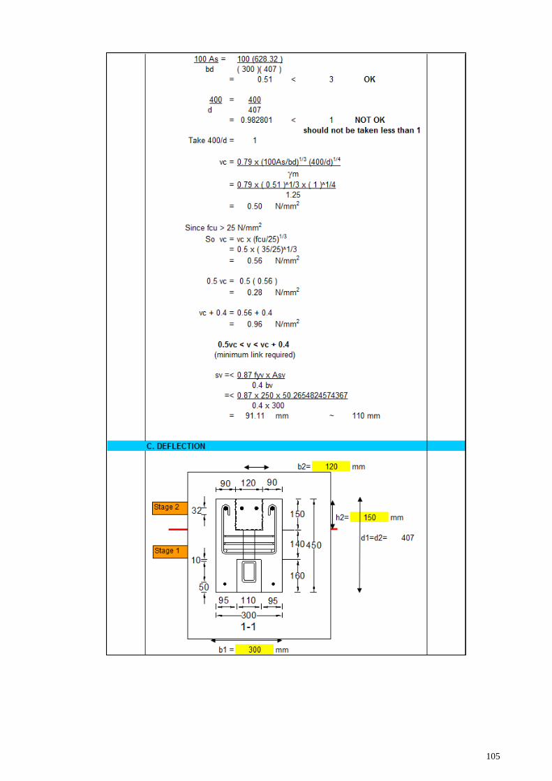
105

106

107
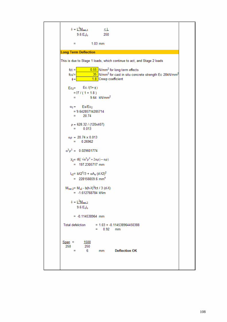
108

109
Appendix B : Concrete Mix Design

110
Appendix C : Beam Line Intersection Calculation
C1 : Calculation of End Moment of the Beam

111

112

113
C2 : Calculation of Beam Line Gradient (m), Connection Stiffness (S), Stiffness
Factor (Ks) and Monforton Fixity Factor ()

114

115
Similarly, the above calculation is performed to BIC2 and BIC 3.

116
Appendix D : Data for Moment Rotation Graph
D1 : Moment Rotation for BIC 1
No Moment (kNm) Beam rotation Column rotation Beam rotation-
column cotation
1 3.08124 0 0 0
2 5.76774 0.000598802 -8.33333E-05 0.682136
3 8.56224 0.001047904 -0.000166667 1.214571
4 11.31624 0.001646707 -0.000233333 1.88004
5 14.08374 0.002095808 -0.000283333 2.379142
6 16.82424 0.00254491 -0.00035 2.89491
7 19.57824 0.003053892 -0.000433333 3.487226
8 22.33224 0.003652695 -0.0004 4.052695
9 25.09974 0.004281437 -0.000516667 4.798104
10 27.84024 0.00491018 -0.000616667 5.526846
11 30.60774 0.005479042 -0.000733333 6.212375
12 27.84024 0.005449102 -0.000733333 6.182435
13 25.08624 0.00508982 -0.0007 5.78982
14 22.33224 0.004700599 -0.000633333 5.333932
15 19.55124 0.004311377 -0.000566667 4.878044
16 16.81074 0.003832335 -0.000483333 4.315669
17 14.04324 0.003383234 -0.000416667 3.7999
18 11.28924 0.002904192 -0.00035 3.254192
19 8.54874 0.00239521 -0.000283333 2.678543
20 5.76774 0.001916168 -0.000183333 2.099501
21 3.10824 0.001377246 -1E-04 1.477246
22 5.80824 0.001646707 -0.0002 1.846707
23 8.56224 0.002095808 -0.000283333 2.379142
24 11.30274 0.00248503 -0.00035 2.83503
25 14.09724 0.002934132 -0.000416667 3.350798
26 16.83774 0.003413174 -0.000466667 3.87984
27 19.60524 0.003892216 -0.000566667 4.458882
28 22.33224 0.004311377 -0.0006 4.911377
29 25.08624 0.004760479 -0.000666667 5.427146
30 27.85374 0.005179641 -0.000733333 5.912974
31 30.62124 0.005658683 -0.0008 6.458683
32 27.84024 0.005508982 -0.000766667 6.275649
33 25.07274 0.00511976 -0.000716667 5.836427
34 22.33224 0.004730539 -0.00065 5.380539
35 19.56474 0.004311377 -0.000583333 4.894711
36 16.77024 0.003862275 -0.0005 4.362275
37 14.02974 0.003383234 -0.000433333 3.816567
38 11.19474 0.002904192 -0.00035 3.254192
39 8.57574 0.00242515 -0.000266667 2.691816
40 5.76774 0.001916168 -0.0002 2.116168
41 3.08124 0.001377246 -0.000116667 1.493912
42 5.82174 0.001676647 -0.00025 1.926647
43 8.61624 0.002155689 -0.000316667 2.472355
44 11.38374 0.00257485 -0.0004 2.97485
45 14.08374 0.003053892 -0.00045 3.503892

117
46 16.86474 0.003502994 -0.0005 4.002994
47 19.65924 0.003952096 -0.000583333 4.535429
48 22.38624 0.004401198 -0.00065 5.051198
49 25.16724 0.004850299 -0.0007 5.550299
50 27.86724 0.005269461 -0.000783333 6.052794
51 30.62124 0.005748503 -0.000833333 6.581836
52 27.84024 0.005568862 -0.0008 6.368862
53 25.08624 0.005179641 -0.000733333 5.912974
54 22.33224 0.004790419 -0.000666667 5.457086
55 19.52424 0.004371257 -0.0006 4.971257
56 16.81074 0.003922156 -0.000533333 4.455489
57 14.02974 0.003443114 -0.000466667 3.90978
58 11.24874 0.002964072 -0.000383333 3.347405
59 11.32974 0.002964072 -0.000383333 3.347405
60 8.50824 0.00245509 -0.000283333 2.738423
61 5.82174 0.001946108 -0.000233333 2.179441
62 3.22974 0.001407186 -0.000133333 1.540519
63 3.20274 0.001407186 -0.000133333 1.540519
64 9.95274 0.00239521 -0.000366667 2.761876
65 16.89174 0.003562874 -0.000516667 4.079541
66 23.74974 0.004670659 -0.000716667 5.387325
67 30.64824 0.005748503 -0.000883333 6.631836
68 33.38874 0.006287425 -0.00095 7.237425
69 36.14274 0.006916168 -0.00105 7.966168
70 38.88324 0.00754491 -0.001166667 8.711577
71 41.67774 0.008263473 -0.001333333 9.596806
72 44.44524 0.008982036 -0.0015 10.48204
73 47.14524 0.009760479 -0.001716667 11.47715
74 49.92624 0.010508982 -0.00185 12.35898
75 52.69374 0.011287425 -0.002 13.28743
76 55.43424 0.012095808 -0.00215 14.24581
77 58.25574 0.012814371 -0.002266667 15.08104
78 61.02324 0.013562874 -0.0024 15.96287
79 63.66924 0.014491018 -0.002633333 17.12435
80 66.43674 0.015239521 -0.00275 17.98952
81 69.20424 0.015988024 -0.002916667 18.90469
82 71.94474 0.016886228 -0.003066667 19.95289
83 74.67174 0.017874251 -0.003383333 21.25758
84 71.24274 0.018233533 -0.003483333 21.71687
85 68.50224 0.017994012 -0.00345 21.44401
86 65.76174 0.017664671 -0.003383333 21.048
87 63.04824 0.017305389 -0.003316667 20.62206
88 60.36174 0.016916168 -0.003233333 20.1495
89 57.62124 0.016497006 -0.00315 19.64701
90 54.86724 0.016047904 -0.0031 19.1479
91 52.15374 0.015568862 -0.003 18.56886
92 49.44024 0.01505988 -0.0029 17.95988
93 46.68624 0.014550898 -0.002783333 17.33423
94 43.98624 0.014011976 -0.002683333 16.69531
95 41.23224 0.013473054 -0.002583333 16.05639

118
96 38.50524 0.012904192 -0.002466667 15.37086
97 35.79174 0.012305389 -0.00235 14.65539
98 33.07824 0.011706587 -0.002233333 13.93992
99 30.31074 0.011077844 -0.00215 13.22784
100 27.57024 0.010419162 -0.002066667 12.48583
101 23.49324 0.009401198 -0.001883333 11.28453
102 16.59474 0.00760479 -0.001583333 9.188124
103 9.84474 0.005658683 -0.001283333 6.942016
104 3.14874 0.003652695 -0.001083333 4.736028
105 9.95274 0.004820359 -0.001266667 6.087026
106 16.87824 0.006347305 -0.001366667 7.713972
107 23.54724 0.007814371 -0.0016 9.414371
108 30.36474 0.009311377 -0.0018 11.11138
109 33.09174 0.00991018 -0.0019 11.81018
110 35.85924 0.010508982 -0.002 12.50898
111 38.54574 0.011077844 -0.0021 13.17784
112 41.31324 0.011676647 -0.002216667 13.89331
113 44.05374 0.012245509 -0.0023 14.54551
114 46.80774 0.012784431 -0.002416667 15.2011
115 49.48074 0.013383234 -0.002516667 15.8999
116 52.20774 0.013952096 -0.002633333 16.58543
117 54.96174 0.014580838 -0.002733333 17.31417
118 57.68874 0.015149701 -0.00285 17.9997
119 60.42924 0.015718563 -0.00295 18.66856
120 63.16974 0.016317365 -0.003066667 19.38403
121 65.82924 0.016856287 -0.003166667 20.02295
122 68.61024 0.01739521 -0.003283333 20.67854
123 71.33724 0.017904192 -0.003416667 21.32086
124 74.06424 0.018443114 -0.003566667 22.00978
125 71.22924 0.018383234 -0.00355 21.93323
126 68.47524 0.018143713 -0.003466667 21.61038
127 65.78874 0.017814371 -0.0034 21.21437
128 63.07524 0.01745509 -0.003333333 20.78842
129 60.30774 0.017035928 -0.00325 20.28593
130 57.59424 0.016616766 -0.00315 19.76677
131 54.85374 0.016137725 -0.003083333 19.22106
132 52.14024 0.015628743 -0.002966667 18.59541
133 49.41324 0.015179641 -0.002866667 18.04631
134 46.65924 0.014670659 -0.002783333 17.45399
135 43.93224 0.014101796 -0.00265 16.7518
136 41.21874 0.013562874 -0.00255 16.11287
137 38.47824 0.012964072 -0.002433333 15.39741
138 35.75124 0.012365269 -0.002333333 14.6986
139 33.01074 0.011736527 -0.0022 13.93653
140 30.27024 0.011077844 -0.002083333 13.16118
141 23.45274 0.009401198 -0.001766667 11.16786
142 16.64874 0.00748503 -0.001466667 8.951697
143 9.77724 0.005598802 -0.00125 6.848802
144 3.14874 0.003862275 -0.000983333 4.845609
145 16.72974 0.006736527 -0.001383333 8.11986
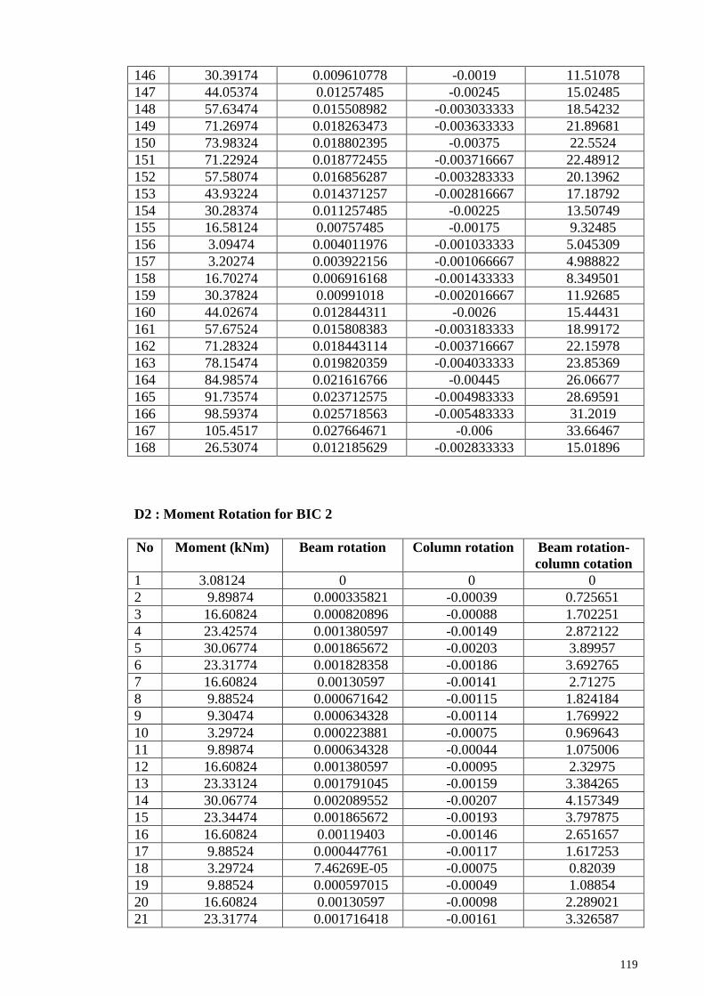
119
146 30.39174 0.009610778 -0.0019 11.51078
147 44.05374 0.01257485 -0.00245 15.02485
148 57.63474 0.015508982 -0.003033333 18.54232
149 71.26974 0.018263473 -0.003633333 21.89681
150 73.98324 0.018802395 -0.00375 22.5524
151 71.22924 0.018772455 -0.003716667 22.48912
152 57.58074 0.016856287 -0.003283333 20.13962
153 43.93224 0.014371257 -0.002816667 17.18792
154 30.28374 0.011257485 -0.00225 13.50749
155 16.58124 0.00757485 -0.00175 9.32485
156 3.09474 0.004011976 -0.001033333 5.045309
157 3.20274 0.003922156 -0.001066667 4.988822
158 16.70274 0.006916168 -0.001433333 8.349501
159 30.37824 0.00991018 -0.002016667 11.92685
160 44.02674 0.012844311 -0.0026 15.44431
161 57.67524 0.015808383 -0.003183333 18.99172
162 71.28324 0.018443114 -0.003716667 22.15978
163 78.15474 0.019820359 -0.004033333 23.85369
164 84.98574 0.021616766 -0.00445 26.06677
165 91.73574 0.023712575 -0.004983333 28.69591
166 98.59374 0.025718563 -0.005483333 31.2019
167 105.4517 0.027664671 -0.006 33.66467
168 26.53074 0.012185629 -0.002833333 15.01896
D2 : Moment Rotation for BIC 2
No Moment (kNm) Beam rotation Column rotation Beam rotation-
column cotation
1 3.08124 0 0 0
2 9.89874 0.000335821 -0.00039 0.725651
3 16.60824 0.000820896 -0.00088 1.702251
4 23.42574 0.001380597 -0.00149 2.872122
5 30.06774 0.001865672 -0.00203 3.89957
6 23.31774 0.001828358 -0.00186 3.692765
7 16.60824 0.00130597 -0.00141 2.71275
8 9.88524 0.000671642 -0.00115 1.824184
9 9.30474 0.000634328 -0.00114 1.769922
10 3.29724 0.000223881 -0.00075 0.969643
11 9.89874 0.000634328 -0.00044 1.075006
12 16.60824 0.001380597 -0.00095 2.32975
13 23.33124 0.001791045 -0.00159 3.384265
14 30.06774 0.002089552 -0.00207 4.157349
15 23.34474 0.001865672 -0.00193 3.797875
16 16.60824 0.00119403 -0.00146 2.651657
17 9.88524 0.000447761 -0.00117 1.617253
18 3.29724 7.46269E-05 -0.00075 0.82039
19 9.88524 0.000597015 -0.00049 1.08854
20 16.60824 0.00130597 -0.00098 2.289021
21 23.31774 0.001716418 -0.00161 3.326587

120
22 30.05424 0.002238806 -0.00207 4.306603
23 23.31774 0.001902985 -0.00193 3.835188
24 16.59474 0.00119403 -0.00146 2.651657
25 9.88524 0.000410448 -0.00114 1.546041
26 3.29724 -0.00011194 -0.00069 0.582975
27 9.88524 0.000447761 -0.00056 1.007083
28 16.62174 0.001044776 -0.00105 2.095624
29 23.34474 0.001529851 -0.00161 3.14002
30 23.33124 0.001567164 -0.00161 3.177334
31 30.05424 0.002201493 -0.00205 4.25234
32 36.79074 0.003395522 -0.00254 5.937895
33 43.51374 0.004253731 -0.00322 7.47407
34 50.23674 0.004813433 -0.00402 8.830382
35 56.95974 0.005559701 -0.00483 10.39021
36 63.68274 0.006865672 -0.00597 12.83177
37 56.94624 0.007537313 -0.0059 13.43562
38 50.22324 0.006977612 -0.00549 12.46914
39 43.50024 0.00630597 -0.00505 11.35682
40 36.77724 0.006007463 -0.00456 10.56678
41 30.04074 0.005373134 -0.00412 9.491778
42 23.31774 0.00511194 -0.00371 8.823805
43 16.59474 0.00391791 -0.0032 7.1213
44 9.87174 0.003395522 -0.00266 6.056539
45 3.27024 0.002313433 -0.00193 4.245636
46 9.88524 0.002947761 -0.00171 4.659626
47 16.60824 0.003768657 -0.00224 6.005945
48 23.33124 0.004402985 -0.00295 7.352138
49 30.05424 0.005074627 -0.00364 8.718695
50 36.77724 0.005858209 -0.0042 10.0616
51 43.50024 0.006567164 -0.00471 11.27903
52 50.22324 0.006977612 -0.00527 12.2488
53 50.22324 0.006940299 -0.00522 12.16064
54 56.95974 0.007425373 -0.0058 13.22198
55 63.68274 0.008358209 -0.00631 14.66329
56 56.94624 0.008059701 -0.00614 14.19529
57 50.19624 0.007574627 -0.00573 13.30344
58 43.48674 0.006716418 -0.00525 11.97066
59 36.76374 0.006343284 -0.00475 11.08905
60 30.05424 0.005559701 -0.00427 9.830888
61 23.31774 0.005223881 -0.00385 9.071338
62 16.59474 0.004477612 -0.00332 7.799646
63 9.87174 0.003097015 -0.00269 5.79193
64 3.28374 0.002276119 -0.002 4.276119
65 9.88524 0.002910448 -0.0018 4.707058
66 16.60824 0.004067164 -0.00234 6.406147
67 23.33124 0.004664179 -0.00297 7.630281
68 30.06774 0.005373134 -0.00373 9.101948
69 36.77724 0.00619403 -0.00429 10.48217
70 43.54074 0.006529851 -0.00486 11.39426
71 50.33124 0.006902985 -0.00546 12.36061

121
72 56.95974 0.007574627 -0.00593 13.50683
73 63.68274 0.008470149 -0.00642 14.89388
74 56.94624 0.008171642 -0.00624 14.40893
75 43.48674 0.00641791 -0.00534 11.75689
76 35.73774 0.005932836 -0.00478 10.7125
77 30.04074 0.005447761 -0.00434 9.786744
78 22.56174 0.005447761 -0.00386 9.312168
79 15.52824 0.004440299 -0.00331 7.745383
80 9.85824 0.003432836 -0.00268 6.110802
81 3.27024 0.002574627 -0.002 4.574627
82 14.71824 0.003768657 -0.00222 5.988996
83 16.60824 0.003992537 -0.00241 6.399317
84 23.52024 0.004664179 -0.00303 7.698077
85 30.05424 0.005373134 -0.00376 9.135846
86 36.77724 0.005858209 -0.00437 10.23109
87 43.51374 0.006119403 -0.00498 11.10245
88 50.22324 0.006716418 -0.00547 12.19099
89 56.95974 0.00738806 -0.006 13.38806
90 63.68274 0.008432836 -0.00647 14.90741
91 70.39224 0.009253731 -0.0071 16.35543
92 82.05624 0.012873134 -0.00871 21.585
93 88.38774 0.01608209 -0.00985 25.92955
94 92.72124 0.018731343 -0.01061 29.34151
95 94.28724 0.021977612 -0.01119 33.16405
96 94.17924 0.025 -0.01147 36.47458
97 95.71824 0.02761194 -0.0118 39.40855
98 96.96024 0.030335821 -0.01212 42.45446
99 97.77024 0.031753731 -0.01241 44.16051
100 97.45974 0.029925373 -0.01264 42.56944
101 98.71524 0.028134328 -0.0128 40.93094
102 97.71624 0.026567164 -0.01293 39.49937
103 57.29724 0.02738806 -0.00988 37.26942
D3 : Moment Rotation for BIC 3
No Moment (kNm) Beam rotation Column rotation Beam rotation-
column cotation
1 3.08124 0 0 0
2 9.81774 0.002985 0 2.985075
3 16.62174 0.003097 -0.00013 3.230348
4 23.22324 0.004104 -0.0006 4.704478
5 29.86524 0.005336 -0.00117 6.502488
6 23.08824 0.005187 -0.00118 6.3699
7 16.37874 0.004328 -0.00118 5.511692
8 9.49374 0.003209 -0.00118 4.392289
9 3.29724 0.002127 -0.00083 2.960199
10 10.00674 0.002239 -0.00083 3.072139
11 16.51374 0.003507 -0.00083 4.340796
12 23.16924 0.004552 -0.00088 5.435572

122
13 29.94624 0.005336 -0.00127 6.602488
14 23.15574 0.004963 -0.00122 6.179353
15 16.44624 0.004142 -0.00122 5.358458
16 9.83124 0.003097 -0.0012 4.297015
17 3.43224 0.001828 -0.00083 2.661692
18 10.04724 0.001978 -0.00085 2.827612
19 16.56774 0.003284 -0.00085 4.133582
20 23.39874 0.004328 -0.0009 5.228358
21 29.82474 0.005037 -0.00123 6.270647
22 23.26374 0.004776 -0.00123 6.009453
23 16.37874 0.003881 -0.00123 5.11393
24 9.91224 0.002873 -0.00122 4.089801
25 3.28374 0.001679 -0.00092 2.595771
26 9.79074 0.001791 -0.00093 2.724378
27 16.55424 0.003134 -0.00093 4.067662
28 23.35824 0.004216 -0.00095 5.166418
29 30.08124 0.004925 -0.00132 6.24204
30 36.65574 0.006007 -0.00185 7.857463
31 43.35174 0.007948 -0.00268 10.63109
32 50.06124 0.010187 -0.00358 13.7699
33 56.78424 0.011716 -0.00445 16.16642
34 63.43974 0.013507 -0.00548 18.9908
35 70.32474 0.016679 -0.00642 23.09577
36 76.99374 0.019925 -0.00757 27.49204
37 69.87924 0.020634 -0.00788 28.51766
38 63.16974 0.019291 -0.00788 27.17438
39 56.47374 0.018507 -0.00762 26.12413
40 49.79124 0.017836 -0.00715 24.98582
41 43.08174 0.017463 -0.00687 24.32935
42 36.34524 0.016679 -0.00665 23.3291
43 29.70324 0.016567 -0.00643 23.0005
44 22.92624 0.015299 -0.00595 21.24851
45 16.37874 0.013358 -0.00545 18.80821
46 9.45324 0.009888 -0.0046 14.48806
47 3.27024 0.00709 -0.00363 10.72289
48 10.08774 0.007239 -0.00363 10.87214
49 16.71624 0.008881 -0.00365 12.5306
50 23.15574 0.009776 -0.00335 13.12612
51 36.85824 0.011007 -0.00447 15.47413
52 43.51374 0.012799 -0.005 17.79851
53 50.27724 0.014739 -0.00557 20.30547
54 56.90574 0.016045 -0.00615 22.19478
55 63.52074 0.017948 -0.00672 24.66443
56 70.13574 0.019216 -0.0074 26.61642
57 76.87224 0.021343 -0.00815 29.49328
58 70.01424 0.021866 -0.00847 30.33234
59 63.45324 0.020784 -0.00845 29.23358
60 56.64924 0.02 -0.0079 27.9
61 49.84524 0.01959 -0.00757 27.15622
62 43.02774 0.018955 -0.00725 26.20522
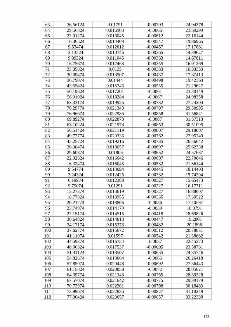
123
63 36.56124 0.01791 -0.00703 24.94378
64 29.56824 0.016903 -0.0066 23.50299
65 22.91274 0.016045 -0.00612 22.16144
66 16.36524 0.014403 -0.00547 19.86965
67 9.57474 0.012612 -0.00457 17.17861
68 3.13524 0.010746 -0.00365 14.39627
69 9.99324 0.011045 -0.00363 14.67811
70 16.75674 0.012463 -0.00355 16.01269
71 23.35824 0.0125 -0.00383 16.33333
72 30.09474 0.013507 -0.00437 17.87413
73 36.79074 0.01444 -0.00498 19.42363
74 43.55424 0.015746 -0.00555 21.29627
75 50.19624 0.017201 -0.0061 23.30149
76 56.91924 0.018284 -0.0067 24.98358
77 63.33174 0.019925 -0.00732 27.24204
78 70.29774 0.021343 -0.00797 29.30995
79 76.96674 0.022985 -0.00858 31.56841
80 69.89274 0.022873 -0.0087 31.57313
81 63.10224 0.021978 -0.00853 30.51095
82 56.51424 0.021119 -0.00807 29.18607
83 49.77774 0.020336 -0.00762 27.95249
84 43.25724 0.019216 -0.00735 26.56642
85 36.30474 0.018657 -0.00697 25.62338
86 29.60874 0.01806 -0.00652 24.57637
87 22.92624 0.016642 -0.00607 22.70846
88 16.32474 0.016045 -0.00532 21.36144
89 9.54774 0.013694 -0.00445 18.14403
90 3.24324 0.012425 -0.00332 15.74204
91 6.19974 0.012388 -0.00327 15.65473
92 9.79074 0.01291 -0.00327 16.17711
93 13.27374 0.013619 -0.00327 16.88607
94 16.77024 0.013955 -0.00335 17.30522
95 20.21274 0.013806 -0.0036 17.40597
96 23.74974 0.014179 -0.0039 18.0791
97 27.15174 0.014515 -0.00418 18.69826
98 30.64824 0.014813 -0.00447 19.2801
99 34.17174 0.015373 -0.00482 20.1898
100 37.62774 0.015672 -0.00512 20.78831
101 41.11074 0.01597 -0.00542 21.38682
102 44.59374 0.016754 -0.0057 22.45373
103 48.06324 0.017537 -0.00605 23.58731
104 51.41124 0.018507 -0.00635 24.85746
105 54.82674 0.019664 -0.0066 26.26418
106 57.85074 0.020448 -0.00692 27.36443
107 61.15824 0.020858 -0.0072 28.05821
108 64.35774 0.021343 -0.00755 28.89328
109 67.57074 0.021642 -0.00775 29.39179
110 70.72974 0.022201 -0.00798 30.18483
111 73.99674 0.022836 -0.00827 31.10249
112 77.30424 0.023657 -0.00857 32.22338

124
113 80.47674 0.024851 -0.00895 33.80075
114 6.06474 0.063843 -0.00435 68.19328

125
Appendix E : Data for Load Displacement Graph
E1 : Load Displacement for BIC 1 (Cycle 3)
No Load (kN) Displacement (LVDT 6)(mm)
1 0 0
2 0.08 -0.09
3 10.08 0.02
4 20.21 0.26
5 30.32 0.35
6 40.43 0.35
7 50.51 0.36
8 55.6 0.44
9 60.66 10.03
10 65.66 21.3
11 70.74 30.9
12 75.82 30.9
13 17.36 30.97
E2 : Load Displacement for BIC 2 (Cycle 3)
No Load (kN) Displacement (LVDT 6)(mm)
1 0 0
2 8.48 -0.16
3 9.88 -0.14
4 15 0.15
5 19.84 0.52
6 24.82 0.82
7 29.81 1.09
8 34.78 1.34
9 39.77 1.62
10 44.75 1.9
11 49.72 2.23
12 58.36 3.15
13 63.05 3.88
14 66.26 4.52
15 67.42 5.18
16 67.34 5.73
17 68.48 6.37
18 69.4 7.01
19 70 7.58
20 69.77 8.07
21 70.7 8.55
22 69.96 8.97
23 40.02 8.75

126
E3 : Load Displacement for BIC 3 (Cycle 3)
No Load (kN) Displacement (LVDT 6)(mm)
1 0 0
2 2.2 -0.03
3 4.86 -0.03
4 7.44 0.22
5 10.03 0.51
6 12.58 0.83
7 15.2 1.03
8 17.72 1.23
9 20.31 1.45
10 22.92 1.6
11 25.48 1.78
12 28.06 1.98
13 30.64 2.06
14 33.21 2.1
15 35.69 2.16
16 38.22 2.21
17 40.46 2.22
18 42.91 2.33
19 45.28 2.61
20 47.66 2.66
21 50 2.78
22 52.42 2.94
23 54.87 3.1
24 57.22 3.21

127
Appendix F : Data for Load Strain Graph
F1 : Load Strain for BIC 1
No Load (kN)
Strain gauge 5 (S5)
(x10-6)
Strain gauge 6 (S6)
(x10-6)
1 0 0 0
2 1.99 10 5
3 4.06 17 7
4 6.1 23 6
5 8.15 29 10
6 10.18 35 12
7 12.22 42 15
8 14.26 46 14
9 16.31 52 14
10 18.34 66 21
11 20.39 76 23
12 18.34 83 29
13 16.3 74 27
14 14.26 67 23
15 12.2 59 19
16 10.17 50 16
17 8.12 46 17
18 6.08 43 18
19 4.05 36 18
20 1.99 34 21
21 0.02 27 18
22 2.02 37 25
23 4.06 45 28
24 6.09 48 27
25 8.16 56 29
26 10.19 62 29
27 12.24 70 32
28 14.26 76 36
29 16.3 83 37
30 18.35 90 40
31 20.4 93 37
32 18.34 91 38
33 16.29 88 38
34 14.26 95 49
35 12.21 79 38
36 10.14 81 44
37 8.11 72 41
38 6.01 66 38
39 4.07 65 44
40 1.99 56 41
41 0 44 34
42 2.03 47 33
43 4.1 54 35
44 6.15 59 35

128
45 8.15 64 36
46 10.21 81 46
47 12.28 83 45
48 14.3 92 49
49 16.36 95 48
50 18.36 114 59
51 20.4 118 59
52 18.34 111 54
53 16.3 101 49
54 14.26 104 54
55 12.18 97 54
56 10.17 100 61
57 8.11 93 62
58 6.05 82 53
59 6.11 91 63
60 4.02 84 62
61 2.03 73 56
62 0.11 74 62
63 0.09 79 66
64 5.09 91 68
65 10.23 108 71
66 15.31 119 71
67 20.42 136 75
68 22.45 143 75
69 24.49 157 79
70 26.52 168 75
71 28.59 187 79
72 30.64 210 83
73 32.64 266 90
74 34.7 294 92
75 36.75 328 95
76 38.78 381 112
77 40.87 423 121
78 42.92 495 136
79 44.88 553 142
80 46.93 616 147
81 48.98 679 163
82 51.01 790 172
83 53.03 803 168
84 50.49 802 177
85 48.46 782 178
86 46.43 753 167
87 44.42 725 161
88 42.43 715 169
89 40.4 696 169
90 38.36 678 167
91 36.35 649 162
92 34.34 612 147
93 32.3 587 142
94 30.3 572 146

129
95 28.26 551 144
96 26.24 524 138
97 24.23 512 144
98 22.22 486 139
99 20.17 456 129
100 18.14 443 136
101 15.12 401 128
102 10.01 330 117
103 5.01 267 119
104 0.05 184 104
105 5.09 204 112
106 10.22 249 120
107 15.16 314 131
108 20.21 379 142
109 22.23 405 147
110 24.28 432 156
111 26.27 448 155
112 28.32 473 162
113 30.35 490 162
114 32.39 502 160
115 34.37 525 168
116 36.39 548 175
117 38.43 564 177
118 40.45 580 177
119 42.48 598 180
120 44.51 618 184
121 46.48 640 188
122 48.54 661 190
123 50.56 685 191
124 52.58 715 195
125 50.48 717 199
126 48.44 698 193
127 46.45 677 183
128 44.44 669 190
129 42.39 655 191
130 40.38 628 182
131 38.35 608 178
132 36.34 588 177
133 34.32 565 169
134 32.28 537 160
135 30.26 522 163
136 28.25 503 162
137 26.22 474 156
138 24.2 454 156
139 22.17 432 155
140 20.14 405 148
141 15.09 335 136
142 10.05 268 131
143 4.96 188 119
144 0.05 127 117

130
145 10.11 206 133
146 20.23 356 164
147 30.35 471 180
148 40.41 579 199
149 50.51 681 213
150 52.52 706 217
151 50.48 704 220
152 40.37 623 206
153 30.26 512 185
154 20.15 396 168
155 10 249 144
156 0.01 108 126
157 0.09 115 132
158 10.09 204 152
159 20.22 345 175
160 30.33 473 195
161 40.44 583 209
162 50.52 699 235
163 55.61 775 254
164 60.67 885 266
165 65.67 1059 278
166 70.75 1297 298
167 75.83 1574 339
168 17.37
F2 : Load Strain for BIC 2
No Load (kN)
Strain gauge 5 (S5)
(x10-6)
Strain gauge 6 (S6)
(x10-6)
1 0 0 0
2 5.05 10 11
3 10.02 23 26
4 15.07 48 52
5 19.99 62 69
6 14.99 57 64
7 10.02 38 46
8 5.04 28 37
9 4.61 30 40
10 0.16 18 26
11 5.05 32 40
12 10.02 37 46
13 15 62 71
14 19.99 70 80
15 15.01 66 75
16 10.02 54 63
17 5.04 40 53
18 0.16 23 35
19 5.04 44 56

131
20 10.02 52 63
21 14.99 64 75
22 19.98 86 99
23 14.99 70 82
24 10.01 52 63
25 5.04 44 57
26 0.16 27 41
27 5.04 32 44
28 10.03 46 59
29 15.01 63 77
30 15 63 77
31 19.98 80 94
32 24.97 94 108
33 29.95 117 138
34 34.93 148 174
35 39.91 191 233
36 44.89 243 308
37 39.9 243 319
38 34.92 229 304
39 29.94 224 298
40 24.96 216 289
41 19.97 193 265
42 14.99 174 243
43 10.01 148 213
44 5.03 140 202
45 0.14 108 169
46 5.04 120 182
47 10.02 145 209
48 15 154 221
49 19.98 180 246
50 24.96 199 268
51 29.94 214 288
52 34.92 226 300
53 34.92 227 300
54 39.91 258 338
55 44.89 282 369
56 39.9 272 366
57 34.9 261 355
58 29.93 236 327
59 24.95 225 317
60 19.98 206 296
61 14.99 186 275
62 10.01 166 251
63 5.03 143 224
64 0.15 119 200
65 5.04 130 208
66 10.02 145 226
67 15 169 252
68 19.99 186 273
69 24.96 208 298

132
70 29.97 229 321
71 35 263 358
72 39.91 285 384
73 44.89 319 423
74 39.9 315 419
75 29.93 277 379
76 24.19 250 350
77 19.97 234 334
78 14.43 217 317
79 9.22 180 273
80 5.02 152 243
81 0.14 144 233
82 8.62 166 256
83 10.02 170 261
84 15.14 198 292
85 19.98 218 318
86 24.96 229 326
87 29.95 253 355
88 34.92 286 390
89 39.91 304 412
90 44.89 341 451
91 49.86 405 519
92 58.5 939 1072
93 63.19 1244 1332
94 66.4 1516 1547
95 67.56 1684 1666
96 67.48 1770 1732
97 68.62 1859 1784
98 69.54 1955 1848
99 70.14 1986 1892
100 69.91 2037 1928
101 70.84 2085 1981
102 70.1 2114 2017
103 40.16 519 1786
F3 : Load Strain for BIC 3
No Load (kN)
Strain gauge 5 (S5)
(x10-6)
Strain gauge 6 (S6)
(x10-6)
1 0 0 0
2 4.99 -18 -16
3 10.03 -34 -32
4 14.92 -45 -46
5 19.84 -60 -64
6 14.82 -43 -50
7 9.85 -29 -39
8 4.75 -23 -32
9 0.16 -2 -7

133
10 5.13 -10 -16
11 9.95 -21 -28
12 14.88 -45 -47
13 19.9 -53 -54
14 14.87 -35 -39
15 9.9 -23 -30
16 5 -2 -10
17 0.26 1 0
18 5.16 -5 -9
19 9.99 -13 -17
20 15.05 -29 -31
21 19.81 -44 -44
22 14.95 -26 -30
23 9.85 -6 -14
24 5.06 6 0
25 0.15 17 15
26 0.11 19 18
27 4.97 15 11
28 9.98 1 -3
29 15.02 -12 -15
30 20 -23 -23
31 24.87 -34 -35
32 29.83 -50 -54
33 34.8 -61 -71
34 39.78 -68 -86
35 44.71 -76 -103
36 49.81 -90 -131
37 54.75 -92 -150
38 49.48 -77 -144
39 44.51 -60 -129
40 39.55 -43 -115
41 34.6 -25 -97
42 29.63 -5 -76
43 24.64 6 -64
44 19.72 21 -46
45 14.7 30 -30
46 9.85 36 -8
47 4.72 43 10
48 0.14 44 24
49 5.19 38 10
50 10.1 33 -2
51 14.87 25 -21
52 25.02 -2 -58
53 29.95 -15 -75
54 34.96 -32 -92
55 39.87 -54 -112
56 44.77 -67 -127
57 49.67 -86 -148
58 54.66 -95 -163
59 49.58 -86 -158

134
60 44.72 -67 -143
61 39.68 -54 -131
62 34.64 -28 -107
63 29.59 -12 -91
64 24.8 1 -74
65 19.62 16 -55
66 14.69 26 -38
67 9.84 31 -23
68 4.81 37 -3
69 0.04 46 16
70 5.12 42 3
71 10.13 34 -12
72 15.02 30 -23
73 20.01 17 -43
74 24.97 4 -60
75 29.98 -9 -76
76 34.9 -24 -92
77 39.88 -38 -107
78 44.63 -57 -126
79 49.79 -71 -141
80 54.73 -87 -159
81 49.49 -66 -145
82 44.46 -47 -127
83 39.58 -30 -111
84 34.59 -15 -96
85 29.76 0 -80
86 24.61 15 -62
87 19.65 28 -46
88 14.7 31 -33
89 9.81 39 -15
90 4.79 46 5
91 -0.13 49 22
92 0.12 47 21
93 0.11 54 28
94 2.31 54 23
95 4.97 49 13
96 7.55 48 6
97 10.14 45 -1
98 12.69 41 -12
99 15.31 34 -21
100 17.83 30 -29
101 20.42 27 -35
102 23.03 22 -42
103 25.59 15 -52
104 28.17 1 -65
105 30.75 -6 -76
106 33.32 -15 -87
107 35.8 -24 -94
108 38.33 -29 -100
109 40.57 -39 -111

135
110 43.02 -47 -120
111 45.39 -54 -129
112 47.77 -60 -134
113 50.11 -67 -141
114 52.53 -76 -151
115 54.98 -80 -156
116 57.33 -86 -168
117 2.21 -13
118 40.45 580 177
119 42.48 598 180
120 44.51 618 184
121 46.48 640 188
122 48.54 661 190
123 50.56 685 191
124 52.58 715 195
125 50.48 717 199
126 48.44 698 193
127 46.45 677 183
128 44.44 669 190
129 42.39 655 191
130 40.38 628 182
131 38.35 608 178
132 36.34 588 177
133 34.32 565 169
134 32.28 537 160
135 30.26 522 163
136 28.25 503 162
137 26.22 474 156
138 24.2 454 156
139 22.17 432 155
140 20.14 405 148
141 15.09 335 136
142 10.05 268 131
143 4.96 188 119
144 0.05 127 117
145 10.11 206 133
146 20.23 356 164
147 30.35 471 180
148 40.41 579 199
149 50.51 681 213
150 52.52 706 217
151 50.48 704 220
152 40.37 623 206
153 30.26 512 185
154 20.15 396 168
155 10 249 144
156 0.01 108 126
157 0.09 115 132
158 10.09 204 152
159 20.22 345 175

136
160 30.33 473 195
161 40.44 583 209
162 50.52 699 235
163 55.61 775 254
164 60.67 885 266
165 65.67 1059 278
166 70.75 1297 298
167 75.83 1574 339