Full Scale Post Test Report - Allan Block
43
Full Scale Post Test Report
Transcript of Full Scale Post Test Report - Allan Block

Full Scale Post Test Report


Allan Block AB Fence Testing
8.6’ Full Scale Post Test Report
July 25, 2006


Introduction This report gives the results for the full-scale tests on two Allan Block Fence posts. The same posts were used in both the Vertical Spreader Bar panel tests and the 12x7 Articulating Spreader Frame tests preformed on the Allan Block Fence panel. All tests were preformed in the Allan Block lab using Allan Block equipment and personnel along with a representative from Stork Twin City Testing (STCT) witnessing and certifying the testing procedures and results. These tests were preformed in September 2005 and are an extension of the Fence Testing preformed at the University of Calgary in 2003 and the Allan Block AB Fence Testing preformed on the panel assembly in August 2004. Objectives of Test Program The principle objective of this test is to determine the actual capacity of the Allan Block Fence Post in an on-site (cantilever) configuration. The resulting data will be used to further understand the capacities of the system and to produce a more accurate design methodology for the Allan Block segmental fence system. The Moment capacity of the Allan Block post will be determined by recording the applied force from the hydraulic ram, which is fixed at a specific point above the foundation. The position of the ram above the floor is the fixed moment arm and when multiplied by the applied load the moment capacity is determined. The realized post moment capacity can than be compared to a calculated capacity using accepted beam theory equations, See Appendix C for hand calculations. If the system capacity is higher or lower than the calculated values, the AB Fence design methodology can be adjusted to better fit the segmental nature of the Allan Block Fence Post. Careful attention will be given to the recording of deflections and rebounds to document the potential plasticity of the post system.
Test Procedure and Results The tested posts were previously used in the Vertical Spreader Bar panel tests and the 12x7 Articulating Spreader Frame tests. When the Panel tests were completed, the two posts were left in place after panel demolition to proceed with these cantilever moment capacity tests. The construction of the post was preformed exactly as would be under field conditions. Each post consisted of 13 courses of standard post block with 4 - #5 footing dowels extending 24 inches into the post, spliced with 4 - #5 vertical post bars. As is typical for field construction, the lap splices were not tied. The hollow core of each post was filled with a bag mix concrete which tested out at an average of 4650 psi ( 32.0 MPa). A 25 ton (111.2 kN) hydraulic ram was fixed at 6ft above the lab floor and a 10,000 pound (44.5 kN) load cell was placed to record the applied
Figure 1: Post 1 Test Frame Set-up
Figure 2: In Place Load Cell and Deflection Transducer
1 of 3

4 - # 5 POST REBAR
P
6'-0"
4 - # 5 FOOTING DOWELS
SUBJECT AREA "A"Mcp (ten) = 22,643 lb*ftMcp (comp) = 42,851 lb*ft
SUBJECT AREA "B"Mcp (ten) = 43,895 lb*ftMcp (comp) = 55,321 lb*ft
SUBJECT AREA "C"Mcp (ten) = 22,643 lb*ftMcp (comp) = 42,851 lb*ft
NOTE:SUBJECT AREA "A" = CRITICAL SECTION = THE AREA BETWEEN FOOTING AND THE REBAR SPLICE
SUBJECT AREA "B" = THE AREA WITHIN THE REBAR SPLICE
SUBJECT AREA "C" = THE AREA ABOVE REBAR SPLICE
CALCULATED MOMENT CAPACITIES
load, see Figures 1 and 2. Post One was stressed and rebounded 8 times and Post Two 9 times, with the last of each to failure. See Appendix B for the actual test data. The recorded deflection data was remarkably similar for each load application, reflecting the fact that during each stressing and subsequent rebound, the composite post did not yield in any way and remained entirely plastic by nature until the final failure stressing. Appendix C contains a set of hand calculation using no material reduction for steel or concrete strengths or any reductions for exposure. These were computed to determine a maximum expected failure moment. The calculations show the maximum moment expected for both a compressive and a tensile failure. The calculated tensile failure was nearly half that of the compressive failure. This is due to the small steel to concrete ratio. Therefore, the expected failure mode was tensile, but the ultimate failures for both posts appeared to be in compression of concrete. Figure 3 shows the failure location and resulting shear crack at the top of splice location. The ultimate moment for both posts resulted in a moment that nearly matched the calculated compressive failure exactly. This warranted a closer evaluation of the calculated moments in the base of the post. Figure 4 shows a break down of calculated moments in the three locations in and around the splice. Failure occurred in Subject Area C and not in the expected location of Subject Area A. See Appendix C for hand calculations expressing the calculated moment capacities under the failure load. The tested ultimate failure and ultimate capacity moments at Area C again matched closely. Therefore the ultimate failure appears to be a yielding of the tensile rebar at Area C which then allowed the compressive capacity to be overcome resulting in the shear crack and the inability of the post to rebound after the load was removed.
Figure 3: Post 1 after failure
Top of Splice
Figure 4: Calculated Test Moment in Splice location
2 of 3

But why did the failure not occur in Subject Area A where that failure moment is greater? Figure 5 show a typical footing dowel. The lower half is embedded into the lab floor and the threaded end can be inserted and removed. These inserts are designed to be at least 125% stronger than the actual rebar itself. The threaded insert is directly located in Area A. This insert changed the capacity moments in Area A enough to force the actual failure to occur in the next weakest area – Area C. Figure 6 shows the same location after the face shell has been removed. A jack hammer was required to remove the Allan Block face because of the extraordinary bonding which occurred during the curing process. Conclusions and Recommendations These two posts tested so close to the calculated capacities using first principle beam capacity equations that there can be no recommendation to change the way the capacities are currently calculated. Additionally, it is concluded that in a field operation with continuous footing dowels the maximum moment would occur at the base and not above the splice. This matches the current design methodology. The capacity realized in these tests would be sufficient to support a panel 11’-2” in height x 33’-5” in Length ( 3.4m x 10.24m ) with a sustained wind load of 100 mph, or 19.2 psf ( 160.93 Kph, or 0.92 kPa ), allowing a safety factor of 1.0 with no material strength reductions, see Figure 7. The following are a list of conclusions formulated from physical data and visual observation during testing:
• Both Posts preformed as expected and matched calculated capacities nearly exactly.
• The composite nature of the Allan Block Post clearly performs as a monolithic cantilever beam, proving the post block can be used as part of the design section.
• The dismantling of the post showed fully encapsulated rebar with adequate concrete cover. • The non-tied rebar splice clearly provided excess capacity proving that tying is not required.
3 of 3 Figure 7: Projected Maximum Panel size for tested Post
Figure 6: Post 1 Splice after dismantling
Tensile side
Compressive Side
Figure 5: Footing Dowel Insert
Tensile side
Compressive Side


APPENDIX A
Test Frame and Equipment

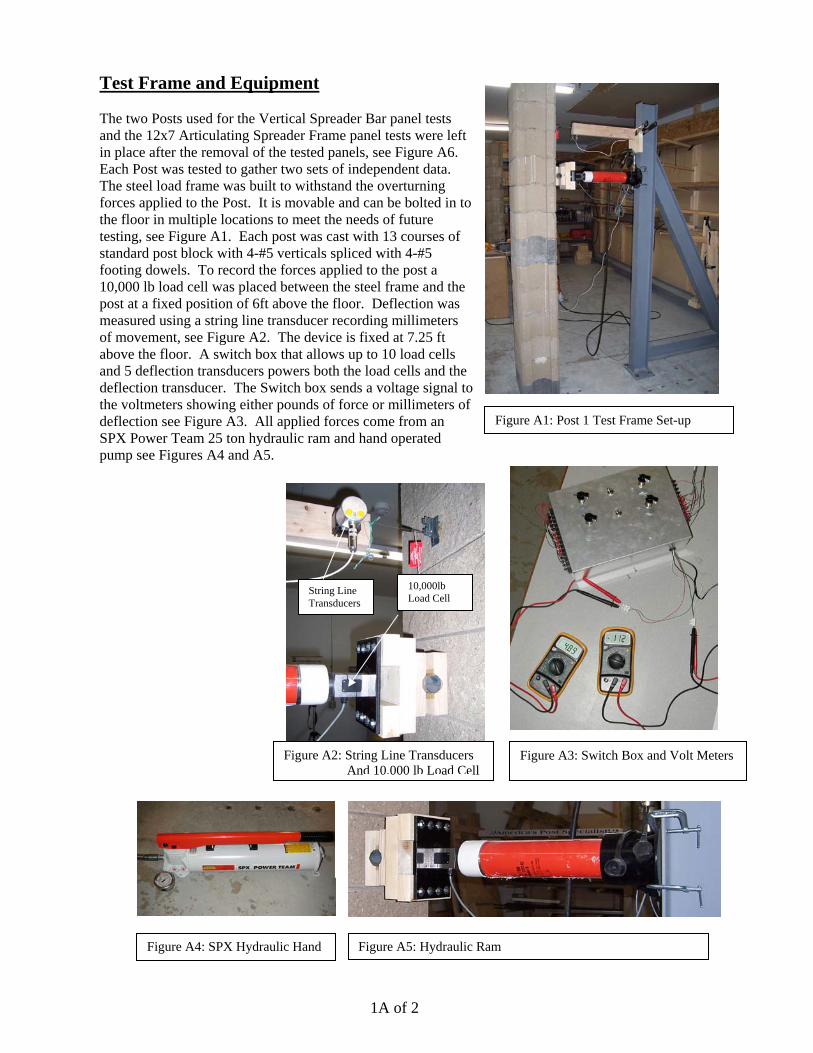
Figure A4: SPX Hydraulic Hand
Figure A3: Switch Box and Volt Meters
Test Frame and Equipment The two Posts used for the Vertical Spreader Bar panel tests and the 12x7 Articulating Spreader Frame panel tests were left in place after the removal of the tested panels, see Figure A6. Each Post was tested to gather two sets of independent data. The steel load frame was built to withstand the overturning forces applied to the Post. It is movable and can be bolted in to the floor in multiple locations to meet the needs of future testing, see Figure A1. Each post was cast with 13 courses of standard post block with 4-#5 verticals spliced with 4-#5 footing dowels. To record the forces applied to the post a 10,000 lb load cell was placed between the steel frame and the post at a fixed position of 6ft above the floor. Deflection was measured using a string line transducer recording millimeters of movement, see Figure A2. The device is fixed at 7.25 ft above the floor. A switch box that allows up to 10 load cells and 5 deflection transducers powers both the load cells and the deflection transducer. The Switch box sends a voltage signal to the voltmeters showing either pounds of force or millimeters of deflection see Figure A3. All applied forces come from an SPX Power Team 25 ton hydraulic ram and hand operated pump see Figures A4 and A5.
Figure A5: Hydraulic Ram
String Line Transducers
Figure A2: String Line Transducers And 10,000 lb Load Cell
1A of 2
10,000lb Load Cell
Figure A1: Post 1 Test Frame Set-up

Figure A6: Full-Scale Panel Set-up showing Post 1 and 2
TEST POST 2 TEST POST 1
2A of 2

APPENDIX B
Test Result Data


POST 1


POST
1M
omen
t ver
ses
Def
lect
ion
Engl
ish
Uni
ts
0.00
0.50
1.00
1.50
2.00
2.50
3.00
3.50
4.00 1191
.66
4766
.64
8341
.62
1191
6.6
1549
1.6
1906
6.6
2264
1.5
2621
6.5
2979
1.5
3336
6.5
3694
1.5
4051
6.4
Mom
ent (
ft-lb
s)
Deflection (in)
Ser
ies1
Ser
ies2
Ser
ies3
Ser
ies4
Ser
ies5
Ser
ies6
Ser
ies7
Ser
ies8

POST
1M
omen
t ver
ses
Def
lect
ion
Met
ric U
nits
0.0
10.0
20.0
30.0
40.0
50.0
60.0
70.0
80.0
90.0
100.
0
1615
.68
6462
.71
1130
9.74 16
156.7
6 2100
3.79 25
850.8
2 3069
7.85 35
544.8
8 4039
1.91 45
238.9
4 5008
5.97 54
933.0
0
Mom
ent (
N-m
)
Deflection (mm)
Ser
ies1
Ser
ies2
Ser
ies3
Ser
ies4
Ser
ies5
Ser
ies6
Ser
ies7
Ser
ies8

POST
1 D
ATA
Ram
Pos
ition
Abo
ve F
loor
Mom
ent A
rm -
ft (m
) =5.
958
(1.8
16)
Serie
s 1
poun
ds fo
rce
- lb
=20
040
060
080
010
0012
0014
0016
0018
0020
0022
0024
0026
0028
00po
unds
forc
e (N
) =(8
89.6
4)(1
779.
28)
(266
8.92
)(3
558.
56)
(444
8.20
)(5
337.
84)
(622
7.48
)(7
117.
12)
(800
6.76
)(8
896.
40)
(978
6.04
)(1
0675
.68)
(115
65.3
2)(1
2454
.96)
Mom
ent -
lb*f
t =11
91.6
623
83.3
235
74.9
847
66.6
459
58.3
7149
.96
8341
.62
9533
.28
1072
4.94
1191
6.6
1310
8.26
1429
9.92
1549
1.58
1668
3.24
Mom
ent (
N*m
) =(1
615.
68)
(323
1.35
)(4
847.
03)
(646
2.71
)(8
078.
38)
(969
4.06
)(1
1309
.74)
(129
25.4
1)(1
4541
.09)
(161
56.7
6)(1
7772
.44)
(193
88.1
2)(2
1003
.79)
(226
19.4
7)
Def
lect
ion
Rea
ding
- in
=
0.07
90.
118
0.15
70.
197
0.19
70.
236
0.27
60.
315
0.35
40.
394
0.43
30.
472
0.51
20.
551
Def
lect
ion
Rea
ding
(mm
) =
(2.0
)(3
.0)
(4.0
)(5
.0)
(5.0
)(6
.0)
(7.0
)(8
.0)
(9.0
)(1
0.0)
(11.
0)(1
2.0)
(13.
0)(1
4.0)
Sto
p
Serie
s 2
poun
ds fo
rce
- lb
=20
040
060
080
010
0012
0014
0016
0018
0020
0022
0024
0026
0028
0030
0032
0034
0036
00po
unds
forc
e (N
) =(8
89.6
4)(1
779.
28)
(266
8.92
)(3
558.
56)
(444
8.20
)(5
337.
84)
(622
7.48
)(7
117.
12)
(800
6.76
)(8
896.
40)
(978
6.04
)(1
0675
.68)
(115
65.3
2)(1
2454
.96)
(133
44.6
0)(1
4234
.24)
(151
23.8
8)(1
6013
.52)
Mom
ent -
lb*f
t =11
91.6
623
83.3
235
74.9
847
66.6
459
58.3
7149
.96
8341
.62
9533
.28
1072
4.94
1191
6.6
1310
8.26
1429
9.92
1549
1.58
1668
3.24
1787
4.9
1906
6.56
2025
8.22
2144
9.88
Mom
ent (
N*m
) =(1
615.
68)
(323
1.35
)(4
847.
03)
(646
2.71
)(8
078.
38)
(969
4.06
)(1
1309
.74)
(129
25.4
1)(1
4541
.09)
(161
56.7
6)(1
7772
.44)
(193
88.1
2)(2
1003
.79)
(226
19.4
7)(2
4235
.15)
(258
50.8
2)(2
7466
.50)
(290
82.1
8)
Def
lect
ion
Rea
ding
- in
=
0.07
90.
118
0.15
70.
197
0.23
60.
276
0.27
60.
315
0.35
40.
394
0.43
30.
472
0.51
20.
551
0.59
10.
630
0.74
80.
787
Def
lect
ion
Rea
ding
(mm
) =
(2.0
)(3
.0)
(4.0
)(5
.0)
(6.0
)(7
.0)
(7.0
)(8
.0)
(9.0
)(1
0.0)
(11.
0)(1
2.0)
(13.
0)(1
4.0)
(15.
0)(1
6.0)
(19.
0)(2
0.0)
stop
Serie
s 3
poun
ds fo
rce
- lb
=20
040
060
080
010
0012
0014
0016
0018
0020
0022
0024
0026
0028
0030
0032
0034
0036
00po
unds
forc
e (N
) =(8
89.6
4)(1
779.
28)
(266
8.92
)(3
558.
56)
(444
8.20
)(5
337.
84)
(622
7.48
)(7
117.
12)
(800
6.76
)(8
896.
40)
(978
6.04
)(1
0675
.68)
(115
65.3
2)(1
2454
.96)
(133
44.6
0)(1
4234
.24)
(151
23.8
8)(1
6013
.52)
Mom
ent -
lb*f
t =11
91.6
623
83.3
235
74.9
847
66.6
459
58.3
7149
.96
8341
.62
9533
.28
1072
4.94
1191
6.6
1310
8.26
1429
9.92
1549
1.58
1668
3.24
1787
4.9
1906
6.56
2025
8.22
2144
9.88
Mom
ent (
N*m
) =(1
615.
68)
(323
1.35
)(4
847.
03)
(646
2.71
)(8
078.
38)
(969
4.06
)(1
1309
.74)
(129
25.4
1)(1
4541
.09)
(161
56.7
6)(1
7772
.44)
(193
88.1
2)(2
1003
.79)
(226
19.4
7)(2
4235
.15)
(258
50.8
2)(2
7466
.50)
(290
82.1
8)
Def
lect
ion
Rea
ding
- in
=
0.07
90.
118
0.15
70.
197
0.23
60.
276
0.35
40.
394
0.43
30.
472
0.51
20.
551
0.59
10.
630
0.66
90.
709
0.74
80.
787
Def
lect
ion
Rea
ding
(mm
) =
(2.0
)(3
.0)
(4.0
)(5
.0)
(6.0
)(7
.0)
(9.0
)(1
0.0)
(11.
0)(1
2.0)
(13.
0)(1
4.0)
(15.
0)(1
6.0)
(17.
0)(1
8.0)
(19.
0)(2
0.0)
stop
Serie
s 4
poun
ds fo
rce
- lb
=20
040
060
080
010
0012
0014
0016
0018
0020
0022
0024
0026
0028
0030
0032
0034
0036
0038
0040
0042
0044
00po
unds
forc
e (N
) =(8
89.6
4)(1
779.
28)
(266
8.92
)(3
558.
56)
(444
8.20
)(5
337.
84)
(622
7.48
)(7
117.
12)
(800
6.76
)(8
896.
40)
(978
6.04
)(1
0675
.68)
(115
65.3
2)(1
2454
.96)
(133
44.6
0)(1
4234
.24)
(151
23.8
8)(1
6013
.52)
(169
03.1
6)(1
7792
.80)
(186
82.4
4)(1
9572
.08)
Mom
ent -
lb*f
t =11
91.6
623
83.3
235
74.9
847
66.6
459
58.3
7149
.96
8341
.62
9533
.28
1072
4.94
1191
6.6
1310
8.26
1429
9.92
1549
1.58
1668
3.24
1787
4.9
1906
6.56
2025
8.22
2144
9.88
2264
1.54
2383
3.2
2502
4.86
2621
6.52
Mom
ent (
N*m
) =(1
615.
68)
(323
1.35
)(4
847.
03)
(646
2.71
)(8
078.
38)
(969
4.06
)(1
1309
.74)
(129
25.4
1)(1
4541
.09)
(161
56.7
6)(1
7772
.44)
(193
88.1
2)(2
1003
.79)
(226
19.4
7)(2
4235
.15)
(258
50.8
2)(2
7466
.50)
(290
82.1
8)(3
0697
.85)
(323
13.5
3)(3
3929
.21)
(355
44.8
8)
Def
lect
ion
Rea
ding
- in
=
0.07
90.
118
0.15
70.
236
0.27
60.
315
0.35
40.
394
0.43
30.
472
0.51
20.
551
0.59
10.
630
0.66
90.
709
0.74
80.
787
0.86
60.
945
1.02
41.
142
Def
lect
ion
Rea
ding
(mm
) =
(2.0
)(3
.0)
(4.0
)(6
.0)
(7.0
)(8
.0)
(9.0
)(1
0.0)
(11.
0)(1
2.0)
(13.
0)(1
4.0)
(15.
0)(1
6.0)
(17.
0)(1
8.0)
(19.
0)(2
0.0)
(22.
0)(2
4.0)
(26.
0)(2
9.0)
stop
Serie
s 5
poun
ds fo
rce
- lb
=20
040
060
080
010
0012
0014
0016
0018
0020
0022
0024
0026
0028
0030
0032
0034
0036
0038
0040
0042
0044
0046
0048
00po
unds
forc
e (N
) =(8
89.6
4)(1
779.
28)
(266
8.92
)(3
558.
56)
(444
8.20
)(5
337.
84)
(622
7.48
)(7
117.
12)
(800
6.76
)(8
896.
40)
(978
6.04
)(1
0675
.68)
(115
65.3
2)(1
2454
.96)
(133
44.6
0)(1
4234
.24)
(151
23.8
8)(1
6013
.52)
(169
03.1
6)(1
7792
.80)
(186
82.4
4)(1
9572
.08)
(204
61.7
2)(2
1351
.36)
Mom
ent -
lb*f
t =11
91.6
623
83.3
235
74.9
847
66.6
459
58.3
7149
.96
8341
.62
9533
.28
1072
4.94
1191
6.6
1310
8.26
1429
9.92
1549
1.58
1668
3.24
1787
4.9
1906
6.56
2025
8.22
2144
9.88
2264
1.54
2383
3.2
2502
4.86
2621
6.52
2740
8.18
2859
9.84
Mom
ent (
N*m
) =(1
615.
68)
(323
1.35
)(4
847.
03)
(646
2.71
)(8
078.
38)
(969
4.06
)(1
1309
.74)
(129
25.4
1)(1
4541
.09)
(161
56.7
6)(1
7772
.44)
(193
88.1
2)(2
1003
.79)
(226
19.4
7)(2
4235
.15)
(258
50.8
2)(2
7466
.50)
(290
82.1
8)(3
0697
.85)
(323
13.5
3)(3
3929
.21)
(355
44.8
8)(3
7160
.56)
(387
76.2
4)
Def
lect
ion
Rea
ding
- in
=
0.07
90.
157
0.19
70.
236
0.27
60.
315
0.39
40.
394
0.47
20.
512
0.55
10.
591
0.63
00.
709
0.74
80.
787
0.82
70.
866
0.90
60.
945
1.02
41.
063
1.18
11.
299
Def
lect
ion
Rea
ding
(mm
) =
(2.0
)(4
.0)
(5.0
)(6
.0)
(7.0
)(8
.0)
(10.
0)(1
0.0)
(12.
0)(1
3.0)
(14.
0)(1
5.0)
(16.
0)(1
8.0)
(19.
0)(2
0.0)
(21.
0)(2
2.0)
(23.
0)(2
4.0)
(26.
0)(2
7.0)
(30.
0)(3
3.0)
stop
Serie
s 6
poun
ds fo
rce
- lb
=20
040
060
080
010
0012
0014
0016
0018
0020
0022
0024
0026
0028
0030
0032
0034
0036
0038
0040
0042
0044
0046
0048
0050
0052
0054
0056
00po
unds
forc
e (N
) =(8
89.6
4)(1
779.
28)
(266
8.92
)(3
558.
56)
(444
8.20
)(5
337.
84)
(622
7.48
)(7
117.
12)
(800
6.76
)(8
896.
40)
(978
6.04
)(1
0675
.68)
(115
65.3
2)(1
2454
.96)
(133
44.6
0)(1
4234
.24)
(151
23.8
8)(1
6013
.52)
(169
03.1
6)(1
7792
.80)
(186
82.4
4)(1
9572
.08)
(204
61.7
2)(2
1351
.36)
(222
41.0
0)(2
3130
.64)
(240
20.2
8)(2
4909
.92)
Mom
ent -
lb*f
t =11
91.6
623
83.3
235
74.9
847
66.6
459
58.3
7149
.96
8341
.62
9533
.28
1072
4.94
1191
6.6
1310
8.26
1429
9.92
1549
1.58
1668
3.24
1787
4.9
1906
6.56
2025
8.22
2144
9.88
2264
1.54
2383
3.2
2502
4.86
2621
6.52
2740
8.18
2859
9.84
2979
1.5
3098
3.16
3217
4.82
3336
6.48
Mom
ent (
N*m
) =(1
615.
68)
(323
1.35
)(4
847.
03)
(646
2.71
)(8
078.
38)
(969
4.06
)(1
1309
.74)
(129
25.4
1)(1
4541
.09)
(161
56.7
6)(1
7772
.44)
(193
88.1
2)(2
1003
.79)
(226
19.4
7)(2
4235
.15)
(258
50.8
2)(2
7466
.50)
(290
82.1
8)(3
0697
.85)
(323
13.5
3)(3
3929
.21)
(355
44.8
8)(3
7160
.56)
(387
76.2
4)(4
0391
.91)
(420
07.5
9)(4
3623
.26)
(452
38.9
4)
Def
lect
ion
Rea
ding
- in
=
0.07
90.
157
0.19
70.
236
0.31
50.
354
0.39
40.
433
0.47
20.
551
0.59
10.
630
0.66
90.
748
0.78
70.
827
0.86
60.
945
0.98
41.
024
1.06
31.
102
1.18
11.
220
1.37
81.
575
1.81
12.
008
Def
lect
ion
Rea
ding
(mm
) =
(2.0
)(4
.0)
(5.0
)(6
.0)
(8.0
)(9
.0)
(10.
0)(1
1.0)
(12.
0)(1
4.0)
(15.
0)(1
6.0)
(17.
0)(1
9.0)
(20.
0)(2
1.0)
(22.
0)(2
4.0)
(25.
0)(2
6.0)
(27.
0)(2
8.0)
(30.
0)(3
1.0)
(35.
0)(4
0.0)
(46.
0)(5
1.0)
stop
Serie
s 7
poun
ds fo
rce
- lb
=20
040
060
080
010
0012
0014
0016
0018
0020
0022
0024
0026
0028
0030
0032
0034
0036
0038
0040
0042
0044
0046
0048
0050
0052
0054
0056
00po
unds
forc
e (N
) =(8
89.6
4)(1
779.
28)
(266
8.92
)(3
558.
56)
(444
8.20
)(5
337.
84)
(622
7.48
)(7
117.
12)
(800
6.76
)(8
896.
40)
(978
6.04
)(1
0675
.68)
(115
65.3
2)(1
2454
.96)
(133
44.6
0)(1
4234
.24)
(151
23.8
8)(1
6013
.52)
(169
03.1
6)(1
7792
.80)
(186
82.4
4)(1
9572
.08)
(204
61.7
2)(2
1351
.36)
(222
41.0
0)(2
3130
.64)
(240
20.2
8)(2
4909
.92)
Mom
ent -
lb*f
t =11
91.6
623
83.3
235
74.9
847
66.6
459
58.3
7149
.96
8341
.62
9533
.28
1072
4.94
1191
6.6
1310
8.26
1429
9.92
1549
1.58
1668
3.24
1787
4.9
1906
6.56
2025
8.22
2144
9.88
2264
1.54
2383
3.2
2502
4.86
2621
6.52
2740
8.18
2859
9.84
2979
1.5
3098
3.16
3217
4.82
3336
6.48
Mom
ent (
N*m
) =(1
615.
68)
(323
1.35
)(4
847.
03)
(646
2.71
)(8
078.
38)
(969
4.06
)(1
1309
.74)
(129
25.4
1)(1
4541
.09)
(161
56.7
6)(1
7772
.44)
(193
88.1
2)(2
1003
.79)
(226
19.4
7)(2
4235
.15)
(258
50.8
2)(2
7466
.50)
(290
82.1
8)(3
0697
.85)
(323
13.5
3)(3
3929
.21)
(355
44.8
8)(3
7160
.56)
(387
76.2
4)(4
0391
.91)
(420
07.5
9)(4
3623
.26)
(452
38.9
4)
Def
lect
ion
Rea
ding
- in
=
0.07
90.
157
0.23
60.
276
0.31
50.
394
0.43
30.
512
0.55
10.
630
0.66
90.
709
0.74
80.
827
0.86
60.
945
0.98
41.
024
1.06
31.
142
1.18
11.
220
1.26
01.
339
1.37
81.
417
1.49
61.
614
Def
lect
ion
Rea
ding
(mm
) =
(2.0
)(4
.0)
(6.0
)(7
.0)
(8.0
)(1
0.0)
(11.
0)(1
3.0)
(14.
0)(1
6.0)
(17.
0)(1
8.0)
(19.
0)(2
1.0)
(22.
0)(2
4.0)
(25.
0)(2
6.0)
(27.
0)(2
9.0)
(30.
0)(3
1.0)
(32.
0)(3
4.0)
(35.
0)(3
6.0)
(38.
0)(4
1.0)
stop
Serie
s 8
poun
ds fo
rce
- lb
=20
040
060
080
010
0012
0014
0016
0018
0020
0022
0024
0026
0028
0030
0032
0034
0036
0038
0040
0042
0044
0046
0048
0050
0052
0054
0056
0058
0060
0062
0064
0066
0068
00po
unds
forc
e (N
) =(8
89.6
4)(1
779.
28)
(266
8.92
)(3
558.
56)
(444
8.20
)(5
337.
84)
(622
7.48
)(7
117.
12)
(800
6.76
)(8
896.
40)
(978
6.04
)(1
0675
.68)
(115
65.3
2)(1
2454
.96)
(133
44.6
0)(1
4234
.24)
(151
23.8
8)(1
6013
.52)
(169
03.1
6)(1
7792
.80)
(186
82.4
4)(1
9572
.08)
(204
61.7
2)(2
1351
.36)
(222
41.0
0)(2
3130
.64)
(240
20.2
8)(2
4909
.92)
(257
99.5
6)(2
6689
.20)
(275
78.8
4)(2
8468
.48)
(293
58.1
2)(3
0247
.76)
Mom
ent -
lb*f
t =11
91.6
623
83.3
235
74.9
847
66.6
459
58.3
7149
.96
8341
.62
9533
.28
1072
4.94
1191
6.6
1310
8.26
1429
9.92
1549
1.58
1668
3.24
1787
4.9
1906
6.56
2025
8.22
2144
9.88
2264
1.54
2383
3.2
2502
4.86
2621
6.52
2740
8.18
2859
9.84
2979
1.5
3098
3.16
3217
4.82
3336
6.48
3455
8.14
3574
9.8
3694
1.46
3813
3.12
3932
4.78
4051
6.44
Mom
ent (
N*m
) =(1
615.
68)
(323
1.35
)(4
847.
03)
(646
2.71
)(8
078.
38)
(969
4.06
)(1
1309
.74)
(129
25.4
1)(1
4541
.09)
(161
56.7
6)(1
7772
.44)
(193
88.1
2)(2
1003
.79)
(226
19.4
7)(2
4235
.15)
(258
50.8
2)(2
7466
.50)
(290
82.1
8)(3
0697
.85)
(323
13.5
3)(3
3929
.21)
(355
44.8
8)(3
7160
.56)
(387
76.2
4)(4
0391
.91)
(420
07.5
9)(4
3623
.26)
(452
38.9
4)(4
6854
.62)
(484
70.2
9)(5
0085
.97)
(517
01.6
5)(5
3317
.32)
(549
33.0
0)
Def
lect
ion
Rea
ding
- in
=
0.07
90.
157
0.23
60.
315
0.35
40.
394
0.47
20.
512
0.55
10.
630
0.66
90.
748
0.78
70.
827
0.90
60.
945
0.98
41.
063
1.10
21.
142
1.18
11.
220
1.26
01.
339
1.37
81.
417
1.49
61.
535
1.69
31.
969
2.32
32.
598
2.99
23.
622
Def
lect
ion
Rea
ding
(mm
) =
(2.0
)(4
.0)
(6.0
)(8
.0)
(9.0
)(1
0.0)
(12.
0)(1
3.0)
(14.
0)(1
6.0)
(17.
0)(1
9.0)
(20.
0)(2
1.0)
(23.
0)(2
4.0)
(25.
0)(2
7.0)
(28.
0)(2
9.0)
(30.
0)(3
1.0)
(32.
0)(3
4.0)
(35.
0)(3
6.0)
(38.
0)(3
9.0)
(43.
0)(5
0.0)
(59.
0)(6
6.0)
(76.
0)(9
2.0)
stop


POST 2


POST
2M
omen
t ver
ses
Def
lect
ion
Engl
ish
Uni
ts
0.00
1.00
2.00
3.00
4.00
5.00
6.00
1191
.66
4766
.64
8341
.62
1191
6.6
1549
1.6
1906
6.6
2264
1.5
2621
6.5
2979
1.5
3336
6.5
3694
1.5
4051
6.4
Mom
ent (
ft-lb
s)
Deflection (in)
Ser
ies1
Ser
ies2
Ser
ies3
Ser
ies4
Ser
ies5
Ser
ies6
Ser
ies7
Ser
ies8
Ser
ies9

POST
2M
omen
t ver
ses
Def
lect
ion
Met
ric U
nits
0.00
20.0
0
40.0
0
60.0
0
80.0
0
100.
00
120.
00
140.
00 (1.62
)(6
.46) (1
1.31)
(16.1
6)
(21.0
0)
(25.8
5)
(30.7
0)
(35.5
4)
(40.3
9)
(45.2
4)
(50.0
9)
(54.9
3)
Mom
ent (
kN-m
)
Deflection (mm))
Ser
ies1
Ser
ies2
Ser
ies3
Ser
ies4
Ser
ies5
Ser
ies6
Ser
ies7
Ser
ies8
Ser
ies9
POST
2 D
ATA
Ram
Pos
ition
Abo
ve F
loor
Mom
ent A
rm -
ft (m
) =5.
9583
(1.8
16)
71.7
6184
.013
93.1
5110
0.91
410
6.94
711
2.01
712
6.03
713
5.73
3Se
ries
1
poun
ds fo
rce
- lb
=20
040
060
080
010
0012
0014
0016
0018
0020
0022
0024
0026
0028
0030
0032
0034
00po
unds
forc
e (N
) =(8
89.6
4)(1
779.
28)
(266
8.92
)(3
558.
56)
(444
8.20
)(5
337.
84)
(622
7.48
)(7
117.
12)
(800
6.76
)(8
896.
40)
(978
6.04
)(1
0675
.68)
(115
65.3
2)(1
2454
.96)
(133
44.6
0)(1
4234
.24)
(151
23.8
8)
Mom
ent -
lb*f
t =11
91.6
623
83.3
235
74.9
847
66.6
459
58.3
7149
.96
8341
.62
9533
.28
1072
4.94
1191
6.6
1310
8.26
1429
9.92
1549
1.58
1668
3.24
1787
4.9
1906
6.56
2025
8.22
Mom
ent (
kN*m
) =(1
.62)
(3.2
3)(4
.85)
(6.4
6)(8
.08)
(9.6
9)(1
1.31
)(1
2.93
)(1
4.54
)(1
6.16
)(1
7.77
)(1
9.39
)(2
1.00
)(2
2.62
)(2
4.24
)(2
5.85
)(2
7.47
)
Def
lect
ion
Rea
ding
- in
=
0.19
70.
276
0.31
50.
354
0.39
40.
394
0.43
30.
512
0.55
10.
591
0.63
00.
709
0.74
80.
827
0.86
60.
945
0.98
4D
efle
ctio
n R
eadi
ng (m
m) =
(5
.0)
(7.0
)(8
.0)
(9.0
)(1
0.0)
(10.
0)(1
1.0)
(13.
0)(1
4.0)
(15.
0)(1
6.0)
(18.
0)(1
9.0)
(21.
0)(2
2.0)
(24.
0)(2
5.0)
stop
Serie
s 2
poun
ds fo
rce
- lb
=20
040
060
080
010
0012
0014
0016
0018
0020
0022
0024
0026
0028
0030
0032
0034
00po
unds
forc
e (N
) =(8
89.6
4)(1
779.
28)
(266
8.92
)(3
558.
56)
(444
8.20
)(5
337.
84)
(622
7.48
)(7
117.
12)
(800
6.76
)(8
896.
40)
(978
6.04
)(1
0675
.68)
(115
65.3
2)(1
2454
.96)
(133
44.6
0)(1
4234
.24)
(151
23.8
8)
Mom
ent -
lb*f
t =11
91.6
623
83.3
235
74.9
847
66.6
459
58.3
7149
.96
8341
.62
9533
.28
1072
4.94
1191
6.6
1310
8.26
1429
9.92
1549
1.58
1668
3.24
1787
4.9
1906
6.56
2025
8.22
Mom
ent (
kN*m
) =(1
.62)
(3.2
3)(4
.85)
(6.4
6)(8
.08)
(9.6
9)(1
1.31
)(1
2.93
)(1
4.54
)(1
6.16
)(1
7.77
)(1
9.39
)(2
1.00
)(2
2.62
)(2
4.24
)(2
5.85
)(2
7.47
)
Def
lect
ion
Rea
ding
- in
=
0.19
70.
276
0.35
40.
394
0.43
30.
472
0.51
20.
551
0.59
10.
630
0.66
90.
709
0.74
80.
787
0.82
70.
866
0.90
6D
efle
ctio
n R
eadi
ng (m
m) =
(5
.0)
(7.0
)(9
.0)
(10.
0)(1
1.0)
(12.
0)(1
3.0)
(14.
0)(1
5.0)
(16.
0)(1
7.0)
(18.
0)(1
9.0)
(20.
0)(2
1.0)
(22.
0)(2
3.0)
stop
Serie
s 3
poun
ds fo
rce
- lb
=20
040
060
080
010
0012
0014
0016
0018
0020
0022
0024
0026
0028
0030
0032
0034
00po
unds
forc
e (N
) =(8
89.6
4)(1
779.
28)
(266
8.92
)(3
558.
56)
(444
8.20
)(5
337.
84)
(622
7.48
)(7
117.
12)
(800
6.76
)(8
896.
40)
(978
6.04
)(1
0675
.68)
(115
65.3
2)(1
2454
.96)
(133
44.6
0)(1
4234
.24)
(151
23.8
8)
Mom
ent -
lb*f
t =11
91.6
623
83.3
235
74.9
847
66.6
459
58.3
7149
.96
8341
.62
9533
.28
1072
4.94
1191
6.6
1310
8.26
1429
9.92
1549
1.58
1668
3.24
1787
4.9
1906
6.56
2025
8.22
Mom
ent (
kN*m
) =(1
.62)
(3.2
3)(4
.85)
(6.4
6)(8
.08)
(9.6
9)(1
1.31
)(1
2.93
)(1
4.54
)(1
6.16
)(1
7.77
)(1
9.39
)(2
1.00
)(2
2.62
)(2
4.24
)(2
5.85
)(2
7.47
)
Def
lect
ion
Rea
ding
=
0.19
70.
315
0.35
40.
394
0.43
30.
512
0.51
20.
551
0.59
10.
669
0.70
90.
709
0.74
80.
787
0.82
70.
866
0.90
6D
efle
ctio
n R
eadi
ng (m
m) =
(5
.0)
(8.0
)(9
.0)
(10.
0)(1
1.0)
(13.
0)(1
3.0)
(14.
0)(1
5.0)
(17.
0)(1
8.0)
(18.
0)(1
9.0)
(20.
0)(2
1.0)
(22.
0)(2
3.0)
stop
Serie
s 4
poun
ds fo
rce
- lb
=20
040
060
080
010
0012
0014
0016
0018
0020
0022
0024
0026
0028
0030
0032
0034
0036
0038
0040
0042
00po
unds
forc
e (N
) =(8
89.6
4)(1
779.
28)
(266
8.92
)(3
558.
56)
(444
8.20
)(5
337.
84)
(622
7.48
)(7
117.
12)
(800
6.76
)(8
896.
40)
(978
6.04
)(1
0675
.68)
(115
65.3
2)(1
2454
.96)
(133
44.6
0)(1
4234
.24)
(151
23.8
8)(1
6013
.52)
(169
03.1
6)(1
7792
.80)
(186
82.4
4)
Mom
ent -
lb*f
t =11
91.6
623
83.3
235
74.9
847
66.6
459
58.3
7149
.96
8341
.62
9533
.28
1072
4.94
1191
6.6
1310
8.26
1429
9.92
1549
1.58
1668
3.24
1787
4.9
1906
6.56
2025
8.22
2144
9.88
2264
1.54
2383
3.2
2502
4.86
Mom
ent (
kN*m
) =(1
.62)
(3.2
3)(4
.85)
(6.4
6)(8
.08)
(9.6
9)(1
1.31
)(1
2.93
)(1
4.54
)(1
6.16
)(1
7.77
)(1
9.39
)(2
1.00
)(2
2.62
)(2
4.24
)(2
5.85
)(2
7.47
)(2
9.08
)(3
0.70
)(3
2.31
)(3
3.93
)
Def
lect
ion
Rea
ding
=
0.15
70.
276
0.35
40.
394
0.43
30.
472
0.51
20.
551
0.59
10.
630
0.66
90.
709
0.74
80.
787
0.82
70.
827
0.86
60.
906
0.98
41.
024
1.10
2D
efle
ctio
n R
eadi
ng (m
m) =
(4
.0)
(7.0
)(9
.0)
(10.
0)(1
1.0)
(12.
0)(1
3.0)
(14.
0)(1
5.0)
(16.
0)(1
7.0)
(18.
0)(1
9.0)
(20.
0)(2
1.0)
(21.
0)(2
2.0)
(23.
0)(2
5.0)
(26.
0)(2
8.0)
stop
Serie
s 5
poun
ds fo
rce
- lb
=20
040
060
080
010
0012
0014
0016
0018
0020
0022
0024
0026
0028
0030
0032
0034
0036
0038
0040
0042
00po
unds
forc
e (N
) =(8
89.6
4)(1
779.
28)
(266
8.92
)(3
558.
56)
(444
8.20
)(5
337.
84)
(622
7.48
)(7
117.
12)
(800
6.76
)(8
896.
40)
(978
6.04
)(1
0675
.68)
(115
65.3
2)(1
2454
.96)
(133
44.6
0)(1
4234
.24)
(151
23.8
8)(1
6013
.52)
(169
03.1
6)(1
7792
.80)
(186
82.4
4)
Mom
ent -
lb*f
t =11
91.6
623
83.3
235
74.9
847
66.6
459
58.3
7149
.96
8341
.62
9533
.28
1072
4.94
1191
6.6
1310
8.26
1429
9.92
1549
1.58
1668
3.24
1787
4.9
1906
6.56
2025
8.22
2144
9.88
2264
1.54
2383
3.2
2502
4.86
Mom
ent (
kN*m
) =(1
.62)
(3.2
3)(4
.85)
(6.4
6)(8
.08)
(9.6
9)(1
1.31
)(1
2.93
)(1
4.54
)(1
6.16
)(1
7.77
)(1
9.39
)(2
1.00
)(2
2.62
)(2
4.24
)(2
5.85
)(2
7.47
)(2
9.08
)(3
0.70
)(3
2.31
)(3
3.93
)
Def
lect
ion
Rea
ding
=
0.19
70.
276
0.35
40.
394
0.43
30.
472
0.55
10.
591
0.63
00.
669
0.70
90.
748
0.78
70.
827
0.86
60.
906
0.94
50.
984
1.02
41.
063
1.10
2D
efle
ctio
n R
eadi
ng (m
m) =
(5
.0)
(7.0
)(9
.0)
(10.
0)(1
1.0)
(12.
0)(1
4.0)
(15.
0)(1
6.0)
(17.
0)(1
8.0)
(19.
0)(2
0.0)
(21.
0)(2
2.0)
(23.
0)(2
4.0)
(25.
0)(2
6.0)
(27.
0)(2
8.0)
Serie
s 6
poun
ds fo
rce
- lb
=20
040
060
080
010
0012
0014
0016
0018
0020
0022
0024
0026
0028
0030
0032
0034
0036
0038
0040
0042
0044
0046
0048
0050
00po
unds
forc
e (N
) =(8
89.6
4)(1
779.
28)
(266
8.92
)(3
558.
56)
(444
8.20
)(5
337.
84)
(622
7.48
)(7
117.
12)
(800
6.76
)(8
896.
40)
(978
6.04
)(1
0675
.68)
(115
65.3
2)(1
2454
.96)
(133
44.6
0)(1
4234
.24)
(151
23.8
8)(1
6013
.52)
(169
03.1
6)(1
7792
.80)
(186
82.4
4)(1
9572
.08)
(204
61.7
2)(2
1351
.36)
(222
41.0
0)
Mom
ent -
lb*f
t =11
91.6
623
83.3
235
74.9
847
66.6
459
58.3
7149
.96
8341
.62
9533
.28
1072
4.94
1191
6.6
1310
8.26
1429
9.92
1549
1.58
1668
3.24
1787
4.9
1906
6.56
2025
8.22
2144
9.88
2264
1.54
2383
3.2
2502
4.86
2621
6.52
2740
8.18
2859
9.84
2979
1.5
Mom
ent (
kN*m
) =(1
.62)
(3.2
3)(4
.85)
(6.4
6)(8
.08)
(9.6
9)(1
1.31
)(1
2.93
)(1
4.54
)(1
6.16
)(1
7.77
)(1
9.39
)(2
1.00
)(2
2.62
)(2
4.24
)(2
5.85
)(2
7.47
)(2
9.08
)(3
0.70
)(3
2.31
)(3
3.93
)(3
5.54
)(3
7.16
)(3
8.78
)(4
0.39
)
Def
lect
ion
Rea
ding
=
0.19
70.
276
0.35
40.
433
0.47
20.
512
0.55
10.
591
0.63
00.
669
0.74
80.
787
0.82
70.
866
0.90
60.
945
0.98
41.
024
1.06
31.
102
1.14
21.
220
1.33
91.
417
1.57
5D
efle
ctio
n R
eadi
ng (m
m) =
(5
.0)
(7.0
)(9
.0)
(11.
0)(1
2.0)
(13.
0)(1
4.0)
(15.
0)(1
6.0)
(17.
0)(1
9.0)
(20.
0)(2
1.0)
(22.
0)(2
3.0)
(24.
0)(2
5.0)
(26.
0)(2
7.0)
(28.
0)(2
9.0)
(31.
0)(3
4.0)
(36.
0)(4
0.0)
stop
Serie
s 7
poun
ds fo
rce
- lb
=20
040
060
080
010
0012
0014
0016
0018
0020
0022
0024
0026
0028
0030
0032
0034
0036
0038
0040
0042
0044
0046
0048
0050
00po
unds
forc
e (N
) =(8
89.6
4)(1
779.
28)
(266
8.92
)(3
558.
56)
(444
8.20
)(5
337.
84)
(622
7.48
)(7
117.
12)
(800
6.76
)(8
896.
40)
(978
6.04
)(1
0675
.68)
(115
65.3
2)(1
2454
.96)
(133
44.6
0)(1
4234
.24)
(151
23.8
8)(1
6013
.52)
(169
03.1
6)(1
7792
.80)
(186
82.4
4)(1
9572
.08)
(204
61.7
2)(2
1351
.36)
(222
41.0
0)
Mom
ent -
lb*f
t =11
91.6
623
83.3
235
74.9
847
66.6
459
58.3
7149
.96
8341
.62
9533
.28
1072
4.94
1191
6.6
1310
8.26
1429
9.92
1549
1.58
1668
3.24
1787
4.9
1906
6.56
2025
8.22
2144
9.88
2264
1.54
2383
3.2
2502
4.86
2621
6.52
2740
8.18
2859
9.84
2979
1.5
Mom
ent (
kN*m
) =(1
.62)
(3.2
3)(4
.85)
(6.4
6)(8
.08)
(9.6
9)(1
1.31
)(1
2.93
)(1
4.54
)(1
6.16
)(1
7.77
)(1
9.39
)(2
1.00
)(2
2.62
)(2
4.24
)(2
5.85
)(2
7.47
)(2
9.08
)(3
0.70
)(3
2.31
)(3
3.93
)(3
5.54
)(3
7.16
)(3
8.78
)(4
0.39
)
Def
lect
ion
Rea
ding
=
0.19
70.
315
0.39
40.
433
0.47
20.
551
0.59
10.
630
0.70
90.
748
0.78
70.
827
0.90
60.
945
0.98
41.
024
1.06
31.
102
1.14
21.
181
1.22
01.
260
1.29
91.
339
1.41
7D
efle
ctio
n R
eadi
ng (m
m) =
(5
.0)
(8.0
)(1
0.0)
(11.
0)(1
2.0)
(14.
0)(1
5.0)
(16.
0)(1
8.0)
(19.
0)(2
0.0)
(21.
0)(2
3.0)
(24.
0)(2
5.0)
(26.
0)(2
7.0)
(28.
0)(2
9.0)
(30.
0)(3
1.0)
(32.
0)(3
3.0)
(34.
0)(3
6.0)
stop
Serie
s 8
poun
ds fo
rce
- lb
=20
040
060
080
010
0012
0014
0016
0018
0020
0022
0024
0026
0028
0030
0032
0034
0036
0038
0040
0042
0044
0046
0048
0050
0052
0054
0056
00po
unds
forc
e (N
) =(8
89.6
4)(1
779.
28)
(266
8.92
)(3
558.
56)
(444
8.20
)(5
337.
84)
(622
7.48
)(7
117.
12)
(800
6.76
)(8
896.
40)
(978
6.04
)(1
0675
.68)
(115
65.3
2)(1
2454
.96)
(133
44.6
0)(1
4234
.24)
(151
23.8
8)(1
6013
.52)
(169
03.1
6)(1
7792
.80)
(186
82.4
4)(1
9572
.08)
(204
61.7
2)(2
1351
.36)
(222
41.0
0)(2
3130
.64)
(240
20.2
8)(2
4909
.92)
Mom
ent -
lb*f
t =11
91.6
623
83.3
235
74.9
847
66.6
459
58.3
7149
.96
8341
.62
9533
.28
1072
4.94
1191
6.6
1310
8.26
1429
9.92
1549
1.58
1668
3.24
1787
4.9
1906
6.56
2025
8.22
2144
9.88
2264
1.54
2383
3.2
2502
4.86
2621
6.52
2740
8.18
2859
9.84
2979
1.5
3098
3.16
3217
4.82
3336
6.48
Mom
ent (
kN*m
) =(1
.62)
(3.2
3)(4
.85)
(6.4
6)(8
.08)
(9.6
9)(1
1.31
)(1
2.93
)(1
4.54
)(1
6.16
)(1
7.77
)(1
9.39
)(2
1.00
)(2
2.62
)(2
4.24
)(2
5.85
)(2
7.47
)(2
9.08
)(3
0.70
)(3
2.31
)(3
3.93
)(3
5.54
)(3
7.16
)(3
8.78
)(4
0.39
)(4
2.01
)(4
3.62
)(4
5.24
)
Def
lect
ion
Rea
ding
=
0.23
60.
315
0.35
40.
472
0.51
20.
512
0.55
10.
630
0.66
90.
748
0.78
70.
827
0.86
60.
906
0.94
51.
024
1.06
31.
102
1.14
21.
181
1.22
01.
260
1.29
91.
339
1.41
71.
496
1.69
31.
929
Def
lect
ion
Rea
ding
(mm
) =
(6.0
)(8
.0)
(9.0
)(1
2.0)
(13.
0)(1
3.0)
(14.
0)(1
6.0)
(17.
0)(1
9.0)
(20.
0)(2
1.0)
(22.
0)(2
3.0)
(24.
0)(2
6.0)
(27.
0)(2
8.0)
(29.
0)(3
0.0)
(31.
0)(3
2.0)
(33.
0)(3
4.0)
(36.
0)(3
8.0)
(43.
0)(4
9.0)
stop
Serie
s 9
poun
ds fo
rce
- lb
=20
040
060
080
010
0012
0014
0016
0018
0020
0022
0024
0026
0028
0030
0032
0034
0036
0038
0040
0042
0044
0046
0048
0050
0052
0054
0056
0058
0060
0062
0064
0066
0068
0070
0072
00po
unds
forc
e (N
) =(8
89.6
4)(1
779.
28)
(266
8.92
)(3
558.
56)
(444
8.20
)(5
337.
84)
(622
7.48
)(7
117.
12)
(800
6.76
)(8
896.
40)
(978
6.04
)(1
0675
.68)
(115
65.3
2)(1
2454
.96)
(133
44.6
0)(1
4234
.24)
(151
23.8
8)(1
6013
.52)
(169
03.1
6)(1
7792
.80)
(186
82.4
4)(1
9572
.08)
(204
61.7
2)(2
1351
.36)
(222
41.0
0)(2
3130
.64)
(240
20.2
8)(2
4909
.92)
(257
99.5
6)(2
6689
.20)
(275
78.8
4)##
####
####
####
####
####
####
####
##(3
2027
.04)
Mom
ent -
lb*f
t =11
91.6
623
83.3
235
74.9
847
66.6
459
58.3
7149
.96
8341
.62
9533
.28
1072
4.94
1191
6.6
1310
8.26
1429
9.92
1549
1.58
1668
3.24
1787
4.9
1906
6.56
2025
8.22
2144
9.88
2264
1.54
2383
3.2
2502
4.86
2621
6.52
2740
8.18
2859
9.84
2979
1.5
3098
3.16
3217
4.82
3336
6.48
3455
8.14
3574
9.8
3694
1.46
3813
3.12
3932
4.78
4051
6.44
4170
8.1
4289
9.76
Mom
ent (
kN*m
) =(1
.62)
(3.2
3)(4
.85)
(6.4
6)(8
.08)
(9.6
9)(1
1.31
)(1
2.93
)(1
4.54
)(1
6.16
)(1
7.77
)(1
9.39
)(2
1.00
)(2
2.62
)(2
4.24
)(2
5.85
)(2
7.47
)(2
9.08
)(3
0.70
)(3
2.31
)(3
3.93
)(3
5.54
)(3
7.16
)(3
8.78
)(4
0.39
)(4
2.01
)(4
3.62
)(4
5.24
)(4
6.85
)(4
8.47
)(5
0.09
)(5
1.70
)(5
3.32
)(5
4.93
)(5
6.55
)(5
8.16
)
Def
lect
ion
Rea
ding
=
0.15
70.
276
0.35
40.
433
0.51
20.
551
0.59
10.
630
0.70
90.
748
0.78
70.
984
0.90
60.
945
0.98
41.
024
1.10
21.
142
1.18
11.
220
1.26
01.
299
1.33
91.
378
1.45
71.
496
1.57
51.
693
1.92
92.
165
2.71
73.
228
3.66
14.
134
4.37
04.
764
Def
lect
ion
Rea
ding
(mm
) =
(4.0
)(7
.0)
(9.0
)(1
1.0)
(13.
0)(1
4.0)
(15.
0)(1
6.0)
(18.
0)(1
9.0)
(20.
0)(2
5.0)
(23.
0)(2
4.0)
(25.
0)(2
6.0)
(28.
0)(2
9.0)
(30.
0)(3
1.0)
(32.
0)(3
3.0)
(34.
0)(3
5.0)
(37.
0)(3
8.0)
(40.
0)(4
3.0)
(49.
0)(5
5.0)
(69.
0)(8
2.0)
(93.
0)(1
05.0
)(1
11.0
)(1
21.0
)


APPENDIX C
HAND CALCULATIONS


Sample Hand Calculations For Capacity Check


Tributary Area:
s1 38.7569 ft=s1 s w⋅ Pl+ 2 Pnd⋅− 2 0.5 in⋅( )⋅+:=
H 7.982 ft=H z 1−( ) h⋅ 7.16 in⋅+ 4.75 in⋅+:=Post Spacing - Center of Post Block to Center of Post Block (used for design)
Panel Fence height: PanelL 37.4544 ft=
z 12:=Number of block for panel height: PanelL s w⋅:=Panel Length Only: PH 8.656 ft=PH PostH h⋅ 4.75in+:=s 25.5:=
PostH 13:=Number of block in each post:Number of full size block per panel to determine length:
Fence Parameters:PostGrout 48 lbf=Amount of grout per post block:
rbb 0.25 in=r 0.3125 in=
rbbsizebb in⋅( )
2 8⋅:=r
size in⋅( )2 8⋅
:=Radius of bar:Radius of bar:
sizebb 4:=Bond beam bar Size:size 5:=Post bar Size:
Nbb 2:=Quantity number of bond beams:
Nb 4:=Quantity number of rebar in post:
Bond Beam:Post:
Reinforcement Parameters: fm 4650 psi⋅:=Compressive strength of concrete:
Ta 309.354 ft2=Ta s1 H⋅:=
Concrete Parameters:
Post Block OptionsTable 1(See Table 1)
w 1.4688ft:=Panel Block length:Post 1:=
t 0.469ft:=Panel Block depth:
Large Post = 2h 0.6354ft:=Course height:
Small Post = 1WI 104 ft⋅:=Wall Length:
Post Block Selection:Allan Block Parameters:
**Input variables are in boxed areas**
Fence Number: Section Number:
Date: 02/03/2006 Designed by: RJL
Project Name: Post Capacity Calculations Project Number:
Fence Design Hand Calculations
Pc 1.0ft:=Corner Post Block Length:
(See Table 1) PostGrout = 98 lbf Pnd 0.125 ft=Post Block Notch depth: Pnd =0.1667 ft Pd =1.6667 ft Large Post Block(See Table 1) PostGrout = 48 lbf Pd 0.9688 ft=Post Block depth: Pnd =0.125 ft Pd =0.9688 ft Small Post BlockPl 1.4692ft:=Post Block length:
Preliminary design calculations. Review and certification by a professional engineer required.
P#:1
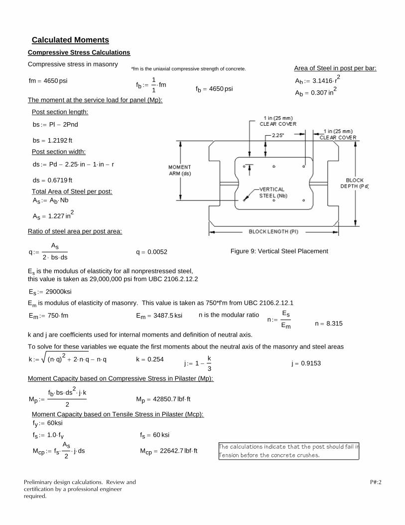
Es is the modulus of elasticity for all nonprestressed steel, this value is taken as 29,000,000 psi from UBC 2106.2.12.2
Es 29000ksi:=
Em is modulus of elasticity of masonry. This value is taken as 750*f'm from UBC 2106.2.12.1
Em 750 fm⋅:= Em 3487.5 ksi= n is the modular ration
Es
Em:= n 8.315=
k and j are coefficients used for internal moments and definition of neutral axis.
To solve for these variables we equate the first moments about the neutral axis of the masonry and steel areas
k n q⋅( )2 2 n⋅ q⋅+ n q⋅−:= k 0.254= j 1k3
−:= j 0.9153=
Moment Capacity based on Compressive Stress in Pilaster (Mp):
Mpfb bs⋅ ds2
⋅ j⋅ k⋅
2:= Mp 42850.7 lbf ft⋅=
Moment Capacity based on Tensile Stress in Pilaster (Mcp):fy 60ksi:=
fs 1.0 fy⋅:= fs 60 ksi=
The calculations indicate that the post should fail inTension before the concrete crushes.Mcp fs
As
2⋅ j⋅ ds⋅:= Mcp 22642.7 lbf ft⋅=
Calculated MomentsCompressive Stress Calculations
Compressive stress in masonry*fm is the uniaxial compressive strength of concrete. Area of Steel in post per bar:
fm 4650 psi= Ab 3.1416 r2⋅:=fb11
fm⋅:= fb 4650 psi= Ab 0.307 in2=
The moment at the service load for panel (Mp):
Post section length:
bs Pl 2Pnd−:=
bs 1.2192 ft=
Post section width:
ds Pd 2.25 in⋅− 1 in⋅− r−:=
ds 0.6719 ft=
Total Area of Steel per post:As Ab Nb⋅:=
As 1.227 in2=
Ratio of steel area per post area:
qAs
2 bs⋅ ds⋅:= q 0.0052= Figure 9: Vertical Steel Placement
Preliminary design calculations. Review and certification by a professional engineer required.
P#:2

Sample Hand Calculations To Determine the Maximum Panel Size based on Tested
Failure Moment


Tributary Area:
s1 33.6161 ft=s1 s w⋅ Pl+ 2 Pnd⋅− 2 0.5 in⋅( )⋅+:=
H 11.159 ft=H z 1−( ) h⋅ 7.16 in⋅+ 4.75 in⋅+:=Post Spacing - Center of Post Block to Center of Post Block (used for design)
Panel Fence height: PanelL 32.3136 ft=
z 17:=Number of block for panel height: PanelL s w⋅:=Panel Length Only: PH 11.833 ft=PH PostH h⋅ 4.75in+:=s 22.0:=
PostH 18:=Number of block in each post:Number of full size block per panel to determine length:
Fence Parameters:PostGrout 48 lbf=Amount of grout per post block:
rbb 0.25 in=r 0.3125 in=
rbbsizebb in⋅( )
2 8⋅:=r
size in⋅( )2 8⋅
:=Radius of bar:Radius of bar:
sizebb 4:=Bond beam bar Size:size 5:=Post bar Size:
Nbb 2:=Quantity number of bond beams:
Nb 4:=Quantity number of rebar in post:
Bond Beam:Post:
Reinforcement Parameters: fm 4650 psi⋅:=Compressive strength of concrete:
Ta 375.1191 ft2=Ta s1 H⋅:=
Concrete Parameters:
Post Block OptionsTable 1(See Table 1)
w 1.4688ft:=Panel Block length:Post 1:=
t 0.469ft:=Panel Block depth:
Large Post = 2h 0.6354ft:=Course height:
Small Post = 1WI 104 ft⋅:=Wall Length:
Post Block Selection:Allan Block Parameters:
**Input variables are in boxed areas**
Fence Number: Section Number:
Date: 02/03/2006 Designed by: RJL
Project Name: Applied Moment Calculations Project Number:
Fence Design Hand Calculations
Pc 1.0ft:=Corner Post Block Length:
(See Table 1) PostGrout = 98 lbf Pnd 0.125 ft=Post Block Notch depth: Pnd =0.1667 ft Pd =1.6667 ft Large Post Block(See Table 1) PostGrout = 48 lbf Pd 0.9688 ft=Post Block depth: Pnd =0.125 ft Pd =0.9688 ft Small Post BlockPl 1.4692ft:=Post Block length:
Preliminary design calculations. Review and certification by a professional engineer required.
P#:1

43.3
Note - The wind speed shall be determined from the wind zone map in Figure 16-1
WIND STAGNATION PRESSURE (qs) FOR FENCES UNDER 12 FEET
Basic wind speed (mph) 70 80 90 100 110 120 130Pressure qs (psf) 9.45 12.3 15.6 19.2 23.25 27.675 43.3
Stagnation pressure: qs 19.2 psf:=
The following tables are reproduced from the 1997 Uniform Building Code, Volume 2
Wind Pressure Conditions:
Basic Wind speed: speed 100 mph:=
Table 16-F WIND STAGNATION PRESSURE (qs) AT STANDARD HEIGHT OF 33 FEET
Basic wind speed (mph) 70 80 90 100 110 120 130Pressure qs (psf) 12.6 16.4 20.8 25.6 31 36.9
Preliminary design calculations. Review and certification by a professional engineer required.
P#:2

Table 16-H PRESSURE COEFFICIENTS (Cq)
Structure of part thereof Description Cq Factor
7. Signs, Flagpoles, lightpoles, minor
structures
1.4
Pressure coefficients: Cq 1.0:=
Table 16-K OCCUPANCY CATEGORY
Occupancy Category Occupancy or functions of structure Wind ImportanceFactor, Iw
Seismic ImportanceFactor, Ip
4. Standard occupancy structuresAll structures housing occupancies
or having functions not listed in Category 1,2, or 3 and Group U
Occupancy towers
1.0 1.0
Wind Importance Factor: Iw 1.0:=
Seismic Importance Factor: Ip 1.0:=
WIND EXPOSURE COEFFIECIENT
Exposure D - represents the most severe exposure in areas with basic wind speeds of 80 mph or greater and has terrain that is flat and unobstructed facing large bodies of water over 1 mile or more in width relative to any quadrant of the building site. Exposure D extends inland from the shoreline 1/4 mile or 10 times the building height, whichever is greaterExposure C - has terrain that is flat and generally open, extending 1/2 mile or more from the site in any full quadrant.Exposure B - has terrain with buildings, forest or surface irregularities, covering at least 20 percent of the ground level area extending 1 mile or more from the site.
Exposure type: Et "NONE":=
Table 16-G COMBINED HEIGHT, EXPOSURE AND GUST FACTOR COEFFICIENT (Ce)
Height above average level of adjoining
ground (ft.)
Exposure D
Exposure C Exposure B
0-15 1.39 1.06 0.6220 1.45 1.13 0.6725 1.5 1.19 0.72
Combined height, exposureand gust factor coefficient: Ce 1.0:=
Preliminary design calculations. Review and certification by a professional engineer required.
P#:3

Calculation for Wind Pressure (P):
P Ce Cq⋅ qs⋅ Iw⋅:= P 19.2psf=
Design Moments:
Mwind_seisP s1⋅ H2
⋅
2:= Mwind_seis 40184.8 lbf ft⋅= < 40500 lbf*ft (Tested Moment at Failure)
Preliminary design calculations. Review and certification by a professional engineer required.
P#:4

Sample Hand Calculations To Determine Moment Above and
Below the Rebar Lap Splice


Mx 29174.4 lb ft=
Mx P x a−( )⋅:=Moment at top of splice:
x 6.75 ft=x L hs−:=Distance from top ofpost to top of splice:
hs 1.906ft:=Top of Splice height above footing:
a 2.698 ft=a L b−:=Post height above Ram position:
42,851 lb*ft Compression22,643 lb*ft Tension
Calculated Moment Capacity from Figure 4:
Mmax 42897.6 lb ft=
Mmax P b⋅:=Maximum Moment:
b 5.958ft:=Ram position above footing:
L 8.656ft:=Total Height of Post:
P 7200 lb⋅:=Ram Force at Failure:
Post 2 Results:
Date: 02/03/2006 Designed by: RJL
Moment Above Splice
Fence Design Hand Calculations