
Fuel Metering
31
Fuel Metering
-
Upload
rabbi35me10 -
Category
Documents
-
view
219 -
download
0
description
IC engine fuel metering
Transcript of Fuel Metering
Fuel Metering

SI Engine Fuel Metering
• The SIE meters fuel into the air stream of amount
dictated by the speed and by the load
– This is usually done by either carburettor or by fuel injector
– It must satisfy the requirements of the engine over its
entire operating regime
– The optimum air-fuel ratio for a SIE is that which gives
required power output with the lowest fuel consumption,
consistent with smooth and reliable operation
– The constraints of emissions control may dictate a different
air-fuel ratio, and may also require the recycling of a
fraction of the exhaust gases (EGR) into the intake system

SI Engine Fuel Metering
• The ratios of air and fuel are required for various
conditions of speed and load, which are:
– Idling and low-load range (throttle almost closed)
– Economy (cruise) or medium-load range (throttle partially
open)
– Power of full-load range (throttle wide open)

SI Engine Fuel Metering
• Fuel system includes - fuel tank, fuel-level indicator, fuel
lines, fuel pump, fuel filter, air cleaner, throttle body, and
intake manifold
• Fuel pumps may be mechanical or electric (in-line or in-
tank)
– They deliver more fuel than required
– Fuel is pressurised - prevents vapour lock
• There are two main types of carburettor:
– Fixed jet (or fixed venturi)
– Variable jet (or variable venturi)
• Fuel injectors are also of two types:
– Single-point (or throttle-body (TBI)) injector
– Multi-point (or port-fuel (PFI)) injector

SI Engine Fuel Metering
• The fuel metering system and manifold have to perform
satisfactorily in both steady-state and transient
conditions
– Fuel will be present in the intake manifold as vapour, liquid
droplets, and liquid film
• There are three basic parts of a carburettor – which are,
air horn, float bowl, and the throttle body
• Internal parts of a carburettor includes
– Float system
– Idle system and low speed system
– Main-metering system
– Accelerator pump system
– Choke system

Carbuettor Float System

Carbuettor Idling and Low-Speed System

Carbuettor Main Metering System

Carbuettor Accelerator Pump System

Carbuettor Choke System

Fixed Jet Carburettor
• Simple fixed jet or fixed venturi carburettor can only
sense air flow rate without distinguishing between fully
open throttle at a slow engine speed or partially closed
throttle at a higher engine speed
• The fuel outlet is at the smallest cross-sectional area so
that the maximum velocity promotes break-up of the
liquid jet and mixing with air; the minimum pressure also
promotes fuel evaporation
– The pressure drop at the maximum air flow rate is about
0.05 bar
– The maximum air flow is when the velocity at the venturi is
supersonic

Fixed Jet Carburettor
• To make allowance for the mixture becoming richer at
larger flow rates a secondary flow of fuel, which reduces
as the air flow rate increases, should be added
– A method of achieving this is the compensating jet and
emulsion tube
• When the choke system is in operation, fuel is drawn
from the float chamber directly, and the manifold acts as
a surface carburettor

Variable Venturi Carburettor
• Variable venturi carburettor is fitted with a piston
• When the throttle is opened, the air flow through the
venturi increases that decreases the pressure
downstream of the venturi and causes the piston to rise
until the pressure on the piston is balanced by its weight
and the force from a light spring
• A tapered needle attached to the piston moves in or out
in the main jet or orifice depending on the piston position
• For starting, extra fuel is provided by a lever that lowers
the jet

Multiple Barrel Carburettor
• Added barrel or barrels improve engine breathing or
volumetric efficiency, especially at high speed
– Two-barrel carburettor
• In one system, each barrel supplies AF mixture for half of the
engine cylinders
• In a staged carburettor, the primary barrel supplies all
cylinders until its throttle valve opens more than 45 degrees -
improves medium to high speed operation
– Four-barrel carburettor – Basically two two-barrel staged
carburettors in a single assembly - one pair of barrels
makes up the primary side, the other two barrels make up
the secondary side
– Multiple carburettors are used in some high-performance
engines; some engines use separate carburettors for each
cylinder

Multiple Barrel Carburettor
• Electronically controlled carburettor
– Operation carburetted electronic engine control system is
very similar to EFI system
– The major difference is that the ECM sends pulses to a
carburettor mixture control solenoid instead of to a fuel
injector
– mixture control solenoid controls mixture richness
– solenoid replaces the vacuum- or mechanically-operated
power system - a plunger extends from the solenoid, the
tipped end acts like the metering rod
– the ECM turns the solenoid on and off very rapidly by
grounding and ungrounding the solenoid coil

EFI System in SI Engines
• Carburettors atomize the fuel by processes relying on
the air speed being greater than the fuel speed at the
fuel nozzle; they also meter the fuel using the air flow as
the independent variable
• Fuel injection differs in both respects
– The fuel speed is greater than the air speed to atomize the
fuel and the fuel is metered proportionally to air flow but
not by air flow itself – a pump is used to generate the
pressure difference necessary to flow the fuel
• Fuel injection system can be classified according to the
following characteristics:
– Single point – one fuel injector serves more than one
cylinder

EFI System in SI Engines
– Multipoint – one fuel injector per cylinder
– Electronic – the metering of the fuel by solenoid action
– Mechanical – the metering of the fuel by cam actuation
– Port – fuel is sprayed into the air stream at the inlet port
– In-cylinder – fuel is sprayed directly into the cylinder
– Low pressure – fuel is injected into gas at a pressure level
on the order of the intake pressure
– High pressure – fuel is injected near the end of
compression into gas at a pressure level on the order of
the compression pressure
– Timed or pulse – each injection has a finite duration,
injection is timed to begin and end at specific times in the
cycle

EFI System in SI Engines
– Continuous or steady – fuel flows through the injector
through all times in the engine cycle; fuel is metered by
controlling the pressure upstream of the fuel injectors
• Some advantages of fuel injection system over
carburetted system are:
– Increased volumetric efficiency and therefore increased
power and torque
– Better thermal efficiency because of improvements
realized in mixture control
– Lowest exhaust emissions because atomization does not
depend on cranking speed, and also fuel supply may be
cut off during deceleration
– More fuel tolerant because distribution can be independent
of vaporization and therefore of the fuel volatility

EFI System in SI Engines
• With improved mixture distribution, the probability that one
cylinder is more prone to knock than the others is reduced so
a lower octane fuel or higher compression ratio can be used
– Charge stratification – with timed fuel injection late in the
intake process or during the compression stroke, it is
possible to stratify the charge
• A rich mixture near the spark plug ensures easy ignition, a
lean end gas reduces the tendency to knock, and a lean
overall charge has favourable emission characteristics
– Elimination of short circuited fuel in turbo or supercharged
four-stroke engines and in all two-stroke engines since the
injection can be timed to begin once the exhaust valve or
port is closed
EFI System in SI Engines
• Normally, electronic Fuel Injection (EFI) system uses
electronic engine control (EEC), sometimes called the
electronic control module (ECM)
• Injectors are fitted with solenoid operated valves
• PFI can deliver fuel more accurately - improves fuel
economy and engine performance
• EFI system contains, among others
– Fuel injector
– Different sensors – throttle position sensor, oxygen sensor,
intake-air temperature sensor, manifold absolute pressure
(MAP) sensor, etc.
– Relay controller
– Fuel pump inertia switch

EFI System in SI Engines

EFI System in SI Engines
Single-point,
continuous
fuel injection
system

EFI System in SI Engines
Mechanical
fuel injection
system

EFI System in SI Engines
• Signals from various electronic sensors come into the
ECM - fuel injection is metered accordingly

EFI System in SI Engines – Injector
CI Engine Injection System
• Diesel fuel injection systems are high pressure for two
reasons:
– The fuel pressure must be greater than the compression
pressure in order to inject the fuel into the cylinder at the
time combustion is to commence
– To impart a high fuel velocity relative to the air so that the
maximum stable size of the droplets will be small enough
that the fuel can evaporate quickly so as not to imepede
the ignition delay
• CI engines use a common rail system (CRS) for fuel
injection
– One pump delivers the fuel to each injector from a fuel
distributing manifold

CI Engine Injection System
When the cam allows the injector
plunger to rise, fuel enters the
orifice (A)
Some of the fuel enters the cavity
ahead of the plunger through the
metering orifice (B) – the greater
the fuel pressure, the greater is
the mass of fuel that enters the
cavity
Most of the fuel (80% or so)
passes through the drain and
return to tank (C)
The bypass flow serves to cool
the injector
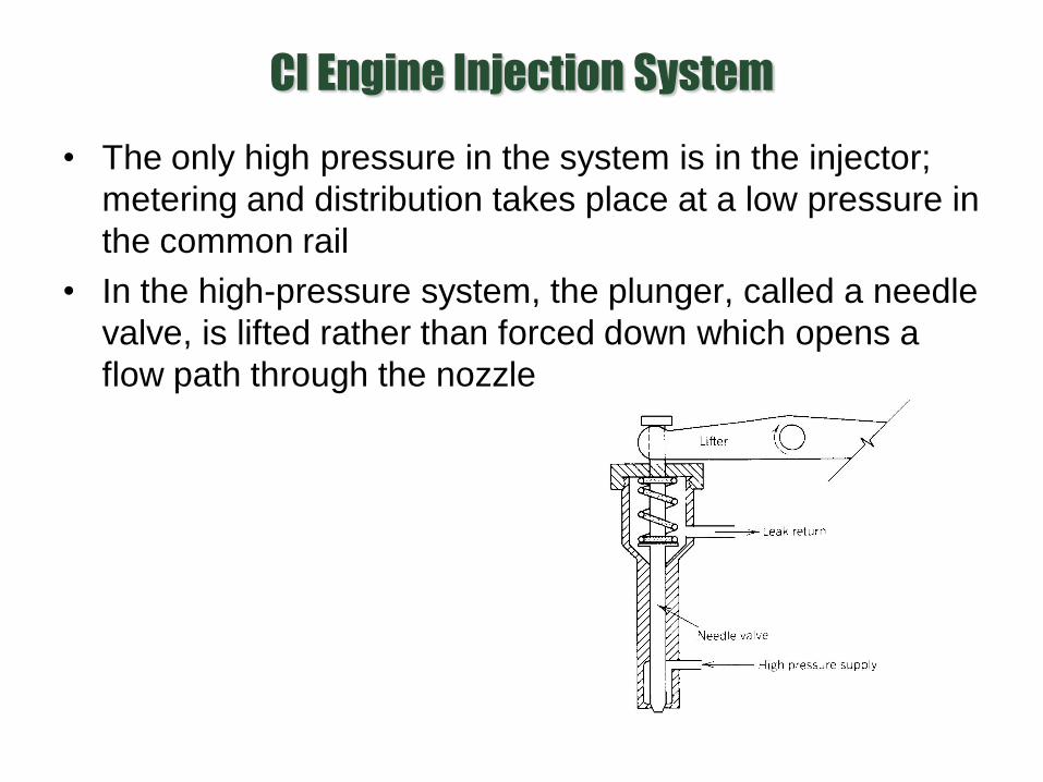
CI Engine Injection System
• The only high pressure in the system is in the injector;
metering and distribution takes place at a low pressure in
the common rail
• In the high-pressure system, the plunger, called a needle
valve, is lifted rather than forced down which opens a
flow path through the nozzle

CI Engine Injection System
• In an electronically controlled fuel
injector, metering is initiated by
actuation of a solenoid operated
three-way valve
– The rail pressure is then applied to
the low pressure piston which is
directly connected to the high
pressure plunger
– The cross-sectional area of the low
pressure piston is 15 times that of the
high pressure piston – thus the high
pressure plunger will have a pressure
of 15 times that of common rail
pressure – therefore, called intensifier

CI Engine Injection System
• Another CI engine injection system employs a positive
displacement pump so that the mass injected is
independent and the fuel pressure adjusts itself
accordingly – known as the jerk-pump system
– The mass of fuel injected is controlled by varying the
displacement of the pumping plunger

CI Engine Injection System